US7038370B2 - Phosphor converted light emitting device - Google Patents
Phosphor converted light emitting deviceDownload PDFInfo
- Publication number
- US7038370B2 US7038370B2US10/785,620US78562004AUS7038370B2US 7038370 B2US7038370 B2US 7038370B2US 78562004 AUS78562004 AUS 78562004AUS 7038370 B2US7038370 B2US 7038370B2
- Authority
- US
- United States
- Prior art keywords
- light
- phosphor
- fluorescent material
- emitting
- radiation source
- Prior art date
- Legal status (The legal status is an assumption and is not a legal conclusion. Google has not performed a legal analysis and makes no representation as to the accuracy of the status listed.)
- Expired - Lifetime
Links
Images


Classifications
- C—CHEMISTRY; METALLURGY
- C09—DYES; PAINTS; POLISHES; NATURAL RESINS; ADHESIVES; COMPOSITIONS NOT OTHERWISE PROVIDED FOR; APPLICATIONS OF MATERIALS NOT OTHERWISE PROVIDED FOR
- C09K—MATERIALS FOR MISCELLANEOUS APPLICATIONS, NOT PROVIDED FOR ELSEWHERE
- C09K11/00—Luminescent, e.g. electroluminescent, chemiluminescent materials
- C09K11/08—Luminescent, e.g. electroluminescent, chemiluminescent materials containing inorganic luminescent materials
- C09K11/77—Luminescent, e.g. electroluminescent, chemiluminescent materials containing inorganic luminescent materials containing rare earth metals
- C09K11/7766—Luminescent, e.g. electroluminescent, chemiluminescent materials containing inorganic luminescent materials containing rare earth metals containing two or more rare earth metals
- C09K11/7774—Aluminates
- H—ELECTRICITY
- H10—SEMICONDUCTOR DEVICES; ELECTRIC SOLID-STATE DEVICES NOT OTHERWISE PROVIDED FOR
- H10H—INORGANIC LIGHT-EMITTING SEMICONDUCTOR DEVICES HAVING POTENTIAL BARRIERS
- H10H20/00—Individual inorganic light-emitting semiconductor devices having potential barriers, e.g. light-emitting diodes [LED]
- H10H20/80—Constructional details
- H10H20/85—Packages
- H10H20/851—Wavelength conversion means
- H10H20/8511—Wavelength conversion means characterised by their material, e.g. binder
- H10H20/8512—Wavelength conversion materials
Definitions
- the present inventiongenerally relates to an illumination system comprising a radiation source and a fluorescent material comprising a phosphor.
- Previous illumination systemshave been based in particular either on the trichromatic (RGB) approach, i.e. on mixing three colors, namely red, green and blue, in which case the latter component may be provided by a phosphor or by the primary emission of the LED or in a second, simplified solution, on the dichromatic (BY) approach, mixing yellow and blue colors, in which case the yellow component may be provided by a yellow phosphor and the blue component may be provided by the primary emission of blue LED.
- RGBtrichromatic
- BYdichromatic
- the dichromatic approach as disclosed in, for example, U.S. Pat. No. 5,998,925uses a blue light emitting diode of InGaN semiconductor combined with a Y 3 Al 5 O 12 :Ce 3+ (YAG-Ce 3+ ) phosphor.
- the YAG-Ce 3+ phosphoris coated on the InGaN LED, and a portion of the blue light emitted from the LED is converted to yellow light by the phosphor. Another portion of the blue light from the LED is transmitted through the phosphor.
- this systememits both blue light emitted from the LED, and yellow light emitted from the phosphor.
- the mixture of blue and yellow emission bandsare perceived as white light by an observer with a CRI in the middle 80s and a color temperature, T e , that ranges from about 6000 K to about 8000 K.
- white light LEDs based on the dichromatic approachcan only be used to a limited extent for general-purpose illumination, on account of their poor color rendering caused by the absence of red color components.
- a systemincludes a radiation source capable of emitting first light and a fluorescent material capable of absorbing the first light and emitting second light having a different wavelength than the first light.
- the fluorescent materialis a phosphor having the formula (Lu 1-x-y-a-b Y x Gd y ) 3 (Al 1-z Ga z ) 5 O 12 :Ce a Pr b wherein 0 ⁇ x ⁇ 1, 0 ⁇ y ⁇ 1, 0 ⁇ z ⁇ 0.1, 0 ⁇ a ⁇ 0.2 and 0 ⁇ b ⁇ 0.1.
- a Pr bis combined with a second fluorescent material capable of emitting third light.
- the second fluorescent materialmay be a red-emitting phosphor, such that the combination of first, second, and third light emitted from the system appears white.
- FIG. 1shows a schematic view of a tri-color white LED lamp comprising a two-phosphor blend positioned in a pathway of light emitted by an LED structure.
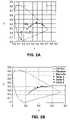
- FIG. 2Ashows the coordinates of phosphor mixtures of (Lu 0.495 Y 0.495 Ce 0.01 ) 3 Al 5 O 12 and CaS in the chromaticity diagram of the Commission Internationals de I'Eclairage (“CIE”).
- FIG. 2Bshows the coordinates of phosphor mixtures of Lu 3 Al 5 O 12 :Ce 3+ and Sr 2 Si 5 N 8 :Eu in the CIE diagram. Blends of these phosphors may be produced to have coordinates close to the black body locus.
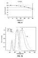
- FIG. 3illustrates emission spectra of green LEDs upon excitation by a blue LED at 460 nm.
- FIGS. 4A and 4Billustrates emission spectra of white LEDs.
- FIG. 5illustrates the excitation and emission spectra of (Lu 0.99 Ce 0.01 ) 3 Al 5 O 12 .
- FIG. 6illustrates the excitation and emission spectra of (Lu 0.989 Ce 0.01 Pr 0.001 ) 3 Al 5 O 12 .
- FIG. 7illustrates the excitation and emission spectra of (Lu 0.495 Y 0.495 Ce 0.01 ) 3 Al 5 O 12 .
- FIG. 8illustrates the relative intensity of Lu 3 Al 5 O 12 :Ce 3+ as a function of temperature.
- FIG. 9illustrates the relative intensity of Sr 2 Si 5 N 8 :Eu 2+ as a function of temperature.
- FIG. 10illustrates excitation and emission spectra of Lu 3 Al 5 O 12 :Ce 3+ and Y 3 Al 5 O 12 :Ce 3+ .
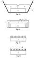
- FIGS. 11 , 12 , 13 , and 14illustrate embodiments of the invention including multiple phosphors.
- Embodiments of the inventionprovide new phosphors that are excitable in the near UV-to-blue range and emit in the visible green range.
- the new phosphorsare capable of absorbing a part of light emitted by a radiation source and emitting light of a wavelength different from the absorbed light.
- Embodiments of the present inventionfocus on a lutetium aluminum garnet as a phosphor in any configuration of an illumination system containing a radiation source, including, but not limited to discharge lamps, fluorescent lamps, LEDs, laser diodes and X-ray tubes.
- the lutetium aluminum garnet phosphoris cerium-activated.
- radiationencompasses radiation in the UV, IR and visible regions of the electromagnetic spectrum.
- the fluorescent material according to embodiments of the inventioncomprises as a phosphor a cerium-activated lutetium-aluminum-garnet compound.
- the phosphorconforms to the general formula (Lu 1-x-y-b Y x Gd y ) 3 (Al 1-z Ga z ) 5 O 12 :Ce a Pr b wherein 0 ⁇ x ⁇ 1, 0 ⁇ y ⁇ 1, 0 ⁇ z ⁇ 0.1, 0 ⁇ a ⁇ 0.2 and 0 ⁇ b ⁇ 0.1.
- This class of phosphor materialis based on activated luminescence of cubic garnet crystals. Gamets are a class of materials with the crystal chemical formula A 3 B 5 O 12 .
- a garnet crystal latticehas three different atomic occupying sites of dodecahedron octacoordination, octahedron hexacoordination and tetrahedron tetracoordination, in which the A cations are eight-coordinated with oxygens and the B cations are either octahedrally (six) or tetrahedrally (four) coordinated with oxygens.
- the crystal structureis cubic with 160 ions per unit cell containing eight formula units.
- the A cationsare lutetium ions alone or in combination with Yttrium and Gadolinium, in combinations and with activator substitutions of cerium and possibly praseodymium.
- the B cationsmay be aluminum and may be gallium or other ions, again, alone, in combinations and/or with substitutions.
- activator ions substituted in the eight-coordinated or six-coordinated sitesthese garnets are luminescent in response to x-ray stimulation.
- a particularly important activator ion, which is x-ray luminescent in this host material,is the Ce 3+ ion located in eight-coordinated sites.
- Lu 3 Al 5 O 12 :Ce phosphorReplacing some of the lutetium in a cerium activated lutetium aluminum garnet, Lu 3 Al 5 O 12 :Ce phosphor with a smaller ion such as gadolinium Gd 3+ or yttrium Y 3+ causes a shift in the phosphor's emission band from green to the yellow range.
- Lu 3 Al 5 O 12 :Ce phosphor with a larger ion such as gallium Ga 3+causes a shift in the phosphor's emission band from green to the blue range.
- Replacing some of the cerium in a cerium-activated lutetium-aluminum-gamet by praseodymium as a co-activatorhas the effect that the praseodymium produces secondary emission that is concentrated in the red region of the visible spectrum, instead of a typical broadband secondary emission from cerium-activated lutetium-aluminum-phosphor that is generally centered in the yellow region of the visible spectrum.
- the amount of praseodymium as a co-activatorcan vary, depending on the amount of red color that may be required in the white output light for a particular application. Compositions having praseodymium as an activator cation present at low concentrations may be particularly desirable since such compositions show a sharp line emission in the red region of the visible spectrum.
- the lutetium concentrationinfluences the color locus of the emission light when used in a light source, in particular an LED.
- the color locus of this phosphorcan be additionally fine-tuned using the ratio of the two concentrations Lu:Ce, which simplifies or optimizes adaptation to any further (yellow or red) phosphors in the LED.
- concentration of Ce in the phosphorincreases, the blue-end of the emission spectrum of the phosphor shifts to longer wavelengths.
- the phosphorcontains about 1 to about 1.5 mole-percent Ce.
- these garnet phosphorsmay be coated with a thin, uniform layer of one or more compounds selected from the group formed by the fluorides and orthophosphates of the elements aluminum, scandium, yttrium, lanthanum gadolinium and lutetium, the oxides of aluminum, yttrium and lanthanum and the nitride of aluminum.
- the phosphors according to the inventionare responsive to ultraviolet light as in fluorescent lamps and light emitting diodes, visible light as in blue-emitting diodes, electrons (as in cathode ray tubes) and x-rays (as in radiography).
- the inventionalso concerns an illumination system comprising a radiation source and a fluorescent material comprising at least one phosphor of general formula (Lu 1-x-y-a-b Y x Gd y ) 3 (Al 1-z Ga z ) 5 O 12 :Ce a Pr b wherein 0 ⁇ x ⁇ 1, 0 ⁇ y ⁇ 1, 0 ⁇ z ⁇ 0.1, 0 ⁇ a ⁇ 0.2 and 0 ⁇ b ⁇ 0.1.
- light emitting componentssuch as those found in discharge lamps and fluorescent lamps, such as mercury low and high pressure discharge lamps, sulfur discharge lamps, and discharge lamps based an molecular radiators are also contemplated for use as radiation sources with the present inventive phosphor compositions.
- the radiation sourceis a light-emitting diode.
- Any configuration of an illumination system which includes a LED and a cerium-activated lutetium-aluminum garnet phosphor compositionis contemplated in the present invention, preferably with addition of other well-known phosphors, which can be combined to achieve a specific color or white light of high efficiency and/or high color rendering index (“CRI”) at a required color temperature, when irradiated by a LED emitting primary UV or blue light as specified above.
- White-emitting devices according to embodiments of the present inventionare based on the combination of blue, red, and green colors. In some embodiments, the yellow to green and the red phosphors are so broad-banded that they have a sufficient proportion of emission throughout the whole spectral region.
- the second phosphormay be, for example, a red-emitting phosphor, such as a red emitting europium-activated phosphor selected from the group of (Ca 1-x Sr x )S:Eu wherein 0 ⁇ x ⁇ 1 and (Sr 1-x-y Ba x Ca y ) 2-z Si 5-a Al a N 8-a O a :Eu z wherein 0 ⁇ a ⁇ 5, 0 ⁇ x ⁇ 1, 0 ⁇ y ⁇ 1, and 0 ⁇ z ⁇ 1.
- a red-emitting phosphorsuch as a red emitting europium-activated phosphor selected from the group of (Ca 1-x Sr x )S:Eu wherein 0 ⁇ x ⁇ 1 and (Sr 1-x-y Ba x Ca y ) 2-z Si 5-a Al a N 8-a O a :Eu z wherein 0 ⁇ a ⁇ 5, 0 ⁇ x ⁇ 1, 0 ⁇ y ⁇ 1, and 0 ⁇ z ⁇ 1.
- a europium activated calcium strontium sulfideis used, which is a high chromaticity red phosphor excitable from the near UV (400 nm) to the blue-green (500 nm) with high quantum efficiency.
- this phosphorfor luminescent conversion of primary LED light it is necessary to modify the photophysical characteristics to achieve, for example, efficacy, color specifications and life time of related light emitting devices.
- the chromaticity and quantum efficiency of the europium activated strontium sulfidecan be modified through the substitution of divalent metal ions for strontium from the list including Ba, Ca, Mg, and Zn. Suitable red phosphors are described in the following table:
- the phosphor blendcomprises a mixture of predetermined amounts and relative proportions of garnet-structured lutetium-aluminum oxide activated by cerium and calcium-strontium sulfide activated by divalent europium.
- the relative phosphor proportionsare such that the composite emission of the first phosphor layer falls approximately within the warm-white ellipse as inscribed on the x-y chromaticity diagram of the ICI system.
- the spectra of such white emitting devicescomprising three different blends of Lu 3 Al 5 O 12 :Ce and CaS:Eu are given in FIG. 4A .
- FIG. 4Billustrates spectra of three white devices including blends of Lu 3 Al 5 O 12 :Ce and Sr 2 Si 5 N 8 :Eu, excited by a blue LED at 450 nm.
- FIG. 1A detailed construction of such a light-emitting device according to embodiments of the invention is shown in FIG. 1 .
- the device of FIG. 1comprises an LED 1 positioned in a reflector cup 2 .
- a phosphor composition 4 , 5is positioned in the path of light emitted by LED 1 .
- the phosphor compositionis embedded in a resin.
- the shape of reflector cup 2may be selected to provide a particular pattern of light emitted from the device, as is known in the art.
- the walls of reflector cup 2can be parabolic.
- the devicefurther comprises a polymer for encapsulating the phosphor or phosphor blend.
- the phosphor or phosphor blendshould exhibit high stability properties in the encapsulant.
- the polymeris optically clear to prevent significant light scattering.
- the polymeris selected from the group consisting of epoxy and silicone resins.
- a variety of polymersare known in the LED industry for making LED lamps. Adding the phosphor mixture to a liquid that is a polymer precursor can perform encapsulation.
- the phosphor mixturecan be a powder. Introducing phosphor particles into polymer precursor liquid results in formation of a slurry (i.e. a suspension of particles). Upon polymerization, the phosphor mixture is fixed rigidly in place by the encapsulation.
- both the composition and the LEDare encapsulated in the polymer.
- the phosphorsare applied either separately or in a mixture.
- the phosphorscompletely or partially absorb the light from the LED and emit it again in other spectral regions (primarily yellow and green) in a sufficiently broad band (specifically with a significant proportion of red) that an overall emission with the desired color point is formed.
- the wavelength of the LEDis tuned to the particular phosphors in the blend such that each of the phosphors in the blend is excited by emission from the LED.
- a phosphor blend using wide band phosphors according to embodiments of the inventionmay have a relatively high color rendering index, as high as 91–93.
- the phosphor blendmay also include a phosphor that emits blue light.
- a CRI of 100is an indication that the light emitted from the light source is similar to that from a black body source, i.e. an incandescent or halogen lamp.
- a CRI of 85 to 95can be attained by applying a phosphor mixture comprising Lu 3 Al 5 O 12 :Ce and CaS:Eu to a blue-emitting LED.
- FIGS. 2A and 2Bshow the color coordinates of a range of illumination systems providing white light that can be produced from various combinations of blue LEDs and a cerium-activated lutetium-aluminum-garnet phosphor and CaS:Eu or Sr 2 Si 5 N 8 :Eu of the present invention.
- More than one phosphor according to embodiments of the present inventionmay be incorporated in the same device to provide for color adjustment.
- the green-emitting phosphormay be combined when appropriate, with a further yellow or red-emitting phosphor for the production of specific colored light and more preferably for production of white light with a high color-rendering index of greater than 80.
- a green emissioncan be generated which is shown in some examples in FIG. 3 .
- the amount of phosphor disposed on the deviceincreases, eventually all of the emission from the LED is absorbed, such that only emission from the phosphor remains. Devices with such heavy phosphor loading may be used in applications requiring green light.
- the garnet phosphors described aboveemit a broad band in the yellow-green spectral range of the visible spectrum with very high intensity under both UV and blue excitations and thus can provide the green component in LEDs emitting specific colors or white light. Total conversion efficiency can be up to 90%. Additional important characteristics of the phosphors include 1) resistance to thermal quenching of luminescence at typical device operating temperatures (e.g. 80° C.); 2) lack of interfering reactivity with the encapsulating resins used in the device fabrication; 3) suitable absorptive profiles to minimize dead absorption within the visible spectrum; 4) a temporally stable luminous output over the operating lifetime of the device and; 5) compositionally controlled tuning of the phosphors excitation and emission properties.
- Sr 2 Si 5 N 8 :Eu 2+is preferred as a red phosphor as it exhibits similar performance at high temperatures, as illustrated in FIG. 9 , which illustrates the relative intensity of Sr 2 Si 5 N 8 :Eu 2+ as a function of temperature.
- the Sr 2 Si 5 N 8 :Eu 2+ emission intensityis 90% room temperature intensity.
- Lutetium-containing garnet phosphors included with other phosphors in devices designed to emit white lightmay offer improved color rendering over garnet phosphors that do not include lutetium, such as Y 3 Al 5 O 12 :Ce 3+ .
- the improved color renderingis due to the smaller Stokes' shift of Lu 3 Al 5 O 12 :Ce 3+ relative to Y 3 Al 5 O 12 :Ce 3+ .
- Phosphorssuch as Lu 3 Al 5 O 12 :Ce 3+ and Y 3 Al 5 O 12 :Ce 3+ absorb an excitation energy typically in the form of radiation, store the energy, then emit the stored energy as radiation of a different energy.
- 11–14illustrate embodiments of the device where the red-emitting phosphor and lutetium-containing garnet phosphor are deposited such that absorption by the red-emitting phosphor of light emitted by the lutetium-containing garnet phosphor is minimized.
- the lutetium-containing garnet phosphor 5is mixed with a resin or other transparent material and disposed on one side of reflector cup 2 , while any other phosphors 4 are mixed separately with a resin or other transparent material and disposed on the other side of reflector cup 2 , such that slurry 5 does not appreciably mix with slurry 4 .
- the viscosity of the transparent material forming the slurryis selected to avoid mixing phosphor 4 with phosphor 5 .
- lutetium-containing garnet phosphor 5 and any other phosphors 4are adjacent to each other, rather than mixed in the same slurry, light emitted by lutetium-containing garnet phosphor 5 is less likely to be absorbed by any red-emitting phosphors in slurry 4 .
- the lutetium-containing garnet phosphor 5 and other phosphors 4are deposited over LED 1 as discrete layers.
- Phosphor layer 4including any red-emitting phosphors, is deposited closest to LED 1 .
- Lutetium-containing garnet phosphor 5is then deposited over phosphor layer 4 .
- Phosphor layers 4 and 5may be separated by an optional transparent layer 6 .
- Phosphor layers 4 and 5may be deposited as slurries in a resin or other transparent material; deposited as thin films by, for example, electron beam evaporation, thermal evaporation, rf-sputtering, chemical vapor deposition, or atomic layer epitaxy; or deposited as conformal layers over LED 1 by, for example, screen printing, stenciling as described in U.S. Pat. No. 6,650,044, or by electrophoretic deposition as described in U.S. Pat. No. 6,576,488. Thin films are described in more detail in U.S. Pat. No. 6,696,703. Each of U.S. Pat. No. 6,696,703, U.S. Pat. No. 6,650,044 and U.S. Pat. No.
- 6,576,488are incorporated herein by reference.
- the phosphor in a conformal layerIn contrast to a thin film, which typically behaves as a single, large phosphor particle, the phosphor in a conformal layer generally behaves as multiple phosphor particles.
- a thin filmtypically contains no materials other than phosphor.
- a conformal layeroften includes materials other than phosphor, such as, for example, silica.
- the lutetium-containing garnet phosphor 5 and other phosphors 4are deposited on LED 1 in a plurality of small regions.
- the different regionsmay form a pattern, such as a checkerboard pattern. If light from LED 1 is to escape unconverted, as in the case where blue light emitted by the LED mixes with green and red light emitted by phosphors to make white light, the amount of unconverted light may be controlled by controlling the thickness of phosphor regions 4 and 5 , or by leaving regions of LED 1 uncovered, or covered by an optional transparent material 7 that does not convert the light emitted by LED 1 . Patterns of different phosphor layers as illustrated in FIG.
- a first layer of phosphor by electrophoretic depositionmay be formed by depositing a first layer of phosphor by electrophoretic deposition, patterning that layer using conventional lithography and etching techniques, then depositing a second phosphor layer by electrophoretic deposition.
- patterns of phosphor layersmay be deposited by screen printing or ink jet printing.
- a pattern of phosphor layersmay be formed by pipetting the individual phosphor mixes 4 and 5 into wells in a clear plastic microplate used for microbiology. The phosphor-filled microplate is then placed on LED 1 . Phosphor-filled microplates may be formed separately from LED 1 .
- a plurality of small regions of phosphor 4which includes any red-emitting phosphors, is formed on the surface of LED 1 .
- a layer of lutetium-containing garnet phosphor 5is then deposited over the plurality of regions of phosphor 4 .
- FIGS. 11–14avoid the problem of light being absorbed and reemitted by the lutetium-containing garnet phosphor prior to being incident on a red-emitting phosphor.
- light emitted by LED 1is incident on the red-emitting phosphor first, or is incident on the red-emitting phosphor and the lutetium-containing garnet phosphor in separate regions.
- the arrangements illustrated in FIGS. 11–14thus reduce the probability of light emitted from the lutetium-containing garnet phosphor being absorbed by a red-emitting phosphor.
- Lutetium-containing garnet phosphors according to the present inventionare easily synthesized, as illustrated in the following example:
- one or more of the starting materialsmay be oxygen-containing compounds such as oxides, nitrates, sulfates, acetates, citrates. or chlorates, which are soluble in a nitric acid solution.
- nitric acid solutionamounts of Lu 2 O 3 , Al(NO 3 ) 3 .9H 2 O, Ce(NO 3 ) 3 .6H 2 O and AlF 3 are blended and dissolved in a nitric acid solution.
- the strength of the acid solutionis chosen to rapidly dissolve the oxygen-containing compounds and the choice is within the skill of a person skilled in the art.
- the nitric acid solutionis evaporated.
- the dried precipitateis ball milled or otherwise thoroughly blended and then calcined in a CO-atmosphere at about 1300° C. for a sufficient time to ensure a substantially complete dehydration of the starting material.
- the calcinationmay be carried out at a constant temperature.
- the calcinations temperaturemay be ramped from ambient to and held at the final temperature for the duration of the calcination.
- the calcined materialis similarly fired at 1500–1700° C. under a reducing atmosphere such as H 2 , CO, or a mixture of one of these gases with an inert gas.
- the calcined materialis fired for a sufficient time for the decomposition of the oxygen-containing compounds to convert all of the calcined material to the desired phosphor composition.
- the resulting powderis milled on a roller bench for several hours.
- the milled powderhas an average particle size of 40 to 60 ⁇ m. Its quantum efficiency is 90% and its lumen equivalent is between 430 and 470 lm/W.
- the table belowgives the wavelength and color point of several suitable phosphor compounds.
- the excitation band of (Lu 0.989 Ce 0.010 Pr 0.001 ) 3 Al 5 O 12is a broad band (515–540 nm) with a peak extending from 515–540 nm and a side band at 610 nm.
- a phosphor blendcomprising at least one of the suitable red phosphors described above is suspended into a silicone precursor. A droplet of this suspension is deposited onto the LED chip and subsequently polymerized. A plastic lens seals the LED.
Landscapes
- Chemical & Material Sciences (AREA)
- Inorganic Chemistry (AREA)
- Engineering & Computer Science (AREA)
- Materials Engineering (AREA)
- Organic Chemistry (AREA)
- Luminescent Compositions (AREA)
Abstract
Description
| Phosphor composition | λmax[nm] | Color point x, y |
| SrS:Eu | 610 | 0.627, 0.372 |
| (Sr1−x−yBaxCay)2Si5N8:Eu | 615 | 0.615, 0.384 |
| (Sr1−x−yBaxCay)2Si5−xAlxN8−x:Eu | 615–650 | Depends on x, y |
| CaS:Eu | 655 | 0.700, 0.303 |
| (Sr1−xCax)S:Eu | 610–655 | Depends on x, y |
| Phosphor composition | λmax[nm] | Color point x, y |
| (Lu0.99Ce0.01)3Al5O12 | 515 + 540 | 0.339, 0.579 |
| (Lu0.989Ce0.010Pr.001)3Al5O12 | 515 + 540 + 610 | 0.332, 0.574 |
| (Lu0.495Y0.495Ce0.01)3Al5O12 | 525 + 550 | 0.377, 0.570 |
| (Lu0.75Gd0.24Ce0.01)3Al5O12 | 520 + 545 | 0.350, 0.573 |
Claims (22)
Priority Applications (4)
| Application Number | Priority Date | Filing Date | Title |
|---|---|---|---|
| EP05101220.1AEP1566426B1 (en) | 2004-02-23 | 2005-02-18 | Phosphor converted light emitting device |
| TW094105105ATWI381044B (en) | 2004-02-23 | 2005-02-21 | Phosphor conversion illuminating device |
| JP2005084754AJP4787521B2 (en) | 2004-02-23 | 2005-02-23 | Phosphor conversion light emitting device |
| JP2011050587AJP5186016B2 (en) | 2004-02-23 | 2011-03-08 | Phosphor conversion light emitting device |
Applications Claiming Priority (2)
| Application Number | Priority Date | Filing Date | Title |
|---|---|---|---|
| EP031100668.7 | 2003-03-17 | ||
| EP03100668 | 2003-03-17 |
Publications (2)
| Publication Number | Publication Date |
|---|---|
| US20040256974A1 US20040256974A1 (en) | 2004-12-23 |
| US7038370B2true US7038370B2 (en) | 2006-05-02 |
Family
ID=33016951
Family Applications (2)
| Application Number | Title | Priority Date | Filing Date |
|---|---|---|---|
| US10/785,620Expired - LifetimeUS7038370B2 (en) | 2003-03-17 | 2004-02-23 | Phosphor converted light emitting device |
| US10/549,231Expired - LifetimeUS7573189B2 (en) | 2003-03-17 | 2004-03-05 | Illumination system comprising a radiation source and a fluorescent material |
Family Applications After (1)
| Application Number | Title | Priority Date | Filing Date |
|---|---|---|---|
| US10/549,231Expired - LifetimeUS7573189B2 (en) | 2003-03-17 | 2004-03-05 | Illumination system comprising a radiation source and a fluorescent material |
Country Status (6)
| Country | Link |
|---|---|
| US (2) | US7038370B2 (en) |
| EP (1) | EP1604141B1 (en) |
| JP (1) | JP2006520836A (en) |
| CN (1) | CN100529509C (en) |
| TW (1) | TWI347968B (en) |
| WO (1) | WO2004084261A2 (en) |
Cited By (25)
| Publication number | Priority date | Publication date | Assignee | Title |
|---|---|---|---|---|
| US20070252513A1 (en)* | 2004-07-05 | 2007-11-01 | Koninklijke Philips Electronics, N.V. | Illumination System Comprising a Radiation Source and a Fluorescent Material |
| US20080001126A1 (en)* | 2004-09-22 | 2008-01-03 | National Institute For Materials Science | Phosphor, Production Method Thereof and Light Emitting Instrument |
| US20080122343A1 (en)* | 2006-11-28 | 2008-05-29 | Dowa Electronics Materials Co., Ltd. | Light-emitting device and manufacturing method thereof |
| EP1973325A1 (en) | 2007-03-20 | 2008-09-24 | Xerox Corporation | Document Illuminator with LED-Driven Phosphor |
| US20090021926A1 (en)* | 2007-07-18 | 2009-01-22 | Epistar Corporation | Wavelength converting system |
| US20100084962A1 (en)* | 2007-03-06 | 2010-04-08 | Merck Patent Gesellschaft | Luminophores made of doped garnet for pcleds |
| US20100123104A1 (en)* | 2008-11-17 | 2010-05-20 | Collins Brian T | Phosphor composition |
| US7772604B2 (en) | 2006-01-05 | 2010-08-10 | Illumitex | Separate optical device for directing light from an LED |
| US7789531B2 (en) | 2006-10-02 | 2010-09-07 | Illumitex, Inc. | LED system and method |
| US7829358B2 (en) | 2008-02-08 | 2010-11-09 | Illumitex, Inc. | System and method for emitter layer shaping |
| US20110063830A1 (en)* | 2004-05-05 | 2011-03-17 | Rensselaer Polytechnic Institute | Lighting source using solid state emitter and phosphor materials |
| WO2011033406A2 (en) | 2009-09-17 | 2011-03-24 | Koninklijke Philips Electronics N.V. | Molded lens incorporating a window element |
| US8115217B2 (en) | 2008-12-11 | 2012-02-14 | Illumitex, Inc. | Systems and methods for packaging light-emitting diode devices |
| US20130063926A1 (en)* | 2010-05-22 | 2013-03-14 | Merck Patent Gesellschaft Mit Beschrankter Haftung | Phosphors |
| US8449128B2 (en) | 2009-08-20 | 2013-05-28 | Illumitex, Inc. | System and method for a lens and phosphor layer |
| US8585253B2 (en) | 2009-08-20 | 2013-11-19 | Illumitex, Inc. | System and method for color mixing lens array |
| US8937332B2 (en) | 2011-02-04 | 2015-01-20 | Osram Sylvania Inc. | Wavelength converter for an LED and LED containing same |
| US20150128488A1 (en)* | 2012-07-11 | 2015-05-14 | Koninklijke Philips N.V. | Lighting device capable of providing horticulture light and method of illuminating horticulture |
| US20160043289A1 (en)* | 2013-10-23 | 2016-02-11 | National Institute For Materials Science | Single crystal phosphor, phosphor-containing member and light-emitting device |
| US9399733B2 (en) | 2010-10-22 | 2016-07-26 | Anatoly Vasilyevich Vishnyakov | Luminescent material for solid-state sources of white light |
| CN106635016A (en)* | 2016-12-28 | 2017-05-10 | 诚善材料科技(盐城)有限公司 | Phosphor, preparation method thereof and light-emitting device |
| WO2018085670A1 (en) | 2016-11-03 | 2018-05-11 | Lumileds Llc | Inorganic bonded devices and structures |
| US11329206B2 (en) | 2020-09-28 | 2022-05-10 | Dominant Opto Technologies Sdn Bhd | Lead frame and housing sub-assembly for use in a light emitting diode package and method for manufacturing the same |
| US11444225B2 (en) | 2020-09-08 | 2022-09-13 | Dominant Opto Technologies Sdn Bhd | Light emitting diode package having a protective coating |
| US11910702B2 (en)* | 2017-11-07 | 2024-02-20 | Universal Display Corporation | Organic electroluminescent devices |
Families Citing this family (102)
| Publication number | Priority date | Publication date | Assignee | Title |
|---|---|---|---|---|
| US7915085B2 (en) | 2003-09-18 | 2011-03-29 | Cree, Inc. | Molded chip fabrication method |
| EP1566426B1 (en) | 2004-02-23 | 2015-12-02 | Philips Lumileds Lighting Company LLC | Phosphor converted light emitting device |
| US20070194693A1 (en)* | 2004-03-26 | 2007-08-23 | Hajime Saito | Light-Emitting Device |
| US7462086B2 (en) | 2004-04-21 | 2008-12-09 | Philips Lumileds Lighting Company, Llc | Phosphor for phosphor-converted semiconductor light emitting device |
| US7372198B2 (en)* | 2004-09-23 | 2008-05-13 | Cree, Inc. | Semiconductor light emitting devices including patternable films comprising transparent silicone and phosphor |
| WO2006061778A1 (en)* | 2004-12-06 | 2006-06-15 | Philips Intellectual Property & Standards Gmbh | Illumination system comprising a radiation source and a blue-emitting phospor |
| WO2006061729A2 (en)* | 2004-12-06 | 2006-06-15 | Philips Intellectual Property & Standards Gmbh | Organic electroluminescent light source |
| US7671529B2 (en)* | 2004-12-10 | 2010-03-02 | Philips Lumileds Lighting Company, Llc | Phosphor converted light emitting device |
| JP5233119B2 (en) | 2004-12-21 | 2013-07-10 | 日立金属株式会社 | Fluorescent material and manufacturing method thereof, radiation detector using fluorescent material, and X-ray CT apparatus |
| CN100477302C (en)* | 2005-02-23 | 2009-04-08 | 李洲科技股份有限公司 | Multi-wavelength light emitting diode and light emitting chip structure thereof |
| CN101128563B (en)* | 2005-02-28 | 2012-05-23 | 三菱化学株式会社 | Phosphor, its production method and its application |
| US7439668B2 (en)* | 2005-03-01 | 2008-10-21 | Lumination Llc | Oxynitride phosphors for use in lighting applications having improved color quality |
| CN100566490C (en)* | 2005-03-14 | 2009-12-02 | 皇家飞利浦电子股份有限公司 | Phosphor in the polycrystalline ceramic structure and the light-emitting component that comprises this phosphor |
| JP2006278980A (en)* | 2005-03-30 | 2006-10-12 | Sanyo Electric Co Ltd | Semiconductor light emitting device |
| WO2006111907A2 (en)* | 2005-04-20 | 2006-10-26 | Philips Intellectual Property & Standards Gmbh | Illumination system comprising a ceramic luminescence converter |
| WO2006129228A2 (en)* | 2005-06-02 | 2006-12-07 | Philips Intellectual Property & Standards Gmbh | Illumination system comprising color deficiency compensating luminescent material |
| DE102005038698A1 (en)* | 2005-07-08 | 2007-01-18 | Tridonic Optoelectronics Gmbh | Optoelectronic components with adhesion promoter |
| JP2007036042A (en)* | 2005-07-28 | 2007-02-08 | Sony Corp | Light-emitting apparatus and optical apparatus |
| US8563339B2 (en) | 2005-08-25 | 2013-10-22 | Cree, Inc. | System for and method for closed loop electrophoretic deposition of phosphor materials on semiconductor devices |
| US7847302B2 (en)* | 2005-08-26 | 2010-12-07 | Koninklijke Philips Electronics, N.V. | Blue LED with phosphor layer for producing white light and different phosphor in outer lens for reducing color temperature |
| JP2007204730A (en)* | 2005-09-06 | 2007-08-16 | Sharp Corp | Phosphor and light-emitting device |
| WO2007080555A1 (en) | 2006-01-16 | 2007-07-19 | Koninklijke Philips Electronics N.V. | Phosphor converted light emitting device |
| JP4749870B2 (en)* | 2006-01-24 | 2011-08-17 | 新光電気工業株式会社 | Method for manufacturing light emitting device |
| US8469760B2 (en)* | 2006-03-31 | 2013-06-25 | Dowa Electronics Materials Co., Ltd. | Light emitting device and method for producing same |
| RU2422945C2 (en)* | 2006-04-25 | 2011-06-27 | Конинклейке Филипс Электроникс Н.В. | Fluorescent illumination, generating white light |
| JP4837045B2 (en)* | 2006-10-12 | 2011-12-14 | パナソニック株式会社 | Light emitting device and manufacturing method thereof |
| KR101370372B1 (en)* | 2006-10-18 | 2014-03-05 | 코닌클리케 필립스 엔.브이. | Illumination system and display device |
| US9120975B2 (en) | 2006-10-20 | 2015-09-01 | Intematix Corporation | Yellow-green to yellow-emitting phosphors based on terbium-containing aluminates |
| US8475683B2 (en) | 2006-10-20 | 2013-07-02 | Intematix Corporation | Yellow-green to yellow-emitting phosphors based on halogenated-aluminates |
| US8529791B2 (en)* | 2006-10-20 | 2013-09-10 | Intematix Corporation | Green-emitting, garnet-based phosphors in general and backlighting applications |
| US8133461B2 (en) | 2006-10-20 | 2012-03-13 | Intematix Corporation | Nano-YAG:Ce phosphor compositions and their methods of preparation |
| EP2102684A2 (en)* | 2007-01-05 | 2009-09-23 | Koninklijke Philips Electronics N.V. | Fast radiation detectors |
| CN101250408B (en)* | 2007-01-22 | 2011-03-23 | 罗维鸿 | Warm-white light-emitting diode and fluorescent powder having orange radiation thereof |
| US9024349B2 (en) | 2007-01-22 | 2015-05-05 | Cree, Inc. | Wafer level phosphor coating method and devices fabricated utilizing method |
| US9159888B2 (en) | 2007-01-22 | 2015-10-13 | Cree, Inc. | Wafer level phosphor coating method and devices fabricated utilizing method |
| US7927409B2 (en)* | 2007-03-23 | 2011-04-19 | Hewlett-Packard Development Company, L.P. | Multi-colored images viewable under non-visible radiation |
| JP2008285606A (en)* | 2007-05-18 | 2008-11-27 | Nec Lighting Ltd | Phosphor, method for producing the same and light-emitting device |
| US7700967B2 (en)* | 2007-05-25 | 2010-04-20 | Philips Lumileds Lighting Company Llc | Illumination device with a wavelength converting element held by a support structure having an aperture |
| JP2008308510A (en)* | 2007-06-12 | 2008-12-25 | Sony Corp | Light emission composition, optical apparatus using this, and display apparatus using this |
| US7905618B2 (en) | 2007-07-19 | 2011-03-15 | Samsung Led Co., Ltd. | Backlight unit |
| KR100966374B1 (en)* | 2007-08-27 | 2010-07-01 | 삼성엘이디 주식회사 | Surface light source using white LED and LCD backlight unit having same |
| US9041285B2 (en) | 2007-12-14 | 2015-05-26 | Cree, Inc. | Phosphor distribution in LED lamps using centrifugal force |
| TW200929578A (en)* | 2007-12-31 | 2009-07-01 | Ind Tech Res Inst | Transparent sola cell module |
| US8878219B2 (en)* | 2008-01-11 | 2014-11-04 | Cree, Inc. | Flip-chip phosphor coating method and devices fabricated utilizing method |
| US8058088B2 (en) | 2008-01-15 | 2011-11-15 | Cree, Inc. | Phosphor coating systems and methods for light emitting structures and packaged light emitting diodes including phosphor coating |
| JP5168017B2 (en)* | 2008-08-04 | 2013-03-21 | 日亜化学工業株式会社 | Phosphor and fluorescent lamp using the same |
| JP5680278B2 (en)* | 2009-02-13 | 2015-03-04 | シャープ株式会社 | Light emitting device |
| RU2011142752A (en)* | 2009-03-23 | 2013-04-27 | Конинклейке Филипс Электроникс Н.В. | LIGHTING EQUIPMENT WITH LUMINESCENT ENVIRONMENT, RELEVANT LIGHTING SYSTEM, CONTAINING LIGHT-Emitting DEVICE, AND RELATED LUMINESCENT ENVIRONMENT |
| DE102009037732A1 (en)* | 2009-08-17 | 2011-02-24 | Osram Gesellschaft mit beschränkter Haftung | Conversion LED with high efficiency |
| US8646949B2 (en)* | 2010-03-03 | 2014-02-11 | LumenFlow Corp. | Constrained folded path resonant white light scintillator |
| US8643038B2 (en)* | 2010-03-09 | 2014-02-04 | Cree, Inc. | Warm white LEDs having high color rendering index values and related luminophoric mediums |
| US20110220920A1 (en)* | 2010-03-09 | 2011-09-15 | Brian Thomas Collins | Methods of forming warm white light emitting devices having high color rendering index values and related light emitting devices |
| WO2011115820A1 (en)* | 2010-03-19 | 2011-09-22 | Nitto Denko Corporation | Garnet-based phosphor ceramic sheets for light emitting device |
| US8273589B2 (en)* | 2010-03-19 | 2012-09-25 | Micron Technology, Inc. | Light emitting diodes and methods for manufacturing light emitting diodes |
| TW201144410A (en)* | 2010-06-03 | 2011-12-16 | qi-rui Cai | Warm white light emitting diode and lutetium-based phosphor powder thereof |
| EP2593527B1 (en)* | 2010-07-13 | 2014-04-02 | Koninklijke Philips N.V. | Uv-a or uv-b-emitting discharge lamp |
| US10546846B2 (en) | 2010-07-23 | 2020-01-28 | Cree, Inc. | Light transmission control for masking appearance of solid state light sources |
| TWI457418B (en)* | 2010-09-29 | 2014-10-21 | Au Optronics Corp | White light emitting diode device, light emitting device and liquid crystal display |
| WO2012046642A1 (en)* | 2010-10-05 | 2012-04-12 | 株式会社ネモト・ルミマテリアル | Green light-emitting phosphor and light-emitting device |
| TWI476961B (en)* | 2010-10-12 | 2015-03-11 | 友達光電股份有限公司 | Led apparatus |
| JP6369774B2 (en)* | 2010-10-29 | 2018-08-08 | 株式会社光波 | Light emitting device |
| CN103347982B (en) | 2010-12-01 | 2016-05-25 | 日东电工株式会社 | There is emissivity ceramic material and manufacture method and the using method of doping content gradient |
| US10522518B2 (en) | 2010-12-23 | 2019-12-31 | Bench Walk Lighting, LLC | Light source with tunable CRI |
| US9166126B2 (en) | 2011-01-31 | 2015-10-20 | Cree, Inc. | Conformally coated light emitting devices and methods for providing the same |
| FI122809B (en)* | 2011-02-15 | 2012-07-13 | Marimils Oy | Light source and light source band |
| WO2012116114A1 (en) | 2011-02-24 | 2012-08-30 | Nitto Denko Corporation | Light emitting composite with phosphor components |
| CN103443244B (en)* | 2011-03-08 | 2016-11-09 | 英特曼帝克司公司 | Yellow-green to yellow-emitting phosphors based on haloaluminate |
| JP5580777B2 (en) | 2011-04-25 | 2014-08-27 | 浜松ホトニクス株式会社 | Ultraviolet light generation target, electron beam excited ultraviolet light source, and method for producing ultraviolet light generation target |
| EP2703471B1 (en) | 2011-04-25 | 2020-02-19 | Hamamatsu Photonics K.K. | Ultraviolet light generating target, electron-beam-excited ultraviolet light source, and method for producing ultraviolet light generating target |
| US8814621B2 (en) | 2011-06-03 | 2014-08-26 | Cree, Inc. | Methods of determining and making red nitride compositions |
| US8729790B2 (en) | 2011-06-03 | 2014-05-20 | Cree, Inc. | Coated phosphors and light emitting devices including the same |
| US8906263B2 (en) | 2011-06-03 | 2014-12-09 | Cree, Inc. | Red nitride phosphors |
| US8747697B2 (en) | 2011-06-07 | 2014-06-10 | Cree, Inc. | Gallium-substituted yttrium aluminum garnet phosphor and light emitting devices including the same |
| DE102011078402A1 (en) | 2011-06-30 | 2013-01-03 | Osram Ag | Conversion element and light-emitting diode with such a conversion element |
| CN103703102B (en) | 2011-07-05 | 2015-09-30 | 松下电器产业株式会社 | Rare earth class aluminium garnet type fluor and employ the light-emitting device of this fluor |
| KR20130010283A (en)* | 2011-07-18 | 2013-01-28 | 삼성전자주식회사 | White light emitting device, display apparatus and illumination apparatus |
| DE102011115879A1 (en)* | 2011-10-12 | 2013-04-18 | Osram Opto Semiconductors Gmbh | Optoelectronic component and phosphors |
| WO2013074158A1 (en)* | 2011-11-16 | 2013-05-23 | Intematix Corporation | Green and yellow aluminate phosphors |
| JP5972571B2 (en)* | 2011-12-28 | 2016-08-17 | 日東電工株式会社 | Optical semiconductor device and lighting device |
| US9525110B2 (en) | 2012-10-16 | 2016-12-20 | Denka Company Limited | Phosphor, light emitting device and lighting apparatus |
| JP5580865B2 (en) | 2012-10-23 | 2014-08-27 | 浜松ホトニクス株式会社 | Ultraviolet light generation target, electron beam excited ultraviolet light source, and method for producing ultraviolet light generation target |
| JP5580866B2 (en) | 2012-10-23 | 2014-08-27 | 浜松ホトニクス株式会社 | Ultraviolet light generation target, electron beam excited ultraviolet light source, and method for producing ultraviolet light generation target |
| JP6029926B2 (en) | 2012-10-23 | 2016-11-24 | 浜松ホトニクス株式会社 | Ultraviolet light generation target, electron beam excited ultraviolet light source, and method for producing ultraviolet light generation target |
| JP6140730B2 (en)* | 2012-12-10 | 2017-05-31 | 株式会社エルム | Method for creating phosphor layer |
| WO2014097802A1 (en)* | 2012-12-21 | 2014-06-26 | 電気化学工業株式会社 | Fluorescent substance, light-emitting device, and illuminator |
| WO2014130051A1 (en)* | 2013-02-25 | 2014-08-28 | Empire Technology Development Llc | Hybrid nanoparticles and illumination devices using the hybrid nanopaticles |
| US8890196B2 (en)* | 2013-03-14 | 2014-11-18 | Goldeneye, Inc. | Lightweight self-cooling light sources |
| TWM460230U (en)* | 2013-04-11 | 2013-08-21 | Genesis Photonics Inc | Light emitting device |
| JP2015008061A (en)* | 2013-06-25 | 2015-01-15 | 信越化学工業株式会社 | Exterior illumination |
| WO2015099145A1 (en)* | 2013-12-27 | 2015-07-02 | 国立大学法人京都大学 | Phosphor and method for producing phosphor |
| JP2017106637A (en)* | 2014-12-26 | 2017-06-15 | 三星電子株式会社Samsung Electronics Co.,Ltd. | Refrigerator and lighting device |
| WO2016150789A1 (en) | 2015-03-24 | 2016-09-29 | Koninklijke Philips N.V. | Blue emitting phosphor converted led with blue pigment |
| DE102015106995A1 (en)* | 2015-05-05 | 2016-11-10 | Osram Opto Semiconductors Gmbh | Optical heart rate sensor |
| JP6288061B2 (en) | 2015-12-10 | 2018-03-07 | 日亜化学工業株式会社 | Method for manufacturing light emitting device |
| JP6471727B2 (en)* | 2016-05-30 | 2019-02-20 | 日亜化学工業株式会社 | Phosphor and light emitting device having rare earth aluminate composition |
| JP6837776B2 (en)* | 2016-08-10 | 2021-03-03 | 株式会社小糸製作所 | Vehicle headlights |
| WO2019240150A1 (en)* | 2018-06-12 | 2019-12-19 | 国立研究開発法人産業技術総合研究所 | Light-emitting device |
| US10756243B1 (en)* | 2019-03-04 | 2020-08-25 | Chung Yuan Christian University | Light-emitting diode package structure and method for manufacturing the same |
| CN110094641B (en)* | 2019-04-29 | 2020-07-21 | 佛山市国星光电股份有限公司 | White light L ED lamp pearl and lamp strip and lamps and lanterns |
| EP3831911B1 (en)* | 2019-12-05 | 2022-06-08 | Friedrich-Alexander-Universität Erlangen-Nürnberg | Composite wavelength converter |
| US11289630B2 (en)* | 2019-12-20 | 2022-03-29 | Lumileds Llc | Tunable lighting system with preferred color rendering |
| JP7479006B2 (en) | 2020-03-26 | 2024-05-08 | パナソニックIpマネジメント株式会社 | Ceramic Composites |
Citations (6)
| Publication number | Priority date | Publication date | Assignee | Title |
|---|---|---|---|---|
| US5998925A (en) | 1996-07-29 | 1999-12-07 | Nichia Kagaku Kogyo Kabushiki Kaisha | Light emitting device having a nitride compound semiconductor and a phosphor containing a garnet fluorescent material |
| US6501100B1 (en)* | 2000-05-15 | 2002-12-31 | General Electric Company | White light emitting phosphor blend for LED devices |
| US6552487B1 (en)* | 1999-10-27 | 2003-04-22 | Patent-Treuhand-Gesellschaft Fuer Elektrische Gluehlampen Mbh | Phosphor for light sources, and associated light source |
| US6576930B2 (en) | 1996-06-26 | 2003-06-10 | Osram Opto Semiconductors Gmbh | Light-radiating semiconductor component with a luminescence conversion element |
| US20040007961A1 (en) | 2000-05-15 | 2004-01-15 | General Electric Company | White light emitting phosphor blends for LED devices |
| US20040173807A1 (en)* | 2003-03-04 | 2004-09-09 | Yongchi Tian | Garnet phosphors, method of making the same, and application to semiconductor LED chips for manufacturing lighting devices |
Family Cites Families (13)
| Publication number | Priority date | Publication date | Assignee | Title |
|---|---|---|---|---|
| US6465946B1 (en)* | 1999-04-14 | 2002-10-15 | Samsung Sdi Co., Ltd. | Green-emitting phosphor composition and cathode ray tube manufactured using the same |
| EP1104799A1 (en)* | 1999-11-30 | 2001-06-06 | Patent-Treuhand-Gesellschaft für elektrische Glühlampen mbH | Red emitting luminescent material |
| JP4406490B2 (en)* | 2000-03-14 | 2010-01-27 | 株式会社朝日ラバー | Light emitting diode |
| US6466135B1 (en)* | 2000-05-15 | 2002-10-15 | General Electric Company | Phosphors for down converting ultraviolet light of LEDs to blue-green light |
| AUPQ818100A0 (en)* | 2000-06-15 | 2000-07-06 | Arlec Australia Limited | Led lamp |
| CN1180052C (en)* | 2000-06-26 | 2004-12-15 | 中国科学院长春光学精密机械与物理研究所 | Wavelength Conversion White Light Emitting Materials for Light Emitting Diodes |
| DE10051242A1 (en)* | 2000-10-17 | 2002-04-25 | Philips Corp Intellectual Pty | Light-emitting device with coated phosphor |
| US6541800B2 (en)* | 2001-02-22 | 2003-04-01 | Weldon Technologies, Inc. | High power LED |
| US6685852B2 (en)* | 2001-04-27 | 2004-02-03 | General Electric Company | Phosphor blends for generating white light from near-UV/blue light-emitting devices |
| TW484217B (en)* | 2001-05-29 | 2002-04-21 | Hsiu-Hen Chang | White light package structure containing two LEDs |
| US6596195B2 (en)* | 2001-06-01 | 2003-07-22 | General Electric Company | Broad-spectrum terbium-containing garnet phosphors and white-light sources incorporating the same |
| US6642652B2 (en)* | 2001-06-11 | 2003-11-04 | Lumileds Lighting U.S., Llc | Phosphor-converted light emitting device |
| TWI287569B (en)* | 2001-06-27 | 2007-10-01 | Nantex Industry Co Ltd | Yttrium aluminium garnet fluorescent powder comprising at least two optical active center, its preparation and uses |
- 2004
- 2004-02-23USUS10/785,620patent/US7038370B2/ennot_activeExpired - Lifetime
- 2004-03-05WOPCT/IB2004/000733patent/WO2004084261A2/enactiveApplication Filing
- 2004-03-05JPJP2006506339Apatent/JP2006520836A/enactivePending
- 2004-03-05EPEP04717721.7Apatent/EP1604141B1/ennot_activeExpired - Lifetime
- 2004-03-05CNCNB2004800073505Apatent/CN100529509C/ennot_activeExpired - Lifetime
- 2004-03-05USUS10/549,231patent/US7573189B2/ennot_activeExpired - Lifetime
- 2004-03-12TWTW093106661Apatent/TWI347968B/ennot_activeIP Right Cessation
Patent Citations (6)
| Publication number | Priority date | Publication date | Assignee | Title |
|---|---|---|---|---|
| US6576930B2 (en) | 1996-06-26 | 2003-06-10 | Osram Opto Semiconductors Gmbh | Light-radiating semiconductor component with a luminescence conversion element |
| US5998925A (en) | 1996-07-29 | 1999-12-07 | Nichia Kagaku Kogyo Kabushiki Kaisha | Light emitting device having a nitride compound semiconductor and a phosphor containing a garnet fluorescent material |
| US6552487B1 (en)* | 1999-10-27 | 2003-04-22 | Patent-Treuhand-Gesellschaft Fuer Elektrische Gluehlampen Mbh | Phosphor for light sources, and associated light source |
| US6501100B1 (en)* | 2000-05-15 | 2002-12-31 | General Electric Company | White light emitting phosphor blend for LED devices |
| US20040007961A1 (en) | 2000-05-15 | 2004-01-15 | General Electric Company | White light emitting phosphor blends for LED devices |
| US20040173807A1 (en)* | 2003-03-04 | 2004-09-09 | Yongchi Tian | Garnet phosphors, method of making the same, and application to semiconductor LED chips for manufacturing lighting devices |
Cited By (54)
| Publication number | Priority date | Publication date | Assignee | Title |
|---|---|---|---|---|
| US20110063830A1 (en)* | 2004-05-05 | 2011-03-17 | Rensselaer Polytechnic Institute | Lighting source using solid state emitter and phosphor materials |
| US9447945B2 (en) | 2004-05-05 | 2016-09-20 | Rensselaer Polytechnic Institute | Lighting source using solid state emitter and phosphor materials |
| US8960953B2 (en) | 2004-05-05 | 2015-02-24 | Rensselaer Polytechnic Institute | Lighting source using solid state emitter and phosphor materials |
| US8764225B2 (en)* | 2004-05-05 | 2014-07-01 | Rensselaer Polytechnic Institute | Lighting source using solid state emitter and phosphor materials |
| US11028979B2 (en) | 2004-05-05 | 2021-06-08 | Rensselaer Polytechnic Institute | Lighting source using solid state emitter and phosphor materials |
| US20070252513A1 (en)* | 2004-07-05 | 2007-11-01 | Koninklijke Philips Electronics, N.V. | Illumination System Comprising a Radiation Source and a Fluorescent Material |
| US20080001126A1 (en)* | 2004-09-22 | 2008-01-03 | National Institute For Materials Science | Phosphor, Production Method Thereof and Light Emitting Instrument |
| US7968896B2 (en) | 2006-01-05 | 2011-06-28 | Illumitex, Inc. | Separate optical device for directing light from an LED |
| US7772604B2 (en) | 2006-01-05 | 2010-08-10 | Illumitex | Separate optical device for directing light from an LED |
| US8896003B2 (en) | 2006-01-05 | 2014-11-25 | Illumitex, Inc. | Separate optical device for directing light from an LED |
| US9574743B2 (en) | 2006-01-05 | 2017-02-21 | Illumitex, Inc. | Separate optical device for directing light from an LED |
| US7789531B2 (en) | 2006-10-02 | 2010-09-07 | Illumitex, Inc. | LED system and method |
| US8087960B2 (en) | 2006-10-02 | 2012-01-03 | Illumitex, Inc. | LED system and method |
| US7812516B2 (en)* | 2006-11-28 | 2010-10-12 | Dowa Electronics Materials Co., Ltd. | Light-emitting device and manufacturing method thereof |
| US20080122343A1 (en)* | 2006-11-28 | 2008-05-29 | Dowa Electronics Materials Co., Ltd. | Light-emitting device and manufacturing method thereof |
| US20100084962A1 (en)* | 2007-03-06 | 2010-04-08 | Merck Patent Gesellschaft | Luminophores made of doped garnet for pcleds |
| US8088304B2 (en)* | 2007-03-06 | 2012-01-03 | Merck Patent Gesellschaft Mit Beschrankter Haftung | Luminophores made of doped garnet for pcLEDs |
| US20080231911A1 (en)* | 2007-03-20 | 2008-09-25 | Xerox Corporation | Document illuminator with LED-driven phosphor |
| US7864381B2 (en) | 2007-03-20 | 2011-01-04 | Xerox Corporation | Document illuminator with LED-driven phosphor |
| EP1973325A1 (en) | 2007-03-20 | 2008-09-24 | Xerox Corporation | Document Illuminator with LED-Driven Phosphor |
| US7850321B2 (en) | 2007-07-18 | 2010-12-14 | Epistar Corporation | Wavelength converting system |
| US7988325B2 (en)* | 2007-07-18 | 2011-08-02 | Epistar Corporation | Wavelength converting system |
| US8210699B2 (en) | 2007-07-18 | 2012-07-03 | Epistar Corporation | Wavelength converting system |
| US20110050126A1 (en)* | 2007-07-18 | 2011-03-03 | Chien-Yuan Wang | Wavelength converting system |
| US20090021926A1 (en)* | 2007-07-18 | 2009-01-22 | Epistar Corporation | Wavelength converting system |
| US8263993B2 (en) | 2008-02-08 | 2012-09-11 | Illumitex, Inc. | System and method for emitter layer shaping |
| US7829358B2 (en) | 2008-02-08 | 2010-11-09 | Illumitex, Inc. | System and method for emitter layer shaping |
| US11674081B2 (en) | 2008-11-17 | 2023-06-13 | Creeled, Inc. | Phosphor composition |
| US11292966B2 (en) | 2008-11-17 | 2022-04-05 | Creeled, Inc. | Phosphor composition |
| US10767111B2 (en) | 2008-11-17 | 2020-09-08 | Cree, Inc. | Phosphor composition |
| US10266767B2 (en) | 2008-11-17 | 2019-04-23 | Cree, Inc. | Phosphor Composition |
| US9428688B2 (en) | 2008-11-17 | 2016-08-30 | Cree, Inc. | Phosphor composition |
| US20100123104A1 (en)* | 2008-11-17 | 2010-05-20 | Collins Brian T | Phosphor composition |
| US8115217B2 (en) | 2008-12-11 | 2012-02-14 | Illumitex, Inc. | Systems and methods for packaging light-emitting diode devices |
| US8449128B2 (en) | 2009-08-20 | 2013-05-28 | Illumitex, Inc. | System and method for a lens and phosphor layer |
| US9086211B2 (en) | 2009-08-20 | 2015-07-21 | Illumitex, Inc. | System and method for color mixing lens array |
| US8585253B2 (en) | 2009-08-20 | 2013-11-19 | Illumitex, Inc. | System and method for color mixing lens array |
| WO2011033406A2 (en) | 2009-09-17 | 2011-03-24 | Koninklijke Philips Electronics N.V. | Molded lens incorporating a window element |
| TWI547545B (en)* | 2010-05-22 | 2016-09-01 | 馬克專利公司 | Phosphors |
| US20130063926A1 (en)* | 2010-05-22 | 2013-03-14 | Merck Patent Gesellschaft Mit Beschrankter Haftung | Phosphors |
| US9399733B2 (en) | 2010-10-22 | 2016-07-26 | Anatoly Vasilyevich Vishnyakov | Luminescent material for solid-state sources of white light |
| US8937332B2 (en) | 2011-02-04 | 2015-01-20 | Osram Sylvania Inc. | Wavelength converter for an LED and LED containing same |
| US20150128488A1 (en)* | 2012-07-11 | 2015-05-14 | Koninklijke Philips N.V. | Lighting device capable of providing horticulture light and method of illuminating horticulture |
| US10448579B2 (en)* | 2012-07-11 | 2019-10-22 | Signify Holding B.V. | Lighting device capable of providing horticulture light and method of illuminating horticulture |
| US20160043289A1 (en)* | 2013-10-23 | 2016-02-11 | National Institute For Materials Science | Single crystal phosphor, phosphor-containing member and light-emitting device |
| US10886437B2 (en) | 2016-11-03 | 2021-01-05 | Lumileds Llc | Devices and structures bonded by inorganic coating |
| US11563150B2 (en) | 2016-11-03 | 2023-01-24 | Lumileds Llc | Inorganic bonded devices and structures |
| WO2018085670A1 (en) | 2016-11-03 | 2018-05-11 | Lumileds Llc | Inorganic bonded devices and structures |
| US11984540B2 (en) | 2016-11-03 | 2024-05-14 | Lumileds Llc | Inorganic bonded devices and structures |
| CN106635016A (en)* | 2016-12-28 | 2017-05-10 | 诚善材料科技(盐城)有限公司 | Phosphor, preparation method thereof and light-emitting device |
| US11910702B2 (en)* | 2017-11-07 | 2024-02-20 | Universal Display Corporation | Organic electroluminescent devices |
| US12239013B2 (en) | 2017-11-07 | 2025-02-25 | Universal Display Corporation | Organic electroluminescent devices |
| US11444225B2 (en) | 2020-09-08 | 2022-09-13 | Dominant Opto Technologies Sdn Bhd | Light emitting diode package having a protective coating |
| US11329206B2 (en) | 2020-09-28 | 2022-05-10 | Dominant Opto Technologies Sdn Bhd | Lead frame and housing sub-assembly for use in a light emitting diode package and method for manufacturing the same |
Also Published As
| Publication number | Publication date |
|---|---|
| EP1604141B1 (en) | 2017-02-01 |
| CN1761835A (en) | 2006-04-19 |
| JP2006520836A (en) | 2006-09-14 |
| TWI347968B (en) | 2011-09-01 |
| US20040256974A1 (en) | 2004-12-23 |
| EP1604141A2 (en) | 2005-12-14 |
| US20060158097A1 (en) | 2006-07-20 |
| US7573189B2 (en) | 2009-08-11 |
| CN100529509C (en) | 2009-08-19 |
| TW200506026A (en) | 2005-02-16 |
| WO2004084261A2 (en) | 2004-09-30 |
| WO2004084261A3 (en) | 2004-11-11 |
Similar Documents
| Publication | Publication Date | Title |
|---|---|---|
| US7038370B2 (en) | Phosphor converted light emitting device | |
| EP1566426B1 (en) | Phosphor converted light emitting device | |
| US8038905B2 (en) | Illumination system comprising a radiation source and a fluorescent material | |
| TWI443854B (en) | Illumination system comprising a yellow green-emitting luminescent material | |
| US6685852B2 (en) | Phosphor blends for generating white light from near-UV/blue light-emitting devices | |
| JP4418758B2 (en) | Irradiation system having a radiation source and a light emitter | |
| EP1411558B1 (en) | Phosphor converted light emitting device | |
| US7768189B2 (en) | White LEDs with tunable CRI | |
| JP5216330B2 (en) | Illumination system including radiation source and luminescent material | |
| US20040124758A1 (en) | Luminescene conversion based light emitting diode and phosphors for wave length conversion | |
| US7252787B2 (en) | Garnet phosphor materials having enhanced spectral characteristics | |
| US20050199897A1 (en) | Phosphor and blends thereof for use in LEDs | |
| US20060231851A1 (en) | Red phosphor for LED based lighting | |
| KR20080081058A (en) | Yellow light emitting phosphor and white light emitting device using the same | |
| KR101072572B1 (en) | Red phosphor and its forming method for use in solid state lighting | |
| US20090026918A1 (en) | Novel phosphor and fabrication of the same | |
| KR100818601B1 (en) | Red phosphor, manufacturing method thereof and white light emitting device comprising the same | |
| Jose | Mueller-Mach et a |
Legal Events
| Date | Code | Title | Description |
|---|---|---|---|
| AS | Assignment | Owner name:LUMILEDS LIGHTING, U.S., LLC, CALIFORNIA Free format text:ASSIGNMENT OF ASSIGNORS INTEREST;ASSIGNORS:MUELLER-MACH, REGINA B.;MUELLER, GERD O.;JUESTEL, T.;AND OTHERS;REEL/FRAME:015069/0953;SIGNING DATES FROM 20040414 TO 20040728 | |
| STCF | Information on status: patent grant | Free format text:PATENTED CASE | |
| CC | Certificate of correction | ||
| FPAY | Fee payment | Year of fee payment:4 | |
| AS | Assignment | Owner name:PHILIPS LUMILEDS LIGHTING COMPANY LLC, CALIFORNIA Free format text:CHANGE OF NAME;ASSIGNORS:LUMILEDS LIGHTING U.S., LLC;LUMILEDS LIGHTING, U.S., LLC;LUMILEDS LIGHTING, U.S. LLC;AND OTHERS;REEL/FRAME:025850/0770 Effective date:20110211 | |
| FPAY | Fee payment | Year of fee payment:8 | |
| AS | Assignment | Owner name:DEUTSCHE BANK AG NEW YORK BRANCH, AS COLLATERAL AGENT, NEW YORK Free format text:SECURITY INTEREST;ASSIGNOR:LUMILEDS LLC;REEL/FRAME:043108/0001 Effective date:20170630 Owner name:DEUTSCHE BANK AG NEW YORK BRANCH, AS COLLATERAL AG Free format text:SECURITY INTEREST;ASSIGNOR:LUMILEDS LLC;REEL/FRAME:043108/0001 Effective date:20170630 | |
| MAFP | Maintenance fee payment | Free format text:PAYMENT OF MAINTENANCE FEE, 12TH YEAR, LARGE ENTITY (ORIGINAL EVENT CODE: M1553) Year of fee payment:12 | |
| AS | Assignment | Owner name:LUMILEDS LLC, CALIFORNIA Free format text:CHANGE OF NAME;ASSIGNOR:PHILIPS LUMILEDS LIGHTING COMPANY, LLC;REEL/FRAME:046111/0261 Effective date:20150326 | |
| AS | Assignment | Owner name:SOUND POINT AGENCY LLC, NEW YORK Free format text:SECURITY INTEREST;ASSIGNORS:LUMILEDS LLC;LUMILEDS HOLDING B.V.;REEL/FRAME:062299/0338 Effective date:20221230 | |
| AS | Assignment | Owner name:LUMILEDS HOLDING B.V., NETHERLANDS Free format text:RELEASE BY SECURED PARTY;ASSIGNOR:SOUND POINT AGENCY LLC;REEL/FRAME:070046/0001 Effective date:20240731 Owner name:LUMILEDS LLC, CALIFORNIA Free format text:RELEASE BY SECURED PARTY;ASSIGNOR:SOUND POINT AGENCY LLC;REEL/FRAME:070046/0001 Effective date:20240731 | |
| AS | Assignment | Owner name:LUMILEDS SINGAPORE PTE. LTD., SINGAPORE Free format text:ASSIGNMENT OF ASSIGNORS INTEREST;ASSIGNOR:LUMILEDS LLC;REEL/FRAME:071888/0086 Effective date:20250708 |