US7038190B2 - Fiber grating environmental sensing system - Google Patents
Fiber grating environmental sensing systemDownload PDFInfo
- Publication number
- US7038190B2 US7038190B2US10/325,874US32587402AUS7038190B2US 7038190 B2US7038190 B2US 7038190B2US 32587402 AUS32587402 AUS 32587402AUS 7038190 B2US7038190 B2US 7038190B2
- Authority
- US
- United States
- Prior art keywords
- fiber grating
- fiber
- tube
- sensor
- grating sensor
- Prior art date
- Legal status (The legal status is an assumption and is not a legal conclusion. Google has not performed a legal analysis and makes no representation as to the accuracy of the status listed.)
- Expired - Lifetime, expires
Links
Images


Classifications
- G—PHYSICS
- G01—MEASURING; TESTING
- G01L—MEASURING FORCE, STRESS, TORQUE, WORK, MECHANICAL POWER, MECHANICAL EFFICIENCY, OR FLUID PRESSURE
- G01L1/00—Measuring force or stress, in general
- G01L1/24—Measuring force or stress, in general by measuring variations of optical properties of material when it is stressed, e.g. by photoelastic stress analysis using infrared, visible light, ultraviolet
- G01L1/242—Measuring force or stress, in general by measuring variations of optical properties of material when it is stressed, e.g. by photoelastic stress analysis using infrared, visible light, ultraviolet the material being an optical fibre
- G01L1/246—Measuring force or stress, in general by measuring variations of optical properties of material when it is stressed, e.g. by photoelastic stress analysis using infrared, visible light, ultraviolet the material being an optical fibre using integrated gratings, e.g. Bragg gratings
- G—PHYSICS
- G01—MEASURING; TESTING
- G01D—MEASURING NOT SPECIALLY ADAPTED FOR A SPECIFIC VARIABLE; ARRANGEMENTS FOR MEASURING TWO OR MORE VARIABLES NOT COVERED IN A SINGLE OTHER SUBCLASS; TARIFF METERING APPARATUS; MEASURING OR TESTING NOT OTHERWISE PROVIDED FOR
- G01D5/00—Mechanical means for transferring the output of a sensing member; Means for converting the output of a sensing member to another variable where the form or nature of the sensing member does not constrain the means for converting; Transducers not specially adapted for a specific variable
- G01D5/26—Mechanical means for transferring the output of a sensing member; Means for converting the output of a sensing member to another variable where the form or nature of the sensing member does not constrain the means for converting; Transducers not specially adapted for a specific variable characterised by optical transfer means, i.e. using infrared, visible, or ultraviolet light
- G01D5/32—Mechanical means for transferring the output of a sensing member; Means for converting the output of a sensing member to another variable where the form or nature of the sensing member does not constrain the means for converting; Transducers not specially adapted for a specific variable characterised by optical transfer means, i.e. using infrared, visible, or ultraviolet light with attenuation or whole or partial obturation of beams of light
- G01D5/34—Mechanical means for transferring the output of a sensing member; Means for converting the output of a sensing member to another variable where the form or nature of the sensing member does not constrain the means for converting; Transducers not specially adapted for a specific variable characterised by optical transfer means, i.e. using infrared, visible, or ultraviolet light with attenuation or whole or partial obturation of beams of light the beams of light being detected by photocells
- G01D5/353—Mechanical means for transferring the output of a sensing member; Means for converting the output of a sensing member to another variable where the form or nature of the sensing member does not constrain the means for converting; Transducers not specially adapted for a specific variable characterised by optical transfer means, i.e. using infrared, visible, or ultraviolet light with attenuation or whole or partial obturation of beams of light the beams of light being detected by photocells influencing the transmission properties of an optical fibre
- G01D5/35383—Mechanical means for transferring the output of a sensing member; Means for converting the output of a sensing member to another variable where the form or nature of the sensing member does not constrain the means for converting; Transducers not specially adapted for a specific variable characterised by optical transfer means, i.e. using infrared, visible, or ultraviolet light with attenuation or whole or partial obturation of beams of light the beams of light being detected by photocells influencing the transmission properties of an optical fibre using multiple sensor devices using multiplexing techniques
Definitions
- This inventionrelates generally to fiber optic grating systems and more particularly, to the measurement of environmental effects using fiber optic grating sensors.
- Typical fiber optic grating sensor systemsare described in detail in U.S. Pat. Nos. 5,380,995, 5,402,231, 5,592,965, 5,841,131 and 6,144,026.
- the present inventionincludes fiber grating sensors that may be configured in appropriate transducers to sense environmental changes such as moisture, pressure, strain and temperature by using appropriate transducers. Means are also described to greatly reduce temperature sensitivity while enhancing accuracy and sensitivity.
- the present inventionconsists of an optical fiber whose axial and or temperature sensitivity has been optimized through the construction of the optical fiber or mechanical mechanisms to enhance sensitivity. Temperature compensation is provided by a second fiber grating filter that is placed for first order temperature correction.
- Another object of the inventionis to provide a means of monitoring strain with reduced temperature sensitivity.
- Another object of the inventionis to reduce low frequency mechanical vibration noise from high frequency mechanical vibration signals.
- Another object of the inventionis to measure temperature with high accuracy and repeatability.
- FIG. 1is an illustration of a prior art fiber grating sensor readout unit.
- FIG. 2is a diagram a fiber grating system with collocated fiber sensor and filter gratings.
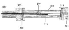
- FIG. 3is a diagram showing a prior art fiber grating strain sensor assembly with a fiber grating prestrained and anchored at both ends.
- FIG. 4is photo of a diamond saw being used to support installation of fiber grating strain and temperature sensors into the I 84 freeway near exit 14 in Oregon.
- FIG. 5is a photo of a fiber grating strain sensor assembly being installed.
- FIG. 6is a photo of a semitrailer whose signature is being measured by fiber grating strain sensors installed on the I-84 freeway near exit 14 in Oregon.
- FIG. 7is a plot of data recorded of two fiber grating strain sensors on the I-84 freeway near exit 14 in Oregon from the semitrailer shown in FIG. 6 .
- the spike signalsmay be used to count axles and axle position to identify the type of truck.
- the position of the two sensors that are separated by approximately 7 feetmay be used to record the truck speed at 57 miles per hour.
- FIG. 8is a diagram of a fiber grating strain sensor installed in the I-84 freeway with one end not attached. Strain signals are generated by motion of the sensing fiber due to friction on the flexing tube.
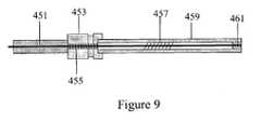
- FIG. 9is an illustration of a fiber grating strain sensor with one anchor point prestrained in a tube.
- FIG. 10is an illustration of a fiber grating strain sensor prestrained in a tube.
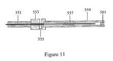
- FIG. 11is an illustration of a fiber grating strain sensor with one end loose in the tube and one anchor point.
- FIG. 12is a diagram showing a fiber grating strain sensor with one end loose in a tube.
- FIG. 13is an illustration showing an assembly with two anchor points.
- the tube containing the fiber grating sensorhas been filled with an adhesive or high viscosity material to insure good coupling between the flexing tube and fiber grating sensor.
- the fiberis attached at one end.
- FIG. 14is an illustration showing an assembly with one anchor point.
- the tube containing the fiber grating sensorhas been filled with an adhesive or high viscosity material to insure good coupling between the flexing tube and fiber grating sensor.
- the fiberis attached at one end.
- FIG. 15is a diagram showing an assembly with a tube filled with an adhesive or high viscosity material to insure good coupling of the fiber optic strain sensor, which is attached at one end.
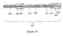
- FIG. 16is an illustration of a fiber grating strain sensor assembly with a fiber grating strain sensor anchored at one end and attached to a spring on the other.
- the assemblyhas two anchor points.
- FIG. 17is a diagram similar to FIG. 16 with one anchor point.
- FIG. 18is an illustration of a fiber grating strain sensor assembly with one end attached to the fixed end of the tube and the other to a spring assembly.
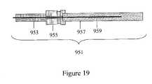
- FIG. 19is an illustration of a fiber grating strain sensor assembly with one anchor point and the fiber grating strain sensor attached to or embedded into a beam that may be composite.
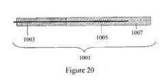
- FIG. 20is a diagram without an anchor point where the fiber lead is integrated into one end of the beam structure.
- the fiber grating strain sensoris attached to or embedded in the beam that may be composite.
- FIG. 21is a diagram showing a fiber grating strain sensor assembly with features similar to FIGS. 8 through 20 where a second fiber grating filter is installed and isolated from strain by a tube that is coated or filled with low viscosity material to minimize friction to the fiber grating filter as the tube assembly flexes.
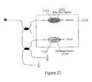
- FIG. 22is an illustration of a vibration sensor that is configured to sense higher frequency vibrations and filter lower frequency vibrations by having the fiber grating sensor attached with a hard material and the fiber grating filter attached with a softer material.
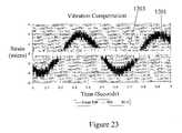
- FIG. 23is a graph showing the response of the fiber grating strain sensor attached via hard material onto the plate filtered through a stationary fiber grating filter not on the plate versus the relative response of the hard and soft material fiber grating sensor/filter pair on the plate.
- FIG. 24is a graph similar to FIG. 23 that has been filtered to suppress high frequency noise. It shows a reduction of low frequency vibration sensitivity of approximately a factor of 30.
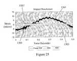
- FIG. 25shows the response to an impact is similar for both the hard material bonded fiber grating sensor on the plate filtered by a fiber grating filter off the plate and the low frequency vibration suppression system.
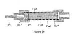
- FIG. 26is a diagram of a moisture/humidity sensor where a fiber grating strain sensor responds to strain induced by swelling of foam encased in a tube.
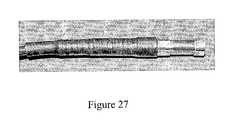
- FIG. 27is a photo of a moisture/humidity sensor constructed according to the diagram of FIG. 26 .
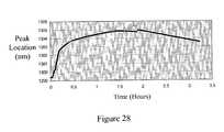
- FIG. 28is a graph of the moisture sensor of FIG. 27 being exposed to water.
- FIG. 29is a graph of the moisture sensor of FIG. 27 being exposed to changes in relative humidity.
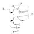
- FIG. 30is a diagram showing a fiber grating humidity sensor with high sensitivity and good thermal compensation by using a fiber grating sensor with a coating responsive to humidity and temperature and a matched fiber grating filter with a coating that responds closely to temperature only.
- FIG. 31is a photo of a sensor constructed according to FIG. 30 .
- FIG. 32is a graph showing the relative humidity response of the sensor of FIG. 30 compared to that of an electrical humidity sensor.
- FIG. 33is a diagram showing a moisture content sensor using a dry air purge.
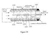
- FIG. 34is a fiber grating moisture content sensor where the fiber grating sensor and fiber grating filter are in a single fiber.
- FIG. 35is a diagram of a fiber grating moisture sensor where the fiber grating sensor and fiber grating filter are in separate fibers and the two are placed in close physical proximity.
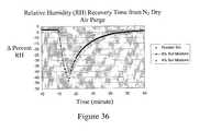
- FIG. 36is a graph illustrating the ability of a fiber grating moisture sensor constructed according to FIG. 35 to measure moisture content associated with 4% and 8% soil moisture content as well as soil flooding.
- FIG. 37is a diagram illustrating means to spatially multiplex the system shown in FIG. 2 .
- FIG. 38is a diagram showing how the spatial multiplexing system of FIG. 37 may be used in a cable to space sensors along a single line.
- FIG. 39is a diagram illustrating means to wavelength division multiplex the system shown in FIG. 2 .
- FIG. 40is a diagram showing how fiber grating strain assemblies may be wavelength division multiplexed.
- FIG. 41shows how a fiber grating strain sensor system may be configured to support traffic monitoring and weigh in motion on a road.
- FIG. 42is a graph illustrating the position dependent response of a fiber grating strain sensor with anchored ends buried in a roadway.
- Fiber grating strain sensorsoffer a series of advantages that include the ability to wavelength encode a series of fiber grating sensors easily into an array on a single fiber with relative ease of fabrication.
- the environmental information sent back by a fiber grating sensoris encoded in wavelength changes that in turn need to be measured by a read out unit in order to accurately interpret environmentally induced changes.
- Many methodscan be used to read out wavelengths including optical spectrum analyzers that are commercially available from Ando, Hewlett Packard and Anritsu, etalon based readout units that are available from Micron Optics and Research International (U.S. Pat. No.
- This prior art systemconsists of a light source 101 that may be a broadband light emitting diode that couples light into an optical fiber end 103 .
- the light in the fiber 105is then coupled into the fiber beamsplitter 107 and a portion of the light is directed into the optical fiber 109 that contains the optical fiber grating 111 .
- a portion of the light beam entering the fiber 109 from the beamsplitter 107is reflected by the fiber grating 111 back to the fiber beamsplitter 107 while the remainder of the light beam propagates toward the fiber end 113 and exits the system.
- a second portion of the light from the fiber beamsplitter 107is directed into the optical fiber 115 and exits the system via the end 117 that is arranged to minimized back reflection.
- the light beam 119 that is reflected off the fiber grating 111is directed back into the fiber beamsplitter 107 and split into the light beams 121 and 123 .
- the light beam 123is directed back into the fiber 105 and towards the light source.
- the light beam 121is directed toward the second fiber beamsplitter 125 and split into the light beams 127 and 129 .
- the light beam 127is then directed toward the filter 131 that might be a fiber grating filter and then falls onto the output detector 135 .
- the light beam 129propagates via the optical fiber 137 to the output detector 139 .
- the wavelength reflected by the fiber grating sensor 111can be determined by taking the ratio of the outputs of the detectors 135 and 139 . This can be done at very high speed, and Blue Road Research has built units operating at up to 10 MHz limited only by the electronics. Sensitivity can be adjusted by appropriately choosing the bandwidth of the filter. That is, as the slope of the filter in terms of intensity versus wavelength changes this will be a key factor in determining sensitivity. For this approach there is a tradeoff between sensitivity and dynamic range dictated by the characteristics of the filter.
- a disadvantage of the readout system of FIG. 1is that since the fiber grating sensor 111 and the filter 131 that may be a fiber grating are not collocated there may be temperature differences that result in a temperature induced error. By collocating the fiber grating sensor and the filter it would be possible to provide a system that would have automatic temperature compensation provided the fiber grating sensor and filter had comparable sensitivity. By selecting the filter to be a fiber grating matched in terms of thermal characteristics to the fiber grating sensor this may be achieved.
- FIG. 2shows the basic layout of this type of system. It shares characteristics of readout systems described by Eric Udd and Tim Clark in U.S. Pat. No. 5,380,995 for example FIG. 21 in that patent. The major differences are that a second detector has been added to correct for amplitude fluctuations in the system and the fiber grating sensor and filter have been collocated spatially to insure the best possible temperature compensation.
- a light source 201that may be a broadband light source such as a light emitting diode or fiber light source is used to inject a light into the fiber end 203 .
- the resulting light beam 205propagates along the optical fiber segment 207 to the fiber beamsplitter 209 .
- the light beam 205is split into the two light beams 211 and 213 .
- the light beam 211propagates along the optical fiber 215 to the fiber grating sensor 217 .
- a portion of light beam 211is reflected by the fiber grating sensor 217 as the light beam 219 whose wavelength is dependent on the environmentally induced state of the fiber grating 217 .
- the other portion of the light beam 219propagates past the fiber grating 217 and exits the system via the antireflecting end 221 .
- the light beam 213exits the system via the antireflecting end 223 .
- the light beam 219 that is reflected from the fiber grating sensor 217propagates back to the fiber beamsplitter 209 .
- a portion of the light beam 219is split into the light beam 225 that is directed back toward the light source 201 .
- the second portion of the light beam 219is split into the light beam 227 , which propagates along the optical fiber segment 229 to a second fiber beamsplitter 231 .
- the light beam 229is split into the light beam 233 that propagates to the fiber grating filter 237 that may be located in close proximity to the fiber grating sensor 217 to minimize thermal sensitivity.
- a portion of the light beam 233is reflected off the fiber grating filter 237 as the light beam 241 and a portion passes through the fiber grating filter 237 and exits the system via the nonreflecting end 239 .
- the other part of the light beam 229is split into the light beam 235 and directed via the optical fiber segment 245 to the output detector 247 .
- the light beam 241 reflected off the fiber grating filter 237enters the coupler 231 and a portion is directed as the new light beam 249 via the optical fiber segment 251 to the output detector 253 .
- the wavelength change of the fiber grating sensor 217may be determined and if the fiber grating filter 237 is collocated with the fiber grating sensor 217 and the fiber gratings 237 and 217 are thermally matched, temperature effects on the system can be greatly reduced.
- the beamsplitter 209could be replaced by a optical circulator with one port of the circulator connected to the light source, the second port connected to the fiber grating sensor 217 , the third port connected to the fiber 229 .
- An application where highly sensitive fiber grating strain sensors are neededinvolves the measurement of strain fields associated with cars and trucks passing over roadways or other paved surfaces.
- existing systems based on piezoelectric devicesare mounted near the surface of the road and damage associated with traffic near the surface results in their failure over periods of approximately one year.
- a fiber optic microbend based systemwas tried by the Oregon Department of Transportation that was mounted near the surface of the roadway and it lasted approximately two weeks before failure.
- the systemshould be sensitive enough that it could be embedded approximately 3 inches into the roadbed and have sufficiently high sensitivity to measure the position of truck axles for identification and speed determination.
- Accurate measurement of strain in the freewayalso could be used to support weigh in motion systems. By burying the fiber sensors 3 inches into the freeway the concrete could wear down 2 inches at which point the surface would be scheduled for routine replacement and the sensors would be sufficiently deep to survive the process.
- An optical fiber 301is cemented and or crimped in place at the location 303 of the anchor assembly 305 that is notched to accommodate anchoring in concrete of asphalt like materials such as hot sealant used in road construction.
- a fiber grating 307is located in the optical fiber 301 and placed in a tube 309 that is attached to the anchor 303 and the anchor 311 .
- the fiber 301 inside the tube 309 with the fiber grating 307is prestrained and cemented and or crimped in the anchor 311 at the location 313 .
- a second fiber grating 315may be placed in the region of the tube and unstrained to measure temperature.
- FIG. 4shows a diamond blade cutter being used to cut 3 inch deep grooves on the I-84 freeway east of Portland, Oreg. near exit 14 in order to install a set of four fiber grating strain sensors similar to those shown in FIG. 3 .
- FIG. 5shows a sensor being installed in the I-84 freeway.
- FIG. 6shows a semi trailer with two front axles and three back axles passing over the set of fiber grating strain sensors on the I-84 freeway.
- FIG. 7shows the response of two of the sensors spaced by approximately 7 feet. The spikes corresponding to the two front axles and three back axles can clearly be seen on both of the fiber grating sensor outputs and used to identify the characteristics of a semitrailer passing. The time spacing between the arrival of the first axle on the sensors spaced by 7 feet can be used to determine the speed of the truck at 57 miles per hour.
- FIG. 9shows a variation of the basic design in FIG. 8 .
- the fiber 451is anchored by the assembly 453 on one end by cementing in place and or crimping at location 455 .
- the fiber grating 457is prestrained in the tube 459 and potted in place at the end of the tube 461 .
- FIG. 10shows the fiber 501 being cemented in the tube 503 at the locations 505 and 507 after the fiber grating sensor 509 is prestrained in the tube 503 .
- FIG. 11shows a variation on FIG. 8 where the fiber 551 is anchored at the location 553 by the anchor assembly 555 .
- the fiber grating sensor 557is placed in the tube 559 and sealed at the other end 561 .
- FIG. 12shows a variation of FIG. 3 where the fiber 601 contains a fiber grating sensor 603 that is potted on one end of the tube 605 at the location 607 and the other end of the tube 605 is sealed at location 609 .
- FIG. 7shows changes to the baseline of operation.
- One way to improve this situationis to apply an adhesive to the interior to the tubing or apply the adhesive to the fiber grating region before it is pulled into the region of the tube.
- Another alternativeis to fill the tube with a viscous elastic material.
- FIG. 13shows this type of configuration.
- a fiber 651is anchored by cementing and or crimping by the anchor assembly 653 at the location 655 .
- the tube 656contains the fiber grating sensor 657 that is immersed in the fluid-like adhesive 659 which is sealed on the end 661 by the anchor assembly 663 .
- FIG. 14shows an assembly similar to that of FIG. 13 without the second anchor assembly 663 .
- the fiber 701is anchored at the location 703 by the anchor assembly 705 and placed in the tube 707 that contains the fiber grating sensor 709 and the fluid like adhesive 711 .
- the other end of the tube 707is sealed at the other end of the tube 713 .
- FIG. 15shows an assembly where the optical fiber 751 is cemented in place at the location 753 in a tube 755 .
- Interior to the tube 755is a fiber grating sensor 757 in a fluid adhesive 759 .
- the tubeis sealed at the other end 761 .
- FIG. 16shows a fiber grating strain sensor transducer 801 consisting of an optical fiber 803 that is cemented and or crimped in the location 805 of the anchor assembly 807 .
- a fiber grating 809is written into the optical fiber 803 which has an end attached to a spring 813 via the clamping end 815 .
- This assemblyis placed in the tube 817 that is in turn attached to the anchor assemblies 807 and 819 .
- the other end of the spring 813is preloaded and attached to the anchor assembly in the area 820 .
- the advantage of the spring-loaded approachis that by appropriate choice of spring or spring like material replacing the spring (such as an elastic material) the loading on the fiber can be adjusted to optimize response for a variety of displacements.
- FIG. 17shows an assembly 851 similar to FIG. 16 with the second end of the spring 853 anchored in the tube 855 in the location 857 .
- FIG. 18shows an assembly 901 similar to FIG. 16 where the tube 903 anchors the one end of the optical fiber 905 at the location 907 and the other end of the optical fiber 905 is anchored at 909 attaching one end of the spring 911 .
- the other end of the spring 911is anchored in the tube at the point 913 .
- FIG. 19shows one type of transducer 951 of this type.
- An optical fiber 953is placed into a connection assembly 955 , which acts an interface and buffer to the composite beam 957 that has a fiber grating sensor 959 attached to it.
- the thirdis to embed the fiber grating into the composite part either directly into its layers or by bonding overlay material on top of it.
- the fourth methodis to embed or attach a fiber grating prestrained in a tube to the beam, which may be a composite beam. The choice of method used depends on the type of installation on which it is used. Embedding it into the composite part or using the groove techniques provides the most protection when installation conditions are severe, handling may be rough and installation time short such as on an operating freeway where minimizing lane closure is important.
- FIG. 20illustrates a composite beam transducer 1001 where the optical fiber 1003 containing the fiber grating sensor 1005 is attached or embedded directly into the composite beam 1007 .
- the fiber grating sensormay have thermally induced wavelength shift that detune the system from optimal response. This can be compensated for by tuning the fiber grating filter mechanically. This can be done by axially stretching the optical fiber or using a bending beam approach such as that described by Schulz and Udd in U.S. patent application Ser. No. 09/746,037 so that the position of the fiber grating filter is optimized.
- One issue with this approachis that it requires active thermal compensation that may require additional power to drive a mechanical mechanism such as a stepper motor.
- FIG. 2An alternative approach is to use the configuration of FIG. 2 where matched filters that may be fiber gratings are placed without strain or at reduced strain in the transducer assemblies of FIGS. 8 through 20 . Since the fiber grating filter is in the same assembly there is passive thermal matching. Partial strain isolation may be achieved by assuring the fiber is loose in the assembly, a second step would be to coat the fiber with a friction reducing lubricant or float the fiber in a low viscosity material.
- FIG. 21illustrates the passive thermal compensation approach with a fiber grating sensor matched to a fiber grating filter placed in essentially the same thermal environment.
- the transducer 1051consists of an optical fiber 1053 that is cemented or crimped at the anchor 1055 at the end 1057 .
- the fiber grating 1059is placed under tension and the second end of the fiber 1053 cemented or crimped to the second anchor 1061 at the location 1063 .
- the fiberis placed under tension so that it can respond to both tension and compression loads.
- a second fiber 1065passes through the anchor 1055 and strain isolated such as in a tube 1069 that encloses the fiber grating filter 1071 .
- the tube 1069is designed so that friction is minimized between the fiber grating 1071 and the interior of the tube 1069 . Using lubricants such as silicon oil could do this. Also the exterior to the tube 1069 could be lubricated to minimize friction between it and the protective tube 1073 that is in turn attached to the anchors 1055 and 1061 . The end result would be to provide a means to doubly isolate the fiber grating filter 1071 from motions of the tube 1073 .
- FIG. 22illustrates how this can be done using the basic configuration described in detail in association with FIG. 2 .
- the fiber grating sensor 1151is bonded to an aluminum plate 1153 with a hard epoxy such as the commercial blue dye epoxy 1155 associated with fabrication of fiber connectors.
- the fiber grating filter 1157is attached to the aluminum plate 1153 with the relatively soft urethane epoxy 1159 .
- the aluminum plateswas then subject to low frequency vibration and results compared for the output of the fiber grating sensor 1151 when it was hooked up to a readout unit with a fiber grating filter external to the plate curve 1201 of FIG.
- FIG. 23shows the same signals filtered to 100 Hz.
- the curve 1251corresponds to the fiber grating filter 1157 being external to the aluminum plate 1153 and curve 1253 corresponds to the fiber grating filter 1157 being bonded with the urethane epoxy 1159 to the aluminum plate 1153 . Note that there is nearly a factor of 30 reduction in low frequency vibration sensitivity.
- FIG. 25shows the result when the aluminum plate 1153 is struck with an impact.
- the curve 1301corresponds to the externally located fiber grating filter 1157 and the curve 1303 corresponds to the fiber grating filter 1157 located on the aluminum plate 1153 . When an impact occurs the effect can be seen in the region of 1305 for curve 1301 and region 1307 for curve 1303 .
- the magnitude of the impact signal in both casesis approximately equal.
- FIG. 26illustrates a basic configuration.
- An optical fiber 1351is cemented or crimped on one end 1353 of an anchor 1355 .
- a fiber grating sensor 1357is stretched between the points 1353 and 1359 under tension.
- a porous tube or spring assembly 1361contains a material 1363 that expands in the presence of water. The expansion of the material 1363 cause the tube 1361 to be stretched axially which in turn stretches the fiber grating sensor 1357 .
- FIG. 27shows a transducer built according the design of FIG.
- FIG. 28shows the response when this sensor is placed in water while FIG. 29 shows its response to relative humidity.
- a notable feature of the transducer shown in FIG. 28is that it has a very large response in terms of wavelength shift greatly reducing requirements on a read out unit.
- a very broadband filterthat is thermally stabilized such as a chirped fiber grating on mounted on thermally compensated ceramic in a configuration similar to FIG. 1 is adequate.
- FIG. 30A basic configuration similar to that described in FIG. 2 is used.
- the fiber grating sensor 1401is matched to a fiber grating filter 1403 .
- the two gratingsare slightly offset in wavelength so that small relative changes in wavelength result in large net amplitude changes on the output detector 1409 .
- the fiber grating sensor 1401is coated with a material 1405 that expands and contracts with relative humidity, this material may be polyimide.
- the fiber grating filter 1403is coated with a material 1407 that is relatively insensitive to humidity but responds in a manner similar to the fiber grating sensor 1401 /coating 1405 .
- the material 1407could be an epoxy acrylate that has similar thermal response to polyimide but is relatively insensitive to humidity.
- FIG. 31shows a photograph of a humidity sensor package where the fiber grating sensor 1401 with a polyimide coating is placed in close proximity to the fiber grating filter 1403 with an epoxy acrylate coating.
- FIG. 32shows a comparison between the fiber grating relative humidity sensor designed according to the block diagram of FIG. 30 compared to an electrical sensor. From approximately 20 to 80 percent relative humidity the responses are within about 2% of each other. The discrepancies are believed to be due at least in part to nonuniformities in the polyimide coating on the fiber grating sensor.
- FIG. 33shows a system that is being used to measure these higher percentages of moisture.
- a dry air source 1501is used to pump air into a tube 1503 with humidity sensors 1505 spaced along the length of the tube 1503 in locations adjacent to air permeable membranes 1507 .
- the dry airis used to purge the tube the sensors and tube are dried. After the purging has stopped the evaporating moisture from the soil 1509 causes a rise in humidity in the tube 1503 over time.
- a spacer 1511is used to hold the humidity sensor 1505 in a fixed position in the tube 1503 . The rate of the rise in relative humidity can be used to gage the percentage of moisture content in the soil 1509 .
- FIG. 34shows the case where the humidity sensor 1505 consists of a fiber grating sensor 1551 that is responsive to humidity and temperature via a coating 1553 that may be polyimide and in the same optical fiber 1559 a second fiber grating sensor 1555 that is responsive primarily to temperature via the action of the coating 1557 that may be epoxy acrylate.
- the fiber 1559is held in a fixed position in the tube 1561 by the spacer 1563 .
- the actions of the sensors 1551 and 1555are compared in wavelength to enable a temperature insensitive measurement.
- FIG. 35shows an alternative configuration where a fiber grating sensor 1601 is placed in the optical fiber 1603 and coated with a material 1605 sensitive to humidity changes that may be polyimide.
- a second fiber 1607contains a second fiber grating sensor 1609 is placed in close proximity to the fiber grating sensor 1601 .
- the fiber grating sensor 1609has a coating 1611 that has a temperature response similar to that of the coating 1605 but has minimal humidity response that may be epoxy acrylate.
- a dry air source 1613is used to flow dry air through the tube 1615 and out the free open end drying the sensors.
- the relative humidity in the tube 1615is increased and response of the sensors 1601 and 1609 is a function of the soil moisture content. Spacing elements 1619 and 1621 are used to hold the optical fibers 1603 and 1607 in a fixed position in the tube.
- the readout of the humidity sensor of FIG. 35may be performed by virtually any appropriate wavelength measurement device including optical spectrometers, scanning etalons or the readout approach described in association with FIG. 2 .
- the output of the fiber grating sensor 1601 that depends on both humidity and temperature due to its coating 1605can be compensated by the similar fiber grating sensor 1609 whose coating 1611 depends very nearly only on temperature.
- FIG. 36shows the output of a sensor constructed according to FIG. 35 when placed in soil with content of 4% and 8% moisture as well as the case where the soil is flooded.
- the sensoris air purged during each run causing the falling slopes seen in FIG. 36 .
- the rising slopes of humidityvary clearly depending on water content allowing the percentage of moisture in the soil to be determined.
- the fiber grating transducers that have been described earlier in this patentcan all be multiplexed and read out using such methods as wavelength; time division and spatial multiplexing and the wavelength measured using standard readout units. However in many cases higher speed, and or sensitivity may be required.
- the read out approach of FIG. 2can operate at speeds up to GHz, although for practical reasons associated with mechanical resonance's of optical fiber, rates that exceed 10 s of MHz would be unlikely to be used.
- the approachalso allows closely matched fiber gratings with steep spectral slopes to be used; enabling high sensitivity and appropriate matching and location achieve thermal compensation.
- FIG. 37shows a means of using spatial multiplexing with the configuration associated with FIG. 2 .
- a light source 1651that may be a fiber light source, a superradiant diode or a light emitting diode couples into the end 1653 of a multi-output port coupler 1655 .
- the coupler 1655could have N output ports although in the case of FIG. 37 it has three.
- the three outputssupport a series of sensor readout combinations 1657 , 1659 and 1661 that act in a manner analogous to the system described in FIG. 2 .
- the fiber grating sensor pairscan be placed so that they measure a variety of environmental effects including high speed strain in a roadway or paved surface or moisture content in soil.
- One fiber grating sensorcould be optimized for the desired environmental effect plus temperature while the function of the other fiber grating sensor could be used for temperature compensation.
- FIG. 38shows how the sensor pairs 1663 , 1665 and 1667 could be arranged in a single cable assembly 1669 so that they sense environmental effects at specific locations along a cable. Since the fibers used are quite small having large numbers of fibers in a single fiber cable is quite practical for many applications. The very low cost of optical fiber can make this an attractive economic alternative for certain applications.
- FIG. 39show a method of wavelength division multiplexing the system of FIG. 2 .
- a light source 1701couples light into the fiber end 1703 to generate a light beam 1705 that is split by a fiber coupler 1709 into two light beams 1709 and 1711 .
- the light beam 1711propagates out of system at the port 1713 .
- the other light beam 1707propagates past the fiber grating sensors 1715 , 1717 and 1719 with center wavelengths at ⁇ 1 , ⁇ 2 , ⁇ 3 respectively which each reflect light beams wavelength encoded that are representative of environmental effects in their location.
- These reflected light beams 1721propagate back to the fiber coupler 1707 and a portion of the light beams 1721 is directed as the light beam 1723 to the second fiber coupler 1725 .
- a portion of the light beam 1723is split by the coupler 1725 as the light beam 1727 , which is directed to the output reference detector 1729 that is used to monitor the overall light levels in the system.
- the second part of the light beam 1731is directed toward the fiber grating filters 1733 , 1735 and 1737 centered about the wavelengths ⁇ 1 , ⁇ 2 , ⁇ 3 that are used to modulate the fiber grating sensor signals to determine wavelength in a manner similar to that associated with FIG. 2 .
- the modulated reflected light beam 1739is directed back to the fiber coupler 1725 and a portion of this light beam 1741 is directed into a wavelength division multiplexing element 1743 used to sort out the wavelengths ⁇ 1 , ⁇ 2 , ⁇ 3 to the corresponding output detectors 1745 , 1747 and 1749 .
- FIG. 40is an illustration of how wavelength division multiplexing can be used to support two compensated fiber grating sensor assemblies in line.
- the assembly 1801has a fiber grating sensor 1803 matched to a fiber grating filter 1805 both with a nominal operating wavelength in the region of ⁇ 1 .
- the assembly 1807has a fiber grating sensor 1809 matched to a fiber grating filter 1811 in the region of an operating wavelength ⁇ 2 . Additional sensor assemblies could be multiplexed in line in a similar manner.
- FIG. 41shows a layout used to support weigh in motion.
- the line of sensors 1907contains two sensor assemblies 1911 and 1913 , which are offset from the two sensor assemblies 1915 and 1916 .
- Wavelength division or spatial multiplexing or other multiplexing methodssuch as time division multiplexing may multiplex the sensors in the lines 1907 and 1909 .
- the offsetsmay be necessary because the response of the sensors may be position dependent.
- FIG. 42illustrates a representative response curve for a fiber sensor similar to that of FIG. 3 when placed at a depth of 3 inches into concrete. The sensor is most responsive in between the two anchor points and falls off toward each anchor point.
- the two offset sensor lines 1907 and 1909allow determination of both the wheel position to allow a correction factor for the actual weight of the vehicle.
Landscapes
- Physics & Mathematics (AREA)
- General Physics & Mathematics (AREA)
- Optical Transform (AREA)
- Length Measuring Devices By Optical Means (AREA)
Abstract
Description
Claims (16)
Priority Applications (1)
| Application Number | Priority Date | Filing Date | Title |
|---|---|---|---|
| US10/325,874US7038190B2 (en) | 2001-12-21 | 2002-12-20 | Fiber grating environmental sensing system |
Applications Claiming Priority (2)
| Application Number | Priority Date | Filing Date | Title |
|---|---|---|---|
| US34291401P | 2001-12-21 | 2001-12-21 | |
| US10/325,874US7038190B2 (en) | 2001-12-21 | 2002-12-20 | Fiber grating environmental sensing system |
Publications (2)
| Publication Number | Publication Date |
|---|---|
| US20030127587A1 US20030127587A1 (en) | 2003-07-10 |
| US7038190B2true US7038190B2 (en) | 2006-05-02 |
Family
ID=26985153
Family Applications (1)
| Application Number | Title | Priority Date | Filing Date |
|---|---|---|---|
| US10/325,874Expired - LifetimeUS7038190B2 (en) | 2001-12-21 | 2002-12-20 | Fiber grating environmental sensing system |
Country Status (1)
| Country | Link |
|---|---|
| US (1) | US7038190B2 (en) |
Cited By (36)
| Publication number | Priority date | Publication date | Assignee | Title |
|---|---|---|---|---|
| US20030223757A1 (en)* | 2002-06-03 | 2003-12-04 | Takashi Yamamoto | Standard radio frequency signal generating method and standard radio frequency signal generating device |
| US20050206526A1 (en)* | 2004-03-17 | 2005-09-22 | Yoshihiro Ozawa | Road-ice detecting sensor, method for installing same, and road-ice detecting method |
| US20070265503A1 (en)* | 2006-03-22 | 2007-11-15 | Hansen Medical, Inc. | Fiber optic instrument sensing system |
| US20080218770A1 (en)* | 2007-02-02 | 2008-09-11 | Hansen Medical, Inc. | Robotic surgical instrument and methods using bragg fiber sensors |
| US20080285909A1 (en)* | 2007-04-20 | 2008-11-20 | Hansen Medical, Inc. | Optical fiber shape sensing systems |
| US20090137952A1 (en)* | 2007-08-14 | 2009-05-28 | Ramamurthy Bhaskar S | Robotic instrument systems and methods utilizing optical fiber sensor |
| EP2073000A1 (en) | 2007-12-20 | 2009-06-24 | Nederlandse Organisatie voor toegepast- natuurwetenschappelijk onderzoek TNO | Coated waveguide for optical detection |
| EP2075549A1 (en) | 2007-12-28 | 2009-07-01 | Nederlandse Organisatie voor toegepast- natuurwetenschappelijk onderzoek TNO | Shape memory sensor |
| EP2202548A1 (en) | 2008-12-23 | 2010-06-30 | Nederlandse Organisatie voor Toegepast-Natuurwetenschappelijk Onderzoek TNO | Distributed optical chemical sensor |
| CN102095537A (en)* | 2011-02-16 | 2011-06-15 | 南京航空航天大学 | Fiber grating pressure sensor, manufacture method and method for monitoring load of asphalt pavement |
| US20110243185A1 (en)* | 2009-09-30 | 2011-10-06 | Fasten Group Company, Ltd. | Bridge Intelligent Cable System with Built-In Fiber Grating Sensor |
| CN102252791A (en)* | 2011-07-06 | 2011-11-23 | 西南交通大学 | Differential pair grating demodulating technology for fiber grating sensor stress measurement |
| EP2500314A1 (en) | 2011-03-14 | 2012-09-19 | Nederlandse Organisatie voor toegepast -natuurwetenschappelijk onderzoek TNO | Photonic crystal sensor |
| CN102809454A (en)* | 2012-06-29 | 2012-12-05 | 山东大学 | FBG (Fiber Bragg Grating) force measuring anchor rod and using method |
| CN103759652A (en)* | 2014-01-17 | 2014-04-30 | 哈尔滨工业大学 | Two-dimensional microscale measuring device and method based on double fiber bragg gratings |
| US8780339B2 (en) | 2009-07-15 | 2014-07-15 | Koninklijke Philips N.V. | Fiber shape sensing systems and methods |
| RU2531657C2 (en)* | 2012-12-25 | 2014-10-27 | Федеральное государственное бюджетное образовательное учреждение высшего профессионального образования "Казанский национальный исследовательский технический университет им. А.Н. Туполева-КАИ" (КНИТУ-КАИ) | On-board device of fuel quality assessment |
| US8989528B2 (en) | 2006-02-22 | 2015-03-24 | Hansen Medical, Inc. | Optical fiber grating sensors and methods of manufacture |
| CN104535234A (en)* | 2014-12-29 | 2015-04-22 | 大连理工大学 | Optical fiber inhaul cable prestress monitoring method and sensor thereof |
| US20150146192A1 (en)* | 2012-06-05 | 2015-05-28 | Technische Universität München | Optical measurement system with polarization compensation, and corresponding method |
| US20150268096A1 (en)* | 2012-10-23 | 2015-09-24 | Eric Udd | Fiber grating sensor system for measuring key parameters during high speed |
| WO2015183090A1 (en) | 2014-05-28 | 2015-12-03 | Nederlandse Organisatie Voor Toegepast-Natuurwetenschappelijk Onderzoek Tno | A fiber bragg grating optical sensor having a nanoporous coating |
| US9358076B2 (en) | 2011-01-20 | 2016-06-07 | Hansen Medical, Inc. | System and method for endoluminal and translumenal therapy |
| CN105756104A (en)* | 2016-03-10 | 2016-07-13 | 青岛理工大学 | Indoor model pile body fiber grating and pile-soil interface sensor laying device |
| CN105780821A (en)* | 2016-03-10 | 2016-07-20 | 青岛理工大学 | Indoor model pile body fiber grating and pile-soil interface sensor laying device |
| US20160223414A1 (en)* | 2011-05-04 | 2016-08-04 | Agency For Science, Technology And Research | Fiber bragg grating (fbg) sensor |
| CN106639158A (en)* | 2016-11-16 | 2017-05-10 | 广西大学 | Integrated intelligent anchorage device and manufacturing method thereof |
| CN107817065A (en)* | 2017-09-28 | 2018-03-20 | 中北大学 | A kind of compact detonation pressure measuring system based on bragg grating |
| CN107843273A (en)* | 2017-10-27 | 2018-03-27 | 周燕红 | A kind of fiber optic loop sensor-based system and implementation method |
| US10130427B2 (en) | 2010-09-17 | 2018-11-20 | Auris Health, Inc. | Systems and methods for positioning an elongate member inside a body |
| DE102017011730A1 (en)* | 2017-12-18 | 2019-06-19 | Hottinger Baldwin Messtechnik Gmbh | Interrogator for two fiber Bragg grating measuring points |
| WO2019213759A1 (en)* | 2018-05-08 | 2019-11-14 | Hifi Engineering Inc. | Optical fiber assembly |
| US10667720B2 (en) | 2011-07-29 | 2020-06-02 | Auris Health, Inc. | Apparatus and methods for fiber integration and registration |
| US10697825B2 (en) | 2017-07-12 | 2020-06-30 | Fbs, Inc. | Omnidirectional optical fiber Bragg gratings for ultrasonic guided wave sensing and associate source location methods |
| US20200355575A1 (en)* | 2017-11-08 | 2020-11-12 | Commissariat A L'energie Atomique Et Aux Energies Alternatives | Structural health monitoring for an industrial structure |
| US11037382B2 (en)* | 2018-11-20 | 2021-06-15 | Ford Global Technologies, Llc | System and method for evaluating operation of environmental sensing systems of vehicles |
Families Citing this family (47)
| Publication number | Priority date | Publication date | Assignee | Title |
|---|---|---|---|---|
| US7154081B1 (en) | 2002-11-26 | 2006-12-26 | Luna Innovations Incorporated | Composite structures, such as coated wiring assemblies, having integral fiber optic-based condition detectors and systems which employ the same |
| NO20032119D0 (en)* | 2003-05-12 | 2003-05-12 | Nexans | Monitoring Cable |
| EP1704407B1 (en)* | 2003-10-24 | 2013-05-08 | Troxler Electronic Laboratories, Inc. | Asphalt microwave density measurement method |
| US20050201664A1 (en)* | 2004-03-12 | 2005-09-15 | Eric Udd | Fiber grating pressure wave speed measurement system |
| JP4361515B2 (en)* | 2005-06-07 | 2009-11-11 | 日立電線株式会社 | Optical fiber sensor and manufacturing method thereof |
| US20070116402A1 (en)* | 2005-06-30 | 2007-05-24 | Infoscitex Corporation | Humidity sensor and method for monitoring moisture in concrete |
| US20070058898A1 (en)* | 2005-06-30 | 2007-03-15 | Infoscitex | Humidity sensor and method for monitoring moisture in concrete |
| US20070065071A1 (en)* | 2005-06-30 | 2007-03-22 | Infoscitex | Humidity sensor and method for monitoring moisture in concrete |
| FR2903773B1 (en)* | 2006-07-13 | 2009-05-08 | Bidim Geosynthetics Soc Par Ac | DEVICE, SYSTEM AND METHOD FOR DETECTING AND LOCATING DYSFUNCTION IN A HYDRAULIC WORK, AND A HYDRAULIC WORK EQUIPPED WITH SAID DEVICE. |
| DE102006049325B4 (en)* | 2006-10-19 | 2010-04-22 | Siemens Ag | Arrangement for monitoring a stressed body and method for its production |
| US20090028489A1 (en)* | 2007-07-17 | 2009-01-29 | Eric Udd | High speed fiber optic grating sensor system |
| CN101983325B (en) | 2008-03-31 | 2013-04-24 | 维斯塔斯风力系统集团公司 | Optical transmission strain sensor for wind turbines |
| US7646944B2 (en)* | 2008-05-16 | 2010-01-12 | Celight, Inc. | Optical sensor with distributed sensitivity |
| GB2461532A (en)* | 2008-07-01 | 2010-01-06 | Vestas Wind Sys As | Sensor system and method for detecting deformation in a wind turbine component |
| GB2461566A (en)* | 2008-07-03 | 2010-01-06 | Vestas Wind Sys As | Embedded fibre optic sensor for mounting on wind turbine components and method of producing the same. |
| GB2463696A (en)* | 2008-09-22 | 2010-03-24 | Vestas Wind Sys As | Edge-wise bending insensitive strain sensor system |
| GB2466433B (en) | 2008-12-16 | 2011-05-25 | Vestas Wind Sys As | Turbulence sensor and blade condition sensor system |
| US8200049B2 (en)* | 2009-05-14 | 2012-06-12 | Celight, Inc. | Optical sensor for detecting and localizing events |
| US8280202B2 (en)* | 2009-05-14 | 2012-10-02 | General Electric Company | Fiber-optic dynamic sensing modules and methods |
| GB2472437A (en) | 2009-08-06 | 2011-02-09 | Vestas Wind Sys As | Wind turbine rotor blade control based on detecting turbulence |
| GB2477529A (en) | 2010-02-04 | 2011-08-10 | Vestas Wind Sys As | A wind turbine optical wind sensor for determining wind speed and direction |
| CN102393359A (en)* | 2011-10-18 | 2012-03-28 | 大连理工大学 | Fiber bragg grating temperature sensor |
| CN104011508B (en)* | 2011-12-20 | 2016-11-02 | 洛桑联邦理工学院 | Optical Fiber Sensing System Based on Bragg Grating and Optical Time Domain Reflectometer |
| ITBO20130135A1 (en)* | 2013-03-28 | 2014-09-29 | Filippo Bastianini | DEFORMATION SENSOR WITH BRAGG FIBER OPTICAL RETICLE, THERMOCOMPENSED, IMPACT RESISTANCE, WITH ADJUSTABLE SENSITIVITY AND ADJUSTABLE FLANGES |
| WO2015069623A1 (en)* | 2013-11-08 | 2015-05-14 | United Technologies Corporation | Fiber grating temperature sensor |
| FR3016971B1 (en)* | 2014-01-24 | 2017-05-26 | Office Nat D Eudes Et De Rech Aerospatiales | HIGH BRILLOIN THRESHOLD OPTICAL FIBER DEVICE AND METHOD OF MANUFACTURING SUCH A DEVICE |
| CN103900491B (en)* | 2014-03-20 | 2017-01-11 | 哈尔滨工业大学 | Device and method for measuring three-core optical fiber space shape based on stimulated Brillouin principle |
| DE102014223639B3 (en)* | 2014-11-19 | 2016-03-31 | Siemens Aktiengesellschaft | Method for mounting a fiber optic sensor in a protective tube and fiber optic sensor with a protective tube |
| CA3005838C (en) | 2015-11-18 | 2022-06-07 | Corning Optical Communications LLC | System and method for monitoring strain in roadway optical cable |
| CN105806374B (en)* | 2016-05-06 | 2019-02-26 | 深圳市畅格光电有限公司 | A kind of demodulation method of optic fiber grating wavelength |
| CN105738268B (en)* | 2016-05-10 | 2017-06-16 | 河海大学 | Hydraulic Projects observed seepage behavior Integrated Monitoring System and monitoring method under complex environment |
| CN106640907A (en)* | 2016-11-16 | 2017-05-10 | 广西大学 | Intelligent nut capable of distributed measurement and manufacturing method thereof |
| US10407838B1 (en)* | 2017-02-06 | 2019-09-10 | Integrated Roadways, Llc | Modular pavement slab |
| CN108168586A (en)* | 2018-02-07 | 2018-06-15 | 濮阳光电产业技术研究院 | A kind of fiber grating humiture integrative sensor |
| NL2020869B1 (en)* | 2018-05-03 | 2019-11-12 | Fugro Tech Bv | A body for holding a fiber optic strain sensor, a system including the body, and a method for determining strain in an object. |
| CN108760603A (en)* | 2018-07-10 | 2018-11-06 | 湖北文索光电科技有限公司 | Series distributed optical fiber geological stability safety monitoring sensor and system |
| WO2021041605A1 (en)* | 2019-08-30 | 2021-03-04 | Luna Innovations Incorporated | One or more fiber optic sensors locally bonded with a flexible filament structure |
| CN111764893B (en)* | 2020-07-07 | 2023-03-03 | 中煤科工集团西安研究院有限公司 | Coal mine underground horizontal deep hole fiber bragg grating strain sensor arrangement device and construction method thereof |
| CN111721227A (en)* | 2020-07-13 | 2020-09-29 | 大连大学 | A monitoring and early warning system for slope bolt based on LabVIEW and FBG strain sensor |
| CN112816054B (en)* | 2020-12-30 | 2022-12-27 | 北京航天控制仪器研究所 | Fiber laser microphone of dysmorphism spring sensitization structure |
| CN113390778B (en)* | 2021-06-29 | 2024-11-26 | 大连理工大学 | A fiber optic sensor with temperature compensation for monitoring internal corrosion of oil and gas pipelines |
| US11823567B2 (en)* | 2021-08-04 | 2023-11-21 | Xerox Corporation | Traffic monitoring using optical sensors |
| US12352643B2 (en)* | 2021-08-04 | 2025-07-08 | Xerox Corporation | Traffic monitoring using optical sensors |
| US11782231B2 (en) | 2021-08-04 | 2023-10-10 | Xerox Corporation | Installation of optical sensors for use in traffic monitoring |
| CN113932838B (en)* | 2021-10-22 | 2023-09-19 | 深圳市畅格光电有限公司 | High-precision fiber bragg grating demodulator and demodulation method thereof |
| CN114137451B (en)* | 2021-11-30 | 2023-09-26 | 哈尔滨理工大学 | MXene and GMM coated fiber optic sensor for humidity and magnetic field measurement |
| CN116363852B (en)* | 2022-12-12 | 2025-03-28 | 中国科学院电工研究所 | In-situ monitoring system for motor composite components based on optical fiber sensing |
Citations (6)
| Publication number | Priority date | Publication date | Assignee | Title |
|---|---|---|---|---|
| US5380995A (en) | 1992-10-20 | 1995-01-10 | Mcdonnell Douglas Corporation | Fiber optic grating sensor systems for sensing environmental effects |
| US5397891A (en) | 1992-10-20 | 1995-03-14 | Mcdonnell Douglas Corporation | Sensor systems employing optical fiber gratings |
| US6125216A (en)* | 1997-06-19 | 2000-09-26 | British Aerospace Public Limited Company | Strain isolated optical fibre bragg grating sensor |
| US6335524B1 (en) | 1997-10-22 | 2002-01-01 | Blue Road Research | High speed demodulation systems for fiber optic grating sensors |
| US6600149B2 (en) | 1999-12-27 | 2003-07-29 | Whitten L. Schulz | Fiber grating environmental sensing system |
| US6788835B2 (en)* | 1999-04-02 | 2004-09-07 | Ifos, Inc. | Multiplexable fiber-optic strain sensor system with temperature compensation capability |
- 2002
- 2002-12-20USUS10/325,874patent/US7038190B2/ennot_activeExpired - Lifetime
Patent Citations (9)
| Publication number | Priority date | Publication date | Assignee | Title |
|---|---|---|---|---|
| US5380995A (en) | 1992-10-20 | 1995-01-10 | Mcdonnell Douglas Corporation | Fiber optic grating sensor systems for sensing environmental effects |
| US5397891A (en) | 1992-10-20 | 1995-03-14 | Mcdonnell Douglas Corporation | Sensor systems employing optical fiber gratings |
| US5627927A (en) | 1992-10-20 | 1997-05-06 | Mcdonnell Douglas Aerospace West | Fiber with multiple overlapping gratings |
| US6125216A (en)* | 1997-06-19 | 2000-09-26 | British Aerospace Public Limited Company | Strain isolated optical fibre bragg grating sensor |
| US6335524B1 (en) | 1997-10-22 | 2002-01-01 | Blue Road Research | High speed demodulation systems for fiber optic grating sensors |
| US6788835B2 (en)* | 1999-04-02 | 2004-09-07 | Ifos, Inc. | Multiplexable fiber-optic strain sensor system with temperature compensation capability |
| US6600149B2 (en) | 1999-12-27 | 2003-07-29 | Whitten L. Schulz | Fiber grating environmental sensing system |
| US6683297B2 (en) | 1999-12-27 | 2004-01-27 | Whitten Lee Schulz | Fiber grating moisture and chemical sensing system |
| US6756580B2 (en) | 1999-12-27 | 2004-06-29 | Whitten Lee Schulz | Fiber grating bond joint health monitoring system |
Non-Patent Citations (3)
| Title |
|---|
| Daniel Inaudi, "SOFO System: Users Manual", Vers. 1, p. 1-7, 1999. |
| J. Seim et, al, "Health Monitoring of an Oregon Historical Bridge with Fiber Grating Strain Sensors," SPIE Proceedings, vol. 3671, p. 128, 1999. |
| W.L. Schultz et, al, Traffic Monitoring/Control and Road Condition Monitoring Using Fiber Optic Based Systems, SPIE Proceedings, vol. 3671, p. 109, 1999. |
Cited By (75)
| Publication number | Priority date | Publication date | Assignee | Title |
|---|---|---|---|---|
| US7373086B2 (en)* | 2002-06-03 | 2008-05-13 | Nippon Telegraph And Telephone Corporation | Standard radio frequency signal generating method and standard radio frequency signal generating device |
| US20030223757A1 (en)* | 2002-06-03 | 2003-12-04 | Takashi Yamamoto | Standard radio frequency signal generating method and standard radio frequency signal generating device |
| US20050206526A1 (en)* | 2004-03-17 | 2005-09-22 | Yoshihiro Ozawa | Road-ice detecting sensor, method for installing same, and road-ice detecting method |
| US7358858B2 (en)* | 2004-03-17 | 2008-04-15 | Narita International Airport Corporation | Road-ice detecting sensor, method for installing same, and road-ice detecting method |
| US8989528B2 (en) | 2006-02-22 | 2015-03-24 | Hansen Medical, Inc. | Optical fiber grating sensors and methods of manufacture |
| US20070265503A1 (en)* | 2006-03-22 | 2007-11-15 | Hansen Medical, Inc. | Fiber optic instrument sensing system |
| US20080218770A1 (en)* | 2007-02-02 | 2008-09-11 | Hansen Medical, Inc. | Robotic surgical instrument and methods using bragg fiber sensors |
| US20080285909A1 (en)* | 2007-04-20 | 2008-11-20 | Hansen Medical, Inc. | Optical fiber shape sensing systems |
| US8050523B2 (en) | 2007-04-20 | 2011-11-01 | Koninklijke Philips Electronics N.V. | Optical fiber shape sensing systems |
| US8818143B2 (en) | 2007-04-20 | 2014-08-26 | Koninklijke Philips Electronics N.V. | Optical fiber instrument system for detecting twist of elongated instruments |
| US8705903B2 (en) | 2007-04-20 | 2014-04-22 | Koninklijke Philips N.V. | Optical fiber instrument system for detecting and decoupling twist effects |
| US8515215B2 (en) | 2007-04-20 | 2013-08-20 | Koninklijke Philips Electronics N.V. | Optical fiber shape sensing systems |
| US8811777B2 (en) | 2007-04-20 | 2014-08-19 | Koninklijke Philips Electronics N.V. | Optical fiber shape sensing systems |
| US20110172680A1 (en)* | 2007-04-20 | 2011-07-14 | Koninklijke Philips Electronics N.V. | Optical fiber shape sensing systems |
| US9500472B2 (en) | 2007-08-14 | 2016-11-22 | Koninklijke Philips Electronics N.V. | System and method for sensing shape of elongated instrument |
| US9500473B2 (en) | 2007-08-14 | 2016-11-22 | Koninklijke Philips Electronics N.V. | Optical fiber instrument system and method with motion-based adjustment |
| US9726476B2 (en) | 2007-08-14 | 2017-08-08 | Koninklijke Philips Electronics N.V. | Fiber optic instrument orientation sensing system and method |
| US8864655B2 (en) | 2007-08-14 | 2014-10-21 | Koninklijke Philips Electronics N.V. | Fiber optic instrument shape sensing system and method |
| US9441954B2 (en) | 2007-08-14 | 2016-09-13 | Koninklijke Philips Electronics N.V. | System and method for calibration of optical fiber instrument |
| US11067386B2 (en) | 2007-08-14 | 2021-07-20 | Koninklijke Philips N.V. | Instrument systems and methods utilizing optical fiber sensor |
| US9404734B2 (en) | 2007-08-14 | 2016-08-02 | Koninklijke Philips Electronics N.V. | System and method for sensing shape of elongated instrument |
| US9186046B2 (en) | 2007-08-14 | 2015-11-17 | Koninklijke Philips Electronics N.V. | Robotic instrument systems and methods utilizing optical fiber sensor |
| US20090137952A1 (en)* | 2007-08-14 | 2009-05-28 | Ramamurthy Bhaskar S | Robotic instrument systems and methods utilizing optical fiber sensor |
| US10907956B2 (en) | 2007-08-14 | 2021-02-02 | Koninklijke Philips Electronics Nv | Instrument systems and methods utilizing optical fiber sensor |
| US9186047B2 (en) | 2007-08-14 | 2015-11-17 | Koninklijke Philips Electronics N.V. | Instrument systems and methods utilizing optical fiber sensor |
| EP2073000A1 (en) | 2007-12-20 | 2009-06-24 | Nederlandse Organisatie voor toegepast- natuurwetenschappelijk onderzoek TNO | Coated waveguide for optical detection |
| EP2075549A1 (en) | 2007-12-28 | 2009-07-01 | Nederlandse Organisatie voor toegepast- natuurwetenschappelijk onderzoek TNO | Shape memory sensor |
| US9507081B2 (en) | 2008-12-23 | 2016-11-29 | Nederlandse Organisatie Voor Toegepast-Natuurwetenschappelijk Onderzoek Tno | Distributed optical chemical sensor |
| WO2010074569A2 (en) | 2008-12-23 | 2010-07-01 | Nederlandse Organisatie Voor Toegepast- Natuurwetenschappelijk Onderzoek Tno | Distributed optical chemical sensor |
| EP2202548A1 (en) | 2008-12-23 | 2010-06-30 | Nederlandse Organisatie voor Toegepast-Natuurwetenschappelijk Onderzoek TNO | Distributed optical chemical sensor |
| US9170366B2 (en) | 2008-12-23 | 2015-10-27 | Nederlandse Organisatie Voor Toegepast-Natuurwetenschappelijk Onderzoek Tno | Distributed optical chemical sensor |
| US8780339B2 (en) | 2009-07-15 | 2014-07-15 | Koninklijke Philips N.V. | Fiber shape sensing systems and methods |
| US8425111B2 (en)* | 2009-09-30 | 2013-04-23 | Fasten Group Company, Ltd. | Bridge intelligent cable system with built-in fiber grating sensor |
| US20110243185A1 (en)* | 2009-09-30 | 2011-10-06 | Fasten Group Company, Ltd. | Bridge Intelligent Cable System with Built-In Fiber Grating Sensor |
| US10130427B2 (en) | 2010-09-17 | 2018-11-20 | Auris Health, Inc. | Systems and methods for positioning an elongate member inside a body |
| US10555780B2 (en) | 2010-09-17 | 2020-02-11 | Auris Health, Inc. | Systems and methods for positioning an elongate member inside a body |
| US11213356B2 (en) | 2010-09-17 | 2022-01-04 | Auris Health, Inc. | Systems and methods for positioning an elongate member inside a body |
| US12310669B2 (en) | 2010-09-17 | 2025-05-27 | Auris Health, Inc. | Systems and methods for positioning an elongate member inside a body |
| US10350390B2 (en) | 2011-01-20 | 2019-07-16 | Auris Health, Inc. | System and method for endoluminal and translumenal therapy |
| US9358076B2 (en) | 2011-01-20 | 2016-06-07 | Hansen Medical, Inc. | System and method for endoluminal and translumenal therapy |
| CN102095537A (en)* | 2011-02-16 | 2011-06-15 | 南京航空航天大学 | Fiber grating pressure sensor, manufacture method and method for monitoring load of asphalt pavement |
| WO2012125028A1 (en) | 2011-03-14 | 2012-09-20 | Nederlandse Organisatie Voor Toegepast-Natuurwetenschappelijk Onderzoek Tno | Photonic crystal sensor |
| EP2500314A1 (en) | 2011-03-14 | 2012-09-19 | Nederlandse Organisatie voor toegepast -natuurwetenschappelijk onderzoek TNO | Photonic crystal sensor |
| US20160223414A1 (en)* | 2011-05-04 | 2016-08-04 | Agency For Science, Technology And Research | Fiber bragg grating (fbg) sensor |
| US10190926B2 (en)* | 2011-05-04 | 2019-01-29 | Agency For Science, Technology And Research | Fiber bragg gating (FBG) sensor |
| CN102252791A (en)* | 2011-07-06 | 2011-11-23 | 西南交通大学 | Differential pair grating demodulating technology for fiber grating sensor stress measurement |
| US11419518B2 (en) | 2011-07-29 | 2022-08-23 | Auris Health, Inc. | Apparatus and methods for fiber integration and registration |
| US10667720B2 (en) | 2011-07-29 | 2020-06-02 | Auris Health, Inc. | Apparatus and methods for fiber integration and registration |
| US20150146192A1 (en)* | 2012-06-05 | 2015-05-28 | Technische Universität München | Optical measurement system with polarization compensation, and corresponding method |
| US9383272B2 (en)* | 2012-06-05 | 2016-07-05 | Technische Universität München | Optical measurement system with polarization compensation, and corresponding method |
| CN102809454A (en)* | 2012-06-29 | 2012-12-05 | 山东大学 | FBG (Fiber Bragg Grating) force measuring anchor rod and using method |
| US9417127B2 (en)* | 2012-10-23 | 2016-08-16 | Eric Udd | Fiber grating sensor system for measuring key parameters during high speed |
| US20150268096A1 (en)* | 2012-10-23 | 2015-09-24 | Eric Udd | Fiber grating sensor system for measuring key parameters during high speed |
| RU2531657C2 (en)* | 2012-12-25 | 2014-10-27 | Федеральное государственное бюджетное образовательное учреждение высшего профессионального образования "Казанский национальный исследовательский технический университет им. А.Н. Туполева-КАИ" (КНИТУ-КАИ) | On-board device of fuel quality assessment |
| CN103759652A (en)* | 2014-01-17 | 2014-04-30 | 哈尔滨工业大学 | Two-dimensional microscale measuring device and method based on double fiber bragg gratings |
| CN103759652B (en)* | 2014-01-17 | 2016-06-29 | 哈尔滨工业大学 | Two-dimentional micro-scale measurement device and method based on double optical fiber grating |
| WO2015183090A1 (en) | 2014-05-28 | 2015-12-03 | Nederlandse Organisatie Voor Toegepast-Natuurwetenschappelijk Onderzoek Tno | A fiber bragg grating optical sensor having a nanoporous coating |
| CN104535234A (en)* | 2014-12-29 | 2015-04-22 | 大连理工大学 | Optical fiber inhaul cable prestress monitoring method and sensor thereof |
| CN105780821A (en)* | 2016-03-10 | 2016-07-20 | 青岛理工大学 | Indoor model pile body fiber grating and pile-soil interface sensor laying device |
| CN105756104A (en)* | 2016-03-10 | 2016-07-13 | 青岛理工大学 | Indoor model pile body fiber grating and pile-soil interface sensor laying device |
| CN105756104B (en)* | 2016-03-10 | 2018-07-03 | 青岛理工大学 | Indoor model pile body fiber grating and pile-soil interface sensor laying device |
| CN106639158A (en)* | 2016-11-16 | 2017-05-10 | 广西大学 | Integrated intelligent anchorage device and manufacturing method thereof |
| US10697825B2 (en) | 2017-07-12 | 2020-06-30 | Fbs, Inc. | Omnidirectional optical fiber Bragg gratings for ultrasonic guided wave sensing and associate source location methods |
| CN107817065A (en)* | 2017-09-28 | 2018-03-20 | 中北大学 | A kind of compact detonation pressure measuring system based on bragg grating |
| CN107843273A (en)* | 2017-10-27 | 2018-03-27 | 周燕红 | A kind of fiber optic loop sensor-based system and implementation method |
| US20200355575A1 (en)* | 2017-11-08 | 2020-11-12 | Commissariat A L'energie Atomique Et Aux Energies Alternatives | Structural health monitoring for an industrial structure |
| US11740155B2 (en)* | 2017-11-08 | 2023-08-29 | Commissariat A L'energie Atomique Et Aux Energies Alternatives | Structural health monitoring for an industrial structure |
| CN111919091A (en)* | 2017-12-18 | 2020-11-10 | 霍廷格·鲍德温测量技术有限责任公司 | Interrogator for two fiber bragg grating measurement points |
| DE102017011730B4 (en) | 2017-12-18 | 2020-06-18 | Hottinger Baldwin Messtechnik Gmbh | Interrogator for two fiber Bragg grating measuring points |
| WO2019120356A1 (en)* | 2017-12-18 | 2019-06-27 | Hottinger Baldwin Messtechnik Gmbh | Interrogator for two fiber bragg grating measurement points |
| US11506548B2 (en)* | 2017-12-18 | 2022-11-22 | Hottingeer Brüel & Kjaer Gmbh | Interrogator for two fiber bragg grating measurement points |
| DE102017011730A1 (en)* | 2017-12-18 | 2019-06-19 | Hottinger Baldwin Messtechnik Gmbh | Interrogator for two fiber Bragg grating measuring points |
| WO2019213759A1 (en)* | 2018-05-08 | 2019-11-14 | Hifi Engineering Inc. | Optical fiber assembly |
| US11448548B2 (en)* | 2018-05-08 | 2022-09-20 | Hifi Engineering Inc. | Optical fiber assembly with improved sensitivity |
| US11037382B2 (en)* | 2018-11-20 | 2021-06-15 | Ford Global Technologies, Llc | System and method for evaluating operation of environmental sensing systems of vehicles |
Also Published As
| Publication number | Publication date |
|---|---|
| US20030127587A1 (en) | 2003-07-10 |
Similar Documents
| Publication | Publication Date | Title |
|---|---|---|
| US7038190B2 (en) | Fiber grating environmental sensing system | |
| CA2276449C (en) | Apparatus for enhancing strain in intrinsic fiber optic sensors and packaging same for harsh environments | |
| US7308165B2 (en) | Optical transducer and method for the simultaneous measurement of pressure and temperature in oil and gas wells | |
| JP3740169B2 (en) | Optical sensor system using Bragg grating sensor | |
| Davis et al. | Shape and vibration mode sensing using a fiber optic Bragg grating array | |
| US5118931A (en) | Fiber optic microbending sensor arrays including microbend sensors sensitive over different bands of wavelengths of light | |
| US5636021A (en) | Sagnac/Michelson distributed sensing systems | |
| US8553211B2 (en) | Stimulated Brillouin system with multiple FBG's | |
| US5892860A (en) | Multi-parameter fiber optic sensor for use in harsh environments | |
| EP1360672B1 (en) | Road traffic monitoring system | |
| CN101358886B (en) | Fiber Bragg Grating Anchor Rod Measuring Device and Method for Monitoring Anchor Rod Stress Variation | |
| US7024064B2 (en) | Road traffic monitoring system | |
| US20040231409A1 (en) | Resonant sensor with optical excitation and monitoring device using this sensor | |
| FR2846415A1 (en) | METHOD AND DEVICE FOR MEASURING THE CONTACT FORCE OF A PANTOGRAPHER | |
| CN114007914B (en) | Method and system for detecting and measuring braking force of a braking system of a vehicle by means of a photon sensor incorporated in the braking pad | |
| US20070031084A1 (en) | Trafic monitoring system | |
| US4581530A (en) | Fiber-optic luminescence sensor utilizing interference in a thin layer structure | |
| Iten et al. | Soil-embedded fiber optic strain sensors for detection of differential soil displacements | |
| JP2000030162A (en) | Defense management system | |
| Schmidt-Hattenberger et al. | Bragg grating seismic monitoring system | |
| JP2005024427A (en) | Optical fiber sensor for vehicle weight detection | |
| Schulz et al. | Traffic monitoring/control and road condition monitoring using fiber optic-based systems | |
| Chang et al. | Development of fiber Bragg-grating-based soil pressure transducer for measuring pavement response | |
| US11782231B2 (en) | Installation of optical sensors for use in traffic monitoring | |
| Geiger et al. | Multiplexed measurements of strain using short-and long-gauge length sensors |
Legal Events
| Date | Code | Title | Description |
|---|---|---|---|
| STCF | Information on status: patent grant | Free format text:PATENTED CASE | |
| AS | Assignment | Owner name:NAGANO KEIKI CO., LTD., JAPAN Free format text:ASSIGNMENT OF ASSIGNORS INTEREST;ASSIGNOR:BLUE ROAD RESEARCH, INC.;REEL/FRAME:021311/0247 Effective date:20080522 Owner name:BLUE ROAD RESEARCH, INC., OREGON Free format text:ASSIGNMENT OF ASSIGNORS INTEREST;ASSIGNOR:UDD, ERIC;REEL/FRAME:021311/0195 Effective date:20080606 Owner name:NAGANO KEIKI CO., LTD., JAPAN Free format text:ASSIGNMENT OF ASSIGNORS INTEREST;ASSIGNOR:BLUE ROAD RESEARCH, INC.;REEL/FRAME:021311/0242 Effective date:20080522 | |
| FEPP | Fee payment procedure | Free format text:PAT HOLDER NO LONGER CLAIMS SMALL ENTITY STATUS, ENTITY STATUS SET TO UNDISCOUNTED (ORIGINAL EVENT CODE: STOL); ENTITY STATUS OF PATENT OWNER: LARGE ENTITY | |
| FPAY | Fee payment | Year of fee payment:4 | |
| FPAY | Fee payment | Year of fee payment:8 | |
| MAFP | Maintenance fee payment | Free format text:PAYMENT OF MAINTENANCE FEE, 12TH YEAR, LARGE ENTITY (ORIGINAL EVENT CODE: M1553) Year of fee payment:12 |