US7037339B2 - Modular spinal fusion device - Google Patents
Modular spinal fusion deviceDownload PDFInfo
- Publication number
- US7037339B2 US7037339B2US10/261,081US26108102AUS7037339B2US 7037339 B2US7037339 B2US 7037339B2US 26108102 AUS26108102 AUS 26108102AUS 7037339 B2US7037339 B2US 7037339B2
- Authority
- US
- United States
- Prior art keywords
- structural element
- structural elements
- structural
- implant
- recesses
- Prior art date
- Legal status (The legal status is an assumption and is not a legal conclusion. Google has not performed a legal analysis and makes no representation as to the accuracy of the status listed.)
- Expired - Lifetime, expires
Links
- 230000004927fusionEffects0.000title1
Images


Classifications
- A—HUMAN NECESSITIES
- A61—MEDICAL OR VETERINARY SCIENCE; HYGIENE
- A61F—FILTERS IMPLANTABLE INTO BLOOD VESSELS; PROSTHESES; DEVICES PROVIDING PATENCY TO, OR PREVENTING COLLAPSING OF, TUBULAR STRUCTURES OF THE BODY, e.g. STENTS; ORTHOPAEDIC, NURSING OR CONTRACEPTIVE DEVICES; FOMENTATION; TREATMENT OR PROTECTION OF EYES OR EARS; BANDAGES, DRESSINGS OR ABSORBENT PADS; FIRST-AID KITS
- A61F2/00—Filters implantable into blood vessels; Prostheses, i.e. artificial substitutes or replacements for parts of the body; Appliances for connecting them with the body; Devices providing patency to, or preventing collapsing of, tubular structures of the body, e.g. stents
- A61F2/02—Prostheses implantable into the body
- A61F2/30—Joints
- A61F2/44—Joints for the spine, e.g. vertebrae, spinal discs
- A61F2/4455—Joints for the spine, e.g. vertebrae, spinal discs for the fusion of spinal bodies, e.g. intervertebral fusion of adjacent spinal bodies, e.g. fusion cages
- A—HUMAN NECESSITIES
- A61—MEDICAL OR VETERINARY SCIENCE; HYGIENE
- A61F—FILTERS IMPLANTABLE INTO BLOOD VESSELS; PROSTHESES; DEVICES PROVIDING PATENCY TO, OR PREVENTING COLLAPSING OF, TUBULAR STRUCTURES OF THE BODY, e.g. STENTS; ORTHOPAEDIC, NURSING OR CONTRACEPTIVE DEVICES; FOMENTATION; TREATMENT OR PROTECTION OF EYES OR EARS; BANDAGES, DRESSINGS OR ABSORBENT PADS; FIRST-AID KITS
- A61F2/00—Filters implantable into blood vessels; Prostheses, i.e. artificial substitutes or replacements for parts of the body; Appliances for connecting them with the body; Devices providing patency to, or preventing collapsing of, tubular structures of the body, e.g. stents
- A61F2/02—Prostheses implantable into the body
- A61F2/30—Joints
- A61F2/46—Special tools for implanting artificial joints
- A61F2/4603—Special tools for implanting artificial joints for insertion or extraction of endoprosthetic joints or of accessories thereof
- A61F2/4611—Special tools for implanting artificial joints for insertion or extraction of endoprosthetic joints or of accessories thereof of spinal prostheses
- A—HUMAN NECESSITIES
- A61—MEDICAL OR VETERINARY SCIENCE; HYGIENE
- A61F—FILTERS IMPLANTABLE INTO BLOOD VESSELS; PROSTHESES; DEVICES PROVIDING PATENCY TO, OR PREVENTING COLLAPSING OF, TUBULAR STRUCTURES OF THE BODY, e.g. STENTS; ORTHOPAEDIC, NURSING OR CONTRACEPTIVE DEVICES; FOMENTATION; TREATMENT OR PROTECTION OF EYES OR EARS; BANDAGES, DRESSINGS OR ABSORBENT PADS; FIRST-AID KITS
- A61F2/00—Filters implantable into blood vessels; Prostheses, i.e. artificial substitutes or replacements for parts of the body; Appliances for connecting them with the body; Devices providing patency to, or preventing collapsing of, tubular structures of the body, e.g. stents
- A61F2/02—Prostheses implantable into the body
- A61F2/28—Bones
- A—HUMAN NECESSITIES
- A61—MEDICAL OR VETERINARY SCIENCE; HYGIENE
- A61F—FILTERS IMPLANTABLE INTO BLOOD VESSELS; PROSTHESES; DEVICES PROVIDING PATENCY TO, OR PREVENTING COLLAPSING OF, TUBULAR STRUCTURES OF THE BODY, e.g. STENTS; ORTHOPAEDIC, NURSING OR CONTRACEPTIVE DEVICES; FOMENTATION; TREATMENT OR PROTECTION OF EYES OR EARS; BANDAGES, DRESSINGS OR ABSORBENT PADS; FIRST-AID KITS
- A61F2/00—Filters implantable into blood vessels; Prostheses, i.e. artificial substitutes or replacements for parts of the body; Appliances for connecting them with the body; Devices providing patency to, or preventing collapsing of, tubular structures of the body, e.g. stents
- A61F2/02—Prostheses implantable into the body
- A61F2/30—Joints
- A61F2/44—Joints for the spine, e.g. vertebrae, spinal discs
- A61F2/442—Intervertebral or spinal discs, e.g. resilient
- A—HUMAN NECESSITIES
- A61—MEDICAL OR VETERINARY SCIENCE; HYGIENE
- A61F—FILTERS IMPLANTABLE INTO BLOOD VESSELS; PROSTHESES; DEVICES PROVIDING PATENCY TO, OR PREVENTING COLLAPSING OF, TUBULAR STRUCTURES OF THE BODY, e.g. STENTS; ORTHOPAEDIC, NURSING OR CONTRACEPTIVE DEVICES; FOMENTATION; TREATMENT OR PROTECTION OF EYES OR EARS; BANDAGES, DRESSINGS OR ABSORBENT PADS; FIRST-AID KITS
- A61F2/00—Filters implantable into blood vessels; Prostheses, i.e. artificial substitutes or replacements for parts of the body; Appliances for connecting them with the body; Devices providing patency to, or preventing collapsing of, tubular structures of the body, e.g. stents
- A61F2/02—Prostheses implantable into the body
- A61F2/30—Joints
- A61F2/44—Joints for the spine, e.g. vertebrae, spinal discs
- A61F2/4455—Joints for the spine, e.g. vertebrae, spinal discs for the fusion of spinal bodies, e.g. intervertebral fusion of adjacent spinal bodies, e.g. fusion cages
- A61F2/4465—Joints for the spine, e.g. vertebrae, spinal discs for the fusion of spinal bodies, e.g. intervertebral fusion of adjacent spinal bodies, e.g. fusion cages having a circular or kidney shaped cross-section substantially perpendicular to the axis of the spine
- A—HUMAN NECESSITIES
- A61—MEDICAL OR VETERINARY SCIENCE; HYGIENE
- A61F—FILTERS IMPLANTABLE INTO BLOOD VESSELS; PROSTHESES; DEVICES PROVIDING PATENCY TO, OR PREVENTING COLLAPSING OF, TUBULAR STRUCTURES OF THE BODY, e.g. STENTS; ORTHOPAEDIC, NURSING OR CONTRACEPTIVE DEVICES; FOMENTATION; TREATMENT OR PROTECTION OF EYES OR EARS; BANDAGES, DRESSINGS OR ABSORBENT PADS; FIRST-AID KITS
- A61F2/00—Filters implantable into blood vessels; Prostheses, i.e. artificial substitutes or replacements for parts of the body; Appliances for connecting them with the body; Devices providing patency to, or preventing collapsing of, tubular structures of the body, e.g. stents
- A61F2/02—Prostheses implantable into the body
- A61F2/28—Bones
- A61F2002/2817—Bone stimulation by chemical reactions or by osteogenic or biological products for enhancing ossification, e.g. by bone morphogenetic or morphogenic proteins [BMP] or by transforming growth factors [TGF]
- A—HUMAN NECESSITIES
- A61—MEDICAL OR VETERINARY SCIENCE; HYGIENE
- A61F—FILTERS IMPLANTABLE INTO BLOOD VESSELS; PROSTHESES; DEVICES PROVIDING PATENCY TO, OR PREVENTING COLLAPSING OF, TUBULAR STRUCTURES OF THE BODY, e.g. STENTS; ORTHOPAEDIC, NURSING OR CONTRACEPTIVE DEVICES; FOMENTATION; TREATMENT OR PROTECTION OF EYES OR EARS; BANDAGES, DRESSINGS OR ABSORBENT PADS; FIRST-AID KITS
- A61F2/00—Filters implantable into blood vessels; Prostheses, i.e. artificial substitutes or replacements for parts of the body; Appliances for connecting them with the body; Devices providing patency to, or preventing collapsing of, tubular structures of the body, e.g. stents
- A61F2/02—Prostheses implantable into the body
- A61F2/28—Bones
- A61F2002/2835—Bone graft implants for filling a bony defect or an endoprosthesis cavity, e.g. by synthetic material or biological material
- A—HUMAN NECESSITIES
- A61—MEDICAL OR VETERINARY SCIENCE; HYGIENE
- A61F—FILTERS IMPLANTABLE INTO BLOOD VESSELS; PROSTHESES; DEVICES PROVIDING PATENCY TO, OR PREVENTING COLLAPSING OF, TUBULAR STRUCTURES OF THE BODY, e.g. STENTS; ORTHOPAEDIC, NURSING OR CONTRACEPTIVE DEVICES; FOMENTATION; TREATMENT OR PROTECTION OF EYES OR EARS; BANDAGES, DRESSINGS OR ABSORBENT PADS; FIRST-AID KITS
- A61F2/00—Filters implantable into blood vessels; Prostheses, i.e. artificial substitutes or replacements for parts of the body; Appliances for connecting them with the body; Devices providing patency to, or preventing collapsing of, tubular structures of the body, e.g. stents
- A61F2/02—Prostheses implantable into the body
- A61F2/30—Joints
- A61F2002/30001—Additional features of subject-matter classified in A61F2/28, A61F2/30 and subgroups thereof
- A61F2002/30003—Material related properties of the prosthesis or of a coating on the prosthesis
- A61F2002/3006—Properties of materials and coating materials
- A61F2002/30075—Properties of materials and coating materials swellable, e.g. when wetted
- A—HUMAN NECESSITIES
- A61—MEDICAL OR VETERINARY SCIENCE; HYGIENE
- A61F—FILTERS IMPLANTABLE INTO BLOOD VESSELS; PROSTHESES; DEVICES PROVIDING PATENCY TO, OR PREVENTING COLLAPSING OF, TUBULAR STRUCTURES OF THE BODY, e.g. STENTS; ORTHOPAEDIC, NURSING OR CONTRACEPTIVE DEVICES; FOMENTATION; TREATMENT OR PROTECTION OF EYES OR EARS; BANDAGES, DRESSINGS OR ABSORBENT PADS; FIRST-AID KITS
- A61F2/00—Filters implantable into blood vessels; Prostheses, i.e. artificial substitutes or replacements for parts of the body; Appliances for connecting them with the body; Devices providing patency to, or preventing collapsing of, tubular structures of the body, e.g. stents
- A61F2/02—Prostheses implantable into the body
- A61F2/30—Joints
- A61F2002/30001—Additional features of subject-matter classified in A61F2/28, A61F2/30 and subgroups thereof
- A61F2002/30108—Shapes
- A61F2002/3011—Cross-sections or two-dimensional shapes
- A61F2002/30112—Rounded shapes, e.g. with rounded corners
- A61F2002/30125—Rounded shapes, e.g. with rounded corners elliptical or oval
- A61F2002/30126—Rounded shapes, e.g. with rounded corners elliptical or oval oval-O-shaped
- A—HUMAN NECESSITIES
- A61—MEDICAL OR VETERINARY SCIENCE; HYGIENE
- A61F—FILTERS IMPLANTABLE INTO BLOOD VESSELS; PROSTHESES; DEVICES PROVIDING PATENCY TO, OR PREVENTING COLLAPSING OF, TUBULAR STRUCTURES OF THE BODY, e.g. STENTS; ORTHOPAEDIC, NURSING OR CONTRACEPTIVE DEVICES; FOMENTATION; TREATMENT OR PROTECTION OF EYES OR EARS; BANDAGES, DRESSINGS OR ABSORBENT PADS; FIRST-AID KITS
- A61F2/00—Filters implantable into blood vessels; Prostheses, i.e. artificial substitutes or replacements for parts of the body; Appliances for connecting them with the body; Devices providing patency to, or preventing collapsing of, tubular structures of the body, e.g. stents
- A61F2/02—Prostheses implantable into the body
- A61F2/30—Joints
- A61F2002/30001—Additional features of subject-matter classified in A61F2/28, A61F2/30 and subgroups thereof
- A61F2002/30108—Shapes
- A61F2002/30199—Three-dimensional shapes
- A61F2002/30224—Three-dimensional shapes cylindrical
- A61F2002/30235—Three-dimensional shapes cylindrical tubular, e.g. sleeves
- A—HUMAN NECESSITIES
- A61—MEDICAL OR VETERINARY SCIENCE; HYGIENE
- A61F—FILTERS IMPLANTABLE INTO BLOOD VESSELS; PROSTHESES; DEVICES PROVIDING PATENCY TO, OR PREVENTING COLLAPSING OF, TUBULAR STRUCTURES OF THE BODY, e.g. STENTS; ORTHOPAEDIC, NURSING OR CONTRACEPTIVE DEVICES; FOMENTATION; TREATMENT OR PROTECTION OF EYES OR EARS; BANDAGES, DRESSINGS OR ABSORBENT PADS; FIRST-AID KITS
- A61F2/00—Filters implantable into blood vessels; Prostheses, i.e. artificial substitutes or replacements for parts of the body; Appliances for connecting them with the body; Devices providing patency to, or preventing collapsing of, tubular structures of the body, e.g. stents
- A61F2/02—Prostheses implantable into the body
- A61F2/30—Joints
- A61F2002/30001—Additional features of subject-matter classified in A61F2/28, A61F2/30 and subgroups thereof
- A61F2002/30108—Shapes
- A61F2002/30199—Three-dimensional shapes
- A61F2002/30261—Three-dimensional shapes parallelepipedal
- A—HUMAN NECESSITIES
- A61—MEDICAL OR VETERINARY SCIENCE; HYGIENE
- A61F—FILTERS IMPLANTABLE INTO BLOOD VESSELS; PROSTHESES; DEVICES PROVIDING PATENCY TO, OR PREVENTING COLLAPSING OF, TUBULAR STRUCTURES OF THE BODY, e.g. STENTS; ORTHOPAEDIC, NURSING OR CONTRACEPTIVE DEVICES; FOMENTATION; TREATMENT OR PROTECTION OF EYES OR EARS; BANDAGES, DRESSINGS OR ABSORBENT PADS; FIRST-AID KITS
- A61F2/00—Filters implantable into blood vessels; Prostheses, i.e. artificial substitutes or replacements for parts of the body; Appliances for connecting them with the body; Devices providing patency to, or preventing collapsing of, tubular structures of the body, e.g. stents
- A61F2/02—Prostheses implantable into the body
- A61F2/30—Joints
- A61F2002/30001—Additional features of subject-matter classified in A61F2/28, A61F2/30 and subgroups thereof
- A61F2002/30316—The prosthesis having different structural features at different locations within the same prosthesis; Connections between prosthetic parts; Special structural features of bone or joint prostheses not otherwise provided for
- A61F2002/30329—Connections or couplings between prosthetic parts, e.g. between modular parts; Connecting elements
- A61F2002/30448—Connections or couplings between prosthetic parts, e.g. between modular parts; Connecting elements using adhesives
- A61F2002/30449—Connections or couplings between prosthetic parts, e.g. between modular parts; Connecting elements using adhesives the adhesive being cement
- A—HUMAN NECESSITIES
- A61—MEDICAL OR VETERINARY SCIENCE; HYGIENE
- A61F—FILTERS IMPLANTABLE INTO BLOOD VESSELS; PROSTHESES; DEVICES PROVIDING PATENCY TO, OR PREVENTING COLLAPSING OF, TUBULAR STRUCTURES OF THE BODY, e.g. STENTS; ORTHOPAEDIC, NURSING OR CONTRACEPTIVE DEVICES; FOMENTATION; TREATMENT OR PROTECTION OF EYES OR EARS; BANDAGES, DRESSINGS OR ABSORBENT PADS; FIRST-AID KITS
- A61F2/00—Filters implantable into blood vessels; Prostheses, i.e. artificial substitutes or replacements for parts of the body; Appliances for connecting them with the body; Devices providing patency to, or preventing collapsing of, tubular structures of the body, e.g. stents
- A61F2/02—Prostheses implantable into the body
- A61F2/30—Joints
- A61F2002/30001—Additional features of subject-matter classified in A61F2/28, A61F2/30 and subgroups thereof
- A61F2002/30316—The prosthesis having different structural features at different locations within the same prosthesis; Connections between prosthetic parts; Special structural features of bone or joint prostheses not otherwise provided for
- A61F2002/30535—Special structural features of bone or joint prostheses not otherwise provided for
- A61F2002/30593—Special structural features of bone or joint prostheses not otherwise provided for hollow
- A—HUMAN NECESSITIES
- A61—MEDICAL OR VETERINARY SCIENCE; HYGIENE
- A61F—FILTERS IMPLANTABLE INTO BLOOD VESSELS; PROSTHESES; DEVICES PROVIDING PATENCY TO, OR PREVENTING COLLAPSING OF, TUBULAR STRUCTURES OF THE BODY, e.g. STENTS; ORTHOPAEDIC, NURSING OR CONTRACEPTIVE DEVICES; FOMENTATION; TREATMENT OR PROTECTION OF EYES OR EARS; BANDAGES, DRESSINGS OR ABSORBENT PADS; FIRST-AID KITS
- A61F2/00—Filters implantable into blood vessels; Prostheses, i.e. artificial substitutes or replacements for parts of the body; Appliances for connecting them with the body; Devices providing patency to, or preventing collapsing of, tubular structures of the body, e.g. stents
- A61F2/02—Prostheses implantable into the body
- A61F2/30—Joints
- A61F2002/30001—Additional features of subject-matter classified in A61F2/28, A61F2/30 and subgroups thereof
- A61F2002/30316—The prosthesis having different structural features at different locations within the same prosthesis; Connections between prosthetic parts; Special structural features of bone or joint prostheses not otherwise provided for
- A61F2002/30535—Special structural features of bone or joint prostheses not otherwise provided for
- A61F2002/30604—Special structural features of bone or joint prostheses not otherwise provided for modular
- A61F2002/30616—Sets comprising a plurality of prosthetic parts of different sizes or orientations
- A—HUMAN NECESSITIES
- A61—MEDICAL OR VETERINARY SCIENCE; HYGIENE
- A61F—FILTERS IMPLANTABLE INTO BLOOD VESSELS; PROSTHESES; DEVICES PROVIDING PATENCY TO, OR PREVENTING COLLAPSING OF, TUBULAR STRUCTURES OF THE BODY, e.g. STENTS; ORTHOPAEDIC, NURSING OR CONTRACEPTIVE DEVICES; FOMENTATION; TREATMENT OR PROTECTION OF EYES OR EARS; BANDAGES, DRESSINGS OR ABSORBENT PADS; FIRST-AID KITS
- A61F2/00—Filters implantable into blood vessels; Prostheses, i.e. artificial substitutes or replacements for parts of the body; Appliances for connecting them with the body; Devices providing patency to, or preventing collapsing of, tubular structures of the body, e.g. stents
- A61F2/02—Prostheses implantable into the body
- A61F2/30—Joints
- A61F2002/30001—Additional features of subject-matter classified in A61F2/28, A61F2/30 and subgroups thereof
- A61F2002/30667—Features concerning an interaction with the environment or a particular use of the prosthesis
- A61F2002/30677—Means for introducing or releasing pharmaceutical products, e.g. antibiotics, into the body
- A—HUMAN NECESSITIES
- A61—MEDICAL OR VETERINARY SCIENCE; HYGIENE
- A61F—FILTERS IMPLANTABLE INTO BLOOD VESSELS; PROSTHESES; DEVICES PROVIDING PATENCY TO, OR PREVENTING COLLAPSING OF, TUBULAR STRUCTURES OF THE BODY, e.g. STENTS; ORTHOPAEDIC, NURSING OR CONTRACEPTIVE DEVICES; FOMENTATION; TREATMENT OR PROTECTION OF EYES OR EARS; BANDAGES, DRESSINGS OR ABSORBENT PADS; FIRST-AID KITS
- A61F2/00—Filters implantable into blood vessels; Prostheses, i.e. artificial substitutes or replacements for parts of the body; Appliances for connecting them with the body; Devices providing patency to, or preventing collapsing of, tubular structures of the body, e.g. stents
- A61F2/02—Prostheses implantable into the body
- A61F2/30—Joints
- A61F2/30767—Special external or bone-contacting surface, e.g. coating for improving bone ingrowth
- A61F2/30771—Special external or bone-contacting surface, e.g. coating for improving bone ingrowth applied in original prostheses, e.g. holes or grooves
- A61F2002/3082—Grooves
- A61F2002/30827—Plurality of grooves
- A61F2002/3083—Plurality of grooves inclined obliquely with respect to each other
- A—HUMAN NECESSITIES
- A61—MEDICAL OR VETERINARY SCIENCE; HYGIENE
- A61F—FILTERS IMPLANTABLE INTO BLOOD VESSELS; PROSTHESES; DEVICES PROVIDING PATENCY TO, OR PREVENTING COLLAPSING OF, TUBULAR STRUCTURES OF THE BODY, e.g. STENTS; ORTHOPAEDIC, NURSING OR CONTRACEPTIVE DEVICES; FOMENTATION; TREATMENT OR PROTECTION OF EYES OR EARS; BANDAGES, DRESSINGS OR ABSORBENT PADS; FIRST-AID KITS
- A61F2/00—Filters implantable into blood vessels; Prostheses, i.e. artificial substitutes or replacements for parts of the body; Appliances for connecting them with the body; Devices providing patency to, or preventing collapsing of, tubular structures of the body, e.g. stents
- A61F2/02—Prostheses implantable into the body
- A61F2/30—Joints
- A61F2/30767—Special external or bone-contacting surface, e.g. coating for improving bone ingrowth
- A61F2/30771—Special external or bone-contacting surface, e.g. coating for improving bone ingrowth applied in original prostheses, e.g. holes or grooves
- A61F2002/30836—Special external or bone-contacting surface, e.g. coating for improving bone ingrowth applied in original prostheses, e.g. holes or grooves knurled
- A—HUMAN NECESSITIES
- A61—MEDICAL OR VETERINARY SCIENCE; HYGIENE
- A61F—FILTERS IMPLANTABLE INTO BLOOD VESSELS; PROSTHESES; DEVICES PROVIDING PATENCY TO, OR PREVENTING COLLAPSING OF, TUBULAR STRUCTURES OF THE BODY, e.g. STENTS; ORTHOPAEDIC, NURSING OR CONTRACEPTIVE DEVICES; FOMENTATION; TREATMENT OR PROTECTION OF EYES OR EARS; BANDAGES, DRESSINGS OR ABSORBENT PADS; FIRST-AID KITS
- A61F2/00—Filters implantable into blood vessels; Prostheses, i.e. artificial substitutes or replacements for parts of the body; Appliances for connecting them with the body; Devices providing patency to, or preventing collapsing of, tubular structures of the body, e.g. stents
- A61F2/02—Prostheses implantable into the body
- A61F2/30—Joints
- A61F2/30767—Special external or bone-contacting surface, e.g. coating for improving bone ingrowth
- A61F2/30771—Special external or bone-contacting surface, e.g. coating for improving bone ingrowth applied in original prostheses, e.g. holes or grooves
- A61F2002/30841—Sharp anchoring protrusions for impaction into the bone, e.g. sharp pins, spikes
- A—HUMAN NECESSITIES
- A61—MEDICAL OR VETERINARY SCIENCE; HYGIENE
- A61F—FILTERS IMPLANTABLE INTO BLOOD VESSELS; PROSTHESES; DEVICES PROVIDING PATENCY TO, OR PREVENTING COLLAPSING OF, TUBULAR STRUCTURES OF THE BODY, e.g. STENTS; ORTHOPAEDIC, NURSING OR CONTRACEPTIVE DEVICES; FOMENTATION; TREATMENT OR PROTECTION OF EYES OR EARS; BANDAGES, DRESSINGS OR ABSORBENT PADS; FIRST-AID KITS
- A61F2/00—Filters implantable into blood vessels; Prostheses, i.e. artificial substitutes or replacements for parts of the body; Appliances for connecting them with the body; Devices providing patency to, or preventing collapsing of, tubular structures of the body, e.g. stents
- A61F2/02—Prostheses implantable into the body
- A61F2/30—Joints
- A61F2/30767—Special external or bone-contacting surface, e.g. coating for improving bone ingrowth
- A61F2/30771—Special external or bone-contacting surface, e.g. coating for improving bone ingrowth applied in original prostheses, e.g. holes or grooves
- A61F2002/30904—Special external or bone-contacting surface, e.g. coating for improving bone ingrowth applied in original prostheses, e.g. holes or grooves serrated profile, i.e. saw-toothed
- A—HUMAN NECESSITIES
- A61—MEDICAL OR VETERINARY SCIENCE; HYGIENE
- A61F—FILTERS IMPLANTABLE INTO BLOOD VESSELS; PROSTHESES; DEVICES PROVIDING PATENCY TO, OR PREVENTING COLLAPSING OF, TUBULAR STRUCTURES OF THE BODY, e.g. STENTS; ORTHOPAEDIC, NURSING OR CONTRACEPTIVE DEVICES; FOMENTATION; TREATMENT OR PROTECTION OF EYES OR EARS; BANDAGES, DRESSINGS OR ABSORBENT PADS; FIRST-AID KITS
- A61F2/00—Filters implantable into blood vessels; Prostheses, i.e. artificial substitutes or replacements for parts of the body; Appliances for connecting them with the body; Devices providing patency to, or preventing collapsing of, tubular structures of the body, e.g. stents
- A61F2/02—Prostheses implantable into the body
- A61F2/30—Joints
- A61F2/44—Joints for the spine, e.g. vertebrae, spinal discs
- A61F2002/448—Joints for the spine, e.g. vertebrae, spinal discs comprising multiple adjacent spinal implants within the same intervertebral space or within the same vertebra, e.g. comprising two adjacent spinal implants
- A—HUMAN NECESSITIES
- A61—MEDICAL OR VETERINARY SCIENCE; HYGIENE
- A61F—FILTERS IMPLANTABLE INTO BLOOD VESSELS; PROSTHESES; DEVICES PROVIDING PATENCY TO, OR PREVENTING COLLAPSING OF, TUBULAR STRUCTURES OF THE BODY, e.g. STENTS; ORTHOPAEDIC, NURSING OR CONTRACEPTIVE DEVICES; FOMENTATION; TREATMENT OR PROTECTION OF EYES OR EARS; BANDAGES, DRESSINGS OR ABSORBENT PADS; FIRST-AID KITS
- A61F2/00—Filters implantable into blood vessels; Prostheses, i.e. artificial substitutes or replacements for parts of the body; Appliances for connecting them with the body; Devices providing patency to, or preventing collapsing of, tubular structures of the body, e.g. stents
- A61F2/02—Prostheses implantable into the body
- A61F2/30—Joints
- A61F2/46—Special tools for implanting artificial joints
- A61F2/4603—Special tools for implanting artificial joints for insertion or extraction of endoprosthetic joints or of accessories thereof
- A61F2002/4622—Special tools for implanting artificial joints for insertion or extraction of endoprosthetic joints or of accessories thereof having the shape of a forceps or a clamp
- A—HUMAN NECESSITIES
- A61—MEDICAL OR VETERINARY SCIENCE; HYGIENE
- A61F—FILTERS IMPLANTABLE INTO BLOOD VESSELS; PROSTHESES; DEVICES PROVIDING PATENCY TO, OR PREVENTING COLLAPSING OF, TUBULAR STRUCTURES OF THE BODY, e.g. STENTS; ORTHOPAEDIC, NURSING OR CONTRACEPTIVE DEVICES; FOMENTATION; TREATMENT OR PROTECTION OF EYES OR EARS; BANDAGES, DRESSINGS OR ABSORBENT PADS; FIRST-AID KITS
- A61F2/00—Filters implantable into blood vessels; Prostheses, i.e. artificial substitutes or replacements for parts of the body; Appliances for connecting them with the body; Devices providing patency to, or preventing collapsing of, tubular structures of the body, e.g. stents
- A61F2/02—Prostheses implantable into the body
- A61F2/30—Joints
- A61F2/46—Special tools for implanting artificial joints
- A61F2/4603—Special tools for implanting artificial joints for insertion or extraction of endoprosthetic joints or of accessories thereof
- A61F2002/4625—Special tools for implanting artificial joints for insertion or extraction of endoprosthetic joints or of accessories thereof with relative movement between parts of the instrument during use
- A61F2002/4628—Special tools for implanting artificial joints for insertion or extraction of endoprosthetic joints or of accessories thereof with relative movement between parts of the instrument during use with linear motion along or rotating motion about an axis transverse to the instrument axis or to the implantation direction, e.g. clamping
- A—HUMAN NECESSITIES
- A61—MEDICAL OR VETERINARY SCIENCE; HYGIENE
- A61F—FILTERS IMPLANTABLE INTO BLOOD VESSELS; PROSTHESES; DEVICES PROVIDING PATENCY TO, OR PREVENTING COLLAPSING OF, TUBULAR STRUCTURES OF THE BODY, e.g. STENTS; ORTHOPAEDIC, NURSING OR CONTRACEPTIVE DEVICES; FOMENTATION; TREATMENT OR PROTECTION OF EYES OR EARS; BANDAGES, DRESSINGS OR ABSORBENT PADS; FIRST-AID KITS
- A61F2210/00—Particular material properties of prostheses classified in groups A61F2/00 - A61F2/26 or A61F2/82 or A61F9/00 or A61F11/00 or subgroups thereof
- A61F2210/0061—Particular material properties of prostheses classified in groups A61F2/00 - A61F2/26 or A61F2/82 or A61F9/00 or A61F11/00 or subgroups thereof swellable
- A—HUMAN NECESSITIES
- A61—MEDICAL OR VETERINARY SCIENCE; HYGIENE
- A61F—FILTERS IMPLANTABLE INTO BLOOD VESSELS; PROSTHESES; DEVICES PROVIDING PATENCY TO, OR PREVENTING COLLAPSING OF, TUBULAR STRUCTURES OF THE BODY, e.g. STENTS; ORTHOPAEDIC, NURSING OR CONTRACEPTIVE DEVICES; FOMENTATION; TREATMENT OR PROTECTION OF EYES OR EARS; BANDAGES, DRESSINGS OR ABSORBENT PADS; FIRST-AID KITS
- A61F2220/00—Fixations or connections for prostheses classified in groups A61F2/00 - A61F2/26 or A61F2/82 or A61F9/00 or A61F11/00 or subgroups thereof
- A61F2220/0025—Connections or couplings between prosthetic parts, e.g. between modular parts; Connecting elements
- A61F2220/005—Connections or couplings between prosthetic parts, e.g. between modular parts; Connecting elements using adhesives
- A—HUMAN NECESSITIES
- A61—MEDICAL OR VETERINARY SCIENCE; HYGIENE
- A61F—FILTERS IMPLANTABLE INTO BLOOD VESSELS; PROSTHESES; DEVICES PROVIDING PATENCY TO, OR PREVENTING COLLAPSING OF, TUBULAR STRUCTURES OF THE BODY, e.g. STENTS; ORTHOPAEDIC, NURSING OR CONTRACEPTIVE DEVICES; FOMENTATION; TREATMENT OR PROTECTION OF EYES OR EARS; BANDAGES, DRESSINGS OR ABSORBENT PADS; FIRST-AID KITS
- A61F2230/00—Geometry of prostheses classified in groups A61F2/00 - A61F2/26 or A61F2/82 or A61F9/00 or A61F11/00 or subgroups thereof
- A61F2230/0002—Two-dimensional shapes, e.g. cross-sections
- A61F2230/0004—Rounded shapes, e.g. with rounded corners
- A61F2230/0008—Rounded shapes, e.g. with rounded corners elliptical or oval
- A—HUMAN NECESSITIES
- A61—MEDICAL OR VETERINARY SCIENCE; HYGIENE
- A61F—FILTERS IMPLANTABLE INTO BLOOD VESSELS; PROSTHESES; DEVICES PROVIDING PATENCY TO, OR PREVENTING COLLAPSING OF, TUBULAR STRUCTURES OF THE BODY, e.g. STENTS; ORTHOPAEDIC, NURSING OR CONTRACEPTIVE DEVICES; FOMENTATION; TREATMENT OR PROTECTION OF EYES OR EARS; BANDAGES, DRESSINGS OR ABSORBENT PADS; FIRST-AID KITS
- A61F2230/00—Geometry of prostheses classified in groups A61F2/00 - A61F2/26 or A61F2/82 or A61F9/00 or A61F11/00 or subgroups thereof
- A61F2230/0063—Three-dimensional shapes
- A61F2230/0069—Three-dimensional shapes cylindrical
- A—HUMAN NECESSITIES
- A61—MEDICAL OR VETERINARY SCIENCE; HYGIENE
- A61F—FILTERS IMPLANTABLE INTO BLOOD VESSELS; PROSTHESES; DEVICES PROVIDING PATENCY TO, OR PREVENTING COLLAPSING OF, TUBULAR STRUCTURES OF THE BODY, e.g. STENTS; ORTHOPAEDIC, NURSING OR CONTRACEPTIVE DEVICES; FOMENTATION; TREATMENT OR PROTECTION OF EYES OR EARS; BANDAGES, DRESSINGS OR ABSORBENT PADS; FIRST-AID KITS
- A61F2230/00—Geometry of prostheses classified in groups A61F2/00 - A61F2/26 or A61F2/82 or A61F9/00 or A61F11/00 or subgroups thereof
- A61F2230/0063—Three-dimensional shapes
- A61F2230/0082—Three-dimensional shapes parallelepipedal
- A—HUMAN NECESSITIES
- A61—MEDICAL OR VETERINARY SCIENCE; HYGIENE
- A61F—FILTERS IMPLANTABLE INTO BLOOD VESSELS; PROSTHESES; DEVICES PROVIDING PATENCY TO, OR PREVENTING COLLAPSING OF, TUBULAR STRUCTURES OF THE BODY, e.g. STENTS; ORTHOPAEDIC, NURSING OR CONTRACEPTIVE DEVICES; FOMENTATION; TREATMENT OR PROTECTION OF EYES OR EARS; BANDAGES, DRESSINGS OR ABSORBENT PADS; FIRST-AID KITS
- A61F2310/00—Prostheses classified in A61F2/28 or A61F2/30 - A61F2/44 being constructed from or coated with a particular material
- A61F2310/00005—The prosthesis being constructed from a particular material
- A61F2310/00011—Metals or alloys
- A61F2310/00017—Iron- or Fe-based alloys, e.g. stainless steel
- A—HUMAN NECESSITIES
- A61—MEDICAL OR VETERINARY SCIENCE; HYGIENE
- A61F—FILTERS IMPLANTABLE INTO BLOOD VESSELS; PROSTHESES; DEVICES PROVIDING PATENCY TO, OR PREVENTING COLLAPSING OF, TUBULAR STRUCTURES OF THE BODY, e.g. STENTS; ORTHOPAEDIC, NURSING OR CONTRACEPTIVE DEVICES; FOMENTATION; TREATMENT OR PROTECTION OF EYES OR EARS; BANDAGES, DRESSINGS OR ABSORBENT PADS; FIRST-AID KITS
- A61F2310/00—Prostheses classified in A61F2/28 or A61F2/30 - A61F2/44 being constructed from or coated with a particular material
- A61F2310/00005—The prosthesis being constructed from a particular material
- A61F2310/00011—Metals or alloys
- A61F2310/00023—Titanium or titanium-based alloys, e.g. Ti-Ni alloys
- A—HUMAN NECESSITIES
- A61—MEDICAL OR VETERINARY SCIENCE; HYGIENE
- A61F—FILTERS IMPLANTABLE INTO BLOOD VESSELS; PROSTHESES; DEVICES PROVIDING PATENCY TO, OR PREVENTING COLLAPSING OF, TUBULAR STRUCTURES OF THE BODY, e.g. STENTS; ORTHOPAEDIC, NURSING OR CONTRACEPTIVE DEVICES; FOMENTATION; TREATMENT OR PROTECTION OF EYES OR EARS; BANDAGES, DRESSINGS OR ABSORBENT PADS; FIRST-AID KITS
- A61F2310/00—Prostheses classified in A61F2/28 or A61F2/30 - A61F2/44 being constructed from or coated with a particular material
- A61F2310/00005—The prosthesis being constructed from a particular material
- A61F2310/00179—Ceramics or ceramic-like structures
- A—HUMAN NECESSITIES
- A61—MEDICAL OR VETERINARY SCIENCE; HYGIENE
- A61F—FILTERS IMPLANTABLE INTO BLOOD VESSELS; PROSTHESES; DEVICES PROVIDING PATENCY TO, OR PREVENTING COLLAPSING OF, TUBULAR STRUCTURES OF THE BODY, e.g. STENTS; ORTHOPAEDIC, NURSING OR CONTRACEPTIVE DEVICES; FOMENTATION; TREATMENT OR PROTECTION OF EYES OR EARS; BANDAGES, DRESSINGS OR ABSORBENT PADS; FIRST-AID KITS
- A61F2310/00—Prostheses classified in A61F2/28 or A61F2/30 - A61F2/44 being constructed from or coated with a particular material
- A61F2310/00005—The prosthesis being constructed from a particular material
- A61F2310/00359—Bone or bony tissue
Definitions
- This inventionpertains to a surgical implant for fusing one or more bones. More particularly, the invention relates to a modular implant for use in fusing and/or stabilizing adjacent vertebrae.
- Chronic low back painis one of the most common and perplexing problems facing the field of orthopedic surgery. In addition to patient discomfort, chronic low back pain has severe adverse societal impacts including lost income, possible chronic dependence on drugs or alcohol and public relief programs.
- intervertebral stabilizationIn many cases, low back pain can be avoided by preventing relative motion between spinal vertebrae (commonly referred to as intervertebral stabilization). To abate low back pain, intervention is often directed to stabilizing contiguous vertebrae in the lumbar region of the spine.
- Surgical techniquesare known for use in spinal stabilization. Surgical techniques seek to rigidly join vertebrae that are separated by a degenerated disk. Ideally, the surgery effectively replaces the vertebra-disk-vertebra combination with a single rigid vertebra. Various surgical techniques have developed which attempt to approach or approximate this ideal.
- One technique known in the artis to partially remove a degenerated disk and to insert a bone graft into the void formed by the removed disk.
- Other techniquesinvolve the use of an implant which, acting alone or in combination with bone fragments, is constructed of non-bone materials (e.g., stainless steel, titanium, ceramics, biodegradable polymers, etc.).
- An example of such implantis shown in U.S. Pat. No. 4,501,269 to Bagby dated Feb. 26, 1985.
- Bagbya large, cylindrical basket is driven into a hole formed between bones that are to be joined.
- the basketis hollow and is filled with bone fragments that are produced during a boring step. Bone-to-bone fusion is achieved through and about the basket.
- the hole for the Basketis slightly smaller than the diameter of the basket. This structure results in the spreading of the opposing bone segments upon insertion of the basket. This provides initial stabilization. Eventual fusion of the opposing bone segments results from bone growth through and about the basket.
- the inventionprovides an implant for use in stabilization of one or more bones, for example, adjacent vertebrae.
- the implantincludes two or more coupled structural elements. Each structural element includes a first end spaced apart from a second end. A side surface extends between the first and second ends and includes at least one recess, wherein two or more structural elements are coupled by matingly engaging one or more recesses.
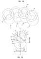
- FIG. 1Ais a top perspective view of a structural element having a plurality of notches extending from a first end.
- FIG. 1Bis a top perspective view of a curved modular implant according to one embodiment of the invention.
- FIG. 2Ais a top perspective view of a structural element having a plurality of notches extending from a first end.
- FIG. 2Bis a top perspective view of a curved modular implant according to another embodiment of the invention.
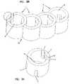
- FIG. 3Ais a top perspective view of a structural element having a plurality of notches extending from a first and second end.
- FIG. 3Bis a top perspective view of a curved modular implant according to another embodiment of the invention.
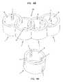
- FIG. 4Ais a top perspective view of a structural element having a plurality of notches extending from a first and second end.
- FIG. 4Bis a top perspective view of a curved modular implant according to another embodiment of the invention.
- FIG. 5is a schematic top view of a modular implant according to one embodiment of the invention.
- FIG. 6is a schematic top view of a modular implant including one or more inserts.
- FIG. 7is a side elevational view of an insert according to the invention.
- FIG. 8is a schematic top view of a modular implant in a clustered configuration.
- FIG. 9is a schematic top view of a modular implant in a curved configuration.
- FIG. 10is a schematic top view of a modular implant in a linear configuration.
- FIG. 11is a schematic side elevational view of a modular implant with structural elements of varying heights to approximate a lordotic angle.
- FIG. 12is a schematic side elevational view of a modular implant including structural elements with non-parallel end surfaces to approximate a lordotic angle.
- FIG. 13is a schematic top view of an alternative structural element.
- FIG. 14is a side elevational view of an alternative structural element.
- FIG. 15is a schematic top view of an alternative modular implant with structural elements having differing shapes in cross section.
- FIG. 16is a schematic top view of an alternative modular implant with structural elements having differing shapes in cross section.
- FIG. 17Ais a schematic top view of a structural element having a shape of a triangulated cylinder in cross section.
- FIG. 17Bis a schematic top view of an alternative modular implant with triangulated cylindrical structural elements in a curved configuration.
- FIG. 17Cis a schematic top view of an alternative modular implant with triangulated cylindrical structural elements in a linear configuration.
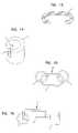
- FIG. 18is a photograph showing the location from which cylinders for constructing structural elements may be obtained from human cadaveric tibia.
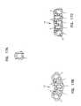
- FIG. 19is a photograph with a schematic overlay showing the location from which cylinders for constructing structural elements may be obtained from human cadaveric tibia.
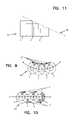
- FIG. 20is a top perspective view of an inserter tool.
- FIG. 21is a close-up of the jaws of the inserter tool of FIG. 21 .
- FIG. 22is a side elevational view of an inserter tool engaging a structural element.
- FIG. 23is a perspective view of the inserter tool of FIG. 23 , shown from the rear.
- FIG. 24is a close-up of the jaws of an inserter tool engaging a structural element.
- the inventionprovides a modular implant for fusing one or more bones.
- the modular implantcan be used to restore intravertebral disc height and stabilize the vertebral column, while allowing intervertebral (interbody) fusion to occur at the implanted spinal level.
- intervertebralinterbody
- the inventionis not so limited.
- the inventioncan be used to fuse other bones, including but not limited to, fractures of or separations in a femur, tibia, humerus, or other long bone.
- the implantsare suitable for use with or without additional supporting devices, such as rods, screws, hooks, plates and the like.
- the modular implantis formed from two or more structural elements that can be assembled, pre-implantation, in a variety of shapes and sizes to accommodate varying patient anatomies and surgical procedures.
- the structural elementmay be assembled during implantation.
- the structural elementscan be assembled to form modular implants having various sizes and shapes (e.g., curved, straight, clustered, lordotic, etc.).
- the modular implantcan be implanted in a minimally invasive fashion, from either a posterior, anterior, or lateral approach.
- the modular nature of the implantallows for the use of structural elements having an aspect ratio greater than 1.
- an object having an aspect ratio greater than 1tends to be “unstable” and prone to tipping over.
- two or more such structural elementsare coupled together, to form an implant with an aspect ratio of less than or equal to 1.
- the allowable dimensionspermit structural elements to be constructed from a previously underutilized source of cadaveric bone, for example, the human tibia.
- the designadvantageously does not require the use of a connector or protrusion to engage the structural elements.
- the designeliminates the need for a connector or protrusion, which may create a locus of weakness, enlarge the overall profile of the modular implant, and/or complicate the assembly of the modular implant.
- FIG. 1AOne embodiment of a structural element is shown in FIG. 1A .
- the structural element 1includes a first end 2 and a second end 3 spaced apart by an axis A—A of the structural element 1 .
- a side surface 4extends between the first end 2 and the second end 3 .
- the side surface 4 of each structural elementincludes one or more recesses 7 that are configured to matingly engage one or more recesses 7 of another structural element 1 (see FIG. 1B ).
- the first 2 and second ends 3are each load-bearing surfaces that contact the surface of the bone to be fused.
- the first end 2contacts the inferior endplate of a first vertebrae and the second end 3 contacts the superior endplate of the second vertebrae (i.e., the load-bearing surface is the bone-contacting surface).
- the first 2 and second 3 end surfacesare substantially parallel (i.e., with one or both end surfaces converging or diverging at an angle of less than about two degrees, more typically less than about one degree), see, for example, FIG. 11 .
- first 2 and second 3 end surfacesmay be non-parallel (i.e., with one or both surfaces converging or diverging), see, for example, FIG. 12 .
- the first 2 and second 3 end surfacesconverge to approximate a lordotic angle ⁇ .
- the end surfaces 2 , 3converge at an angle between about 0 degrees and about 12 degrees, more typically at an angle between about 2 degrees and about 5 degrees, most typically, at an angle between about 2 degrees and about 3 degrees.
- the first 2 and/or second 3 end surfacescan be textured to improve frictional engagement with the bone surface of the patient. Examples of textured surfaces include, but are not limited to, grooves, ridges, knurls, teeth, cross-cuts, serrations, and the like.
- the structural elementincludes a lumen or void.
- the structural elementmay include an opening 5 in either the first or second end 2 , 3 , or both. If desired, the opening 5 in one or more structural elements 1 can extend from the first end 2 to the second end 3 of the structural element 1 .
- Each opening 5has an inner surface 6 .
- the section of the structural element 1 disposed between the side surface 4 and the inner surface 6 of the opening 5can be referred to as a wall 12 . That is to say, the wall 12 may be defined by the inner surface 6 of at least one opening 5 , at least one load-bearing surface 2 , 3 , and, the side surface 4 of the structural element 1 .
- the thickness of the wall 12can be varied, typically the wall 12 has a thickness between about 1 mm and about 5 mm, more typically between about 2 mm and about 4 mm, most typically between about 2 mm and about 3 mm.
- a structural element with a thicker walli.e., between about 3 mm and about 4 mm
- a structural element with a thinner walli.e., between about 1 mm and about 2 mm
- FIGS. 2 and 4Compare, for example, FIGS. 2 and 4 .
- one or more recesses 7extend from the side surface 4 of the structural element 1 to the inner surface 6 of the opening 5 in the structural element 1 .
- the recesses 7each have an inner surface 13 .
- the recesses 7extend from the first 2 or second 3 end, or both, in a direction parallel to the axis A—A of the structural element 1 .
- Recesses 7 that extend from the first 2 or second 3 end (or both)also can be referred to as notches.
- the portion of the wall 12 of the structural element 1 located between two recesses 7can be referred to as a column C.
- the walls of inner surface 13 of the recess 7are substantially parallel. In an alternative embodiment, the walls of the inner surface 13 of the recess are converging to improve the strength/tightness of fit between the coupled structural elements 1 .
- the structural element 1may be desirable to form a structural element 1 having a plurality of evenly spaced recesses 7 .
- the plurality of recesses 7are evenly spaced around the perimeter (p).
- the recesses 7are not evenly spaced around the perimeter (p).
- the recesses 7are configured as notches that are not evenly spaced around the perimeter (p) of the structural element 1 .
- the structural element 1includes recesses 7 that define at least one minor column C′.
- the term “minor column” C′refers to a column whose radial arc is smaller than that of at least one other column C of the structural element 1 . For example, in the embodiment shown in FIG.
- the structural element 1includes four recesses 7 that extend from a first end 2 to define four columns C.
- the recesses 7are spaced such that they define at least one minor column C′.
- the minor column C′is smaller than the other columns C.
- the notches 7can all extend from one side surface, as shown in FIGS. 1A and 2A , or the notches 7 can extend from both side surfaces, as shown in FIGS. 3A and 4A .
- the modular implant 20may include one or more “end” structural elements 1 that include recesses 7 that do not mate with recesses 7 of another structural element 1 (see, for example, FIGS. 2B , 3 B and 4 B).
- specialized “end” structural elements 1can be provided, such that the resulting modular implant 20 does not include an “end” structural element with “unmated” recesses 7 (see, for example, FIG. 1B )
- suitable textured surfacesinclude grooves, knurls, etc.
- Specifically oriented patternscan be designed to enhance “locking” between structural elements 1 .
- the structural element 1can have any suitable shape (see, for example, FIGS. 1–18 ).
- at least one structural elementhas a substantially round shape in cross-section, for example, the structural element 1 may be circular, oval, or elliptical in cross-section.
- the term “rounded”refers to a structural element 1 with at least one arcuate surface. Therefore, the term “rounded” also includes structural elements 1 that have the shape of a “truncated circle” (or “truncated cylinder”) in cross section.
- truncated circlerefers to a shape formed by cutting one or more flat surfaces into the circumference of a circle.
- a “truncated circle”can be a shape formed by cutting a circle in half, to form a semi-circle.
- a “truncated circle”is a “triangulated circle.”
- the term “triangulated circle”refers to a shape that is created by cutting three flat surfaces of a circle.
- a “triangulated circle”has a shape of a triangle, but the angles (or corners) are rounded.
- the structural elementhas a shape in cross-section that is angled, for example, the structural element 1 may be square, triangular, rectangular, trapezoidal, or a rhombus in cross section.
- the term “angled”refers to a shape formed by the intersection of two planes. Included within the scope of this invention are structural elements having a shape that is both “rounded” and “angled” in cross section.
- the structural element 1is substantially in the shape of a cylinder (see, for example, FIGS. 1–4 ). In another embodiment, the structural element 1 is in the shape of a triangulated cylinder (see, for example, FIGS. 17A–C ).
- the structural element 1can be any size suitable for the site of implantation.
- a structural element 1can have a major width ranging between about 7 mm to about 28 mm and a height between about 5 mm to about 20 mm.
- the size of the structural element 1also may vary depending on the desired surgical procedure and patient anatomy.
- a structural element 1 for use in constructing a modular implant 20 for fusing cervical vertebrae of an adult human patientwill have a major width between about 5 mm to about 10 mm and a height between about 5 mm to about 9 mm.
- a structural element 1 for use in constructing a modular implant 20 for fusing lumbar vertebrae of an adult human patientwill generally have a major width between about 7 mm to about 28 mm and a height between about 8 mm to about 20 mm.
- the “major width” of a structural element 1can be determined by calculating the length of a vector (V) extending in a direction perpendicular from a first point on the perimeter (p) of the side surface of the structural element to a second point on the perimeter (p) of the side surface.
- the length of the vector (V) having the longest lengthis the “major width” of the structural element 1 .
- the “major width”corresponds to the outer diameter (OD) of the cylinder.
- the “major width”can be determined as described above.
- the “height” of a structural element 1can be determined by measuring the distance between the first 2 and second 3 end surfaces. If the first 2 and second 3 end surfaces are not parallel, the greatest distance therebetween is used to assess the “height” of the structural element 1 .
- the structural element 1can be constructed from any suitable biocompatible material, such as bone, metal, ceramic, plastic, and combinations thereof.
- suitable bone materialsinclude materials from human (including both allograft and autograft) and animal sources (e.g., xenograft, for example, bovine sources), typically from long bones such as the tibia, femur, and humerus.
- Suitable plasticsinclude polyetheretherketone (PEEK). The plastic can be used with or without carbon fiber (i.e., to enhance structural strength).
- Suitable metalsinclude titanium and titanium alloys (such as Ti 6AI 4V), memory metals such as NitinolTM, stainless steels (such as 306L) and porous metals.
- the structural elementcan be constructed from an osteoinductive material, osteoconductive material, radio opaque material, radiolucent material, and combinations thereof.
- the structural element 1is constructed from a bone material, for example, from a tibial source (such as a human tibial source, typically, a human cadaveric source).
- a tibial sourcesuch as a human tibial source, typically, a human cadaveric source.
- the tibiais the second largest bone of the human skeleton, it is generally not used in fusion implants due to the limited dimensions of cortical bone that can be harvested.
- an expanded range of sources of cortical bonesuch as the tibia, now can be used.
- FIG. 18shows a possible location from which cortical bone can be harvested from a human tibia (T).
- the shaft of the tibiais approximately triangular in transverse section with medial (M), lateral (L) and posterior (P) surfaces formed from cortical bone.
- medial (M) and lateral (L) surfacesintersect to define a medullary cavity.
- the medial (M) and lateral (L) surfacesintersect at an anterior (A) junction, which generally has a greater dimension than the medial (M), lateral (L) and posterior (P) surfaces.
- Aanterior
- cylinders of cortical boneare machined from the anterior (A) junction of the tibia.
- “triangulated” cylinderscan be machined from the anterior (A) junction, as shown in FIG. 19 . It may be desirable to machine “triangulated” cylinders as certain segments of a long bone (e.g., a tibia) have an anterior junction of insufficient dimensions to provide a completely round structural element. Triangulated cylinders offer the advantage of a larger cooperative opening and alternative final implant geometries when coupled together.
- the structural element 1when the structural element 1 is constructed from bone material obtained from a tibial source, the structural element has a major width of less than about 11 mm.
- a structural element 1 harvested from a human tibiawill have a major width between about 8 mm and about 11 mm, more typically between about 8 mm and about 10 mm, most typically between about 8 mm and about 9 mm, particularly if the bone is harvested from the anterior junction of the tibia.
- the inventionalso provides a modular implant 20 constructed by coupling two or more of the structural elements 1 , described above.
- the structural elements 1can be coupled, prior to implantation, to form a “customized” modular implant 20 designed for the anatomy of a particular patient and/or a particular surgical procedure.
- Modular implants 20 having a variety of shapes and sizescan be constructed, depending on the number, orientation and assembly of the structural elements 1 .
- the modular implantincludes between 2 and 10 structural elements 1 that are coupled together.
- Modular implants 20 having varying heightsalso can be created, using structural elements 1 having different heights.
- a modular implant 20 suitable for use in fusing lumbar vertebraemay be assembled using structural elements 1 having a height between about 8 mm and about 20 mm.
- a modular implant 20 suitable for use in fusing cervical vertebraemay be assembled using structural elements 1 having a height between about 5 mm and about 9 mm.
- a “stepped” modular implant 20also can be created for maintaining a lordotic angle by assembling two or more structural elements 1 of varying heights (see, for example, FIG. 11 ). If desired, a “lordotic” modular implant 20 can be assembled using structural elements 1 having first 2 and second 3 end surfaces that are angled with respect to each other (see, for example, FIG. 12 ). Tn one embodiment, a modular implant 20 includes at least one structural element 1 that has a height that is different than the height of at least one other structural element 1 . In another embodiment, a plurality of structural elements 1 having various heights are coupled to form a modular implant.
- one or more structural elements 1 constructed from different materialscan be combined in a single modular implant 20 .
- metal and bone structural elements 1can be coupled to create a modular implant 20 having the enhanced strength characteristics of metal and the biological advantages of bone (e.g., creeping substitution, osteoconductivity, etc.).
- at least one structural element 1is constructed from a material that is different than at least one other structural element 1 .
- One or more structural elements 1 having differing shapes in cross-sectionalso can be coupled together to form a modular implant 20 (see, for example, FIGS. 15 and 16 ).
- at least one structural elementhas a shape in cross-section that is different from at least one other structural element.
- one or more recesses 7extend from the side surface 4 of the structural element to the inner surface 6 of the opening 5 in the structural element.
- the recess 7has a width that corresponds to a width of the wall 12 of the structural element 1 it is configured to matingly engage.
- the recess 7 widthmay be somewhat smaller than the wall 12 width (e.g., to provide a “press-fit” coupling of the structural elements).
- the recess 7 widthmay be somewhat larger than the wall 12 width (e.g., to provide a degree of “play” and/or to accommodate the inclusion of a bonding agent or in the coupling of the structural elements).
- first 2 , second 3 , or both, end surfacescan be smooth or may include a textured pattern to enhance frictional engagement with the bone surface.
- the textured pattern of the structural elementsmay align or be unidirectional when the structural elements 1 are coupled, or the textured pattern of the various structural elements 1 may run in different directions.
- the side surfaces of the structural elementsmay function as the bone-contacting surface, and thus may include similar textured patterns.
- the structural elements 1 of the inventioncan be assembled to form modular implants 20 having various shapes.
- the structural elements 1can be assembled to form clustered, curved, and/or linear implants (see, FIGS. 8 , 9 , and 10 , respectively).
- the term “linear”refers to a modular implant 20 in which each structural element 1 is adjacent to no more than two other structural elements, and wherein a line connecting the axes A—A of the structural elements 1 (see e.g., line a′—a′ of the modular implant in FIG. 10 ) is generally linear.
- the term “curved”refers to a modular implant 20 in which each structural element 1 is adjacent to no more than two other structural elements, wherein a line connecting the axes A—A of the structural elements 1 (see e.g., line a′—a′ of the modular implant of FIG. 9 ) is curved.
- the curvaturecan be unidirectional, like the letter “C”; bi-directional, like the letter “S”; or even multi-directional (e.g., sinusoidal).
- the modular implantsmay also be assembled both into shapes including linear and curves sections (e.g., a “U” shaped modular implant).
- the radius of curvaturecan be altered by changing the location and/or orientation of the recesses 7 around the perimeter (p) of the structural element 1 .
- a curved modular implant 20will tend to have more stability in a direction transverse to the axis a′—a′ than a linear modular implant 20 .
- Suitable radii of curvatureinclude those between about 18 and about 50.
- each structural elementmay have a perimeter (p) and a plurality of recesses 7 that are not evenly spaced around the perimeter (p), such that the recesses 7 define at least one minor column C′, which is smaller than the other columns.
- the minor column C′is aligned towards the inside of the curve.
- the minor column C′is placed on alternating sides of the implant. (See, FIGS. 9 and 10 , respectively).
- the length of a modular implant 20 resulting from assembly of a specified number of structural elements 1can be varied by altering the spacing between the recesses.
- a curved implant constructed from five structural elements 1each having an outer diameter (OD) of 8 mm can have a length (X) of 22 mm.
- the curved implantcan have a length (X) of 28 mm. (See, FIG. 5 ).
- the modular implants 20 of the inventiontend to be stable, even when the structural elements 1 may be unstable (e.g., prone to tipping). That is because, in certain embodiments, the modular implant 20 has an aspect ratio less than or equal to one. In alternative embodiments, the modular implant includes or a radius of curvature that improves stability, even when individual structural elements 1 having an aspect ratio of greater than one are used.
- the structural elements 1 of the inventioncan be constructed using sources that may not otherwise be suitable, for example, tibial bone material (see discussion above) and/or be used in a wider array of indications (e.g., cervical and lumbar fusion procedures) than previously known.
- the term “aspect ratio” of a structural elementrefers to the ratio of the height of a structural element to the width of at least one load-bearing surface of the structural element.
- the width of a structural element having a circular cross sectioncan be determined by calculating the diameter of the circle.
- the width the of the load-bearing surfacecan be calculated by calculating the length of a vector extending in a direction perpendicular from a first point on the perimeter of the load-bearing surface to a second point on the perimeter of the load-bearing surface.
- the modular implant 20includes at least one structural element 1 that has an aspect ratio that is different than the aspect ratio of at least one other structural element 1 .
- at least one structural element 1has an aspect ratio of greater than one, wherein the modular implant 20 has an aspect ratio that is less than or equal to one.
- the structural elements 1when the structural elements 1 are coupled together to form a modular implant 20 , the structural elements are in an “overlapping” configuration.
- the term “overlapping”means that a width of the modular implant is less than the sum of the width of the structural elements 1 .
- both the first 2 and second 3 end surfaces of each structural element 1remain bone-contacting surfaces, even when the structural elements are interlocked.
- the axes of the structural elements 1are parallel.
- the inner surface 6 of at least one structural element 1faces the inner surface 6 of at least one another structural element 1 .
- a biocompatible bonding agentcan be used to secure the coupling of the structural elements 1 , if desired.
- suitable biocompatible bonding agentsinclude polymethylmethacrylate (PMMA), and fibrin glue.
- the modular implant 20can be hydrated (for example, by immersing the implant 20 in a saline solution at a temperature between about 18° C. and about 25° C., for between about 30 minutes and about 45 minutes) to cause the coupled structural elements 20 to swell and increase the mechanical locking force between them. Hydration is particularly suitable when the modular implant 20 is assembled from structural elements 1 constructed from a hydratable material, for example, a bone material.
- the modular implant 20includes a biologically active agent, such as a bone growth enhancing material or an antibiotic.
- a biologically active agentrefers to, without limitation, physiologically or pharmacologically active substances that act locally or systemically in the body. Of particular suitability for this invention are biologically active agents that are osteoinductive or osteoconductive.
- materials that enhance bone growth and/or fusioninclude, but are not limited to, bone or bone substitute products such as human growth factors, bone morphogeneic proteins (BMP), cancellous bone, autograft bone, allograft bone, etc.
- antibioticsinclude antimicrobials and antibacterials.
- one or more structural elements 1may include a lumen or void.
- the structural elementmay include at least one opening 5 in at least end surface 2 , 3 , wherein each opening 5 has an inner surface 6 .
- the biologically active agentcan be placed within the void or opening 5 .
- the implant 20includes one or more cooperative openings 9 defined by the inner surface 6 of an opening 5 in a first structural element 1 and a side surface 4 of an overlapping structural element 1 .
- one or more inserts 11can be configured to be received within a cooperative opening 9 of the implant 20 (see, for example, FIGS. 6 and 7 ).
- the insert 11can be constructed from any suitable material.
- the insert 11includes a biologically active agent. As shown in FIGS. 17B–C , structural elements 1 formed as a “triangulated cylinder” tend to increase the size of the cooperative opening 9 in the modular implant 20 .
- the inventionalso includes a method for fusing one or more bones.
- the methodincludes obtaining or providing two or more structural elements 1 , described above.
- the recesses of the structural elements 1are engaged to form a modular implant 20 , which is then inserted between the bones to provide stability and/or enhance fusion.
- the structural elementsmay be engaged during and/or at the site of implantation.
- the implant 20 of the inventionis used to facilitate fusion of adjacent vertebrae, including cervical, thoracic, and lumbar vertebrae.
- the assembled implant 20can be inserted into the disc space via an anterior approach, posterior, or lateral approach.
- anterior approachposterior, or lateral approach.
- Those of skill in the artare familiar with methods for implanting spinal fusion devices from these approaches, including open, and minimally invasive, for example, laproscopic procedures.
- when used in connection with a posterior approachit may be desirable to assemble the structural elements 1 to form a curved or linear implant 20 .
- the medical practitionercan assemble the structural elements 1 to form a modular implant 20 suitable for the particular anatomy of the patient or surgical procedure used.
- the inventionalso includes an inserter tool 50 useful for handling and/or implanting the modular implant 20 , described above.
- the inserter tool 50includes a pair of intersecting arms and a common axis interconnecting the intersecting arms wherein the arms are capable of rotating around the common axis ( FIG. 20 ).
- the inserter tool 50includes first 51 and second 52 arms.
- the first arm 51includes a first proximal shaft 53 and a first distal shaft 54 .
- a first moveable head 55is rotatably connected to the first distal shaft 54 at a first axis 56 .
- the second arm 52includes a second proximal shaft 57 and a second distal shaft 58 .
- a second moveable head 59is rotatably connected to the second distal shaft 58 at a second axis 60 and connected to the first movable head 55 at a third axis 61 .
- the first 51 and second 52 armsare pivotally connected at a fourth axis 62 and are capable of rotating around the fourth axis 62 .
- the inserter toolcan include a biasing member configured to hold the first proximal shaft 53 and second proximal shaft 57 in a spaced apart relationship.
- the inserter tool 50also may include a base member 63 attached to the first 51 and second 52 arms at the third 61 and fourth 62 axes.
- the first 55 and second 59 moveable headsspan a width (W) when engaging the modular implant 20 .
- the “width” spanned by the first moveable head 55 and second moveable head 59refers to the distance between the first exterior surface 66 of the first moveable head 55 and the second exterior surface 67 of the second moveable head 59 .
- the width (W) spanned by the first 55 and second 59 moveable heads when engaging the modular implant 20is no greater than a major width of at least one structural element 1 of the implant 20 .
- the clampcan be constructed using any suitable material, including metal, such as stainless steel or titanium or plastics such as injection-molded plastic.
- the arms 51 , 52 of the inserter tool 50are rotated apart and a modular implant 20 is positioned between the first 55 and second 59 moveable head.
- the arms 51 , 52 of the inserter tool 50are then rotated towards one another to engage the modular implant 20 .
- the first moveable head 55includes a first projection 64 configured to engage a first recess 7 of the modular implant 20 .
- the second moveable head 59includes a second projection 65 configured to engage a second recess 7 of the modular implant 20 ( FIGS. 22–24 ).
- the first 55 and second 59 moveable headsare configured to frictionally engage the side surface 4 of at least one structural element 1 of the modular implant 20 .
Landscapes
- Health & Medical Sciences (AREA)
- Engineering & Computer Science (AREA)
- Biomedical Technology (AREA)
- Orthopedic Medicine & Surgery (AREA)
- Transplantation (AREA)
- Neurology (AREA)
- Heart & Thoracic Surgery (AREA)
- Oral & Maxillofacial Surgery (AREA)
- Cardiology (AREA)
- Vascular Medicine (AREA)
- Life Sciences & Earth Sciences (AREA)
- Animal Behavior & Ethology (AREA)
- General Health & Medical Sciences (AREA)
- Public Health (AREA)
- Veterinary Medicine (AREA)
- Physical Education & Sports Medicine (AREA)
- Prostheses (AREA)
- Spinning Methods And Devices For Manufacturing Artificial Fibers (AREA)
Abstract
Description
Claims (26)
Priority Applications (1)
| Application Number | Priority Date | Filing Date | Title |
|---|---|---|---|
| US10/261,081US7037339B2 (en) | 2001-09-27 | 2002-09-27 | Modular spinal fusion device |
Applications Claiming Priority (2)
| Application Number | Priority Date | Filing Date | Title |
|---|---|---|---|
| US32558501P | 2001-09-27 | 2001-09-27 | |
| US10/261,081US7037339B2 (en) | 2001-09-27 | 2002-09-27 | Modular spinal fusion device |
Publications (2)
| Publication Number | Publication Date |
|---|---|
| US20030078661A1 US20030078661A1 (en) | 2003-04-24 |
| US7037339B2true US7037339B2 (en) | 2006-05-02 |
Family
ID=23268491
Family Applications (1)
| Application Number | Title | Priority Date | Filing Date |
|---|---|---|---|
| US10/261,081Expired - LifetimeUS7037339B2 (en) | 2001-09-27 | 2002-09-27 | Modular spinal fusion device |
Country Status (9)
| Country | Link |
|---|---|
| US (1) | US7037339B2 (en) |
| EP (1) | EP1429693B1 (en) |
| JP (1) | JP2005503866A (en) |
| AT (1) | ATE314828T1 (en) |
| AU (1) | AU2002330148B2 (en) |
| CA (1) | CA2461235A1 (en) |
| DE (1) | DE60208569T2 (en) |
| ES (1) | ES2257569T3 (en) |
| WO (1) | WO2003026538A1 (en) |
Cited By (73)
| Publication number | Priority date | Publication date | Assignee | Title |
|---|---|---|---|---|
| US20050038517A1 (en)* | 2003-08-13 | 2005-02-17 | Carrison Harold F. | Apparatus and methods of reducing bone compression fractures using wedges |
| US20060106462A1 (en)* | 2002-04-16 | 2006-05-18 | Tsou Paul M | Implant material for minimally invasive spinal interbody fusion surgery |
| US20060189999A1 (en)* | 2005-02-24 | 2006-08-24 | Paul Zwirkoski | Linked slideable and interlockable rotatable components |
| US20070093898A1 (en)* | 2005-09-26 | 2007-04-26 | Schwab Frank J | Transforaminal hybrid implant |
| US20080206297A1 (en)* | 2007-02-28 | 2008-08-28 | Roeder Ryan K | Porous composite biomaterials and related methods |
| US20090099661A1 (en)* | 2007-08-14 | 2009-04-16 | Jinia Bhattacharya | Multiple component osteoimplant |
| US20110178465A1 (en)* | 2008-10-15 | 2011-07-21 | Bioshape Solutions Inc | Device and method for delivery of therapeutic agents via internal implants |
| US20110184515A1 (en)* | 2004-08-11 | 2011-07-28 | Nonliner Technologies Ltd. | Devices For Introduction Into A Body Via A Substantially Straight Conduit To Form A Predefined Curved Configuration, And Methods Employing Such Devices |
| US8043380B1 (en)* | 2003-07-31 | 2011-10-25 | Aesculap Implant Systems, Llc. | Bone implant with osteo-inducing structure |
| US20120158150A1 (en)* | 2004-08-11 | 2012-06-21 | Tzony Siegal | Devices for introduction into a body via a substantially straight conduit to form a predefined curved configuration, and methods employing such devices |
| USRE43714E1 (en) | 1999-12-15 | 2012-10-02 | Zimmer Orthobiologics, Inc. | Preparation for repairing cartilage defects or cartilage/bone defects in human or animal joints |
| US20120265306A1 (en)* | 2011-04-14 | 2012-10-18 | Warsaw Orthopedic, Inc. | Spinal implant with attachable bone securing componet |
| US8753406B2 (en) | 2010-08-31 | 2014-06-17 | Zimmer Inc. | Osteochondral graft delivery device and uses thereof |
| US8828082B2 (en) | 2009-07-09 | 2014-09-09 | R Tree Innovations, Llc | Inter-body implant |
| US9044333B2 (en) | 2007-07-27 | 2015-06-02 | R Tree Innovations, Llc | Inter-body implantation system and method |
| US9198765B1 (en) | 2011-10-31 | 2015-12-01 | Nuvasive, Inc. | Expandable spinal fusion implants and related methods |
| US9295562B2 (en) | 2008-01-17 | 2016-03-29 | DePuy Synthes Products, Inc. | Expandable intervertebral implant and associated method of manufacturing the same |
| US9320615B2 (en) | 2010-06-29 | 2016-04-26 | DePuy Synthes Products, Inc. | Distractible intervertebral implant |
| US9320617B2 (en) | 2012-10-22 | 2016-04-26 | Cogent Spine, LLC | Devices and methods for spinal stabilization and instrumentation |
| US9402737B2 (en) | 2007-06-26 | 2016-08-02 | DePuy Synthes Products, Inc. | Highly lordosed fusion cage |
| US9414934B2 (en) | 2008-04-05 | 2016-08-16 | DePuy Synthes Products, Inc. | Expandable intervertebral implant |
| US9445918B1 (en) | 2012-10-22 | 2016-09-20 | Nuvasive, Inc. | Expandable spinal fusion implants and related instruments and methods |
| US9526620B2 (en) | 2009-03-30 | 2016-12-27 | DePuy Synthes Products, Inc. | Zero profile spinal fusion cage |
| US9561117B2 (en) | 2012-07-26 | 2017-02-07 | DePuy Synthes Products, Inc. | Expandable implant |
| US9700425B1 (en) | 2011-03-20 | 2017-07-11 | Nuvasive, Inc. | Vertebral body replacement and insertion methods |
| US9717601B2 (en) | 2013-02-28 | 2017-08-01 | DePuy Synthes Products, Inc. | Expandable intervertebral implant, system, kit and method |
| US9724207B2 (en) | 2003-02-14 | 2017-08-08 | DePuy Synthes Products, Inc. | In-situ formed intervertebral fusion device and method |
| US9750552B2 (en) | 2009-07-06 | 2017-09-05 | DePuy Synthes Products, Inc. | Expandable fixation assemblies |
| US9757248B2 (en) | 2014-04-08 | 2017-09-12 | Degen Medical, Inc. | Intervertebral spacers |
| US9833334B2 (en) | 2010-06-24 | 2017-12-05 | DePuy Synthes Products, Inc. | Enhanced cage insertion assembly |
| US9867714B1 (en) | 2011-09-23 | 2018-01-16 | Samy Abdou | Spinal fixation devices and methods of use |
| US20180028331A1 (en)* | 2006-11-21 | 2018-02-01 | Vertebral Technologies, Inc. | Methods and apparatus for minimally invasive modular interbody fusion devices |
| US9913727B2 (en) | 2015-07-02 | 2018-03-13 | Medos International Sarl | Expandable implant |
| US9949769B2 (en) | 2004-03-06 | 2018-04-24 | DePuy Synthes Products, Inc. | Dynamized interspinal implant |
| US9993349B2 (en) | 2002-06-27 | 2018-06-12 | DePuy Synthes Products, Inc. | Intervertebral disc |
| US10159582B2 (en) | 2011-09-16 | 2018-12-25 | DePuy Synthes Products, Inc. | Removable, bone-securing cover plate for intervertebral fusion cage |
| US20190000628A1 (en)* | 2011-02-28 | 2019-01-03 | DePuy Synthes Products, Inc. | Modular tissue scaffolds |
| US10258483B2 (en) | 2016-08-19 | 2019-04-16 | Degen Medical, Inc. | Laminate implantable medical devices |
| US10369015B2 (en) | 2010-09-23 | 2019-08-06 | DePuy Synthes Products, Inc. | Implant inserter having a laterally-extending dovetail engagement feature |
| US10390963B2 (en) | 2006-12-07 | 2019-08-27 | DePuy Synthes Products, Inc. | Intervertebral implant |
| US10398563B2 (en) | 2017-05-08 | 2019-09-03 | Medos International Sarl | Expandable cage |
| US10433974B2 (en) | 2003-06-30 | 2019-10-08 | DePuy Synthes Products, Inc. | Intervertebral implant with conformable endplate |
| US10500062B2 (en) | 2009-12-10 | 2019-12-10 | DePuy Synthes Products, Inc. | Bellows-like expandable interbody fusion cage |
| US10537436B2 (en) | 2016-11-01 | 2020-01-21 | DePuy Synthes Products, Inc. | Curved expandable cage |
| US10543107B2 (en) | 2009-12-07 | 2020-01-28 | Samy Abdou | Devices and methods for minimally invasive spinal stabilization and instrumentation |
| US10548740B1 (en) | 2016-10-25 | 2020-02-04 | Samy Abdou | Devices and methods for vertebral bone realignment |
| US10695105B2 (en) | 2012-08-28 | 2020-06-30 | Samy Abdou | Spinal fixation devices and methods of use |
| US10736752B1 (en) | 2017-10-24 | 2020-08-11 | Omnia Medical, LLC | Multi-material multi-component spinal implant |
| US10857003B1 (en) | 2015-10-14 | 2020-12-08 | Samy Abdou | Devices and methods for vertebral stabilization |
| US10888433B2 (en) | 2016-12-14 | 2021-01-12 | DePuy Synthes Products, Inc. | Intervertebral implant inserter and related methods |
| US10918498B2 (en) | 2004-11-24 | 2021-02-16 | Samy Abdou | Devices and methods for inter-vertebral orthopedic device placement |
| US10940016B2 (en) | 2017-07-05 | 2021-03-09 | Medos International Sarl | Expandable intervertebral fusion cage |
| US10973648B1 (en) | 2016-10-25 | 2021-04-13 | Samy Abdou | Devices and methods for vertebral bone realignment |
| US11006982B2 (en) | 2012-02-22 | 2021-05-18 | Samy Abdou | Spinous process fixation devices and methods of use |
| US11123198B2 (en) | 2018-11-13 | 2021-09-21 | Degen Medical, Inc. | Expandable spacers |
| US11179248B2 (en) | 2018-10-02 | 2021-11-23 | Samy Abdou | Devices and methods for spinal implantation |
| US11234829B2 (en) | 2019-01-21 | 2022-02-01 | Degen Medical, Inc. | Expandable intervertebral spacers |
| US11344424B2 (en) | 2017-06-14 | 2022-05-31 | Medos International Sarl | Expandable intervertebral implant and related methods |
| US11426290B2 (en) | 2015-03-06 | 2022-08-30 | DePuy Synthes Products, Inc. | Expandable intervertebral implant, system, kit and method |
| US11426286B2 (en) | 2020-03-06 | 2022-08-30 | Eit Emerging Implant Technologies Gmbh | Expandable intervertebral implant |
| US11446156B2 (en) | 2018-10-25 | 2022-09-20 | Medos International Sarl | Expandable intervertebral implant, inserter instrument, and related methods |
| US11452607B2 (en) | 2010-10-11 | 2022-09-27 | DePuy Synthes Products, Inc. | Expandable interspinous process spacer implant |
| US11497619B2 (en) | 2013-03-07 | 2022-11-15 | DePuy Synthes Products, Inc. | Intervertebral implant |
| US11510788B2 (en) | 2016-06-28 | 2022-11-29 | Eit Emerging Implant Technologies Gmbh | Expandable, angularly adjustable intervertebral cages |
| US11547575B2 (en) | 2019-09-27 | 2023-01-10 | Degen Medical, Inc. | Expandable intervertebral spacers |
| US11596522B2 (en) | 2016-06-28 | 2023-03-07 | Eit Emerging Implant Technologies Gmbh | Expandable and angularly adjustable intervertebral cages with articulating joint |
| US11752009B2 (en) | 2021-04-06 | 2023-09-12 | Medos International Sarl | Expandable intervertebral fusion cage |
| US11766339B1 (en) | 2017-10-24 | 2023-09-26 | Omnia Medical, LLC | Multi-material multi-component spinal implant |
| US11801144B2 (en) | 2017-09-14 | 2023-10-31 | Degen Medical, Inc. | Methods of making medical devices |
| US11850160B2 (en) | 2021-03-26 | 2023-12-26 | Medos International Sarl | Expandable lordotic intervertebral fusion cage |
| US11911287B2 (en) | 2010-06-24 | 2024-02-27 | DePuy Synthes Products, Inc. | Lateral spondylolisthesis reduction cage |
| US12090064B2 (en) | 2022-03-01 | 2024-09-17 | Medos International Sarl | Stabilization members for expandable intervertebral implants, and related systems and methods |
| US12440346B2 (en) | 2023-03-31 | 2025-10-14 | DePuy Synthes Products, Inc. | Expandable intervertebral implant |
Families Citing this family (15)
| Publication number | Priority date | Publication date | Assignee | Title |
|---|---|---|---|---|
| US20050065613A1 (en)* | 2003-09-24 | 2005-03-24 | Gross Jeffrey M. | Reinforced fusion implant |
| US20050065607A1 (en)* | 2003-09-24 | 2005-03-24 | Gross Jeffrey M. | Assembled fusion implant |
| WO2005063151A1 (en)* | 2003-12-31 | 2005-07-14 | Osteotech Inc. | Hybrid surgical implants |
| US8002840B2 (en) | 2004-01-12 | 2011-08-23 | Depuy Products, Inc. | Systems and methods for compartmental replacement in a knee |
| US8535383B2 (en)* | 2004-01-12 | 2013-09-17 | DePuy Synthes Products, LLC | Systems and methods for compartmental replacement in a knee |
| JP4510030B2 (en)* | 2004-01-12 | 2010-07-21 | デピュイ・プロダクツ・インコーポレイテッド | System and method for splitting and replacing a knee |
| US7544208B1 (en) | 2004-05-03 | 2009-06-09 | Theken Spine, Llc | Adjustable corpectomy apparatus |
| US8721722B2 (en)* | 2004-10-18 | 2014-05-13 | Ebi, Llc | Intervertebral implant and associated method |
| US7618457B2 (en)* | 2005-08-10 | 2009-11-17 | Zimmer Spine, Inc. | Devices and methods for disc nucleus replacement |
| US20070074980A1 (en)* | 2005-09-02 | 2007-04-05 | Bankoski Brian R | Implant rehydration packages and methods of use |
| DE102005061932A1 (en)* | 2005-12-23 | 2007-07-05 | Biedermann Motech Gmbh | Placeholder for implantation to the human vertebrae has three tubular bodies having different lengths and diameters that are inserted and connected to each other by pins so that they project over the edges of the next larger tubular body |
| US8034081B2 (en) | 2007-02-06 | 2011-10-11 | CollabComl, LLC | Interspinous dynamic stabilization implant and method of implanting |
| US9247973B2 (en) | 2007-09-28 | 2016-02-02 | DePuy Synthes Products, Inc. | Anti-microbial implant |
| WO2011098634A1 (en)* | 2010-02-12 | 2011-08-18 | Alonso Abajo Antonio Magin | Device for the treatment of spine pathologies |
| EP2535021B1 (en)* | 2011-06-14 | 2015-10-14 | Biedermann Technologies GmbH & Co. KG | Intervertebral implant |
Citations (39)
| Publication number | Priority date | Publication date | Assignee | Title |
|---|---|---|---|---|
| US748603A (en)* | 1903-01-10 | 1904-01-05 | Frank B Henry | Building-block. |
| US3562988A (en)* | 1969-06-24 | 1971-02-16 | Lock Block Co Z | Building blocks, bricks, tile, panels and the like |
| US5112354A (en) | 1989-11-16 | 1992-05-12 | Northwestern University | Bone allograft material and method |
| US5192327A (en)* | 1991-03-22 | 1993-03-09 | Brantigan John W | Surgical prosthetic implant for vertebrae |
| US5298254A (en) | 1989-09-21 | 1994-03-29 | Osteotech, Inc. | Shaped, swollen demineralized bone and its use in bone repair |
| US5306302A (en) | 1990-09-10 | 1994-04-26 | Merck Patent Gesellschaft Mit Beschrankter Haftung | Implant material |
| US5514180A (en) | 1994-01-14 | 1996-05-07 | Heggeness; Michael H. | Prosthetic intervertebral devices |
| US5653621A (en)* | 1996-01-03 | 1997-08-05 | Yao; Li-Ho | Toy building block puzzle |
| US5728159A (en) | 1997-01-02 | 1998-03-17 | Musculoskeletal Transplant Foundation | Serrated bone graft |
| WO1998017209A2 (en) | 1996-10-23 | 1998-04-30 | Sdgi Holdings, Inc. | Spinal spacer |
| WO1999009914A1 (en) | 1997-08-27 | 1999-03-04 | University Of Florida Tissue Bank, Inc. | Cortical bone cervical smith-robinson fusion implant |
| US5893890A (en) | 1994-03-18 | 1999-04-13 | Perumala Corporation | Rotating, locking intervertebral disk stabilizer and applicator |
| US5899939A (en) | 1998-01-21 | 1999-05-04 | Osteotech, Inc. | Bone-derived implant for load-supporting applications |
| DE19710392C1 (en)* | 1997-03-13 | 1999-07-01 | Haehnel Michael | Slipped disc implant comprises an extensible, hinged or wound body |
| US5972368A (en) | 1997-06-11 | 1999-10-26 | Sdgi Holdings, Inc. | Bone graft composites and spacers |
| US6025538A (en) | 1998-11-20 | 2000-02-15 | Musculoskeletal Transplant Foundation | Compound bone structure fabricated from allograft tissue |
| US6033438A (en) | 1997-06-03 | 2000-03-07 | Sdgi Holdings, Inc. | Open intervertebral spacer |
| WO2000024327A2 (en) | 1998-10-28 | 2000-05-04 | Sdgi Holdings, Inc. | Interbody fusion grafts and instrumentation |
| WO2000041654A2 (en) | 1999-01-11 | 2000-07-20 | Sdgi Holdings, Inc. | Truncated open intervertebral spacers |
| US6096080A (en) | 1998-05-06 | 2000-08-01 | Cortek, Inc. | Apparatus for spinal fusion using implanted devices |
| US6159244A (en)* | 1999-07-30 | 2000-12-12 | Suddaby; Loubert | Expandable variable angle intervertebral fusion implant |
| US6159211A (en) | 1998-10-22 | 2000-12-12 | Depuy Acromed, Inc. | Stackable cage system for corpectomy/vertebrectomy |
| WO2000074608A1 (en) | 1999-06-08 | 2000-12-14 | Osteotech, Inc. | Ramp-shaped intervertebral implant |
| US6193757B1 (en) | 1998-10-29 | 2001-02-27 | Sdgi Holdings, Inc. | Expandable intervertebral spacers |
| US6224631B1 (en)* | 1998-03-20 | 2001-05-01 | Sulzer Spine-Tech Inc. | Intervertebral implant with reduced contact area and method |
| US6258125B1 (en)* | 1998-08-03 | 2001-07-10 | Synthes (U.S.A.) | Intervertebral allograft spacer |
| US6270528B1 (en) | 1998-08-06 | 2001-08-07 | Sdgi Holdings, Inc. | Composited intervertebral bone spacers |
| WO2001070137A2 (en) | 2000-03-22 | 2001-09-27 | Synthes (U.S.A) | Multipiece implants formed of bone material |
| US20010031254A1 (en) | 1998-11-13 | 2001-10-18 | Bianchi John R. | Assembled implant |
| US6364880B1 (en)* | 1994-03-28 | 2002-04-02 | Gary Karlin Michelson | Spinal implant with bone screws |
| US20020045904A1 (en)* | 1999-01-30 | 2002-04-18 | Aesculap Ag & Co. Kg | Surgical instrument for introducing intervertebral implants |
| US6387130B1 (en)* | 1999-04-16 | 2002-05-14 | Nuvasive, Inc. | Segmented linked intervertebral implant systems |
| US20020082693A1 (en)* | 2000-07-17 | 2002-06-27 | Nuvasive, Inc. | Stackable interlocking intervertebral support system |
| US6419705B1 (en)* | 1999-06-23 | 2002-07-16 | Sulzer Spine-Tech Inc. | Expandable fusion device and method |
| US20020106393A1 (en) | 2000-02-10 | 2002-08-08 | Bianchi John R. | Assembled implant, including mixed-composition segment |
| US6468311B2 (en) | 2001-01-22 | 2002-10-22 | Sdgi Holdings, Inc. | Modular interbody fusion implant |
| US6500205B1 (en)* | 2000-04-19 | 2002-12-31 | Gary K. Michelson | Expandable threaded arcuate interbody spinal fusion implant with cylindrical configuration during insertion |
| US6558424B2 (en)* | 2001-06-28 | 2003-05-06 | Depuy Acromed | Modular anatomic fusion device |
| US6824565B2 (en)* | 2000-09-08 | 2004-11-30 | Nabil L. Muhanna | System and methods for inserting a vertebral spacer |
Family Cites Families (1)
| Publication number | Priority date | Publication date | Assignee | Title |
|---|---|---|---|---|
| US6368325B1 (en)* | 1998-05-27 | 2002-04-09 | Nuvasive, Inc. | Bone blocks and methods for inserting bone blocks into intervertebral spaces |
- 2002
- 2002-09-27DEDE60208569Tpatent/DE60208569T2/ennot_activeExpired - Lifetime
- 2002-09-27ATAT02766411Tpatent/ATE314828T1/ennot_activeIP Right Cessation
- 2002-09-27ESES02766411Tpatent/ES2257569T3/ennot_activeExpired - Lifetime
- 2002-09-27CACA002461235Apatent/CA2461235A1/ennot_activeAbandoned
- 2002-09-27JPJP2003530179Apatent/JP2005503866A/enactivePending
- 2002-09-27EPEP02766411Apatent/EP1429693B1/ennot_activeExpired - Lifetime
- 2002-09-27USUS10/261,081patent/US7037339B2/ennot_activeExpired - Lifetime
- 2002-09-27WOPCT/US2002/031013patent/WO2003026538A1/enactiveIP Right Grant
- 2002-09-27AUAU2002330148Apatent/AU2002330148B2/ennot_activeCeased
Patent Citations (40)
| Publication number | Priority date | Publication date | Assignee | Title |
|---|---|---|---|---|
| US748603A (en)* | 1903-01-10 | 1904-01-05 | Frank B Henry | Building-block. |
| US3562988A (en)* | 1969-06-24 | 1971-02-16 | Lock Block Co Z | Building blocks, bricks, tile, panels and the like |
| US5298254A (en) | 1989-09-21 | 1994-03-29 | Osteotech, Inc. | Shaped, swollen demineralized bone and its use in bone repair |
| US5112354A (en) | 1989-11-16 | 1992-05-12 | Northwestern University | Bone allograft material and method |
| US5306302A (en) | 1990-09-10 | 1994-04-26 | Merck Patent Gesellschaft Mit Beschrankter Haftung | Implant material |
| US5192327A (en)* | 1991-03-22 | 1993-03-09 | Brantigan John W | Surgical prosthetic implant for vertebrae |
| US5514180A (en) | 1994-01-14 | 1996-05-07 | Heggeness; Michael H. | Prosthetic intervertebral devices |
| US5893890A (en) | 1994-03-18 | 1999-04-13 | Perumala Corporation | Rotating, locking intervertebral disk stabilizer and applicator |
| US6364880B1 (en)* | 1994-03-28 | 2002-04-02 | Gary Karlin Michelson | Spinal implant with bone screws |
| US5653621A (en)* | 1996-01-03 | 1997-08-05 | Yao; Li-Ho | Toy building block puzzle |
| WO1998017209A2 (en) | 1996-10-23 | 1998-04-30 | Sdgi Holdings, Inc. | Spinal spacer |
| US5728159A (en) | 1997-01-02 | 1998-03-17 | Musculoskeletal Transplant Foundation | Serrated bone graft |
| DE19710392C1 (en)* | 1997-03-13 | 1999-07-01 | Haehnel Michael | Slipped disc implant comprises an extensible, hinged or wound body |
| US6033438A (en) | 1997-06-03 | 2000-03-07 | Sdgi Holdings, Inc. | Open intervertebral spacer |
| US5972368A (en) | 1997-06-11 | 1999-10-26 | Sdgi Holdings, Inc. | Bone graft composites and spacers |
| WO1999009914A1 (en) | 1997-08-27 | 1999-03-04 | University Of Florida Tissue Bank, Inc. | Cortical bone cervical smith-robinson fusion implant |
| US5899939A (en) | 1998-01-21 | 1999-05-04 | Osteotech, Inc. | Bone-derived implant for load-supporting applications |
| US6224631B1 (en)* | 1998-03-20 | 2001-05-01 | Sulzer Spine-Tech Inc. | Intervertebral implant with reduced contact area and method |
| US6096080A (en) | 1998-05-06 | 2000-08-01 | Cortek, Inc. | Apparatus for spinal fusion using implanted devices |
| US6258125B1 (en)* | 1998-08-03 | 2001-07-10 | Synthes (U.S.A.) | Intervertebral allograft spacer |
| US6270528B1 (en) | 1998-08-06 | 2001-08-07 | Sdgi Holdings, Inc. | Composited intervertebral bone spacers |
| US6159211A (en) | 1998-10-22 | 2000-12-12 | Depuy Acromed, Inc. | Stackable cage system for corpectomy/vertebrectomy |
| US6174311B1 (en) | 1998-10-28 | 2001-01-16 | Sdgi Holdings, Inc. | Interbody fusion grafts and instrumentation |
| WO2000024327A2 (en) | 1998-10-28 | 2000-05-04 | Sdgi Holdings, Inc. | Interbody fusion grafts and instrumentation |
| US6193757B1 (en) | 1998-10-29 | 2001-02-27 | Sdgi Holdings, Inc. | Expandable intervertebral spacers |
| US20010031254A1 (en) | 1998-11-13 | 2001-10-18 | Bianchi John R. | Assembled implant |
| US6025538A (en) | 1998-11-20 | 2000-02-15 | Musculoskeletal Transplant Foundation | Compound bone structure fabricated from allograft tissue |
| WO2000041654A2 (en) | 1999-01-11 | 2000-07-20 | Sdgi Holdings, Inc. | Truncated open intervertebral spacers |
| US20020045904A1 (en)* | 1999-01-30 | 2002-04-18 | Aesculap Ag & Co. Kg | Surgical instrument for introducing intervertebral implants |
| US6387130B1 (en)* | 1999-04-16 | 2002-05-14 | Nuvasive, Inc. | Segmented linked intervertebral implant systems |
| WO2000074608A1 (en) | 1999-06-08 | 2000-12-14 | Osteotech, Inc. | Ramp-shaped intervertebral implant |
| US6419705B1 (en)* | 1999-06-23 | 2002-07-16 | Sulzer Spine-Tech Inc. | Expandable fusion device and method |
| US6159244A (en)* | 1999-07-30 | 2000-12-12 | Suddaby; Loubert | Expandable variable angle intervertebral fusion implant |
| US20020106393A1 (en) | 2000-02-10 | 2002-08-08 | Bianchi John R. | Assembled implant, including mixed-composition segment |
| WO2001070137A2 (en) | 2000-03-22 | 2001-09-27 | Synthes (U.S.A) | Multipiece implants formed of bone material |
| US6500205B1 (en)* | 2000-04-19 | 2002-12-31 | Gary K. Michelson | Expandable threaded arcuate interbody spinal fusion implant with cylindrical configuration during insertion |
| US20020082693A1 (en)* | 2000-07-17 | 2002-06-27 | Nuvasive, Inc. | Stackable interlocking intervertebral support system |
| US6824565B2 (en)* | 2000-09-08 | 2004-11-30 | Nabil L. Muhanna | System and methods for inserting a vertebral spacer |
| US6468311B2 (en) | 2001-01-22 | 2002-10-22 | Sdgi Holdings, Inc. | Modular interbody fusion implant |
| US6558424B2 (en)* | 2001-06-28 | 2003-05-06 | Depuy Acromed | Modular anatomic fusion device |
Cited By (207)
| Publication number | Priority date | Publication date | Assignee | Title |
|---|---|---|---|---|
| USRE43714E1 (en) | 1999-12-15 | 2012-10-02 | Zimmer Orthobiologics, Inc. | Preparation for repairing cartilage defects or cartilage/bone defects in human or animal joints |
| US20060106462A1 (en)* | 2002-04-16 | 2006-05-18 | Tsou Paul M | Implant material for minimally invasive spinal interbody fusion surgery |
| US9993349B2 (en) | 2002-06-27 | 2018-06-12 | DePuy Synthes Products, Inc. | Intervertebral disc |
| US10238500B2 (en) | 2002-06-27 | 2019-03-26 | DePuy Synthes Products, Inc. | Intervertebral disc |
| US10405986B2 (en) | 2003-02-14 | 2019-09-10 | DePuy Synthes Products, Inc. | In-situ formed intervertebral fusion device and method |
| US11432938B2 (en) | 2003-02-14 | 2022-09-06 | DePuy Synthes Products, Inc. | In-situ intervertebral fusion device and method |
| US10555817B2 (en) | 2003-02-14 | 2020-02-11 | DePuy Synthes Products, Inc. | In-situ formed intervertebral fusion device and method |
| US9808351B2 (en) | 2003-02-14 | 2017-11-07 | DePuy Synthes Products, Inc. | In-situ formed intervertebral fusion device and method |
| US9801729B2 (en) | 2003-02-14 | 2017-10-31 | DePuy Synthes Products, Inc. | In-situ formed intervertebral fusion device and method |
| US9788963B2 (en) | 2003-02-14 | 2017-10-17 | DePuy Synthes Products, Inc. | In-situ formed intervertebral fusion device and method |
| US9814590B2 (en) | 2003-02-14 | 2017-11-14 | DePuy Synthes Products, Inc. | In-situ formed intervertebral fusion device and method |
| US9724207B2 (en) | 2003-02-14 | 2017-08-08 | DePuy Synthes Products, Inc. | In-situ formed intervertebral fusion device and method |
| US10639164B2 (en) | 2003-02-14 | 2020-05-05 | DePuy Synthes Products, Inc. | In-situ formed intervertebral fusion device and method |
| US9925060B2 (en) | 2003-02-14 | 2018-03-27 | DePuy Synthes Products, Inc. | In-situ formed intervertebral fusion device and method |
| US10433971B2 (en) | 2003-02-14 | 2019-10-08 | DePuy Synthes Products, Inc. | In-situ formed intervertebral fusion device and method |
| US11207187B2 (en) | 2003-02-14 | 2021-12-28 | DePuy Synthes Products, Inc. | In-situ formed intervertebral fusion device and method |
| US10492918B2 (en) | 2003-02-14 | 2019-12-03 | DePuy Synthes Products, Inc. | In-situ formed intervertebral fusion device and method |
| US10575959B2 (en) | 2003-02-14 | 2020-03-03 | DePuy Synthes Products, Inc. | In-situ formed intervertebral fusion device and method |
| US10085843B2 (en) | 2003-02-14 | 2018-10-02 | DePuy Synthes Products, Inc. | In-situ formed intervertebral fusion device and method |
| US10583013B2 (en) | 2003-02-14 | 2020-03-10 | DePuy Synthes Products, Inc. | In-situ formed intervertebral fusion device and method |
| US11096794B2 (en) | 2003-02-14 | 2021-08-24 | DePuy Synthes Products, Inc. | In-situ formed intervertebral fusion device and method |
| US10376372B2 (en) | 2003-02-14 | 2019-08-13 | DePuy Synthes Products, Inc. | In-situ formed intervertebral fusion device and method |
| US9814589B2 (en) | 2003-02-14 | 2017-11-14 | DePuy Synthes Products, Inc. | In-situ formed intervertebral fusion device and method |
| US10420651B2 (en) | 2003-02-14 | 2019-09-24 | DePuy Synthes Products, Inc. | In-situ formed intervertebral fusion device and method |
| US10786361B2 (en) | 2003-02-14 | 2020-09-29 | DePuy Synthes Products, Inc. | In-situ formed intervertebral fusion device and method |
| US10433974B2 (en) | 2003-06-30 | 2019-10-08 | DePuy Synthes Products, Inc. | Intervertebral implant with conformable endplate |
| US11612493B2 (en) | 2003-06-30 | 2023-03-28 | DePuy Synthes Products, Inc. | Intervertebral implant with conformable endplate |
| US8043380B1 (en)* | 2003-07-31 | 2011-10-25 | Aesculap Implant Systems, Llc. | Bone implant with osteo-inducing structure |
| US20050038517A1 (en)* | 2003-08-13 | 2005-02-17 | Carrison Harold F. | Apparatus and methods of reducing bone compression fractures using wedges |
| US7252686B2 (en)* | 2003-08-13 | 2007-08-07 | Boston Scientific Scimed | Methods for reducing bone compression fractures using wedges |
| US9949769B2 (en) | 2004-03-06 | 2018-04-24 | DePuy Synthes Products, Inc. | Dynamized interspinal implant |
| US10433881B2 (en) | 2004-03-06 | 2019-10-08 | DePuy Synthes Products, Inc. | Dynamized interspinal implant |
| US10512489B2 (en) | 2004-03-06 | 2019-12-24 | DePuy Synthes Products, Inc. | Dynamized interspinal implant |
| US8465524B2 (en)* | 2004-08-11 | 2013-06-18 | Nlt Spine Ltd. | Devices for introduction into a body via a substantially straight conduit to form a predefined curved configuration, and methods employing such devices |
| US20110202133A1 (en)* | 2004-08-11 | 2011-08-18 | Nonliner Technologies Ltd. | Devices for introduction into a body via a substantially straight conduit to form a predefined curved configuration, and methods employing such devices |
| US20110184515A1 (en)* | 2004-08-11 | 2011-07-28 | Nonliner Technologies Ltd. | Devices For Introduction Into A Body Via A Substantially Straight Conduit To Form A Predefined Curved Configuration, And Methods Employing Such Devices |
| US8906098B2 (en) | 2004-08-11 | 2014-12-09 | Nlt Spine Ltd. | Devices for introduction into a body via a substantially straight conduit to form a predefined curved configuration, and methods employing such devices |
| US20120158150A1 (en)* | 2004-08-11 | 2012-06-21 | Tzony Siegal | Devices for introduction into a body via a substantially straight conduit to form a predefined curved configuration, and methods employing such devices |
| US8486109B2 (en) | 2004-08-11 | 2013-07-16 | Nlt Spine Ltd. | Devices for introduction into a body via a substantially straight conduit to form a predefined curved configuration, and methods employing such devices |
| US8597330B2 (en) | 2004-08-11 | 2013-12-03 | Nlt Spine Ltd. | Devices for introduction into a body via a substantially straight conduit to form a predefined curved configuration, and methods employing such devices |
| US11096799B2 (en) | 2004-11-24 | 2021-08-24 | Samy Abdou | Devices and methods for inter-vertebral orthopedic device placement |
| US11992423B2 (en) | 2004-11-24 | 2024-05-28 | Samy Abdou | Devices and methods for inter-vertebral orthopedic device placement |
| US10918498B2 (en) | 2004-11-24 | 2021-02-16 | Samy Abdou | Devices and methods for inter-vertebral orthopedic device placement |
| US20060189999A1 (en)* | 2005-02-24 | 2006-08-24 | Paul Zwirkoski | Linked slideable and interlockable rotatable components |
| US8034109B2 (en) | 2005-02-24 | 2011-10-11 | Morphogeny, Llc | Linked slideable and interlockable rotatable components |
| US20070093898A1 (en)* | 2005-09-26 | 2007-04-26 | Schwab Frank J | Transforaminal hybrid implant |
| US7998212B2 (en)* | 2005-09-26 | 2011-08-16 | Warsaw Orthopedic, Inc. | Transforaminal hybrid implant |
| US10195048B2 (en)* | 2006-11-21 | 2019-02-05 | Vertebral Technologies, Inc. | Methods and apparatus for minimally invasive modular interbody fusion devices |
| US20180028331A1 (en)* | 2006-11-21 | 2018-02-01 | Vertebral Technologies, Inc. | Methods and apparatus for minimally invasive modular interbody fusion devices |
| US11491023B2 (en) | 2006-11-21 | 2022-11-08 | Next Orthosurgical, Inc. | Methods and apparatus for minimally invasive modular interbody fusion devices |
| US10583015B2 (en) | 2006-12-07 | 2020-03-10 | DePuy Synthes Products, Inc. | Intervertebral implant |
| US11497618B2 (en) | 2006-12-07 | 2022-11-15 | DePuy Synthes Products, Inc. | Intervertebral implant |
| US11660206B2 (en) | 2006-12-07 | 2023-05-30 | DePuy Synthes Products, Inc. | Intervertebral implant |
| US10390963B2 (en) | 2006-12-07 | 2019-08-27 | DePuy Synthes Products, Inc. | Intervertebral implant |
| US10398566B2 (en) | 2006-12-07 | 2019-09-03 | DePuy Synthes Products, Inc. | Intervertebral implant |
| US11642229B2 (en) | 2006-12-07 | 2023-05-09 | DePuy Synthes Products, Inc. | Intervertebral implant |
| US11273050B2 (en) | 2006-12-07 | 2022-03-15 | DePuy Synthes Products, Inc. | Intervertebral implant |
| US11432942B2 (en) | 2006-12-07 | 2022-09-06 | DePuy Synthes Products, Inc. | Intervertebral implant |
| US11712345B2 (en) | 2006-12-07 | 2023-08-01 | DePuy Synthes Products, Inc. | Intervertebral implant |
| US20080206297A1 (en)* | 2007-02-28 | 2008-08-28 | Roeder Ryan K | Porous composite biomaterials and related methods |
| US10973652B2 (en) | 2007-06-26 | 2021-04-13 | DePuy Synthes Products, Inc. | Highly lordosed fusion cage |
| US9839530B2 (en) | 2007-06-26 | 2017-12-12 | DePuy Synthes Products, Inc. | Highly lordosed fusion cage |
| US11622868B2 (en) | 2007-06-26 | 2023-04-11 | DePuy Synthes Products, Inc. | Highly lordosed fusion cage |
| US9402737B2 (en) | 2007-06-26 | 2016-08-02 | DePuy Synthes Products, Inc. | Highly lordosed fusion cage |
| US10940013B2 (en) | 2007-07-27 | 2021-03-09 | R Tree Innovations, Llc | Interbody implantation system and method |
| US9044333B2 (en) | 2007-07-27 | 2015-06-02 | R Tree Innovations, Llc | Inter-body implantation system and method |
| US8685099B2 (en) | 2007-08-14 | 2014-04-01 | Warsaw Orthopedic, Inc. | Multiple component osteoimplant |
| US20090099661A1 (en)* | 2007-08-14 | 2009-04-16 | Jinia Bhattacharya | Multiple component osteoimplant |
| US10433977B2 (en) | 2008-01-17 | 2019-10-08 | DePuy Synthes Products, Inc. | Expandable intervertebral implant and associated method of manufacturing the same |
| US11737881B2 (en) | 2008-01-17 | 2023-08-29 | DePuy Synthes Products, Inc. | Expandable intervertebral implant and associated method of manufacturing the same |
| US10449058B2 (en) | 2008-01-17 | 2019-10-22 | DePuy Synthes Products, Inc. | Expandable intervertebral implant and associated method of manufacturing the same |
| US9433510B2 (en) | 2008-01-17 | 2016-09-06 | DePuy Synthes Products, Inc. | Expandable intervertebral implant and associated method of manufacturing the same |
| US9295562B2 (en) | 2008-01-17 | 2016-03-29 | DePuy Synthes Products, Inc. | Expandable intervertebral implant and associated method of manufacturing the same |
| US9526625B2 (en) | 2008-04-05 | 2016-12-27 | DePuy Synthes Products, Inc. | Expandable intervertebral implant |
| US11712342B2 (en) | 2008-04-05 | 2023-08-01 | DePuy Synthes Products, Inc. | Expandable intervertebral implant |
| US9931223B2 (en) | 2008-04-05 | 2018-04-03 | DePuy Synthes Products, Inc. | Expandable intervertebral implant |
| US11701234B2 (en) | 2008-04-05 | 2023-07-18 | DePuy Synthes Products, Inc. | Expandable intervertebral implant |
| US12023255B2 (en) | 2008-04-05 | 2024-07-02 | DePuy Synthes Products, Inc. | Expandable inter vertebral implant |
| US11602438B2 (en) | 2008-04-05 | 2023-03-14 | DePuy Synthes Products, Inc. | Expandable intervertebral implant |
| US9597195B2 (en) | 2008-04-05 | 2017-03-21 | DePuy Synthes Products, Inc. | Expandable intervertebral implant |
| US11712341B2 (en) | 2008-04-05 | 2023-08-01 | DePuy Synthes Products, Inc. | Expandable intervertebral implant |
| US12011361B2 (en) | 2008-04-05 | 2024-06-18 | DePuy Synthes Products, Inc. | Expandable intervertebral implant |
| US11617655B2 (en) | 2008-04-05 | 2023-04-04 | DePuy Synthes Products, Inc. | Expandable intervertebral implant |
| US9545314B2 (en) | 2008-04-05 | 2017-01-17 | DePuy Synthes Products, Inc. | Expandable intervertebral implant |
| US10449056B2 (en) | 2008-04-05 | 2019-10-22 | DePuy Synthes Products, Inc. | Expandable intervertebral implant |
| US11707359B2 (en) | 2008-04-05 | 2023-07-25 | DePuy Synthes Products, Inc. | Expandable intervertebral implant |
| US9414934B2 (en) | 2008-04-05 | 2016-08-16 | DePuy Synthes Products, Inc. | Expandable intervertebral implant |
| US9474623B2 (en) | 2008-04-05 | 2016-10-25 | DePuy Synthes Products, Inc. | Expandable intervertebral implant |
| US9993350B2 (en) | 2008-04-05 | 2018-06-12 | DePuy Synthes Products, Inc. | Expandable intervertebral implant |
| US9642658B2 (en) | 2008-10-15 | 2017-05-09 | Orthoclip Llc | Device and method for delivery of therapeutic agents via internal implants |
| US20110178465A1 (en)* | 2008-10-15 | 2011-07-21 | Bioshape Solutions Inc | Device and method for delivery of therapeutic agents via internal implants |
| US9526620B2 (en) | 2009-03-30 | 2016-12-27 | DePuy Synthes Products, Inc. | Zero profile spinal fusion cage |
| US9592129B2 (en) | 2009-03-30 | 2017-03-14 | DePuy Synthes Products, Inc. | Zero profile spinal fusion cage |
| US12097124B2 (en) | 2009-03-30 | 2024-09-24 | DePuy Synthes Products, Inc. | Zero profile spinal fusion cage |
| US11612491B2 (en) | 2009-03-30 | 2023-03-28 | DePuy Synthes Products, Inc. | Zero profile spinal fusion cage |
| US10624758B2 (en) | 2009-03-30 | 2020-04-21 | DePuy Synthes Products, Inc. | Zero profile spinal fusion cage |
| US9750552B2 (en) | 2009-07-06 | 2017-09-05 | DePuy Synthes Products, Inc. | Expandable fixation assemblies |
| US9877844B2 (en) | 2009-07-09 | 2018-01-30 | R Tree Innovations, Llc | Inter-body implant |
| US9814599B2 (en) | 2009-07-09 | 2017-11-14 | R Tree Innovations, Llc | Inter-body implantation system and method |
| US10806594B2 (en) | 2009-07-09 | 2020-10-20 | R Tree Innovations, Llc | Inter-body implant |
| US10835386B2 (en) | 2009-07-09 | 2020-11-17 | R Tree Innovations, Llc | Inter-body implantation system and method |
| US8828082B2 (en) | 2009-07-09 | 2014-09-09 | R Tree Innovations, Llc | Inter-body implant |
| US10543107B2 (en) | 2009-12-07 | 2020-01-28 | Samy Abdou | Devices and methods for minimally invasive spinal stabilization and instrumentation |
| US11918486B2 (en) | 2009-12-07 | 2024-03-05 | Samy Abdou | Devices and methods for minimally invasive spinal stabilization and instrumentation |
| US10610380B2 (en) | 2009-12-07 | 2020-04-07 | Samy Abdou | Devices and methods for minimally invasive spinal stabilization and instrumentation |
| US10857004B2 (en) | 2009-12-07 | 2020-12-08 | Samy Abdou | Devices and methods for minimally invasive spinal stabilization and instrumentation |
| US10945861B2 (en) | 2009-12-07 | 2021-03-16 | Samy Abdou | Devices and methods for minimally invasive spinal stabilization and instrumentation |
| US11607321B2 (en) | 2009-12-10 | 2023-03-21 | DePuy Synthes Products, Inc. | Bellows-like expandable interbody fusion cage |
| US10500062B2 (en) | 2009-12-10 | 2019-12-10 | DePuy Synthes Products, Inc. | Bellows-like expandable interbody fusion cage |
| US11872139B2 (en) | 2010-06-24 | 2024-01-16 | DePuy Synthes Products, Inc. | Enhanced cage insertion assembly |
| US10327911B2 (en) | 2010-06-24 | 2019-06-25 | DePuy Synthes Products, Inc. | Enhanced cage insertion assembly |
| US9895236B2 (en) | 2010-06-24 | 2018-02-20 | DePuy Synthes Products, Inc. | Enhanced cage insertion assembly |
| US9833334B2 (en) | 2010-06-24 | 2017-12-05 | DePuy Synthes Products, Inc. | Enhanced cage insertion assembly |
| US10966840B2 (en) | 2010-06-24 | 2021-04-06 | DePuy Synthes Products, Inc. | Enhanced cage insertion assembly |
| US12318304B2 (en) | 2010-06-24 | 2025-06-03 | DePuy Synthes Products, Inc. | Lateral spondylolisthesis reduction cage |
| US11911287B2 (en) | 2010-06-24 | 2024-02-27 | DePuy Synthes Products, Inc. | Lateral spondylolisthesis reduction cage |
| US9320615B2 (en) | 2010-06-29 | 2016-04-26 | DePuy Synthes Products, Inc. | Distractible intervertebral implant |
| US9579215B2 (en) | 2010-06-29 | 2017-02-28 | DePuy Synthes Products, Inc. | Distractible intervertebral implant |
| US11654033B2 (en) | 2010-06-29 | 2023-05-23 | DePuy Synthes Products, Inc. | Distractible intervertebral implant |
| US10548741B2 (en) | 2010-06-29 | 2020-02-04 | DePuy Synthes Products, Inc. | Distractible intervertebral implant |
| US8753406B2 (en) | 2010-08-31 | 2014-06-17 | Zimmer Inc. | Osteochondral graft delivery device and uses thereof |
| US12109127B2 (en) | 2010-09-23 | 2024-10-08 | DePuy Synthes Products, Inc. | Implant inserter having a laterally-extending dovetail engagement feature |
| US10369015B2 (en) | 2010-09-23 | 2019-08-06 | DePuy Synthes Products, Inc. | Implant inserter having a laterally-extending dovetail engagement feature |
| US11452607B2 (en) | 2010-10-11 | 2022-09-27 | DePuy Synthes Products, Inc. | Expandable interspinous process spacer implant |
| US20190000628A1 (en)* | 2011-02-28 | 2019-01-03 | DePuy Synthes Products, Inc. | Modular tissue scaffolds |
| US11793644B2 (en) | 2011-02-28 | 2023-10-24 | DePuy Synthes Products, Inc. | Modular tissue scaffolds |
| US12023251B2 (en) | 2011-02-28 | 2024-07-02 | DePuy Synthes Products, Inc. | Modular tissue scaffolds |
| US10500053B2 (en)* | 2011-02-28 | 2019-12-10 | DePuy Synthes Products, Inc. | Modular tissue scaffolds |
| US11389301B2 (en) | 2011-03-20 | 2022-07-19 | Nuvasive, Inc. | Vertebral body replacement and insertion methods |
| US9700425B1 (en) | 2011-03-20 | 2017-07-11 | Nuvasive, Inc. | Vertebral body replacement and insertion methods |
| US10485672B2 (en) | 2011-03-20 | 2019-11-26 | Nuvasive, Inc. | Vertebral body replacement and insertion methods |
| US12186198B2 (en) | 2011-03-20 | 2025-01-07 | Nuvasive, Inc. | Vertebral body replacement and insertion methods |
| US20120265306A1 (en)* | 2011-04-14 | 2012-10-18 | Warsaw Orthopedic, Inc. | Spinal implant with attachable bone securing componet |
| US10813773B2 (en) | 2011-09-16 | 2020-10-27 | DePuy Synthes Products, Inc. | Removable, bone-securing cover plate for intervertebral fusion cage |
| US10159582B2 (en) | 2011-09-16 | 2018-12-25 | DePuy Synthes Products, Inc. | Removable, bone-securing cover plate for intervertebral fusion cage |
| US12167973B2 (en) | 2011-09-23 | 2024-12-17 | Samy Abdou | Spinal fixation devices and methods of use |
| US9901458B1 (en) | 2011-09-23 | 2018-02-27 | Samy Abdou | Spinal fixation devices and methods of use |
| US11517449B2 (en) | 2011-09-23 | 2022-12-06 | Samy Abdou | Spinal fixation devices and methods of use |
| US11324608B2 (en) | 2011-09-23 | 2022-05-10 | Samy Abdou | Spinal fixation devices and methods of use |
| US9867714B1 (en) | 2011-09-23 | 2018-01-16 | Samy Abdou | Spinal fixation devices and methods of use |
| US10575961B1 (en) | 2011-09-23 | 2020-03-03 | Samy Abdou | Spinal fixation devices and methods of use |
| US9198765B1 (en) | 2011-10-31 | 2015-12-01 | Nuvasive, Inc. | Expandable spinal fusion implants and related methods |
| US9655744B1 (en) | 2011-10-31 | 2017-05-23 | Nuvasive, Inc. | Expandable spinal fusion implants and related methods |
| US11006982B2 (en) | 2012-02-22 | 2021-05-18 | Samy Abdou | Spinous process fixation devices and methods of use |
| US11839413B2 (en) | 2012-02-22 | 2023-12-12 | Samy Abdou | Spinous process fixation devices and methods of use |
| US10058433B2 (en) | 2012-07-26 | 2018-08-28 | DePuy Synthes Products, Inc. | Expandable implant |
| US9561117B2 (en) | 2012-07-26 | 2017-02-07 | DePuy Synthes Products, Inc. | Expandable implant |
| US10695105B2 (en) | 2012-08-28 | 2020-06-30 | Samy Abdou | Spinal fixation devices and methods of use |
| US11559336B2 (en) | 2012-08-28 | 2023-01-24 | Samy Abdou | Spinal fixation devices and methods of use |
| US10111757B2 (en) | 2012-10-22 | 2018-10-30 | Cogent Spine, LLC | Devices and methods for spinal stabilization and instrumentation |
| US11399954B2 (en) | 2012-10-22 | 2022-08-02 | Nuvasive, Inc. | Expandable spinal fusion implant, related instruments and methods |
| US9445918B1 (en) | 2012-10-22 | 2016-09-20 | Nuvasive, Inc. | Expandable spinal fusion implants and related instruments and methods |
| US9320617B2 (en) | 2012-10-22 | 2016-04-26 | Cogent Spine, LLC | Devices and methods for spinal stabilization and instrumentation |
| US12048635B2 (en) | 2012-10-22 | 2024-07-30 | Nuvasive, Inc. | Expandable spinal fusion implant, related instruments and methods |
| US10350084B1 (en) | 2012-10-22 | 2019-07-16 | Nuvasive, Inc. | Expandable spinal fusion implant, related instruments and methods |
| US11173040B2 (en) | 2012-10-22 | 2021-11-16 | Cogent Spine, LLC | Devices and methods for spinal stabilization and instrumentation |
| US11918483B2 (en) | 2012-10-22 | 2024-03-05 | Cogent Spine Llc | Devices and methods for spinal stabilization and instrumentation |
| US9717601B2 (en) | 2013-02-28 | 2017-08-01 | DePuy Synthes Products, Inc. | Expandable intervertebral implant, system, kit and method |
| USRE49973E1 (en) | 2013-02-28 | 2024-05-21 | DePuy Synthes Products, Inc. | Expandable intervertebral implant, system, kit and method |
| US11850164B2 (en) | 2013-03-07 | 2023-12-26 | DePuy Synthes Products, Inc. | Intervertebral implant |
| US11497619B2 (en) | 2013-03-07 | 2022-11-15 | DePuy Synthes Products, Inc. | Intervertebral implant |
| US10973654B2 (en) | 2014-04-08 | 2021-04-13 | Degen Medical, Inc. | Intervertebral spacers |
| US9757248B2 (en) | 2014-04-08 | 2017-09-12 | Degen Medical, Inc. | Intervertebral spacers |
| US10314721B2 (en) | 2014-04-08 | 2019-06-11 | Degen Medical, Inc. | Intervertebral spacers |
| US11426290B2 (en) | 2015-03-06 | 2022-08-30 | DePuy Synthes Products, Inc. | Expandable intervertebral implant, system, kit and method |
| US9913727B2 (en) | 2015-07-02 | 2018-03-13 | Medos International Sarl | Expandable implant |
| US10857003B1 (en) | 2015-10-14 | 2020-12-08 | Samy Abdou | Devices and methods for vertebral stabilization |
| US11246718B2 (en) | 2015-10-14 | 2022-02-15 | Samy Abdou | Devices and methods for vertebral stabilization |
| US11596522B2 (en) | 2016-06-28 | 2023-03-07 | Eit Emerging Implant Technologies Gmbh | Expandable and angularly adjustable intervertebral cages with articulating joint |
| US11596523B2 (en) | 2016-06-28 | 2023-03-07 | Eit Emerging Implant Technologies Gmbh | Expandable and angularly adjustable articulating intervertebral cages |
| US11510788B2 (en) | 2016-06-28 | 2022-11-29 | Eit Emerging Implant Technologies Gmbh | Expandable, angularly adjustable intervertebral cages |
| US12390343B2 (en) | 2016-06-28 | 2025-08-19 | Eit Emerging Implant Technologies Gmbh | Expandable, angularly adjustable intervertebral cages |
| US12433757B2 (en) | 2016-06-28 | 2025-10-07 | Eit Emerging Implant Technologies Gmbh | Expandable, angularly adjustable and articulating intervertebral cages |
| US10258483B2 (en) | 2016-08-19 | 2019-04-16 | Degen Medical, Inc. | Laminate implantable medical devices |
| US10548740B1 (en) | 2016-10-25 | 2020-02-04 | Samy Abdou | Devices and methods for vertebral bone realignment |
| US10744000B1 (en) | 2016-10-25 | 2020-08-18 | Samy Abdou | Devices and methods for vertebral bone realignment |
| US11058548B1 (en) | 2016-10-25 | 2021-07-13 | Samy Abdou | Devices and methods for vertebral bone realignment |
| US10973648B1 (en) | 2016-10-25 | 2021-04-13 | Samy Abdou | Devices and methods for vertebral bone realignment |
| US11752008B1 (en) | 2016-10-25 | 2023-09-12 | Samy Abdou | Devices and methods for vertebral bone realignment |
| US11259935B1 (en) | 2016-10-25 | 2022-03-01 | Samy Abdou | Devices and methods for vertebral bone realignment |
| US10537436B2 (en) | 2016-11-01 | 2020-01-21 | DePuy Synthes Products, Inc. | Curved expandable cage |
| US10888433B2 (en) | 2016-12-14 | 2021-01-12 | DePuy Synthes Products, Inc. | Intervertebral implant inserter and related methods |
| US10398563B2 (en) | 2017-05-08 | 2019-09-03 | Medos International Sarl | Expandable cage |
| US11446155B2 (en) | 2017-05-08 | 2022-09-20 | Medos International Sarl | Expandable cage |
| US12427031B2 (en) | 2017-05-08 | 2025-09-30 | Medos International Sarl | Expandable cage |
| US11344424B2 (en) | 2017-06-14 | 2022-05-31 | Medos International Sarl | Expandable intervertebral implant and related methods |
| US10940016B2 (en) | 2017-07-05 | 2021-03-09 | Medos International Sarl | Expandable intervertebral fusion cage |
| US11801144B2 (en) | 2017-09-14 | 2023-10-31 | Degen Medical, Inc. | Methods of making medical devices |
| US11819418B1 (en) | 2017-10-24 | 2023-11-21 | Omnia Medical, LLC | Multi-material multi-component spinal implant |
| US10751196B1 (en) | 2017-10-24 | 2020-08-25 | Omnia Medical, LLC | Multi-material multi-component spinal implant |
| US11766339B1 (en) | 2017-10-24 | 2023-09-26 | Omnia Medical, LLC | Multi-material multi-component spinal implant |
| US10918497B1 (en) | 2017-10-24 | 2021-02-16 | Omnia Medical, LLC | Multi-material multi-component spinal implant |
| US10736752B1 (en) | 2017-10-24 | 2020-08-11 | Omnia Medical, LLC | Multi-material multi-component spinal implant |
| US11179248B2 (en) | 2018-10-02 | 2021-11-23 | Samy Abdou | Devices and methods for spinal implantation |
| US11446156B2 (en) | 2018-10-25 | 2022-09-20 | Medos International Sarl | Expandable intervertebral implant, inserter instrument, and related methods |
| US11123198B2 (en) | 2018-11-13 | 2021-09-21 | Degen Medical, Inc. | Expandable spacers |
| US11234829B2 (en) | 2019-01-21 | 2022-02-01 | Degen Medical, Inc. | Expandable intervertebral spacers |
| US11963885B2 (en) | 2019-09-27 | 2024-04-23 | Degen Medical, Inc. | Expandable intervertebral spacers |
| US11547575B2 (en) | 2019-09-27 | 2023-01-10 | Degen Medical, Inc. | Expandable intervertebral spacers |
| US12329657B2 (en) | 2019-09-27 | 2025-06-17 | Degen Medical, Inc. | Expandable intervertebral spacers |
| US11806245B2 (en) | 2020-03-06 | 2023-11-07 | Eit Emerging Implant Technologies Gmbh | Expandable intervertebral implant |
| US11426286B2 (en) | 2020-03-06 | 2022-08-30 | Eit Emerging Implant Technologies Gmbh | Expandable intervertebral implant |
| US11850160B2 (en) | 2021-03-26 | 2023-12-26 | Medos International Sarl | Expandable lordotic intervertebral fusion cage |
| US12023258B2 (en) | 2021-04-06 | 2024-07-02 | Medos International Sarl | Expandable intervertebral fusion cage |
| US11752009B2 (en) | 2021-04-06 | 2023-09-12 | Medos International Sarl | Expandable intervertebral fusion cage |
| US12090064B2 (en) | 2022-03-01 | 2024-09-17 | Medos International Sarl | Stabilization members for expandable intervertebral implants, and related systems and methods |
| US12440346B2 (en) | 2023-03-31 | 2025-10-14 | DePuy Synthes Products, Inc. | Expandable intervertebral implant |
Also Published As
| Publication number | Publication date |
|---|---|
| ATE314828T1 (en) | 2006-02-15 |
| ES2257569T3 (en) | 2006-08-01 |
| AU2002330148B2 (en) | 2007-11-01 |
| DE60208569D1 (en) | 2006-03-30 |
| EP1429693A1 (en) | 2004-06-23 |
| US20030078661A1 (en) | 2003-04-24 |
| EP1429693B1 (en) | 2006-01-04 |
| CA2461235A1 (en) | 2003-04-03 |
| DE60208569T2 (en) | 2006-08-10 |
| WO2003026538A1 (en) | 2003-04-03 |
| JP2005503866A (en) | 2005-02-10 |
Similar Documents
| Publication | Publication Date | Title |
|---|---|---|
| US7037339B2 (en) | Modular spinal fusion device | |
| AU2002330148A1 (en) | Modular spinal fusion device | |
| US10512548B2 (en) | Intervertebral implant with fixation geometry | |
| US8491653B2 (en) | Intervertebral body fusion cage with keels and implantation methods | |
| US7621960B2 (en) | Modular interbody fusion implant | |
| US7887589B2 (en) | Minimally invasive spinal disc stabilizer and insertion tool | |
| US7018412B2 (en) | Allograft spinal implant | |
| US8617244B2 (en) | Intervertebral implant | |
| US20040230307A1 (en) | Device for fusing two bone segments | |
| US20050149192A1 (en) | Intervertebral body fusion cage with keels and implantation method | |
| US20020065558A1 (en) | Method of implanting an intervertebral spacer | |
| US20080188940A1 (en) | Spinal Implant | |
| JP2005514983A (en) | Intervertebral replacement joint | |
| AU2002251773A1 (en) | Modular interbody fusion implant | |
| JP2004209249A (en) | Banana shape cage | |
| WO2000053127A1 (en) | Intervertebral disc prosthesis and method | |
| AU2004273860A1 (en) | Revisable prosthetic device | |
| AU2004211984A1 (en) | Device for fusing two bone segments |
Legal Events
| Date | Code | Title | Description |
|---|---|---|---|
| AS | Assignment | Owner name:ZIMMER SPINE, INC., TEXAS Free format text:CHANGE OF NAME;ASSIGNOR:CENTERPULSE SPINE-TECH INC.;REEL/FRAME:015642/0498 Effective date:20040429 | |
| AS | Assignment | Owner name:CENTERPULSE SPINE-TECH, INC., MINNESOTA Free format text:ASSIGNMENT OF ASSIGNORS INTEREST;ASSIGNOR:HOUFBURG, RODNEY L.;REEL/FRAME:017112/0515 Effective date:20060201 | |
| STCF | Information on status: patent grant | Free format text:PATENTED CASE | |
| CC | Certificate of correction | ||
| FPAY | Fee payment | Year of fee payment:4 | |
| FPAY | Fee payment | Year of fee payment:8 | |
| MAFP | Maintenance fee payment | Free format text:PAYMENT OF MAINTENANCE FEE, 12TH YEAR, LARGE ENTITY (ORIGINAL EVENT CODE: M1553) Year of fee payment:12 | |
| AS | Assignment | Owner name:ZIMMER BIOMET SPINE, INC., INDIANA Free format text:MERGER;ASSIGNOR:ZIMMER SPINE, INC.;REEL/FRAME:059232/0356 Effective date:20160930 | |
| AS | Assignment | Owner name:JPMORGAN CHASE BANK, N.A., AS ADMINISTRATIVE AGENT, NEW YORK Free format text:SECURITY INTEREST;ASSIGNORS:BIOMET 3I, LLC;EBI, LLC;ZIMMER BIOMET SPINE, INC.;AND OTHERS;REEL/FRAME:059293/0213 Effective date:20220228 | |
| AS | Assignment | Owner name:ZIMMER BIOMET SPINE, LLC (F/K/A ZIMMER BIOMET SPINE, INC.), COLORADO Free format text:RELEASE BY SECURED PARTY;ASSIGNOR:JPMORGAN CHASE BANK, N.A.;REEL/FRAME:066973/0833 Effective date:20240401 Owner name:EBI, LLC, NEW JERSEY Free format text:RELEASE BY SECURED PARTY;ASSIGNOR:JPMORGAN CHASE BANK, N.A.;REEL/FRAME:066973/0833 Effective date:20240401 |