US7037277B1 - System and method for fluid management in a continuous fluid collection and sensor device - Google Patents
System and method for fluid management in a continuous fluid collection and sensor deviceDownload PDFInfo
- Publication number
- US7037277B1 US7037277B1US09/357,452US35745299AUS7037277B1US 7037277 B1US7037277 B1US 7037277B1US 35745299 AUS35745299 AUS 35745299AUS 7037277 B1US7037277 B1US 7037277B1
- Authority
- US
- United States
- Prior art keywords
- fluid
- sensor
- reservoir
- biological
- biological fluid
- Prior art date
- Legal status (The legal status is an assumption and is not a legal conclusion. Google has not performed a legal analysis and makes no representation as to the accuracy of the status listed.)
- Expired - Fee Related
Links
Images


Classifications
- A—HUMAN NECESSITIES
- A61—MEDICAL OR VETERINARY SCIENCE; HYGIENE
- A61B—DIAGNOSIS; SURGERY; IDENTIFICATION
- A61B5/00—Measuring for diagnostic purposes; Identification of persons
- A61B5/41—Detecting, measuring or recording for evaluating the immune or lymphatic systems
- A61B5/412—Detecting or monitoring sepsis
- A—HUMAN NECESSITIES
- A61—MEDICAL OR VETERINARY SCIENCE; HYGIENE
- A61B—DIAGNOSIS; SURGERY; IDENTIFICATION
- A61B10/00—Instruments for taking body samples for diagnostic purposes; Other methods or instruments for diagnosis, e.g. for vaccination diagnosis, sex determination or ovulation-period determination; Throat striking implements
- A61B10/0045—Devices for taking samples of body liquids
- A—HUMAN NECESSITIES
- A61—MEDICAL OR VETERINARY SCIENCE; HYGIENE
- A61B—DIAGNOSIS; SURGERY; IDENTIFICATION
- A61B5/00—Measuring for diagnostic purposes; Identification of persons
- A61B5/145—Measuring characteristics of blood in vivo, e.g. gas concentration or pH-value ; Measuring characteristics of body fluids or tissues, e.g. interstitial fluid or cerebral tissue
- A61B5/14507—Measuring characteristics of blood in vivo, e.g. gas concentration or pH-value ; Measuring characteristics of body fluids or tissues, e.g. interstitial fluid or cerebral tissue specially adapted for measuring characteristics of body fluids other than blood
- A61B5/1451—Measuring characteristics of blood in vivo, e.g. gas concentration or pH-value ; Measuring characteristics of body fluids or tissues, e.g. interstitial fluid or cerebral tissue specially adapted for measuring characteristics of body fluids other than blood for interstitial fluid
- A61B5/14514—Measuring characteristics of blood in vivo, e.g. gas concentration or pH-value ; Measuring characteristics of body fluids or tissues, e.g. interstitial fluid or cerebral tissue specially adapted for measuring characteristics of body fluids other than blood for interstitial fluid using means for aiding extraction of interstitial fluid, e.g. microneedles or suction
- A—HUMAN NECESSITIES
- A61—MEDICAL OR VETERINARY SCIENCE; HYGIENE
- A61B—DIAGNOSIS; SURGERY; IDENTIFICATION
- A61B5/00—Measuring for diagnostic purposes; Identification of persons
- A61B5/145—Measuring characteristics of blood in vivo, e.g. gas concentration or pH-value ; Measuring characteristics of body fluids or tissues, e.g. interstitial fluid or cerebral tissue
- A61B5/14532—Measuring characteristics of blood in vivo, e.g. gas concentration or pH-value ; Measuring characteristics of body fluids or tissues, e.g. interstitial fluid or cerebral tissue for measuring glucose, e.g. by tissue impedance measurement
- A—HUMAN NECESSITIES
- A61—MEDICAL OR VETERINARY SCIENCE; HYGIENE
- A61B—DIAGNOSIS; SURGERY; IDENTIFICATION
- A61B5/00—Measuring for diagnostic purposes; Identification of persons
- A61B5/15—Devices for taking samples of blood
- A61B5/150007—Details
- A61B5/150015—Source of blood
- A61B5/150022—Source of blood for capillary blood or interstitial fluid
- A—HUMAN NECESSITIES
- A61—MEDICAL OR VETERINARY SCIENCE; HYGIENE
- A61B—DIAGNOSIS; SURGERY; IDENTIFICATION
- A61B5/00—Measuring for diagnostic purposes; Identification of persons
- A61B5/15—Devices for taking samples of blood
- A61B5/150007—Details
- A61B5/150053—Details for enhanced collection of blood or interstitial fluid at the sample site, e.g. by applying compression, heat, vibration, ultrasound, suction or vacuum to tissue; for reduction of pain or discomfort; Skin piercing elements, e.g. blades, needles, lancets or canulas, with adjustable piercing speed
- A61B5/150061—Means for enhancing collection
- A61B5/150099—Means for enhancing collection by negative pressure, other than vacuum extraction into a syringe by pulling on the piston rod or into pre-evacuated tubes
- A—HUMAN NECESSITIES
- A61—MEDICAL OR VETERINARY SCIENCE; HYGIENE
- A61B—DIAGNOSIS; SURGERY; IDENTIFICATION
- A61B5/00—Measuring for diagnostic purposes; Identification of persons
- A61B5/15—Devices for taking samples of blood
- A61B5/150007—Details
- A61B5/150206—Construction or design features not otherwise provided for; manufacturing or production; packages; sterilisation of piercing element, piercing device or sampling device
- A61B5/150221—Valves
- A—HUMAN NECESSITIES
- A61—MEDICAL OR VETERINARY SCIENCE; HYGIENE
- A61B—DIAGNOSIS; SURGERY; IDENTIFICATION
- A61B5/00—Measuring for diagnostic purposes; Identification of persons
- A61B5/15—Devices for taking samples of blood
- A61B5/150007—Details
- A61B5/150343—Collection vessels for collecting blood samples from the skin surface, e.g. test tubes, cuvettes
- A—HUMAN NECESSITIES
- A61—MEDICAL OR VETERINARY SCIENCE; HYGIENE
- A61B—DIAGNOSIS; SURGERY; IDENTIFICATION
- A61B5/00—Measuring for diagnostic purposes; Identification of persons
- A61B5/15—Devices for taking samples of blood
- A61B5/150007—Details
- A61B5/150755—Blood sample preparation for further analysis, e.g. by separating blood components or by mixing
- A—HUMAN NECESSITIES
- A61—MEDICAL OR VETERINARY SCIENCE; HYGIENE
- A61B—DIAGNOSIS; SURGERY; IDENTIFICATION
- A61B5/00—Measuring for diagnostic purposes; Identification of persons
- A61B5/15—Devices for taking samples of blood
- A61B5/151—Devices specially adapted for taking samples of capillary blood, e.g. by lancets, needles or blades
- A61B5/15134—Bladeless capillary blood sampling devices, i.e. devices for perforating the skin in order to obtain a blood sample but not using a blade, needle, canula, or lancet, e.g. by laser perforation, suction or pressurized fluids
- A—HUMAN NECESSITIES
- A61—MEDICAL OR VETERINARY SCIENCE; HYGIENE
- A61B—DIAGNOSIS; SURGERY; IDENTIFICATION
- A61B10/00—Instruments for taking body samples for diagnostic purposes; Other methods or instruments for diagnosis, e.g. for vaccination diagnosis, sex determination or ovulation-period determination; Throat striking implements
- A61B10/0045—Devices for taking samples of body liquids
- A61B2010/008—Interstitial fluid
- A—HUMAN NECESSITIES
- A61—MEDICAL OR VETERINARY SCIENCE; HYGIENE
- A61B—DIAGNOSIS; SURGERY; IDENTIFICATION
- A61B17/00—Surgical instruments, devices or methods
- A61B2017/00367—Details of actuation of instruments, e.g. relations between pushing buttons, or the like, and activation of the tool, working tip, or the like
- A61B2017/00398—Details of actuation of instruments, e.g. relations between pushing buttons, or the like, and activation of the tool, working tip, or the like using powered actuators, e.g. stepper motors, solenoids
- A—HUMAN NECESSITIES
- A61—MEDICAL OR VETERINARY SCIENCE; HYGIENE
- A61B—DIAGNOSIS; SURGERY; IDENTIFICATION
- A61B17/00—Surgical instruments, devices or methods
- A61B2017/00535—Surgical instruments, devices or methods pneumatically or hydraulically operated
- A61B2017/00561—Surgical instruments, devices or methods pneumatically or hydraulically operated creating a vacuum
Definitions
- the present inventionis directed to a continuous fluid collection and monitoring system, and more particularly to a system and method for handling fluid in a continuous fluid collection device.
- Prior art single use glucose devicesdo not address the need to remove fluid from the sensor before measurement of a new fluid sample because these devices are used only on one fluid sample.
- biological fluidis collected on a continuous basis in a tissue interface device positioned on or about the tissue and caused to flow across a sensor therein. It may be desirable to remove the fluid from the sensor after it has already contacted the sensor and generated a reading, so that new fluid samples can be made to contact the sensor in order to obtain new readings based only on the properties of the new fluid samples. This is particularly important when the fluid samples that are sensed are at a low fluid flow rate, such as microliters per hour, where it is desirable to obtain readings as efficiently as possible. In addition, the fluid flow through the device must be maintained to ensure accurate sensor measurements.
- one aspect of the present inventionis directed to a fluid collection and sensor device for placement over at least one artificial opening made in a biological membrane for measuring a characteristic of a biological fluid collected from the tissue through at least one artificial opening.
- the devicecomprises a sensor positioned in a flow path of the biological fluid for contacting a quantity of the biological fluid and generating an indication of a characteristic of the biological fluid, such as a level of a selected analyte; and a reservoir positioned in the device to collect the biological fluid after it has made contact with the sensor.
- the reservoiris movable into and out of contact with the sensor to remove fluid therefrom.
- a quantity of purge mediais stored in the device for controlled release to flush the sensor clean of fluid prior to a measurement on a new fluid sample.
- Another aspect of the inventionis to treat various components of the fluid flow path in a fluid collection and sensor device with agent to limit or minimize clotting, aggregation, agglutination or sepsis of the biological fluid, blockage or clogging of the flow path or degradation of the sensor.
- the various treatmentsare achieved by surface coating, surface modification by various means (corona discharge, gas plasma, etc.) entrainment within the components of the device, such as a semi-porous polymer for controlled release.
- various configurations of a fluid sensor and collection deviceare provided that are designed to ensure that measurements are made on independent fluid samples.
- FIG. 1is a schematic diagram showing a fluid collection and sensor device featuring a waste fluid collection element in the environment of a continuous monitoring system.
- FIG. 2is a cross-section view of one embodiment of a fluid collection and sensor device having a reservoir for storing waste fluid according to one embodiment of the invention.
- FIG. 3is a side view of the reservoir of the device shown in FIG. 2 .
- FIG. 4is an exploded view of a fluid collection and sensor device featuring a waste fluid storage element according to another embodiment of the present invention.
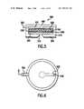
- FIG. 5is a cross-section view of the fluid collection and sensor device of FIG. 4 , shown in assembled form.
- FIG. 6is a top view of the fluid collection and sensor device of FIG. 4 .
- FIG. 7is a cross-section view of a portion of a fluid collection and sensor device illustrating treatment of various components of the device with agents according to another aspect of the invention.
- FIG. 8is a partial cross-section view of a portion of a fluid collection and sensor device featuring a movable reservoir for removing fluid from the sensor according to another embodiment of the invention.
- FIG. 9is a partial cross-section view of a portion of a fluid collection and sensor device featuring an active suction and purge media arrangement according to yet another embodiment of the invention.
- FIG. 10is a partial cross-section view of a portion of a fluid collection and sensor device featuring one or more valves for controlling evaporation of fluid in the fluid flow path.
- FIG. 11is a diagram showing a fluid collection and sensor featuring a membrane or cover that controls evaporation of fluid in the device.
- FIG. 12is a diagram showing a fluid collection and sensor device featuring a capillary channel step-and-sip fluid control mechanism.
- FIG. 13is a diagram showing a fluid collection and sensor device featuring an intermediate reservoir useful in controlling fluid contact with the sensor.
- FIG. 14is a diagram showing a fluid collection and sensor device featuring a micro-capillary tube that is useful in controlling introduction of new fluid onto a sensor.
- FIG. 15is a detailed diagram of the micro-capillary tube forming a part of the device shown in FIG. 14 .
- FIG. 16is a partial sectional view of a portion of the micro-capillary tube showing the sensor electrodes incorporated in the wall of the micro-capillary tube.
- tissuemeans an aggregate of cells of a particular kind, together with their intercellular substance, that forms a structural material. At least one surface of the tissue is preferably, but not necessarily, accessible to electromagnetic radiation so that one embodiment of the invention can be carried out.
- the preferred tissueis the skin.
- Other tissues suitable for use with this inventioninclude mucosal tissue and soft organs.
- biological membranemeans the outer layer of an organism, such as skin or mucous membrane, the structure separating one area of an organism from another, such as a capillary wall, or the outer layer of an organism which separates the organism from its external environment, such as skin, buccal mucosa or other mucous membrane.
- biological fluidmeans blood serum, whole blood, interstitial fluid, lymph fluid, spinal fluid, plasma or any combination of these fluids.
- Interstitial fluidmeans the clear fluid that occupies the space between the cells in the body.
- microporationmeans the formation of a small hole, opening or pore to a desired depth in or through a biological membrane, such as skin or mucous membrane, or the outer layer of an organism to lessen the barrier properties of this biological membrane to the passage of biological fluids, such as analytes from within the biological membrane or the passage of permeants or drugs from without the biological membrane into the body for selected purposes, or for certain medical or surgical procedures.
- the size of the hole or “micropore” so formedis approximately 1-1000 ⁇ m in diameter. It is to be understood that the term “micropore” is used in the singular form for simplicity, but that it multiple openings or pores may be formed by the integrated device according to the present invention.
- artificial openingmeans any physical breach of the biological membrane of a suitable size for delivering a compound or extracting a fluid therethrough, including micropores.
- suctionor “pressure” relates to the relative pressure as compared to the internal pressure of the organism to which the system is interfaced. “Vacuum” is used synonymously with the term “suction.”
- integrated devicemeans a device suitable for forming small holes or micropores in tissue, collecting a biological fluid from the tissue (preferably through the micropores so created) and analyzing the biological fluid to determine a characteristic thereof.
- a fluid collection and sensor deviceis shown at reference numeral 100 as part of a continuous fluid collection and monitoring system, such as the system disclosed in commonly assigned U.S. application Ser. No. 09/357,471, entitled “System And Method For Continuous Analyte Monitoring,” filed on even date.
- the fluid collection and sensor device 100also called a tissue interface device, is designed to be positioned on or about the surface of a biological membrane (BM) to collect and monitor fluid that is harvested through one or more artificial openings created in the biological membrane.
- BMbiological membrane
- the fluid collection and sensor device 100comprises a sensor 110 and a waste fluid storage element 120 . These elements are contained within a flexible housing that is tissue-compatible.
- the device 100is coupled to a monitor and control unit 200 that includes a source of suction and acts as a controller for controlling the application of suction over the sensor 110 to draw biological fluid out of the tissue via one or more artificial openings in the biological membrane so that the fluid is transported and makes contact with the sensor 110 .
- a fluid flow path 105 for the biological fluidis defined in the device 100 for drawing the fluid from the tissue to the sensor 110 and ultimately to the waste fluid storage element 120 .
- Direction of fluid flowis shown by arrow 107 .
- the sensor 110may be any type of sensor, such as an analyte sensor that determines the concentration of an analyte in the biological fluid.
- a glucose sensoris an example.
- One or more electrically conductive and/or optic lead linesconnect the sensor to the monitor and control unit 200 .
- the lead lines from the sensormay be contained within a connector 300 that couples the monitor and control unit 200 to the fluid collection and sensor device 100 .
- the connectoralso communicates suction or positive pressure to the fluid collection and sensor device 100 .
- the lead linescan include one or more optical fiber elements useful to optically read the sensor 110 remotely from the monitor and control unit 200 if the sensor 110 is a type that is optically read.
- the device 100may contain a light source, detector, suitable optics and electronics to support the use of an optically read sensor 110 .
- the waste fluid storage element 120collects biological fluid after it has contacted the sensor 110 . Suction applied from the monitor and control unit 200 creates a pressure differential between the organism's internal pressure and that of the system to draw the fluid into the device 100 onto the sensor 110 and ultimately deposits the fluid into the waste fluid storage element 120 so that new samples of the biological fluid are drawn in to contact the sensor 110 for new an independent readings.
- the organism's internal pressureis, for example, tissue pressure, intercellular or interstitial pressure, lymph fluid pressure, arterial pressure, capillary blood pressure, possibly intracellular pressure, the internal pressure of an organ (kidney, brain, spinal cord, etc.), or pressure of an abnormal tissue mass (tumor, cyst, etc.).
- the fluidis collected and monitored on a continuous basis, at flow rates in the range of microliters per hour in order to obtain measurements on a periodic basis. Because small fluid volumes are continuously collected by the device 100 , over a period of several hours to many days, it is practical to utilize a waste storage element 120 to store the fluid that has already been sensed by the sensor 110 .
- the volume capacity of the waster fluid storage element 120is variable depending on the application. A range is, for example, of 0.1 mL to 2 mL.
- the waste fluid storage element 120may comprise one or more layers of mesh wicking material that wicks fluid away or off of the sensor 110 .
- the mesh layerwould be designed to wick off the fluid only after it has been on the sensor 110 for a sufficient period of time to allow a measurement. This could be controlled by fabricating the mesh layer with a specified surface tension so that it can wick fluid away from the sensor no faster than a certain rate to ensure that the fluid has made contact with the sensor 110 for a sufficient period of time.
- the waste fluid storage elementcomprises a reservoir that includes one or more layers of wicking material therein to absorb fluid collected in the reservoir. The surface tension effects of the mesh layer are controlled by selection of materials, type of weave used, three dimensions, treatment of the mesh with surface tension modifiers such as surfactants, hydrophobic compounds, or any combinations of these techniques as is well known in the art.
- FIGS. 2 and 3illustrate an embodiment of a fluid collection and sensor device 400 comprising a waste fluid reservoir 420 positioned downstream of a sensor 410 . Fluid flows out of the tissue across the sensor 410 and then into the waste fluid reservoir 420 .
- a mesh element 405is placed over the sensor 410 .
- the mesh element 405is optionally fabricated to promote an even, bubble-free fluid flow across the sensor 410 .
- This mesh element 405is optionally treated with various compounds such as surface tension modifiers, such as a surfactant, to assist in controlling the fluid flow across the sensor, or agents designed to keep the sensor element free from protein aggregation, protein agglutination, fibrinogenosis, cellular attachment, bacterial growth, or sepsis, as well as to prevent the blocking or reduction of fluid flow across the sensor.
- the reservoir 420is preferably made from a suitable absorptive media such as a bonded fiber material that is commonly used in liquid transfer wicks or filters. For example, these materials may be made by bonding cellulose acetate, polyester, nylon or polyolefin fibers.
- the fibersare optionally oriented to promote movement of the biological fluid in the flow path across the sensor 410 and into the reservoir 420 .
- An example of a suitable reservoiris a media sold by Filtrona Richmond, Inc. under the trademark TransorbTM, which is commonly used as downstream absorptive media in flow-through diagnostic devices and in other applications requiring absorption and retention of excess liquid.
- the fluid collection and sensor device 500comprises a tissue interface member 510 , a channel adhesive layer 520 , an electrode substrate layer 530 , an absorbent reservoir layer 540 , an optional barrier layer 550 (which is optionally treated so as to be hydrophobic) and a top layer 560 .
- the tissue interface member 510is formed of a pliable material and has a contoured hole 512 which is aligned with one or more openings in the biological membrane when in use.
- a tissue adhesive layer 505is optionally provided on the bottom of the tissue interface member 510 to attach to a surface of a biological membrane and form a pneumatic seal thereto, as well as to maintain continuous registration of the contoured hole 512 (referred to hereinafter) with the artificial openings formed in the organism.
- the radius profile of this holeis important for maximizing the flux of fluid while minimizing local trauma to adjacent tissues.
- An effective range for the radius of this contoured holeis 0.1 mm to 10 mm.
- This contourmay have a changing radius shape, such as that of an exponential curve or hyperbolic curve.
- the channel adhesive layer 520fits within the tissue interface member 520 and comprises a channel 522 that is laser or die cut therein.
- the channel adhesive layer 520serves as a pneumatic seal around the channel 522 and to limit the volume of fluid exposed to the sensor (electrodes 532 referred to hereinafter).
- One end of the channel 522 in the channel adhesive layeris aligned with the hole 512 in the tissue interface member 510 .
- the electrode substrate layer 530comprises several electrodes 532 (such as a working electrode, counter electrode and reference electrode) that are disposed on the bottom surface of the layer 530 .
- the electrode substrate layer 530is formed of a polyester substrate material. Extending off of the electrode substrate layer 530 is an electrical connector 534 that contains leads which are electrically connected to the electrodes 532 .
- a small hole 536is provided in the electrode substrate layer 530 that communicates vacuum to the lower portions of the device 500 (in particular the channel 522 and the contoured hole 512 ) through which fluid is drawn upwards across the electrode substrate layer 530 .
- the electrode substrate layer 530is essential the sensor element of the fluid collection and sensor device 500 .
- the electrodes 532are formed on the electrode substrate layer 530 using screen printing, lithographic techniques, masked electro-deposition techniques, die or laser cut layers bonded to adjacent layers, or any combination of these methods or other suitable technologies known in the art.
- a flow path for the biological fluidis defined in the device 500 by the hole 512 in the tissue interface member 510 and adhesive layer 505 , channel 522 in the channel adhesive layer 520 and hole 536 in the electrode substrate layer 530 that leads to the absorbent reservoir layer 540 .
- the absorbent reservoir layer 540is formed of the materials described above in conjunction with FIGS. 2 and 3 .
- the optional barrier layer 550may be formed of a suitable hydrophobic material, such as PTFE, Hyrdolon Nylon 6,6 (sold by Pall Specialty Materials, Port Washington, N.Y.) with a suitable pore diameter (0.2 ⁇ m to 0.22 ⁇ m) commonly used in membranes that filter fluid vapor from vacuum lines.
- the hydrophobic membrane layer 550allows air to pass but blocks aerosols and aqueous liquids from passing through therethrough.
- the membrane material selectedhas pores of sufficiently small diameter to restrict movement of fluid, yet large enough to not create a pressure drop across the membrane. Such a pressure drop would have the result of decreasing the vacuum pressure at the sensor and reservoir level ( 512 , 522 , 536 , and 540 ) of the fluid channel than that which would be detected by the pressure sensor near the vacuum pump (in 200 ).
- the top layer 560is formed of a suitable pliable material such as thin acrylic.
- a vacuum port 562is provided on one end of the top layer 560 to communicate vacuum to the device 500 .
- a region of empty space 570may be provided between the top layer 560 and the hydrophobic membrane layer 550 (if it is included) or between the top layer 560 and the absorbent reservoir layer 540 (if the barrier layer 550 is not included).
- the space 570also serves to extend the useful lifetime of the hydrophobic membrane layer 550 .
- the region of empty spacemay be positioned between the electrode substrate layer 530 and the absorbent reservoir layer 540 .
- the dimensions of the fluid collection and sensor device 500vary depending on a particular application.
- the external dimensions of the tissue interface member 510ranges in height from 1 mm to 10 mm and in diameter from 10 mm to 30 mm., with a total internal fluid volume capacity ranging from 10 ⁇ L to more than 2.0 mL.
- the electrode substrate layer 530is for example 250 ⁇ m thick.
- the absorbent reservoir layer 540is 2 mm thick.
- the optional barrier layer 550 (whether hydrophobic or not) 550is 50 ⁇ m thick and the top layer 560 is 1 mm thick. For a particular reservoir material, there may be approximately 80-85% void volume or empty space available for fluid.
- the thickness of the of the disc-shaped waste fluid reservoir element 540 required to hold 1 mLis approximately 2.5 mm.
- the reservoir layeris preferably capable of storing approximately 1 mL of fluid to accommodate a filling rate of 10 ⁇ L/hr over 72 hours.
- the fluid collection and sensor device 500is positioned on or about a biological membrane in which one or more artificial openings have been formed from which biological fluid will be harvested. Suction is applied at the port 562 to draw fluid into the device through the hole 512 and via the channel 522 in the adhesive layer 520 across the electrode substrate layer 530 . As fluid is drawn across the electrode substrate layer 530 , it is ultimately pulled through the hole 536 and into the absorbent reservoir layer 540 . In addition, the capillary/wicking action of the absorbent reservoir layer 540 assists in pulling fluid into it. Fluid drawn across the electrode substrate layer 530 will be present for a sufficient amount of time in order to obtain an accurate reading of that sample of fluid, before it is drawn into the absorbent reservoir layer 540 .
- the amount of suction applied to the device 500 and the wicking force of the absorbent reservoir layer 540are controlled to ensure that the fluid stays on the electrode substrate layer 530 long enough to obtain an accurate reading. For example, it has been shown experimentally that a suction level of 1 ⁇ 4 to 1 ⁇ 2 atmospheres and a TransorbTM wicking material achieves a sufficient dwell time on the sensor for accurate readings to be achieved.
- the optional hydrophobic membrane layer 550prevents any of the biological fluid vapor from getting further downstream in the system and potentially contaminating the pump or pressure transducer.
- the hydrophobic membrane layer 550provides a protective barrier to prevent contagious diseases from being spread between patients during successive uses of a monitor and control unit 200 .
- the region 570 of empty space, if provided between the electrode substrate layer 530 and the absorbent reservoir layer 540is useful to avoid clogging at the junction thereof. Fluid will fill the region of empty space prior to being drawn into the absorbent reservoir layer 540 .
- the material used in forming the absorbent reservoirmay be treated with an anti-coagulant, anti-microbial or protease-active material to limit protein precipitation or build-up by other substances found in biological fluid (such as in blood or interstitial fluid) which may cause blockage at the entry point to the absorbent reservoir.
- the channel in the adhesive layermay be treated with an anti-coagulant, anti-microbial or protease-active material material.
- Other substancesmay be used to treat various portions of the device to maintain fluid flow, including anti-microbials, collagenase, surfactants, hydrophilic substances, hydrophobic substances, or combinations thereof.
- Another aspect of the inventionis to treat various components of the fluid collection and sensor device with one or any combination of an anti-coagulant agent, anti-microbial agent or collagenase agent to prevent fibrin or protein build-up, sepsis and subsequent degradation or clogging of the flow path.
- an anti-coagulant agentanti-microbial agent or collagenase agent
- FIG. 7this aspect is described in greater detail.
- the reservoir layer and the adhesive layerare omitted to illustrate aspects of the invention that do not necessarily require the provision of these elements.
- the adhesive layeris not included in this embodiment, the channel is cut in the electrode substrate layer 530 instead.
- the fluid path referred to aboveis shown particularly at reference numeral 580 .
- surfaces of the fluid flow path 580are treated with an anti-coagulant agent 590 .
- the components of the device 500 that are treatedinclude the surfaces of the opening 512 in the tissue interface member 510 , the surfaces of the channel that is made in the electrode substrate layer 530 , and the surfaces of the flow path that lead to the vacuum port 562 .
- each of these components 510 , 512 , 530 and 562are fabricated with a material embedded with some or all of these treatment compounds, in a manner similar to known controlled release implants or patch drug delivery systems.
- a suitable anti-coagulant agentis a heparin-based agent.
- One procedure to treat the surfaces with a heparin-based agentis as follows. Several mL of a Heparin-Benzalkonium Chloride (H-BAC) solution with a concentration of 720 units of heparin was loaded into a syringe with a luer connector. The syringe is connected to the vacuum port end of the tubing portion of the connector 300 ( FIG. 1 ) and the H-BAC solution is introduced into the tubing until the entire tubing and the fluid flow path of the fluid collection and sensor device is filled up, making sure there are no bubbles present.
- H-BACHeparin-Benzalkonium Chloride
- H-BAC solutionis retracted back into the syringe or push through the device into another container.
- the deviceis connected to a high-pressure air source and air is run through the devices for 2-3 minutes to remove any solution remaining in the device.
- the deviceis then allowed to dry for several hours at ambient temperature, or the drying process can be expedited by drying it at a higher temperature for several minutes.
- Some other anti-coagulant agentsinclude salicylic acid (aspirin), hyaluaronidase, various protease active agents such as collagenase, dilute solutions of ammonia, EDTA, apotinin, and a host of other compounds well known in the art and common in a standard clinical laboratory.
- the components of the fluid flow pathare optionally treated with anti-bacterial agents to prevent an infection (bacteria) from growing in the fluid collection device and reaching further downstream in the system (even if a hydrophobic barrier layer is provided).
- anti-microbial productsare also suitable, such as iodine, betadine, bacitracin, chlorophyll, EDTA, polysorbate-80, and apotinin, all of which could be incorporated as a surface treatment, or embedded in these components.
- the components of the fluid flow path in the devicecan be treated by various surface modification techniques such as gas plasma, flame, chemical or corona discharge.
- the surfacecan be modified with the optimal surface charge and charge density in order to prevent binding of the components of the biological fluid and to maintain sufficient wettability of the surfaces.
- the treatmentis applied such that the resultant net charge of the surface after modification is positive, negative or neutral.
- the fluid collection and sensor deviceis optionally manufactured using micro-lithographic techniques as described in U.S. Provisional Application No. 60/092,731 filed Jul. 14, 1998, entitled “Integrated Device for Collecting a Micro-Fluid Sample and Assaying of Sample Utilizing Micro-Lithographic Bio-Sensor Component,” the entirety of which is incorporated herein by reference.
- Micro-lithographic fabrication techniquesare useful in constructing the sort of precision, micro-fluidic pathways and structures.
- micro-fluid managementcould also be realized if the geometry of the tissue interface device were formed such that over the broad areas of the enzyme-laden portion of the sensor, a series of micro-channels or perforations are made that increases the ratio of surface area to internal volume of the porous sensor thereby facilitating a more rapid uniform wetting of the entire porous element and similarly rapid and complete “un-wetting” during the blotter removal phase to clear the old fluid away.
- FIG. 8another embodiment of a fluid collection and sensor device 600 is shown featuring a movable reservoir 610 in the form of a blotting element that is controllably positioned into and out of contact with the sensor 620 by an actuator mechanism 630 .
- the actuator mechanism 630is, for example, a miniaturized solenoid or other suitable mechanism capable of moving the blotting element into and out of contact with the sensor 610 .
- This configurationachieves the delivery of fresh fluid in sufficient amounts to the sensor 610 on demand by momentarily moving the blotting element into contact with the sensor 620 to remove all previous fluid from the active regions and thereby ensure that the next assay reading would be made on a substantially new and current fluid sample.
- the material of the blotting elementmay be any one of the aforementioned absorbent materials useful for the reservoir described in the previous embodiments.
- FIG. 9illustrates an embodiment of a fluid collection and sensor device 700 featuring two other ways to remove “old” fluid from the sensor.
- One configurationcomprises a fluid suction mechanism interfaced to the sensor such that when activated, old fluid is drawn off of the sensor.
- the sensor 710is placed within a small channel 720 defined by the tissue interface member, enclosed on all sides with both ends open.
- One end of the channel 720is connected to a suction source (in the monitor and control unit 200 ) and the other end is connected to the fluid source 730 , i.e., the fluid sample from the biological membrane.
- a suction sourcein the monitor and control unit 200
- application of suctionis applied to the channel 720 to flush the old fluid out of the sensor 710 .
- a valve 725is positioned over the entrance to the channel 720 to allow the suction to remove the old fluid.
- the valve 725is controlled to open and thereby allows the suction force that is currently on in the channel 720 to flush the channel 720 .
- the suction forcecould be increased as well.
- the valve 725is closed, the fluid can again be pulled from the fluid source 730 and refill the channel 720 .
- the dimensions of the channel 720 and the sensor 710are made to contain a total volume of only a few microliters of fluid. Therefore, the fluid harvesting flux rates ensure that a volume of fluid is replaced completely every 30 seconds or less, thereby ensuring that readings taken periodically every 30 seconds will be largely independent of previous flow sample readings.
- This “flow purging”is optionally enhanced by adding a reservoir 740 of a purge media, such as water or an air bubble, that flushes the sensor 710 clean of the old fluid as the suction moved old fluid off of the sensor 710 prior to the introduction of the new fluid.
- a purge mediasuch as water or an air bubble
- a small valve 750 controlled by an actuator 760opens or closes to control when the purging media is released across the sensor 710 .
- the valve 750is opened to release the purge media and is closed when a fresh fluid measurement is to be made, while keeping the suction on the channel 720 active through these cycles.
- the use of an air bubbleeffectively demarcates the segments of biological fluid in time and does not allow adjacent fluid segments to affect each other.
- the use of wateris not optimal in terms of maintaining the separation of fluid segments and hence analyte concentration in time, but allows the addition of aqueous agents.
- the purge mediais optionally formulated to contain the anti-coagulants, anti-microbials, or other fluid management compounds that are useful in maintaining the integrity of the sensor and the overall functionality of the fluid collection and sensor device.
- Micro-lithographic, direct laser machining, electro-forming fabrication techniques or molds made from masters using these techniquesare very useful in constructing the sort of precision, micro-fluidic pathways and structures.
- An enhancement of the micro-fluid managementcould also be realized if the geometry of the tissue interface device were formed such that over the broad areas of the enzyme laden portion of the sensor, a series of micro-channels or perforations are made that increases the ratio of surface area to internal volume of the porous sensor thereby facilitating a more rapid uniform wetting of the entire porous element and similarly rapid and complete “un-wetting” during the blotter removal phase to clear the old fluid away.
- the device 800 shown in FIG. 10features a sensor 810 , a waste fluid storage element 820 (with an optional layer of absorbing material 822 ), a valve 830 between the sensor 810 and the waster fluid storage element 820 , a valve 840 , a filter 850 , a reservoir 860 for containing a flushing fluid within an elastic bag 865 , a gas permeable membrane 870 and a valve 875 . Suction is applied from the monitor and control unit 200 either continuously (after the artificial openings are formed) or only prior to or during a sensor reading event.
- valve 830placed in the fluid flow path 825 is closed, so that natural evaporation of excess fluid in the fluid flow path 825 occurs when the vacuum (or pressure) is not running. If the vacuum is shut off but not released, there still may be vacuum pressure in the fluid flow path 825 and thus natural evaporation could not occur, but rather vacuum pressure assisted evaporation could.
- the valve 830is, for example, an impermeable flap.
- a sensor mounted externally on the device 800is optional to detect when a shower, bath, rain or other ultra-high humidity condition is present to control activation of suction and appropriate valve control to maintain system integrity and functionality under these conditions.
- the operation of the reservoir 860 and, valve 840is similar to that described above in conjunction with FIG. 9 .
- the gas permeable membrane 870is optionally used in place of the valve 875 to allow air to flow into the reservoir 860 to displace the volume of the reservoir during flushing of the channel 825 .
- the configuration of FIG. 10is suitable for operation independent of the orientation of the device 800 on a tissue surface, such as the forearm of an individual, which is typically moving frequently, because the fluid contained in the elastic bag exerts continuous pressure on the fluid against the valve 840 .
- the function of the valve 830is also achieved with a reservoir 880 (that acts as the waste fluid storage element) having a membrane or cover 872 made of breathable material, such as GoreTexTM material.
- the cover 872provides a vacuum tight seal when wetted with fluid, but still allows fluid to evaporate through the breathable membrane to remove fluid from the reservoir.
- the cover 872is arranged to wet itself when vacuum is applied by bending down to touch the reservoir, but when vacuum is removed, the cover 872 would pull back up (as shown in phantom) and eventually dry to become permeable to water vapor, allowing the reservoir to dry out (but not to dry completely). In this scenario the reservoir 880 would be pre-wetted at manufacture.
- the membrane 872is optionally treated with a protease active compound to prevent formation of skin over the membrane from protein and fibrin components in the biological fluid.
- FIG. 12another embodiment is shown wherein the fluid collection and sensor device 900 is optionally treated with a hydrophobic material that is transferred to the BM in order to cause the creation of fluid droplets 921 (as opposed to a continuous stream).
- the tissue interface deviceprovides a physical reference to the artificial openings and fluid from each artificial opening.
- An actuator 922 and a capillary sipper 923(e.g., a capillary tube) form a step-and-sip mechanism.
- the capillary tubehas a first (input) end through which fluid is collected and a second end from which fluid is transported to the sensor 910 .
- the actuator 922moves the input end of the capillary sipper 923 sequentially to each fluid drop 921 .
- Fluidmoves through the capillary sipper 923 (as a result of the surface tension forces in the capillary tube) and out its second (output) end to make contact the sensor 910 .
- Fluidis efficiently collected directly into the capillary tube 923 that feeds the sensor 910 with very little fluid waste to extraneous surface areas that exist in a passive fluid management configuration. This configuration is useful with or without the treatment of a hydrophobic compound.
- FIG. 13another embodiment is shown wherein the flow of sample fluid to the sensor is managed such that it is presented to the sensor in a fashion compatible with the proper performance of the sensor.
- the deviceshown at reference numeral 1000 , comprises a sensor 1010 , a first or intermediate reservoir 1020 , a volume sensor 1030 , a waste reservoir 1040 , and a check valve 1050 .
- Suctionis applied to the device 1000 via a suction port 1060 .
- the intermediate reservoir 1020accumulates the harvested fluid sample during the harvesting process until a sufficient volume of the fluid sample is obtained.
- the volume sensor 1030detects when a sufficient volume of fluid has been collected in the intermediate reservoir 1020 .
- the volume sensor 1030is, for example, an electrical sensor, optical sensor, sonic sensor or the like and sends a signal to the monitor and control unit 200 alerting it that the tissue interface device can deliver the sample to the sensor 1010 .
- suctionis applied initially to draw fluid into the intermediate reservoir 1020 .
- the monitor and control unit 200replaces the suction with a mild pressure for a controlled time period, causing the check valve 1050 to open and force fluid onto the sensor 1010 .
- the fluidis allowed to dwell on the sensor 1010 for a sufficient period of time to obtain a reading.
- the monitor and control unitapplies an additional small amount of pressure to force the fluid from the sensor 1010 to the waste reservoir 1040 .
- the application of suctioncloses the check valve and induces fresh fluid to enter the intermediate reservoir 1020 , and the process repeats.
- FIGS. 14-16another embodiment is shown featuring electrodes of an electrochemical bio-sensor which are disposed on the inside walls of a micro-capillary tube.
- the device 1100comprises a housing 1101 , a tissue interface element or member 1105 having a contoured interface hole 1115 , a capillary tube 1120 and a sensor 1125 disposed on an interior wall of the capillary tube 1120 .
- a sensor interconnect fitting 1130is mounted on the outside wall of the capillary tube 1120 and feeds the electrical lead lines 1135 to a hole in the fluid collection device housing 1101 .
- An optional translation stage 1140provides translation which may be required to gain access to all of the fluid bead, depending on the size of the capillary tube 1120 used and the number of artificial openings 1110 made in the organism.
- Electrical leads 1130connect to the sensor 1125 , which are in turn, connected to the monitor and control unit 200 .
- a fluid wicking and evaporation element 1150(such as a fiber plug) is provided at one end of the capillary tube.
- the sensor 1125includes sensor electrode wires 1126 that are disposed on inside walls of the capillary tube 1120 using any known technique suitable therefor.
- the electrode wires 1126comprise a working electrode (W), a counter electrode (C) and a reference electrode (R).
- the device 1100is aligned with one or more artificial openings 1110 .
- the biological fluidis drawn out of the artificial opening(s) 910 in the organism through the contoured hole 1115 in the tissue interface element 1105 and forms a bead of fluid 1112 at the surface of the biological membrane of the organism.
- the capillary tube 1120may be coated by various agents to enhance the capillary action of the tube. As the fluid moves up the capillary tube 1120 , it comes into contact with the sensor 1125 which is mounted on the inside wall of the capillary tube 1120 .
- the fluid collection device 1100is under vacuum pressure from the monitor and control unit 200 through the vacuum port 1160 .
- the vacuum chamber formed by the device housing 1101 and the tissue interface element 1105is optionally pre-humidified to reduce errors due to the evaporation of the biological fluid as it comes out of the artificial openings in the organism.
- optical detection of the analyte of interestis utilized. An optical fiber is substituted for the electrode wires 1126 in the sensor 1125 and for the electrical wires 1135 for use with an optically read sensor. The rate of sample change is as rapid as new fluid sample is made available. In this manner, evaporation of the sample under measurement is minimized.
- the capillary tubeis constructed in such a manner that its thickness (optical path) can be varied in a manner similar to the dimensional changes used in pulse oximetry. From the introduction of a simulated photoplethysmographic waveform, the optical absorption is measured at various wavelengths and at multiple absorption path lengths allowing a ratio-metric calculation to measure the levels of a specific analyte desired.
- the site on the BM where the artificial openings are to be formedmay be treated with a ring-shaped area of a hydrophobic material, except for an area defining a capillary or wicking channel that abuts the site. This treatment facilitates delivery of the biological fluid into the device.
Landscapes
- Health & Medical Sciences (AREA)
- Life Sciences & Earth Sciences (AREA)
- Engineering & Computer Science (AREA)
- Physics & Mathematics (AREA)
- Surgery (AREA)
- Animal Behavior & Ethology (AREA)
- Pathology (AREA)
- Veterinary Medicine (AREA)
- Biomedical Technology (AREA)
- Heart & Thoracic Surgery (AREA)
- Medical Informatics (AREA)
- Molecular Biology (AREA)
- Public Health (AREA)
- General Health & Medical Sciences (AREA)
- Biophysics (AREA)
- Hematology (AREA)
- Dermatology (AREA)
- Optics & Photonics (AREA)
- Manufacturing & Machinery (AREA)
- Pain & Pain Management (AREA)
- Emergency Medicine (AREA)
- Immunology (AREA)
- Vascular Medicine (AREA)
- Sampling And Sample Adjustment (AREA)
Abstract
Description
Claims (44)
Priority Applications (3)
| Application Number | Priority Date | Filing Date | Title |
|---|---|---|---|
| US09/357,452US7037277B1 (en) | 1998-07-21 | 1999-07-20 | System and method for fluid management in a continuous fluid collection and sensor device |
| PCT/US2000/016507WO2000078208A1 (en) | 1999-06-18 | 2000-06-15 | System and method for monitoring glucose to assist in weight management and fitness training |
| AU54906/00AAU5490600A (en) | 1999-06-18 | 2000-06-15 | System and method for monitoring glucose to assist in weight management and fitness training |
Applications Claiming Priority (4)
| Application Number | Priority Date | Filing Date | Title |
|---|---|---|---|
| US9353498P | 1998-07-21 | 1998-07-21 | |
| US13873999P | 1999-06-11 | 1999-06-11 | |
| US13997099P | 1999-06-18 | 1999-06-18 | |
| US09/357,452US7037277B1 (en) | 1998-07-21 | 1999-07-20 | System and method for fluid management in a continuous fluid collection and sensor device |
Publications (1)
| Publication Number | Publication Date |
|---|---|
| US7037277B1true US7037277B1 (en) | 2006-05-02 |
Family
ID=36215972
Family Applications (1)
| Application Number | Title | Priority Date | Filing Date |
|---|---|---|---|
| US09/357,452Expired - Fee RelatedUS7037277B1 (en) | 1998-07-21 | 1999-07-20 | System and method for fluid management in a continuous fluid collection and sensor device |
Country Status (1)
| Country | Link |
|---|---|
| US (1) | US7037277B1 (en) |
Cited By (25)
| Publication number | Priority date | Publication date | Assignee | Title |
|---|---|---|---|---|
| US20030191376A1 (en)* | 1998-07-21 | 2003-10-09 | Samuels Mark A. | System and method for continuous analyte monitoring |
| US20050245844A1 (en)* | 2004-05-03 | 2005-11-03 | Mace Chad H | Analyte test device |
| US20060015019A1 (en)* | 2002-06-25 | 2006-01-19 | Watt Paul W | Wound fluid collecting and indicating device |
| US20070193342A1 (en)* | 2006-02-17 | 2007-08-23 | Bailey Douglas S | Sensor for detecting hydrocarbons |
| WO2007144883A1 (en) | 2006-06-13 | 2007-12-21 | Ben Gurion University Of The Negev Research And Development Authority | System and method for transfetal (amnion-chorion) membranes transport |
| US20100256465A1 (en)* | 2009-03-02 | 2010-10-07 | Seventh Sense Biosystems, Inc. | Devices and techniques associated with diagnostics, therapies, and other applications, including skin-associated applications |
| US20110105951A1 (en)* | 2009-10-30 | 2011-05-05 | Seventh Sense Biosystems, Inc. | Systems and methods for treating, sanitizing, and/or shielding the skin or devices applied to the skin |
| US20110105952A1 (en)* | 2009-10-30 | 2011-05-05 | Seventh Sense Biosystems, Inc. | Relatively small devices applied to the skin, modular systems, and methods of use thereof |
| WO2012009613A1 (en)* | 2010-07-16 | 2012-01-19 | Seventh Sense Biosystems, Inc. | Low-pressure environment for fluid transfer devices |
| US20140005569A1 (en)* | 2010-10-22 | 2014-01-02 | C.Miethke Gmbh & Co Kg | Implant for measuring the intracorporeal pressure with telemetric transmission of the measured value |
| US20140152323A1 (en)* | 2012-12-05 | 2014-06-05 | Molex Incorporated | Flexible Fluid Level Sensor With Improved Measurement Capability |
| US8808202B2 (en) | 2010-11-09 | 2014-08-19 | Seventh Sense Biosystems, Inc. | Systems and interfaces for blood sampling |
| US8821412B2 (en) | 2009-03-02 | 2014-09-02 | Seventh Sense Biosystems, Inc. | Delivering and/or receiving fluids |
| US9033898B2 (en) | 2010-06-23 | 2015-05-19 | Seventh Sense Biosystems, Inc. | Sampling devices and methods involving relatively little pain |
| US9041541B2 (en) | 2010-01-28 | 2015-05-26 | Seventh Sense Biosystems, Inc. | Monitoring or feedback systems and methods |
| US20150209114A1 (en)* | 2014-01-29 | 2015-07-30 | Becton, Dickinson And Company | System and Method for Collection Confirmation and Sample Tracking at the Clinical Point of Use |
| US9119578B2 (en) | 2011-04-29 | 2015-09-01 | Seventh Sense Biosystems, Inc. | Plasma or serum production and removal of fluids under reduced pressure |
| US9295417B2 (en) | 2011-04-29 | 2016-03-29 | Seventh Sense Biosystems, Inc. | Systems and methods for collecting fluid from a subject |
| US10240965B2 (en) | 2012-12-05 | 2019-03-26 | Molex, Llc | Flexible fluid level sensor with improved measurement capability |
| SE1751628A1 (en)* | 2017-12-22 | 2019-06-23 | Brighter Ab Publ | Skin patch for diagnosis comprising an evaporation layer |
| US10543310B2 (en) | 2011-12-19 | 2020-01-28 | Seventh Sense Biosystems, Inc. | Delivering and/or receiving material with respect to a subject surface |
| US10675451B2 (en) | 2010-10-22 | 2020-06-09 | Christoph Miethke Gmbh & Co Kg | Hydrocephalus shunt arrangement and components thereof for draining cerebrospinal fluid in a patient having hydrocephalus |
| US11177029B2 (en) | 2010-08-13 | 2021-11-16 | Yourbio Health, Inc. | Systems and techniques for monitoring subjects |
| US11202895B2 (en) | 2010-07-26 | 2021-12-21 | Yourbio Health, Inc. | Rapid delivery and/or receiving of fluids |
| US20220054053A1 (en)* | 2019-04-08 | 2022-02-24 | Nippon Telegraph And Telephone Corporation | Wearable Sensor and Sweating Analysis Device |
Citations (27)
| Publication number | Priority date | Publication date | Assignee | Title |
|---|---|---|---|---|
| US3847138A (en) | 1973-03-14 | 1974-11-12 | S Gollub | Method and system for controlled automated administration of drugs to patients |
| US4006743A (en) | 1973-01-15 | 1977-02-08 | The Johns Hopkins University | System for continuous withdrawal of blood |
| GB1498332A (en) | 1975-01-22 | 1978-01-18 | Hospital For Sick Children | Artificial beta cell and computer programmed therefor |
| US4151845A (en) | 1977-11-25 | 1979-05-01 | Miles Laboratories, Inc. | Blood glucose control apparatus |
| US4409966A (en) | 1981-05-29 | 1983-10-18 | Lambrecht Richard M | Method and apparatus for injecting a substance into the bloodstream of a subject |
| US4832034A (en) | 1987-04-09 | 1989-05-23 | Pizziconi Vincent B | Method and apparatus for withdrawing, collecting and biosensing chemical constituents from complex fluids |
| WO1994006019A1 (en) | 1992-08-28 | 1994-03-17 | Via Medical Corporation | Calibration solutions useful for analyses of biological fluids and methods employing same |
| EP0596615A1 (en) | 1992-10-30 | 1994-05-11 | Medtronic, Inc. | Articles having bioactive surfaces |
| WO1994009713A1 (en) | 1992-10-28 | 1994-05-11 | Venisect, Inc. | Laser perforator |
| WO1994014062A1 (en) | 1992-12-11 | 1994-06-23 | Sudor Partners | Method and apparatus for determination of chemical species in perspiration |
| US5339830A (en) | 1992-01-21 | 1994-08-23 | Blake Joseph W Iii | Blood coagulation test system |
| US5458140A (en) | 1993-11-15 | 1995-10-17 | Non-Invasive Monitoring Company (Nimco) | Enhancement of transdermal monitoring applications with ultrasound and chemical enhancers |
| WO1996000110A1 (en) | 1994-06-24 | 1996-01-04 | Cygnus, Inc. | Iontophoretic sampling device and method |
| US5582184A (en) | 1993-10-13 | 1996-12-10 | Integ Incorporated | Interstitial fluid collection and constituent measurement |
| WO1997004832A1 (en) | 1995-07-25 | 1997-02-13 | Massachusetts Institute Of Technology | Enhanced transdermal transport using ultrasound |
| WO1997012242A1 (en) | 1995-09-27 | 1997-04-03 | Mercury Diagnostics Inc. | Direct reading chemical test strip for aqueous solutions |
| US5640954A (en) | 1994-01-19 | 1997-06-24 | Pfeiffer; Ernst | Method and apparatus for continuously monitoring the concentration of a metabolyte |
| WO1997038126A1 (en) | 1996-04-05 | 1997-10-16 | Mercury Diagnostics, Inc. | Methods and devices for determination of an analyte in body fluid |
| US5682233A (en) | 1995-09-08 | 1997-10-28 | Integ, Inc. | Interstitial fluid sampler |
| WO1997042883A1 (en) | 1996-05-17 | 1997-11-20 | Mercury Diagnostics, Inc. | Disposable element for use in a body fluid sampling device |
| WO1997042888A1 (en) | 1996-05-17 | 1997-11-20 | Mercury Diagnostics Inc. | Blood and interstitial fluid sampling device |
| WO1997043962A1 (en) | 1996-05-17 | 1997-11-27 | Mercury Diagnostics, Inc. | Methods and apparatus for expressing body fluid from an incision |
| US5697899A (en) | 1995-02-07 | 1997-12-16 | Gensia | Feedback controlled drug delivery system |
| EP0812570A1 (en) | 1996-06-11 | 1997-12-17 | Siemens-Elema AB | Arrangement for analysing body fluids |
| WO1998000193A1 (en) | 1996-07-03 | 1998-01-08 | Altea Technologies, Inc. | Multiple mechanical microporation of skin or mucosa |
| US5885211A (en) | 1993-11-15 | 1999-03-23 | Spectrix, Inc. | Microporation of human skin for monitoring the concentration of an analyte |
| US6071249A (en) | 1996-12-06 | 2000-06-06 | Abbott Laboratories | Method and apparatus for obtaining blood for diagnostic tests |
- 1999
- 1999-07-20USUS09/357,452patent/US7037277B1/ennot_activeExpired - Fee Related
Patent Citations (32)
| Publication number | Priority date | Publication date | Assignee | Title |
|---|---|---|---|---|
| US4006743A (en) | 1973-01-15 | 1977-02-08 | The Johns Hopkins University | System for continuous withdrawal of blood |
| US3847138A (en) | 1973-03-14 | 1974-11-12 | S Gollub | Method and system for controlled automated administration of drugs to patients |
| GB1498332A (en) | 1975-01-22 | 1978-01-18 | Hospital For Sick Children | Artificial beta cell and computer programmed therefor |
| US4151845A (en) | 1977-11-25 | 1979-05-01 | Miles Laboratories, Inc. | Blood glucose control apparatus |
| US4409966A (en) | 1981-05-29 | 1983-10-18 | Lambrecht Richard M | Method and apparatus for injecting a substance into the bloodstream of a subject |
| US4832034A (en) | 1987-04-09 | 1989-05-23 | Pizziconi Vincent B | Method and apparatus for withdrawing, collecting and biosensing chemical constituents from complex fluids |
| US5339830A (en) | 1992-01-21 | 1994-08-23 | Blake Joseph W Iii | Blood coagulation test system |
| WO1994006019A1 (en) | 1992-08-28 | 1994-03-17 | Via Medical Corporation | Calibration solutions useful for analyses of biological fluids and methods employing same |
| WO1994009713A1 (en) | 1992-10-28 | 1994-05-11 | Venisect, Inc. | Laser perforator |
| EP0596615A1 (en) | 1992-10-30 | 1994-05-11 | Medtronic, Inc. | Articles having bioactive surfaces |
| WO1994014062A1 (en) | 1992-12-11 | 1994-06-23 | Sudor Partners | Method and apparatus for determination of chemical species in perspiration |
| US5582184A (en) | 1993-10-13 | 1996-12-10 | Integ Incorporated | Interstitial fluid collection and constituent measurement |
| US5820570A (en) | 1993-10-13 | 1998-10-13 | Integ Incorporated | Interstitial fluid collection and constituent measurement |
| US5746217A (en) | 1993-10-13 | 1998-05-05 | Integ Incorporated | Interstitial fluid collection and constituent measurement |
| US5458140A (en) | 1993-11-15 | 1995-10-17 | Non-Invasive Monitoring Company (Nimco) | Enhancement of transdermal monitoring applications with ultrasound and chemical enhancers |
| US5885211A (en) | 1993-11-15 | 1999-03-23 | Spectrix, Inc. | Microporation of human skin for monitoring the concentration of an analyte |
| US5640954A (en) | 1994-01-19 | 1997-06-24 | Pfeiffer; Ernst | Method and apparatus for continuously monitoring the concentration of a metabolyte |
| WO1996000110A1 (en) | 1994-06-24 | 1996-01-04 | Cygnus, Inc. | Iontophoretic sampling device and method |
| US5697899A (en) | 1995-02-07 | 1997-12-16 | Gensia | Feedback controlled drug delivery system |
| WO1997004832A1 (en) | 1995-07-25 | 1997-02-13 | Massachusetts Institute Of Technology | Enhanced transdermal transport using ultrasound |
| US5682233A (en) | 1995-09-08 | 1997-10-28 | Integ, Inc. | Interstitial fluid sampler |
| WO1997012242A1 (en) | 1995-09-27 | 1997-04-03 | Mercury Diagnostics Inc. | Direct reading chemical test strip for aqueous solutions |
| WO1997038126A1 (en) | 1996-04-05 | 1997-10-16 | Mercury Diagnostics, Inc. | Methods and devices for determination of an analyte in body fluid |
| WO1997042885A1 (en) | 1996-05-17 | 1997-11-20 | Mercury Diagnostics, Inc. | Methods and apparatus for sampling body fluid |
| WO1997043962A1 (en) | 1996-05-17 | 1997-11-27 | Mercury Diagnostics, Inc. | Methods and apparatus for expressing body fluid from an incision |
| WO1997042882A1 (en) | 1996-05-17 | 1997-11-20 | Mercury Diagnostics, Inc. | Methods and apparatus for sampling and analyzing body fluid |
| WO1997042886A1 (en) | 1996-05-17 | 1997-11-20 | Mercury Diagnostics, Inc. | Body fluid sampling device and methods of use |
| WO1997042888A1 (en) | 1996-05-17 | 1997-11-20 | Mercury Diagnostics Inc. | Blood and interstitial fluid sampling device |
| WO1997042883A1 (en) | 1996-05-17 | 1997-11-20 | Mercury Diagnostics, Inc. | Disposable element for use in a body fluid sampling device |
| EP0812570A1 (en) | 1996-06-11 | 1997-12-17 | Siemens-Elema AB | Arrangement for analysing body fluids |
| WO1998000193A1 (en) | 1996-07-03 | 1998-01-08 | Altea Technologies, Inc. | Multiple mechanical microporation of skin or mucosa |
| US6071249A (en) | 1996-12-06 | 2000-06-06 | Abbott Laboratories | Method and apparatus for obtaining blood for diagnostic tests |
Non-Patent Citations (2)
| Title |
|---|
| "Controlled Removal of Human Stratum Corneum by Pulsed Laser" Jacques et al., 88 J. Invest. Dermatol., 88-93 (1987). |
| "Ultraviolet-Laser Ablation of Skin" Lane et al. 121 Arch. Dermatol., 609-617 (1985). |
Cited By (49)
| Publication number | Priority date | Publication date | Assignee | Title |
|---|---|---|---|---|
| US7384396B2 (en) | 1998-07-21 | 2008-06-10 | Spectrx Inc. | System and method for continuous analyte monitoring |
| US20030191376A1 (en)* | 1998-07-21 | 2003-10-09 | Samuels Mark A. | System and method for continuous analyte monitoring |
| US20060015019A1 (en)* | 2002-06-25 | 2006-01-19 | Watt Paul W | Wound fluid collecting and indicating device |
| US20050245844A1 (en)* | 2004-05-03 | 2005-11-03 | Mace Chad H | Analyte test device |
| US9101302B2 (en)* | 2004-05-03 | 2015-08-11 | Abbott Diabetes Care Inc. | Analyte test device |
| US8049638B2 (en) | 2006-02-17 | 2011-11-01 | Perma-Pipe, Inc. | Sensor for detecting hydrocarbons |
| US20110041588A1 (en)* | 2006-02-17 | 2011-02-24 | Perma-Pipe, Inc. | Sensor for detecting hydrocarbons |
| US20070193342A1 (en)* | 2006-02-17 | 2007-08-23 | Bailey Douglas S | Sensor for detecting hydrocarbons |
| US7525444B2 (en)* | 2006-02-17 | 2009-04-28 | Perma-Pipe, Inc. | Sensor for detecting hydrocarbons |
| WO2007144883A1 (en) | 2006-06-13 | 2007-12-21 | Ben Gurion University Of The Negev Research And Development Authority | System and method for transfetal (amnion-chorion) membranes transport |
| US8343134B2 (en) | 2006-06-13 | 2013-01-01 | Ben Gurion University Of The Negev Research And Development Authority | System and method for transfetal (amnion-chorion) membranes transport |
| US20100168648A1 (en)* | 2006-06-13 | 2010-07-01 | Joseph Kost | System and method for transfetal (amnion-chorion) membranes transport |
| US9775551B2 (en) | 2009-03-02 | 2017-10-03 | Seventh Sense Biosystems, Inc. | Devices and techniques associated with diagnostics, therapies, and other applications, including skin-associated applications |
| US9730624B2 (en) | 2009-03-02 | 2017-08-15 | Seventh Sense Biosystems, Inc. | Delivering and/or receiving fluids |
| US8821412B2 (en) | 2009-03-02 | 2014-09-02 | Seventh Sense Biosystems, Inc. | Delivering and/or receiving fluids |
| US20100256465A1 (en)* | 2009-03-02 | 2010-10-07 | Seventh Sense Biosystems, Inc. | Devices and techniques associated with diagnostics, therapies, and other applications, including skin-associated applications |
| US10799166B2 (en) | 2009-03-02 | 2020-10-13 | Seventh Sense Biosystems, Inc. | Delivering and/or receiving fluids |
| US9113836B2 (en) | 2009-03-02 | 2015-08-25 | Seventh Sense Biosystems, Inc. | Devices and techniques associated with diagnostics, therapies, and other applications, including skin-associated applications |
| US10939860B2 (en) | 2009-03-02 | 2021-03-09 | Seventh Sense Biosystems, Inc. | Techniques and devices associated with blood sampling |
| US20110105952A1 (en)* | 2009-10-30 | 2011-05-05 | Seventh Sense Biosystems, Inc. | Relatively small devices applied to the skin, modular systems, and methods of use thereof |
| US20110105951A1 (en)* | 2009-10-30 | 2011-05-05 | Seventh Sense Biosystems, Inc. | Systems and methods for treating, sanitizing, and/or shielding the skin or devices applied to the skin |
| US9041541B2 (en) | 2010-01-28 | 2015-05-26 | Seventh Sense Biosystems, Inc. | Monitoring or feedback systems and methods |
| US9033898B2 (en) | 2010-06-23 | 2015-05-19 | Seventh Sense Biosystems, Inc. | Sampling devices and methods involving relatively little pain |
| US8561795B2 (en) | 2010-07-16 | 2013-10-22 | Seventh Sense Biosystems, Inc. | Low-pressure packaging for fluid devices |
| WO2012009613A1 (en)* | 2010-07-16 | 2012-01-19 | Seventh Sense Biosystems, Inc. | Low-pressure environment for fluid transfer devices |
| US11202895B2 (en) | 2010-07-26 | 2021-12-21 | Yourbio Health, Inc. | Rapid delivery and/or receiving of fluids |
| US12076518B2 (en) | 2010-07-26 | 2024-09-03 | Yourbio Health, Inc. | Rapid delivery and/or receiving of fluids |
| US11177029B2 (en) | 2010-08-13 | 2021-11-16 | Yourbio Health, Inc. | Systems and techniques for monitoring subjects |
| US20140005569A1 (en)* | 2010-10-22 | 2014-01-02 | C.Miethke Gmbh & Co Kg | Implant for measuring the intracorporeal pressure with telemetric transmission of the measured value |
| US10675451B2 (en) | 2010-10-22 | 2020-06-09 | Christoph Miethke Gmbh & Co Kg | Hydrocephalus shunt arrangement and components thereof for draining cerebrospinal fluid in a patient having hydrocephalus |
| US12310728B2 (en) | 2010-11-09 | 2025-05-27 | Yourbio Health, Inc. | Systems and interfaces for blood sampling |
| US12121353B2 (en) | 2010-11-09 | 2024-10-22 | Yourbio Health, Inc. | Systems and interfaces for blood sampling |
| US8808202B2 (en) | 2010-11-09 | 2014-08-19 | Seventh Sense Biosystems, Inc. | Systems and interfaces for blood sampling |
| US11253179B2 (en) | 2011-04-29 | 2022-02-22 | Yourbio Health, Inc. | Systems and methods for collection and/or manipulation of blood spots or other bodily fluids |
| US9295417B2 (en) | 2011-04-29 | 2016-03-29 | Seventh Sense Biosystems, Inc. | Systems and methods for collecting fluid from a subject |
| US9119578B2 (en) | 2011-04-29 | 2015-09-01 | Seventh Sense Biosystems, Inc. | Plasma or serum production and removal of fluids under reduced pressure |
| US8827971B2 (en) | 2011-04-29 | 2014-09-09 | Seventh Sense Biosystems, Inc. | Delivering and/or receiving fluids |
| US10835163B2 (en) | 2011-04-29 | 2020-11-17 | Seventh Sense Biosystems, Inc. | Systems and methods for collecting fluid from a subject |
| US10188335B2 (en) | 2011-04-29 | 2019-01-29 | Seventh Sense Biosystems, Inc. | Plasma or serum production and removal of fluids under reduced pressure |
| US10543310B2 (en) | 2011-12-19 | 2020-01-28 | Seventh Sense Biosystems, Inc. | Delivering and/or receiving material with respect to a subject surface |
| US10240965B2 (en) | 2012-12-05 | 2019-03-26 | Molex, Llc | Flexible fluid level sensor with improved measurement capability |
| US20140152323A1 (en)* | 2012-12-05 | 2014-06-05 | Molex Incorporated | Flexible Fluid Level Sensor With Improved Measurement Capability |
| US9488513B2 (en)* | 2012-12-05 | 2016-11-08 | Molex, Llc | Flexible fluid level sensor with improved measurement capability |
| US20150209114A1 (en)* | 2014-01-29 | 2015-07-30 | Becton, Dickinson And Company | System and Method for Collection Confirmation and Sample Tracking at the Clinical Point of Use |
| CN106102593B (en)* | 2014-01-29 | 2019-10-15 | 贝克顿·迪金森公司 | System and method for collection confirmation and sample tracking in clinical use point |
| US9832412B2 (en)* | 2014-01-29 | 2017-11-28 | Becton, Dickinson And Company | System and method for collection confirmation and sample tracking at the clinical point of use |
| CN106102593A (en)* | 2014-01-29 | 2016-11-09 | 贝克顿·迪金森公司 | For confirming and the system and method for sample tracking collecting of Clinical practice point |
| SE1751628A1 (en)* | 2017-12-22 | 2019-06-23 | Brighter Ab Publ | Skin patch for diagnosis comprising an evaporation layer |
| US20220054053A1 (en)* | 2019-04-08 | 2022-02-24 | Nippon Telegraph And Telephone Corporation | Wearable Sensor and Sweating Analysis Device |
Similar Documents
| Publication | Publication Date | Title |
|---|---|---|
| EP1098589B1 (en) | Continuous fluid collection and sensor device | |
| US7037277B1 (en) | System and method for fluid management in a continuous fluid collection and sensor device | |
| ES2312552T3 (en) | SYSTEM TO CONTROL THE CONCENTRATION OF ANALYTS IN BODY LIQUIDS. | |
| US8092385B2 (en) | Fluid access interface | |
| ES2260106T3 (en) | SYSTEM FOR DETERMINING ANALYTIC CONCENTRATIONS IN BODY LIQUIDS. | |
| US20080214909A1 (en) | Catheter With Microchannels For Monitoring The Concentration Of An Analyte In A Bodily Fluid | |
| JP5385149B2 (en) | Fluid ion sensor and manufacturing method thereof | |
| US10675622B2 (en) | Sample collection and transfer device | |
| JPH1062434A (en) | Humor analyzer | |
| US20080234563A1 (en) | Device for and Method of Delivery and Removal of Substances in and From a Tissue or Vessel | |
| AU2004201488A1 (en) | Fluid management in a continuous fluid collection and sensor device | |
| US20250143914A1 (en) | External catheter with urinalysis capabilities and related systems and methods | |
| HK1116648A (en) | System, for monitoring the concentration of analytes in body fluids | |
| HK1063595B (en) | System and method for monitoring the concentration of analytes in body fluids |
Legal Events
| Date | Code | Title | Description |
|---|---|---|---|
| AS | Assignment | Owner name:SPECTRX, INC., GEORGIA Free format text:ASSIGNMENT OF ASSIGNORS INTEREST;ASSIGNORS:SMITH, ALAN;DELCHER, HARRY K.;EPPSTEIN, JONATHAN A.;AND OTHERS;REEL/FRAME:011358/0374;SIGNING DATES FROM 20001117 TO 20001127 Owner name:ALTEA TECHNOLOGIES, INC., GEORGIA Free format text:ASSIGNMENT OF ASSIGNORS INTEREST;ASSIGNORS:SMITH, ALAN;DELCHER, HARRY K.;EPPSTEIN, JONATHAN A.;AND OTHERS;REEL/FRAME:011358/0374;SIGNING DATES FROM 20001117 TO 20001127 | |
| AS | Assignment | Owner name:ALTEA DEVELOPMENT CORP., GEORGIA Free format text:ASSIGNMENT OF ASSIGNORS INTEREST;ASSIGNOR:ALTEA TECHNOLOGIES, INC.;REEL/FRAME:013295/0426 Effective date:20021107 Owner name:ALTEA THERAPEUTICS CORPORATION, GEORGIA Free format text:CHANGE OF NAME;ASSIGNOR:ALTEA DEVELOPMENT CORP.;REEL/FRAME:013295/0519 Effective date:20021120 | |
| AS | Assignment | Owner name:ALTEA DEVELOPMENT CORP., GEORGIA Free format text:CHANGE OF NAME;ASSIGNOR:ALTEA TECHNOLOGIES, INC.;REEL/FRAME:013746/0511 Effective date:20030108 | |
| AS | Assignment | Owner name:EASTON HUNT CAPITAL PARTNERS, L.P., NEW YORK Free format text:SECURITY AGREEMENT;ASSIGNOR:SPECTRX, INC.;REEL/FRAME:018099/0750 Effective date:20060628 | |
| CC | Certificate of correction | ||
| FEPP | Fee payment procedure | Free format text:PAYER NUMBER DE-ASSIGNED (ORIGINAL EVENT CODE: RMPN); ENTITY STATUS OF PATENT OWNER: LARGE ENTITY Free format text:PAYOR NUMBER ASSIGNED (ORIGINAL EVENT CODE: ASPN); ENTITY STATUS OF PATENT OWNER: LARGE ENTITY | |
| AS | Assignment | Owner name:GE BUSINESS FINANCIAL SERVICES INC., MARYLAND Free format text:SECURITY AGREEMENT;ASSIGNOR:ALTEA THERAPEUTICS CORPORATION;REEL/FRAME:023319/0608 Effective date:20090827 Owner name:GE BUSINESS FINANCIAL SERVICES INC.,MARYLAND Free format text:SECURITY AGREEMENT;ASSIGNOR:ALTEA THERAPEUTICS CORPORATION;REEL/FRAME:023319/0608 Effective date:20090827 | |
| REMI | Maintenance fee reminder mailed | ||
| FPAY | Fee payment | Year of fee payment:4 | |
| SULP | Surcharge for late payment | ||
| AS | Assignment | Owner name:MIDCAP FINANCIAL, LLC, AS AGENT AND AS A LENDER,MA Free format text:SECURITY AGREEMENT;ASSIGNOR:ALTEA THERAPEUTICS CORPORATION;REEL/FRAME:024445/0142 Effective date:20100429 Owner name:MIDCAP FINANCIAL, LLC, AS AGENT AND AS A LENDER, M Free format text:SECURITY AGREEMENT;ASSIGNOR:ALTEA THERAPEUTICS CORPORATION;REEL/FRAME:024445/0142 Effective date:20100429 | |
| AS | Assignment | Owner name:MIDCAP FUNDING III, LLC, AS AGENT, MARYLAND Free format text:ASSIGNMENT OF SECURITY AGREEMENT;ASSIGNOR:MIDCAP FINANCIAL, LLC, AS AGENT AND AS A LENDER;REEL/FRAME:026065/0314 Effective date:20110330 | |
| AS | Assignment | Owner name:ALTEA THERAPEUTICS CORPORATION, GEORGIA Free format text:RELEASE BY SECURED PARTY;ASSIGNOR:GE BUSINESS FINANCIAL SERVICES INC.;REEL/FRAME:027021/0405 Effective date:20110412 | |
| AS | Assignment | Owner name:MIDCAP FUNDING III, LLC, AS SUCCESSOR IN INTEREST Free format text:FORECLOSURE NOTICE;ASSIGNOR:ALTEA THERAPEUTICS CORPORATION;REEL/FRAME:027248/0676 Effective date:20111114 | |
| FEPP | Fee payment procedure | Free format text:PAT HOLDER NO LONGER CLAIMS SMALL ENTITY STATUS, ENTITY STATUS SET TO UNDISCOUNTED (ORIGINAL EVENT CODE: STOL); ENTITY STATUS OF PATENT OWNER: LARGE ENTITY | |
| FPAY | Fee payment | Year of fee payment:8 | |
| SULP | Surcharge for late payment | Year of fee payment:7 | |
| AS | Assignment | Owner name:GUIDED THERAPEUTICS, INC., GEORGIA Free format text:CHANGE OF NAME;ASSIGNOR:SPECTRX, INC.;REEL/FRAME:032815/0426 Effective date:20080222 Owner name:ALTEA THERAPEUTICS CORPORATION, GEORGIA Free format text:ASSIGNMENT OF ASSIGNORS INTEREST;ASSIGNOR:GUIDED THEREAPEUTICS, INC.;REEL/FRAME:032809/0154 Effective date:20091203 | |
| AS | Assignment | Owner name:NITTO DENKO CORPORATION, JAPAN Free format text:ASSET PURCHASE AGREEMENT;ASSIGNOR:MIDCAP FUNDING III, LLC;REEL/FRAME:034017/0661 Effective date:20111114 | |
| AS | Assignment | Owner name:NITTO DENKO CORPORATION, JAPAN Free format text:TRANSFER STATEMENT;ASSIGNOR:MIDCAP FUNDING III, LLC., AS ADMINISTRATIVE AGENT FOR THE LENDERS;REEL/FRAME:034029/0552 Effective date:20111114 | |
| FEPP | Fee payment procedure | Free format text:MAINTENANCE FEE REMINDER MAILED (ORIGINAL EVENT CODE: REM.) | |
| LAPS | Lapse for failure to pay maintenance fees | Free format text:PATENT EXPIRED FOR FAILURE TO PAY MAINTENANCE FEES (ORIGINAL EVENT CODE: EXP.) | |
| STCH | Information on status: patent discontinuation | Free format text:PATENT EXPIRED DUE TO NONPAYMENT OF MAINTENANCE FEES UNDER 37 CFR 1.362 | |
| FP | Lapsed due to failure to pay maintenance fee | Effective date:20180502 |