US7037069B2 - Impeller and wear plate - Google Patents
Impeller and wear plateDownload PDFInfo
- Publication number
- US7037069B2 US7037069B2US10/697,162US69716203AUS7037069B2US 7037069 B2US7037069 B2US 7037069B2US 69716203 AUS69716203 AUS 69716203AUS 7037069 B2US7037069 B2US 7037069B2
- Authority
- US
- United States
- Prior art keywords
- impeller
- centrifugal pump
- wear plate
- vane
- radius
- Prior art date
- Legal status (The legal status is an assumption and is not a legal conclusion. Google has not performed a legal analysis and makes no representation as to the accuracy of the status listed.)
- Expired - Lifetime
Links
Images


Classifications
- F—MECHANICAL ENGINEERING; LIGHTING; HEATING; WEAPONS; BLASTING
- F04—POSITIVE - DISPLACEMENT MACHINES FOR LIQUIDS; PUMPS FOR LIQUIDS OR ELASTIC FLUIDS
- F04D—NON-POSITIVE-DISPLACEMENT PUMPS
- F04D29/00—Details, component parts, or accessories
- F04D29/18—Rotors
- F04D29/22—Rotors specially for centrifugal pumps
- F04D29/2261—Rotors specially for centrifugal pumps with special measures
- F04D29/2288—Rotors specially for centrifugal pumps with special measures for comminuting, mixing or separating
- F—MECHANICAL ENGINEERING; LIGHTING; HEATING; WEAPONS; BLASTING
- F04—POSITIVE - DISPLACEMENT MACHINES FOR LIQUIDS; PUMPS FOR LIQUIDS OR ELASTIC FLUIDS
- F04D—NON-POSITIVE-DISPLACEMENT PUMPS
- F04D29/00—Details, component parts, or accessories
- F04D29/18—Rotors
- F04D29/22—Rotors specially for centrifugal pumps
- F04D29/24—Vanes
- F04D29/242—Geometry, shape
- F—MECHANICAL ENGINEERING; LIGHTING; HEATING; WEAPONS; BLASTING
- F04—POSITIVE - DISPLACEMENT MACHINES FOR LIQUIDS; PUMPS FOR LIQUIDS OR ELASTIC FLUIDS
- F04D—NON-POSITIVE-DISPLACEMENT PUMPS
- F04D7/00—Pumps adapted for handling specific fluids, e.g. by selection of specific materials for pumps or pump parts
- F04D7/02—Pumps adapted for handling specific fluids, e.g. by selection of specific materials for pumps or pump parts of centrifugal type
- F04D7/04—Pumps adapted for handling specific fluids, e.g. by selection of specific materials for pumps or pump parts of centrifugal type the fluids being viscous or non-homogenous
- F04D7/045—Pumps adapted for handling specific fluids, e.g. by selection of specific materials for pumps or pump parts of centrifugal type the fluids being viscous or non-homogenous with means for comminuting, mixing stirring or otherwise treating
Definitions
- the technical fieldrelates to centrifugal pumps, and, more particularly to centrifugal pumps used to pump mixtures of solids and liquids, solids-laden mixtures, and slurries.
- Centrifugal pumpsuse centrifugal force to move liquids from a lower pressure to a higher pressure and employ an impeller, typically consisting of a connecting hub with a number of vanes and shrouds, rotating in a volute or casing. Liquid drawn into the center of the impeller is picked up by the vanes and accelerated outwardly by rotation of the impeller toward the periphery of the casing, where it is then discharged at a higher pressure.
- Centrifugal pumpsare conventionally used in applications involving mixtures of solids and liquids, solids-laden mixtures, slurries, sludge, raw unscreened sewage, miscellaneous liquids and contaminated trashy fluids. These mixed mediums are encountered in industrial or commercial applications including sewage plants, sewage handling applications, paper mills, reduction plants, steel mills, food processing plants, automotive factories, tanneries, and wineries.
- U.S. Pat. No. 6,464,454 issued to Kotkaniemi on Oct. 15, 2002discloses as shown in FIGS. 1( a )–( b ), grooves 4 , 16 at an inside wall of housing 1 – 1 A, which extend from the outer outlet channel in the housing along the whole of the part of the wall adjacent to the vanes and some distance further.
- Kotkaniemidiscloses slits 5 , 15 provided between a vane and the housing, wherein the slits widen continuously outwards from the shaft in the direction of the flow so as to improve conveyance of fluid and matter therein.
- U.S. Pat. No. 6,139,260 issued to Arbeus on Oct. 31, 2000discloses a pump housing comprising feeding grooves 8 in a wear surface opposed to the impeller vanes, as shown in FIG. 2 .
- Arbeusdiscloses that such grooves 8 cooperate with the leading edges of the vane or vanes in such a way as to feed pollutants in the direction of the pump outlet, as opposed to an attempted disintegration of the pollutant by a cutting means.
- Groove 8is shown to extend radially outwardly from an inner edge of the pump housing 7 to an outer edge thereof along the direction of rotation 9 of the impeller. Groove 8 is also shown to continuously widen along its length.
- U.S. Pat. No. 4,575,308provides a vortex pump configured to minimize or reduce jamming or clogging of the pump by providing a swirl chamber adapted to redirect the pumped liquid thereabout as the impeller is rotated, whereby the liquid and suspended solid materials are formed into a swirling vortex of increased rotational velocity to substantially prevent the solid materials from adversely interfering with the impeller.
- a significant problem with these designsis that the pumps deliver a relatively low head to the fluid and the efficiency of these pumps is poor.
- Other pump designssuch as shown in U.S. Pat. No.
- a wear platefor use in combination with a centrifugal pump and impeller.
- the wear platehas a wear surface defined by a substantially flat surface, a truncated conic section, and/or a curvilinear solid of revolution formed by revolving an area bounded by a curve around a center axis of the wear plate, wherein a notch or recess is provided.
- the notch or recessextends in a first direction perpendicular to a predetermined direction of rotation of an impeller and a second direction crossing against a direction of rotation of the impeller.
- a centrifugal pump impellercomprising at least one vane disposed on the impeller and a flange provided at a working surface of the vane to form at least a portion of an impeller to wear plate interface and extending toward a high-pressure side of the vane.
- the vanecomprises a curvilinear and continuous vane extending from one edge of the centrifugal pump impeller through a central portion of the impeller to another opposing edge of the impeller and may be symmetric.
- a further aspectincludes a centrifugal pump, comprising an impeller configured to rotate in a predetermined direction of rotation within the centrifugal pump, a wear plate bearing a wear surface disposed opposite and adjacent the impeller, and a notch or recess provided in the wear surface, wherein the notch or recess extends in a first direction perpendicular to predetermined direction of rotation of the impeller or a second direction crossing against a direction of rotation of the impeller.
- centrifugal pumpcomprising: an impeller configured to rotate in a predetermined direction of rotation within the centrifugal pump, the impeller having at least one vane; and a wear plate bearing a wear surface disposed opposite and adjacent the impeller, and one of a notch and recess having a first width provided in the wear surface.
- the notch or recessextends in a first direction perpendicular to predetermined direction of rotation of an impeller, a second direction having a component crossing against a direction of rotation of the impeller, and/or a third direction having a component in a direction of rotation of the impeller, under the further condition that the vane comprises a flange provided at a working surface of the vane to form at least a portion of an impeller to wear plate interface having a second width greater than the first width and extending toward a high-pressure side of the vane.
- a centrifugal pump impellercomprising at least one vane disposed on the impeller, the vane comprising a curvilinear and continuous vane extending from one edge of the centrifugal pump impeller through a central portion of the impeller to another opposing edge of the impeller, and wherein a leading edge of the curvilinear and continuous vane has, at least in a vicinity of the central portion of the impeller, a substantially constant thickness, wherein the vane is symmetric, and wherein a height of the leading edge relative to a bottom of the impeller increases continuously from an outer radius of the leading edge to the central portion of the impeller.
- FIGS. 1( a )–( b )are a cross-sectional side view and an enlarged side view of a conventional centrifugal pump including a groove in the housing.
- FIG. 2shows an isometric view of a conventional wear plate notch.
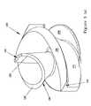
- FIGS. 3( a )– 3 ( e )respectively show isometric, top, first side, second side views of an impeller with a continuous vane and a top view of a combined impeller and wear plate in accord with the present concepts.
- FIGS. 4( a )–( b )show a top view and a sectional side view, respectively, of the continuous vane impeller depicted in FIGS. 3( a )– 3 ( d ).
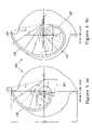
- FIGS. 5( a )–( b )are top-down elevational views of sections of the continuous vane impeller depicted in FIGS. 3( a )– 3 ( d ).
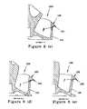
- FIGS. 6( a )– 6 ( f )are, respectively, a top view of the continuous vane impeller depicted in FIGS. 3( a )– 3 ( d ), showing sectional lines taken along sections E—E, F—F, G—G, and H—H, the cross-sectional views taken along such sections, and an enlarged cross-section of a portion of the view of FIG. 6( c ) shown in combination with a wear plate.
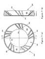
- FIGS. 7( a )– 7 ( b )are, respectively, a top view and a side cross-sectional view of a notched wear plate in accord with the present examples.
- FIG. 8( a )is a top view of a combination of the impeller of FIGS. 3( a )– 3 ( d ) and the wear plate of FIG. 7( a ), showing sectional lines taken along sections J—J through S—S, as shown, and FIGS. 8( b )–( d ) are isometric, first side and second side views of a combination of the impeller of FIGS. 3( a )– 3 ( d ) and the wear plate of FIG. 7( a ).
- FIGS. 9( a )– 9 ( h )show sectional views taken along sections J—J through S—S, as shown in FIG. 8( a ).
- FIG. 3( a )shows an isometric view of an impeller 100 with a continuous vane 110 in accord with the concepts described herein.
- the leading edge 120 of impeller 100extends into and through an eye of a corresponding wear plate, an exemplary wear plate 200 being shown for example in FIG. 7( a ), and extends outwardly therefrom, as shown for example in FIGS. 8( a )–( d ).
- the top 101 of the impeller 100may be advantageously slightly truncated or flattened without adversely impacting the pumping or trash handling characteristics of the pump, such as shown in FIGS. 3( a )–( d ), to provide, for example, a good reference point for measuring dimensions and placement of the impeller 100 during the machining thereof.
- the continuous vane 110 configurationeliminates the conventional centrifugal pump impeller central hub and correspondingly eliminates clogging of the pump impeller 100 due to retention of flexible solids, such as strings, ropes, rags, plastic bags, and the like, on such impeller hub.
- flexible solidssuch as strings, ropes, rags, plastic bags, and the like
- the rotation of the impellergenerates centrifugal forces at the leading edge which helps dislodge flexible solids hanging over the leading edge of the impeller vane, forcing such flexible solids into the liquid flow path.
- Flexible solids which are not dislodged by the aforementioned centrifugal forcesare carried down the slope of the leading edge by the fluid axial flow velocity to encounter the wear plate inner diameter.
- one or more notches and/or recessesare provided in the wear plate, such as at the inner diameter of the wear plate, to dislodge flexible solids on the impeller vane leading edge into the liquid flow path.
- the impeller to wear plate interfaceis the region in which the top portion of an impeller vane (e.g., 110 ) is adjacent (or would be adjacent) to a corresponding wear plate 200 inner or wear surface 201 (see, e.g., FIGS. 9( a )–( h )).
- FIG. 3( e )A top-down view of the impeller to wear plate interface for one static position of the impeller vane 110 is shown by way of example in FIG. 3( e ), wherein the interface is represented by the shaded portion I 1 .
- the impeller to wear plate interfacewould be radially bounded, from the perspective of a 2-D top-down view, by a ring-shaped section I IWP having an outer radius OR I defined by the distal tip 123 of the impeller vane on the outer side and an inner radius IR W of the wear plate 200 on the inner side.
- the beginning or proximal end of the impeller to wear plate interface I IWPis shown to occur at the point represented by reference numeral 122 , which depicts the intersection, in the top-down view, between an inner radius IR W of the wear plate 200 and the vane 110 .
- Solids which become lodged on the vane 110 at or adjacent the impeller to wear plate interface I IWPthen heat up, de-water, or pack, causing a build up on the vane, increased impeller drag, and reduced efficiency, and may cause pump seizure or prevent a pump from starting once it is stopped.
- a flange or winglet 130provided on the impeller vane (e.g., 110 ) so as to widen the top surface of the impeller vane over at least a portion of the impeller to wear plate interface I IWP , the region in which the top portion of impeller vane 110 is adjacent (or would be adjacent) to a corresponding wear plate 200 inner or wear surface 201 , as noted above.
- the topmost portion of the impeller vane 110 opposing wear plate 200 wear surface 201is the working surface 125 of the vane.
- the working surface 125may consist of only a conventional vane top surface (i.e., no widening of the vane at a top portion thereof) or may comprise, in accord with the present aspects, a vane top surface having integrated therewith a flange or winglet portion 130 , such as shown in FIG. 3( a ), to increase the area of the working surface.
- Flange 130may be provided not only on continuous vanes 110 , such as depicted in FIGS. 3( a )– 3 ( d ), but may also be provided on conventional, non-continuous vanes.
- the transition between the leading edge 120 and the working surface 125occurs at the opening/eye or inner diameter (ID) of the wear plate or, in other words, the proximal end of the impeller to wear plate interface I IWP represented by reference numeral 122 .
- Working surface 125is the portion of the impeller vane 110 disposed (or to be disposed) opposite a wear plate 200 wear surface 201 .
- the working surface 125comprises one-half (e.g., a lower half) of the impeller to wear plate interface I IWP
- the portion of the wear plate wear surface 201 disposed opposite to the working surfacecomprises the other one-half (e.g., an upper half) of the impeller to wear plate interface.
- the leading edge 120 of the vane 110has, at least in a vicinity of a top/central portion 101 or midpoint of the impeller 100 , a substantially constant thickness both at the midpoint and on either side thereof, reflective of a hub-less design in accord with one aspect of the present concepts.
- Vane 110which is optionally symmetric, is formed such that a height of top surfaces of the vane (whether it be leading edge 120 portion, working portion 125 , or flange portion 130 ) relative to a bottom of impeller 100 increases continuously between an outer radius OR I and a top/central region 101 of the impeller, which may be slightly truncated.
- the height at the absolute center of the vanemay be equal to the height at points on the leading edge 120 adjacent, such as shown in FIG. 4( b ). Therefore, the top portion or central region 101 , would in one aspect encompass points on the leading edge 120 having, measured from the center of the impeller 100 or vane 110 , a radius less than about 1 ⁇ 3 that of the outer radius of the leading edge, and still more preferably, a radius less than about 1 ⁇ 4 that of the outer radius of the leading edge.
- Widening of the top surface of the impeller vane 110 over at least a portion of the impeller to wear plate interface I IWPreduces the apparent differential pressure across the face of the vane and, accordingly, decreases the amount of fluid and/or solid migration to the lower pressure side of the vane.
- This reduction in the apparent differential pressureis particularly beneficial in configurations wherein the clearance between the impeller vane 110 and the wear plate 200 is close, such as a range of between about 0.005 –0.050 inches and more particularly between about 0.010–0.025 inches, useful in centrifugal pumps, which are required to generate and maintain high differential pressures.
- Widening of the vane 110 along the impeller to wear plate interface I IWPalso increases the distance that any re-circulation has to travel across the face of the impeller vane, thus improving energy efficiency, solids migration, and improving wear characteristics. Widening of the vane 110 along impeller to wear plate interface I IWP further restricts or limits a direct flow path or bleed through from one side of the vane to the other side of the vane, an advantage that is particularly beneficial when such impeller 100 is used in combination with a pump wear plate provided with flow interrupters 210 , as described with respect to the example of FIG. 7( a ).
- the vane 110includes a flange 130 provided along and forming a part of the vane working surface 125 .
- Flange 130starts increasing in width at or near the proximal end 122 of the impeller to wear plate interface I IWP and progressively increases in width along the vane in the direction of the distal end 123 of the impeller to wear plate interface over substantially an entire length of the vane.
- Flange 130may advantageously narrow toward a distal or outlet end of the vane.
- Flange 130may be formed so as to rapidly or gradually achieve a constant width or to gradually increase in width over only a portion of the vane working surface 125 .
- the present conceptsencompass any widened working surface 125 , no matter what the geometry, including but not limited to an continuous or intermittent widening.
- FIGS. 4( a )–( b )show a top view and a sectional side view, respectively, of a continuous vane impeller 100 such as depicted in FIGS. 3( a )–( d ).
- the impeller 100 continuous vane 110has an overall diameter of 13.57 inches, as measured from one distal tip of the vane to the other distal tip of the vane on the opposite end of the impeller.
- FIG. 4( b )represents a cross-sectional view U—U taken along line U—U in FIG. 4( a ).
- the overall profile of the continuous vane 110 in FIG. 4( b ), comprising the truncated top/central portion 101has an overall height of about 8.169 inches having, at a top portion thereof, a truncated conic section defining an angle between the side and the axis of rotation of about 48°. Dashed lines depict the conic section that would be traced by the leading edge 120 and the working surface 125 (comprising flange 130 ) during rotation of the impeller.
- Reference numeral 122approximates a location of the beginning or proximal end of the impeller to wear plate interface I IWP at the intersection between an inner radius of vane 110 and a wear plate associated therewith. Reference numeral 122 thus denotes the transition between the vane leading edge 120 and the vane working surface 125 , which comprises flange 130 .
- FIGS. 5( a )–( b )are top-down elevational views of sections of the continuous vane impeller 100 depicted in FIG. 3 .
- FIG. 5( a )is a top-down view of the bottom of one-half of the continuous vane 110 where the vane meets the back supporting shroud 105 .
- FIG. 5( b )is a top-down view of the top or leading edge 120 and working surfaces 125 of the same one-half of the continuous vane shown in FIG. 5( a ) with the flange portion 130 removed for clarity.
- the vane curvaturemay be generally defined as a log spiral or a near log spiral, but is certainly not limited thereto.
- FIG. 5( a )shows that the curve followed by the vane 110 bottom follows a progressively smaller radius of curvature toward an inner radius of the vane, wherein a distal or outlet end of the vane is defined by a curved section having a radius of 7.01 inches, a center of the radius being taken at a position, as shown.
- the bottom of the vane 110is further defined by, in the depicted example, a second middle curved section having a radius of 4.17 inches at a center point displaced 1.87 inches along a y-axis and 0.43 inches along a x-axis, and second middle curved section having a radius of 2.87 inches at a center point displaced 1.58 inches along a y-axis and ⁇ 0.84 inches along the x-axis, and a proximal section having a radius of 0.35 inches, as shown.
- FIG. 5( b )shows that the curve followed by the vane 110 also follows a progressively smaller radius of curvature between the distal or outlet end of the vane and the proximal or center portion of the vane.
- the distal end of vane 110is defined by a curved section having a radius of 7.01 inches, a center of the radius being taken at a position, as shown, that is the same as that for the vane 110 bottom.
- Vane 110is further defined by, in the depicted example, a fourth middle curved section also having a radius of 7.62 inches at a center point displaced 0.13 inches along a y-axis and slightly outwardly from the initial center radius point along the x-axis.
- a third vane portionis defined by an arc having a radius of 4.94 inches at a center point displaced 0.20 inches along a y-axis and 0.58 inches along the x-axis.
- a second middle curved sectionhaving a radius of 4.25 inches at a center point displaced ⁇ 0.02 inches along a y-axis and ⁇ 0.06 inches along the x-axis
- a first middle curved sectionhaving a radius of 2.41 inches at a center point displaced ⁇ 1.72 inches along a y-axis and ⁇ 0.77 inches along the x-axis
- a proximal sectionhaving a radius of 1.72 inches at a center point displaced ⁇ 1.89 inches along a y-axis and ⁇ 0.11 inches along the x-axis.
- the geometry of the example depicted in FIGS. 5( a )–( b )is only one example of a continuous vane in accord with the present concepts and the concepts expressed herein are not limited thereby
- FIG. 6( a )is a top-down view of a portion of impeller 100 showing sections E—E, F—F, G—G, and H—H, depicted in FIGS. 6( b )– 6 ( e ).
- Cross-section E—Eis taken at an outlet of the impeller and cross-sections F—F, G—G, and H—H are taken at progressively inward locations in the impeller.
- FIG. 6( b )– 6 ( e )shows a flange portion 130 , of varying degrees, depending from the vane 110 and comprising a portion of the working surface 125 .
- a front face of the working surface 125which includes flange 130 , angled away from the impeller 100 axis of rotation in a direction of flow at an angle ⁇ F substantially equal to if not equal to an angle ⁇ W of an opposing wear plate 200 .
- the correspondence between ⁇ F and ⁇ Wmaintains a clearance between the opposing surfaces of the wear plate and impeller vane 110 of, between about 0.005–0.050 inches and, more preferably, between 0.010–0.025 inches, in accord with the concepts herein.
- the wear surface 201 defined by the wear plate 200is substantially linear along a longitudinal axis thereof, such as a wear surface defined by a conic section or a wear surface in the shape of a plate, then ⁇ F and ⁇ W are substantially constant over respective longitudinal axes thereof. If the wear surface defined by the wear plate 200 is curved, such as a wear surface defined by a curvilinear solid of revolution formed by revolving an area bounded by a curve around a center axis of the wear plate, then ⁇ F and ⁇ W will vary together accordingly.
- the wear surfaceis not limited to a single form and may comprise at least one of a substantially flat surface, a truncated conic section, and a curvilinear solid of revolution formed by revolving an area bounded by a curve around a center axis of the wear plate.
- the angle ⁇ F of the vane working surface 125 and/or front face of the flange 130is fixed to the angle ⁇ W of the wear plate 200 wear surface 201 in opposition thereto to maintain a narrow gap therebetween
- the angle ⁇ between the side working surfaces 126 of the vane 110 and the rear face of flange 130is independently variable.
- the angle ⁇ in the depicted examplemay be thought of as the angle defined between a first line parallel to the vane along the axis of rotation of the impeller and a line second drawn tangent to a point of inflection of the underside of flange 130 where the curvature changes from convex to concave to intersect the first line (i.e., the origin).
- the underside of the flangemay present a substantially planar surface (e.g., a chamfered bottom surface or a curved surface having a substantially flat portion) from which an extension thereto may be used to define one extent of angle ⁇ .
- the angle ⁇is slightly greater than 90° in FIG. 6( c ), about 90° in FIG. 6( d ), and slightly less than 90° in FIG. 6( e ).
- Angle ⁇may be uniform over a whole or a part of the length of the vane 110 or may vary over a length of the vane.
- Angle ⁇which would represent a chamfered or angled surface, is advantageously softened by providing the intersection between the side working surfaces 126 of the vane 110 and the rear face of flange 130 with a curvilinear profile.
- This curved profilemay include, but is not limited to, a substantially constant radius, a radius that increases over at least an end portion thereof, or a radius that flares outwardly over an end portion thereof.
- the curvature of the rear face of flange 130is provided to influence the flow of solids away from the impeller to wear plate interface I IWP .
- the curved rear face of flange 130will change the direction of solids that are moving in a direction toward the impeller to wear plate interface I IWP away from the impeller to wear plate interface.
- This change in directionmay be slight (e.g., about 1°), moderate (e.g., about 90°), or significant (e.g., about 180°), which corresponds to an angle ⁇ of about 179°, 90°, and 0°, respectively, as defined.
- the angle ⁇may range from 180° to 0°, inclusive.
- angle ⁇would range from about 130°–50°, and still more preferably from 110°–70°.
- the wear plate 200 in accord with the present conceptsis provided with a flow interrupter 210 , which may take the form of one or more recesses or notches.
- the term notchis used herein to refer to an opening in the wear plate 200 and/or wear plate wear surface 201 , the opening being defined by any geometric shape and extending through a thickness of the wear plate and/or the wear plate wear surface in at least a portion of the opening, whereas the term recess is used herein to refer to an opening in the wear plate 200 and/or wear plate wear surface 201 , the opening being defined by any geometric shape, which does not extend through a thickness of the wear plate and/or the wear plate wear surface over any portion of the opening.
- the walls of the flow interrupter(s) 210may comprise sidewalls that are vertical or perpendicular to the surface of the wear plate 200 or wear plate wear surface 201 , or may comprise sidewalls that are angled or curved relative thereto.
- the flow interrupter 210interrupts migration of solids between the impeller 100 and the wear plate 200 along the impeller to wear plate interface I IWP .
- Many solids found in waste water, such as plastic products, and vegetationhave a tendency to de-water.
- de-watered solidscreate drag on the driver, but usually allow the pump to keep turning, albeit with diminished performance.
- the de-watered solidscan act like a brake and prevent the pump from starting.
- the flow interrupter 210serves to keep the vanes clean during pumping so as to maintain not only a high efficiency, but to enable faster restart.
- a wear plate 200 suitable for use in combination with a centrifugal pump and impeller 100includes a wear surface 201 that forms one side of the impeller to wear plate interface I IWP .
- This wear surface 201may advantageously be defined by a conic section, such as shown in FIG. 7( b ) and, more particularly, FIGS. 9( a )–( h ).
- the wear surface 201may be defined by a curvilinear solid of revolution formed by revolving an area bounded by a curve around a center axis of the wear plate 200 or even by a flat surface (i.e., a flat wear plate, such as used in smaller pumps).
- At least one flow interrupter 210in the form of one or more notches and/or recesses in the example depicted in FIGS. 7( a )–( b ), are provided in the wear plate 200 so as to extend along the wear plate wear surface 201 a first direction perpendicular to predetermined direction of an rotation of impeller 100 and/or a second direction crossing against a direction of rotation of the impeller.
- the second directionranges from the first direction up to and including a direction opposite the direction of rotation.
- the first directionwould consist of a perpendicular thereto such as represented by the hands of a clock face centered about the clock hand axis of rotation.
- the second directionwould include any direction between such perpendicular which crosses at some angle against a direction of rotation of the impeller 100 and a direction opposite to (e.g., counter-clockwise) the direction of impeller rotation.
- flow interrupter(s) 210are not provided in a direction of rotation of impeller 100 , but rather in a direction against the rotation of the impeller or perpendicular thereto.
- a single oblong flow interrupter 210such as a notch or recess, is disposed to extend in the first and/or second direction, noted above, along a longitudinal direction (e.g., front to back or, in the cross-sectional side view of FIG. 7( b ), from bottom to top) of the wear plate 200 between an inner radius IR W of the wear plate and an outer radius OR W and, optionally, from an inner radius of the wear plate to an outer radius of the wear plate.
- the length of the notch or recess 210is denoted as “L”.
- a plurality of (i.e., two or more) notches and/or recesses 210may be provided to extend along a longitudinal direction (e.g., front-to-back) of the wear plate 200 wear surface 201 in one or both of the aforementioned first and second directions between an inner radius r I of the wear plate and an outer radius r O .
- the notches and/or recesses 210may be of uniform length and/or shape or may comprise dissimilar lengths and/or shapes.
- a short notchmay be provided along the first direction or second direction near the inner radius of the wear plate in combination with a long recess formed adjacent the short notch, the long recess extending from such point adjacent the short notch to the wear plate outer radius.
- a plurality of alternating notches and recesses 210may be provided.
- the notches and/or recesses 210may be spaced apart along the first and/or second direction noted above, or may be spaced along a common diameter of the wear surface 201 , some examples of which are shown in FIG. 7( a ).
- Clusters of notches and/or recesses 210may also be provided.
- one or more notches and/or recesses 210may be provided along a common diameter of the wear plate 200 .
- the notches and/or recesses 210 , or portions thereof,are intersected by the inner radius r I or are otherwise contiguous therewith.
- the notch(es) and/or recess(es) 210are configured to have a length L less than a width of a corresponding impeller vane working surface 125 , whether such working surface consists only of a conventional vane working surface or comprises a widened vane working surface in accord with the present concepts.
- Constraining the length L of the notch(es) and/or recess(es) 210 as noted in this exampleensures that the notch(es) and/or recess(es) are effectively sealed or closed off by the width of the working surface 125 so that a pathway from the high pressure side of the impeller vane 110 to the lower pressure side of the impeller vane is not created by the notch(es) and/or recess(es).
- the notch(es) and/or recess(es) 210may extend along the wear surface 201 a first direction perpendicular to predetermined direction of rotation of impeller 100 , a second direction having a component crossing against a direction of rotation of the impeller (e.g., counter-clockwise), and/or a third direction having a component in a direction of rotation of the impeller (e.g., clockwise).
- bottom surfaces thereofare at a depth of between about 1/32′′–3 ⁇ 8′′ from the wear plate wear surface 201 , and still more preferably between about 1/16′′– 5/16′′ from the wear plate wear surface 201 .
- notches 210may comprise, in a whole or in a part thereof, through-holes extending through the wear surface 201 and/or wear plate 200 .
- the notch(es) and/or recess(es) 210are substantially oval in shape.
- the shape of the flow interrupters 210is not limited to the depicted shapes and other shapes are contemplated as being within the scope of the concepts expressed herein including but not limited to a square, rectangle, circle, oval or any oblong form.
- the wear plate 200may comprise a plurality of circular notch(es) and/or semi-spherical recess(es) along a wear surface 201 of the wear plate facing the impeller 100 in at least one of the aforementioned first, second, and/or third directions, as applicable to the particular aspect.
- FIGS. 8( a )– 8 ( d )are top, isometric, first side and second side views of a combination of the impeller of FIGS. 3( a )– 3 ( d ) and the wear plate of FIGS. 7( a )–( b ).
- FIGS. 8( a )– 8 ( d )show the spatial relation between the impeller 100 and the wear plate 200 during operation of a centrifugal pump employing the combination.
- FIG. 8( a )shows the radial extent of the impeller to wear plate interface Ilwp, which begins at the aforementioned proximal end 122 , wherein the vane 110 intersects the inner radius IR w of the wear plate 200 , and extends outwardly to the distal end 123 of the vane, wherein the vane opposition to the wear plate terminates.
- Sections J—J, K—K, L—L, M—M, N—N, P—P, R—R, and S—S, of FIG. 8( a )are shown in FIGS. 9( a )– 9 ( h ) and are further described below.
- FIGS. 9( a )– 9 ( h )show cross-sections of a wear plate 200 having an inner wear surface 201 that is conical.
- the working surfaces 125 of vane 110which comprise a front face of flange 130 , are provided with an inclination or angle equal to that of wear plate 200 wear surface 201 to form an operational clearance (e.g., between about 0.005′′–0.025′′) therebetween along the entirety of the respective vane wear surface and flange working surfaces so as to permit effective operation of a centrifugal pump into which the depicted combination is disposed.
- Various flow interrupters 210are shown in the wear plate 200 . In particular, FIG.
- FIG. 9( b )shows a flow interrupter 210 having a dimension in cross-section which is less than a corresponding dimension of the impeller working surface 125 .
- the impeller working surface 125blocks a path through the flow interrupter 210 from the higher pressure (right) side of the impeller vane 110 to the lower pressure (left) side of the vane.
- a continuous vane in accord with the present conceptsmay be coupled with a conventional wear plate.
- a wear plate in accord with the present conceptsmay be coupled with a conventional impeller vane.
- a flange in accord with the present conceptscould be provided on a conventional vane in combination with a conventional wear plate.
Landscapes
- Engineering & Computer Science (AREA)
- Mechanical Engineering (AREA)
- General Engineering & Computer Science (AREA)
- Physics & Mathematics (AREA)
- Geometry (AREA)
- Structures Of Non-Positive Displacement Pumps (AREA)
Abstract
Description
Claims (50)
Priority Applications (6)
| Application Number | Priority Date | Filing Date | Title |
|---|---|---|---|
| US10/697,162US7037069B2 (en) | 2003-10-31 | 2003-10-31 | Impeller and wear plate |
| CA2543970ACA2543970C (en) | 2003-10-31 | 2004-10-13 | Improved impeller and wear plate |
| AU2004287048AAU2004287048A1 (en) | 2003-10-31 | 2004-10-13 | Improved impeller and wear plate |
| EP04794763AEP1692400A2 (en) | 2003-10-31 | 2004-10-13 | Improved impeller and wear plate |
| PCT/US2004/033494WO2005045254A2 (en) | 2003-10-31 | 2004-10-13 | Improved impeller and wear plate |
| ZA200604164AZA200604164B (en) | 2003-10-31 | 2006-05-24 | Improved impeller and wear plate |
Applications Claiming Priority (1)
| Application Number | Priority Date | Filing Date | Title |
|---|---|---|---|
| US10/697,162US7037069B2 (en) | 2003-10-31 | 2003-10-31 | Impeller and wear plate |
Publications (2)
| Publication Number | Publication Date |
|---|---|
| US20050095124A1 US20050095124A1 (en) | 2005-05-05 |
| US7037069B2true US7037069B2 (en) | 2006-05-02 |
Family
ID=34550290
Family Applications (1)
| Application Number | Title | Priority Date | Filing Date |
|---|---|---|---|
| US10/697,162Expired - LifetimeUS7037069B2 (en) | 2003-10-31 | 2003-10-31 | Impeller and wear plate |
Country Status (6)
| Country | Link |
|---|---|
| US (1) | US7037069B2 (en) |
| EP (1) | EP1692400A2 (en) |
| AU (1) | AU2004287048A1 (en) |
| CA (1) | CA2543970C (en) |
| WO (1) | WO2005045254A2 (en) |
| ZA (1) | ZA200604164B (en) |
Cited By (40)
| Publication number | Priority date | Publication date | Assignee | Title |
|---|---|---|---|---|
| WO2009032299A1 (en)* | 2007-09-04 | 2009-03-12 | Envirotech Pumpsystems, Inc. | Wear plate for a centrifugal pump |
| US20090290979A1 (en)* | 2008-05-23 | 2009-11-26 | Mitsubishi Heavy Industries, Ltd. | Compressor housing |
| US20100296921A1 (en)* | 2008-11-26 | 2010-11-25 | Cottrell Matthew A | Socket with Bearing Bore and Integrated Wear Plate |
| US20110056707A1 (en)* | 2009-09-08 | 2011-03-10 | Jonathan Gamble | Fire-Extinguishing System and Method for Operating Servo Motor-Driven Foam Pump |
| US20110056708A1 (en)* | 2009-09-08 | 2011-03-10 | Jonathan Gamble | Fire-Extinguishing System with Servo Motor-Driven Foam Pump |
| US20110057595A1 (en)* | 2009-09-08 | 2011-03-10 | Ron Flanary | Method of Controlling a Motor |
| WO2011086382A1 (en) | 2010-01-16 | 2011-07-21 | Nanoridge Materials, Incorporated | Ceramic matrix composite articles comprising graphene nanoribbons - like material and their manufacturing method using carbon nanotubes |
| US20110236210A1 (en)* | 2004-09-17 | 2011-09-29 | The Penn State Research Foundation | Expandable impeller pump |
| US8183810B2 (en) | 2009-09-08 | 2012-05-22 | Hoffman Enclosures, Inc. | Method of operating a motor |
| US8485961B2 (en) | 2011-01-05 | 2013-07-16 | Thoratec Corporation | Impeller housing for percutaneous heart pump |
| US8535211B2 (en) | 2009-07-01 | 2013-09-17 | Thoratec Corporation | Blood pump with expandable cannula |
| US20130243634A1 (en)* | 2010-11-24 | 2013-09-19 | Frideco Ag C/O Hidrotlal Ag | Self-Cleaning Screw-Type Centrifugal Wheel Pump with Recirculation Behind the Impeller |
| US8591393B2 (en) | 2011-01-06 | 2013-11-26 | Thoratec Corporation | Catheter pump |
| US8597170B2 (en) | 2011-01-05 | 2013-12-03 | Thoratec Corporation | Catheter pump |
| US8721517B2 (en) | 2012-05-14 | 2014-05-13 | Thoratec Corporation | Impeller for catheter pump |
| US9138518B2 (en) | 2011-01-06 | 2015-09-22 | Thoratec Corporation | Percutaneous heart pump |
| US9308302B2 (en) | 2013-03-15 | 2016-04-12 | Thoratec Corporation | Catheter pump assembly including a stator |
| US9327067B2 (en) | 2012-05-14 | 2016-05-03 | Thoratec Corporation | Impeller for catheter pump |
| US9358329B2 (en) | 2012-07-03 | 2016-06-07 | Thoratec Corporation | Catheter pump |
| US9364592B2 (en) | 2004-09-17 | 2016-06-14 | The Penn State Research Foundation | Heart assist device with expandable impeller pump |
| US9381288B2 (en) | 2013-03-13 | 2016-07-05 | Thoratec Corporation | Fluid handling system |
| US9421311B2 (en) | 2012-07-03 | 2016-08-23 | Thoratec Corporation | Motor assembly for catheter pump |
| US9446179B2 (en) | 2012-05-14 | 2016-09-20 | Thoratec Corporation | Distal bearing support |
| US9675738B2 (en) | 2015-01-22 | 2017-06-13 | Tc1 Llc | Attachment mechanisms for motor of catheter pump |
| US9675739B2 (en) | 2015-01-22 | 2017-06-13 | Tc1 Llc | Motor assembly with heat exchanger for catheter pump |
| US9770543B2 (en) | 2015-01-22 | 2017-09-26 | Tc1 Llc | Reduced rotational mass motor assembly for catheter pump |
| US9827356B2 (en) | 2014-04-15 | 2017-11-28 | Tc1 Llc | Catheter pump with access ports |
| US9872947B2 (en) | 2012-05-14 | 2018-01-23 | Tc1 Llc | Sheath system for catheter pump |
| US9907890B2 (en) | 2015-04-16 | 2018-03-06 | Tc1 Llc | Catheter pump with positioning brace |
| US10029037B2 (en) | 2014-04-15 | 2018-07-24 | Tc1 Llc | Sensors for catheter pumps |
| US10105475B2 (en) | 2014-04-15 | 2018-10-23 | Tc1 Llc | Catheter pump introducer systems and methods |
| US10583232B2 (en) | 2014-04-15 | 2020-03-10 | Tc1 Llc | Catheter pump with off-set motor position |
| US11077294B2 (en) | 2013-03-13 | 2021-08-03 | Tc1 Llc | Sheath assembly for catheter pump |
| US11219756B2 (en) | 2012-07-03 | 2022-01-11 | Tc1 Llc | Motor assembly for catheter pump |
| US11229786B2 (en) | 2012-05-14 | 2022-01-25 | Tc1 Llc | Impeller for catheter pump |
| US11248619B2 (en)* | 2016-01-27 | 2022-02-15 | John A. Kozel | Construction of articles of manufacture of fiber reinforced structural composites |
| EP3971422A1 (en) | 2020-09-22 | 2022-03-23 | Xylem Europe GmbH | Open impeller for submergible pump configured for pumping liquid comprising abrasive matter and submergible pump therewith |
| US11339804B2 (en) | 2018-08-01 | 2022-05-24 | Liberty Pumps, Inc. | Self-cleaning pump |
| US11850414B2 (en) | 2013-03-13 | 2023-12-26 | Tc1 Llc | Fluid handling system |
| US12350483B2 (en) | 2016-07-21 | 2025-07-08 | Tc1 Llc | Fluid seals for catheter pump motor assembly |
Families Citing this family (22)
| Publication number | Priority date | Publication date | Assignee | Title |
|---|---|---|---|---|
| US6889082B2 (en)* | 1997-10-09 | 2005-05-03 | Orqis Medical Corporation | Implantable heart assist system and method of applying same |
| US7416525B2 (en) | 2003-09-18 | 2008-08-26 | Myrakelle, Llc | Rotary blood pump |
| WO2006133577A1 (en)* | 2005-06-16 | 2006-12-21 | Egger Pumps Technology Ag | Centrifugal pump |
| US20070036643A1 (en)* | 2005-08-10 | 2007-02-15 | Envirotech Pumpsystems, Inc. | Tool-free adjustable clean out assembly for a pump |
| KR20090074110A (en) | 2006-03-31 | 2009-07-06 | 오퀴스 메디컬 코포레이션 | Rotary Blood Pump |
| US8414257B2 (en)* | 2006-09-21 | 2013-04-09 | The Gorman-Rupp Co. | Self-priming centrifugal pump |
| US8066477B2 (en) | 2009-03-02 | 2011-11-29 | Dalmatian Hunter Holdings Ltd. | Staged centrifugal pump apparatus for pumping a viscous fluid |
| NL2005810C2 (en)* | 2010-12-03 | 2012-06-05 | Ihc Syst Bv | Centrifugal pump and a double bent rotor blade for use in such a centrifugal pump. |
| DE102011007907B3 (en)* | 2011-04-21 | 2012-06-21 | Ksb Aktiengesellschaft | Impeller for centrifugal pumps |
| JP6347747B2 (en)* | 2012-11-08 | 2018-06-27 | 新明和工業株式会社 | Centrifugal pump |
| DE102012023731B4 (en)* | 2012-12-05 | 2021-03-11 | Wilo Se | Centrifugal pump especially for waste water or dirty water |
| EP4190376A1 (en) | 2013-03-15 | 2023-06-07 | Tc1 Llc | Catheter pump assembly including a stator |
| DK2908012T3 (en)* | 2014-01-24 | 2019-04-01 | Mcfinn Tech | Radial impeller and centrifugal pump housing |
| EP3583973A1 (en) | 2014-08-18 | 2019-12-25 | Tc1 Llc | Guide features for percutaneous catheter pump |
| CA2863373C (en)* | 2014-09-12 | 2015-12-22 | Dalmatian Hunter Holdings Ltd. | Submersible disk-type pump for viscous and solids-laden fluids having helical inducer |
| WO2016089820A1 (en)* | 2014-12-04 | 2016-06-09 | Exxonmobil Upstream Research Company | Additive manufacturing to increase/modify equipment operating conditions |
| JP6488167B2 (en)* | 2015-03-27 | 2019-03-20 | 株式会社荏原製作所 | Centrifugal pump |
| CN105927595A (en)* | 2016-06-28 | 2016-09-07 | 广州市拓道流体设备技术有限公司 | Cavitation prevention slurry pump |
| EP3808401A1 (en) | 2016-07-21 | 2021-04-21 | Tc1 Llc | Gas-filled chamber for catheter pump motor assembly |
| CN110143408B (en)* | 2019-06-20 | 2024-05-31 | 江苏徐工工程机械研究院有限公司 | Throwing device and material throwing machine |
| CN110425178A (en)* | 2019-06-27 | 2019-11-08 | 山西天海给排水设备有限公司 | A kind of algorithm for design of the geometric parameter of efficient non-plugging inside Impeller in Screw Centrifugal Pump |
| CN119594048A (en)* | 2024-12-24 | 2025-03-11 | 湖北三峰透平装备股份有限公司 | Anticorrosive wear-resisting waste gas fan |
Citations (29)
| Publication number | Priority date | Publication date | Assignee | Title |
|---|---|---|---|---|
| US1735754A (en) | 1927-07-22 | 1929-11-12 | Frederick Iron & Steel Company | Liner for centrifugal pumps |
| US2245035A (en) | 1939-02-13 | 1941-06-10 | American Well Works | Centrifugal sludge pump |
| US3447475A (en) | 1967-01-09 | 1969-06-03 | Albert Blum | Centrifugal pump |
| US3984193A (en)* | 1974-10-07 | 1976-10-05 | General Motors Corporation | Radial-flow turbomachine |
| US4052133A (en) | 1975-11-12 | 1977-10-04 | The Gorman-Rupp Company | Corrosion and abrasion resistant centrifugal pump |
| US4145008A (en) | 1977-08-22 | 1979-03-20 | The Gorman-Rupp Company | Waste material pumping apparatus |
| US4342538A (en) | 1980-06-02 | 1982-08-03 | The Gorman-Rupp Company | Face-type shaft seal |
| US4427336A (en) | 1978-11-17 | 1984-01-24 | Lake Geoffrey G | Single vane rotodynamic impeller |
| US4527948A (en) | 1982-11-03 | 1985-07-09 | Giw Industries, Inc. | Pump adjustment assembly |
| US4540528A (en) | 1980-07-08 | 1985-09-10 | Haegeman Johny H | Apparatus for mixing gas and liquid |
| US4575308A (en) | 1983-12-15 | 1986-03-11 | Metal Technologies, Inc. | Solid materials pump |
| US4676718A (en) | 1984-08-16 | 1987-06-30 | Oy E. Sarlin Ab | Impeller for a pump, especially a vortex pump |
| US4758133A (en) | 1986-05-19 | 1988-07-19 | The Gorman-Rupp Company | Pumping system |
| US4904159A (en) | 1988-07-18 | 1990-02-27 | Suburbia Systems, Inc. | Pump impeller |
| US4913619A (en) | 1988-08-08 | 1990-04-03 | Barrett Haentjens & Co. | Centrifugal pump having resistant components |
| US4932837A (en) | 1988-10-21 | 1990-06-12 | Rymal Ted R | Centrifugal pump for liquids |
| US5011370A (en) | 1989-04-27 | 1991-04-30 | Itt Corporation | Centrifugal pump |
| US5240372A (en) | 1992-06-30 | 1993-08-31 | Krienke Heinz H | Centrifugal pumps and systems utilizing same |
| US5256032A (en) | 1992-05-26 | 1993-10-26 | Vaugan Co., Inc. | Centrifugal chopper pump |
| US5516261A (en) | 1993-11-15 | 1996-05-14 | Wilo Gmbh | Unchokable centrifugal pump |
| CA2253067A1 (en) | 1997-11-18 | 1999-05-18 | Itt Manufacturing Enterprises, Inc. | Pump impeller |
| CA2254187A1 (en) | 1997-11-18 | 1999-05-18 | Itt Manufacturing Enterprises, Inc. | Pump impeller |
| CA2256272A1 (en) | 1997-12-18 | 1999-06-18 | Itt Manufacturing Enterprises, Inc. | A pump impeller hub |
| US6042332A (en) | 1997-04-24 | 2000-03-28 | Ksb Aktiengesellschaft | Housing part for a propeller pump |
| US6464454B1 (en) | 1998-06-30 | 2002-10-15 | Abs Pump Production Ab | Centrifugal pump |
| US6468029B2 (en) | 2001-02-21 | 2002-10-22 | George J. Teplanszky | Pump device |
| US6582191B2 (en) | 2001-08-16 | 2003-06-24 | Giw Industries, Inc. | Liner for centrifugal slurry pumps |
| US6599086B2 (en) | 2001-07-03 | 2003-07-29 | Marc S. C. Soja | Adjustable pump wear plate positioning assembly |
| US6799943B2 (en)* | 2000-01-26 | 2004-10-05 | The Gorman-Rupp Company | Centrifugal pump with multiple inlets |
Family Cites Families (6)
| Publication number | Priority date | Publication date | Assignee | Title |
|---|---|---|---|---|
| GB910127A (en)* | 1960-07-18 | 1962-11-07 | James Everett Vaughan | Improvements in or relating to centrifugal non-clogging pumps |
| US3973866A (en)* | 1975-01-02 | 1976-08-10 | Vaughan Co., Inc. | Centrifugal chopping slurry pump |
| US5076757A (en)* | 1981-01-29 | 1991-12-31 | Vaughan Co., Inc. | High head centrifugal slicing slurry pump |
| FI69683C (en)* | 1982-02-08 | 1986-03-10 | Ahlstroem Oy | CENTRIFUGALPUMP FOER VAETSKOR INNEHAOLLANDE FASTA AEMNEN |
| US6156959A (en)* | 1998-04-20 | 2000-12-05 | Universtiy Of Massachusetts | Cactaceae plant and progeny |
| SE524048C2 (en)* | 2002-04-26 | 2004-06-22 | Itt Mfg Enterprises Inc | Device at pump |
- 2003
- 2003-10-31USUS10/697,162patent/US7037069B2/ennot_activeExpired - Lifetime
- 2004
- 2004-10-13CACA2543970Apatent/CA2543970C/ennot_activeExpired - Lifetime
- 2004-10-13WOPCT/US2004/033494patent/WO2005045254A2/enactiveApplication Filing
- 2004-10-13EPEP04794763Apatent/EP1692400A2/ennot_activeWithdrawn
- 2004-10-13AUAU2004287048Apatent/AU2004287048A1/ennot_activeAbandoned
- 2006
- 2006-05-24ZAZA200604164Apatent/ZA200604164B/enunknown
Patent Citations (31)
| Publication number | Priority date | Publication date | Assignee | Title |
|---|---|---|---|---|
| US1735754A (en) | 1927-07-22 | 1929-11-12 | Frederick Iron & Steel Company | Liner for centrifugal pumps |
| US2245035A (en) | 1939-02-13 | 1941-06-10 | American Well Works | Centrifugal sludge pump |
| US3447475A (en) | 1967-01-09 | 1969-06-03 | Albert Blum | Centrifugal pump |
| US3984193A (en)* | 1974-10-07 | 1976-10-05 | General Motors Corporation | Radial-flow turbomachine |
| US4052133A (en) | 1975-11-12 | 1977-10-04 | The Gorman-Rupp Company | Corrosion and abrasion resistant centrifugal pump |
| US4145008A (en) | 1977-08-22 | 1979-03-20 | The Gorman-Rupp Company | Waste material pumping apparatus |
| US4427336A (en) | 1978-11-17 | 1984-01-24 | Lake Geoffrey G | Single vane rotodynamic impeller |
| US4342538A (en) | 1980-06-02 | 1982-08-03 | The Gorman-Rupp Company | Face-type shaft seal |
| US4540528A (en) | 1980-07-08 | 1985-09-10 | Haegeman Johny H | Apparatus for mixing gas and liquid |
| US4527948A (en) | 1982-11-03 | 1985-07-09 | Giw Industries, Inc. | Pump adjustment assembly |
| US4575308A (en) | 1983-12-15 | 1986-03-11 | Metal Technologies, Inc. | Solid materials pump |
| US4676718A (en) | 1984-08-16 | 1987-06-30 | Oy E. Sarlin Ab | Impeller for a pump, especially a vortex pump |
| US4758133A (en) | 1986-05-19 | 1988-07-19 | The Gorman-Rupp Company | Pumping system |
| US4904159A (en) | 1988-07-18 | 1990-02-27 | Suburbia Systems, Inc. | Pump impeller |
| US4913619A (en) | 1988-08-08 | 1990-04-03 | Barrett Haentjens & Co. | Centrifugal pump having resistant components |
| US4932837A (en) | 1988-10-21 | 1990-06-12 | Rymal Ted R | Centrifugal pump for liquids |
| US5011370A (en) | 1989-04-27 | 1991-04-30 | Itt Corporation | Centrifugal pump |
| US5256032A (en) | 1992-05-26 | 1993-10-26 | Vaugan Co., Inc. | Centrifugal chopper pump |
| US5240372A (en) | 1992-06-30 | 1993-08-31 | Krienke Heinz H | Centrifugal pumps and systems utilizing same |
| US5516261A (en) | 1993-11-15 | 1996-05-14 | Wilo Gmbh | Unchokable centrifugal pump |
| US6042332A (en) | 1997-04-24 | 2000-03-28 | Ksb Aktiengesellschaft | Housing part for a propeller pump |
| CA2254187A1 (en) | 1997-11-18 | 1999-05-18 | Itt Manufacturing Enterprises, Inc. | Pump impeller |
| CA2253067A1 (en) | 1997-11-18 | 1999-05-18 | Itt Manufacturing Enterprises, Inc. | Pump impeller |
| US6158959A (en) | 1997-11-18 | 2000-12-12 | Itt Manufacturing Enterprises, Inc. | Pump impeller |
| CA2256272A1 (en) | 1997-12-18 | 1999-06-18 | Itt Manufacturing Enterprises, Inc. | A pump impeller hub |
| US6139260A (en) | 1997-12-18 | 2000-10-31 | Itt Manufacturing Enterprises, Inc. | Pump having a pump housing with one or more feeding grooves |
| US6464454B1 (en) | 1998-06-30 | 2002-10-15 | Abs Pump Production Ab | Centrifugal pump |
| US6799943B2 (en)* | 2000-01-26 | 2004-10-05 | The Gorman-Rupp Company | Centrifugal pump with multiple inlets |
| US6468029B2 (en) | 2001-02-21 | 2002-10-22 | George J. Teplanszky | Pump device |
| US6599086B2 (en) | 2001-07-03 | 2003-07-29 | Marc S. C. Soja | Adjustable pump wear plate positioning assembly |
| US6582191B2 (en) | 2001-08-16 | 2003-06-24 | Giw Industries, Inc. | Liner for centrifugal slurry pumps |
Non-Patent Citations (2)
| Title |
|---|
| T Series (TM) The Best Self-Priming, Solids Handling Trash Pumps Only form Gorman-Rupp. |
| T Series(TM) Self-Priming Centrifugal Pumps, The World Leader in Solids Handling Self-Priming Pumps, pp. 1-12. |
Cited By (95)
| Publication number | Priority date | Publication date | Assignee | Title |
|---|---|---|---|---|
| US20110236210A1 (en)* | 2004-09-17 | 2011-09-29 | The Penn State Research Foundation | Expandable impeller pump |
| US10215187B2 (en) | 2004-09-17 | 2019-02-26 | Tc1 Llc | Expandable impeller pump |
| US9364593B2 (en) | 2004-09-17 | 2016-06-14 | The Penn State Research Foundation | Heart assist device with expandable impeller pump |
| US8376707B2 (en) | 2004-09-17 | 2013-02-19 | Thoratec Corporation | Expandable impeller pump |
| US9364592B2 (en) | 2004-09-17 | 2016-06-14 | The Penn State Research Foundation | Heart assist device with expandable impeller pump |
| US9717833B2 (en) | 2004-09-17 | 2017-08-01 | The Penn State Research Foundation | Heart assist device with expandable impeller pump |
| US11434921B2 (en) | 2004-09-17 | 2022-09-06 | Tc1 Llc | Expandable impeller pump |
| US8992163B2 (en) | 2004-09-17 | 2015-03-31 | Thoratec Corporation | Expandable impeller pump |
| US11428236B2 (en) | 2004-09-17 | 2022-08-30 | Tc1 Llc | Expandable impeller pump |
| US11708833B2 (en) | 2006-03-23 | 2023-07-25 | The Penn State Research Foundation | Heart assist device with expandable impeller pump |
| US12404858B2 (en) | 2006-03-23 | 2025-09-02 | The Penn State Research Foundation | Catheter blood pump heart assist device |
| US10864309B2 (en) | 2006-03-23 | 2020-12-15 | The Penn State Research Foundation | Heart assist device with expandable impeller pump |
| US10149932B2 (en) | 2006-03-23 | 2018-12-11 | The Penn State Research Foundation | Heart assist device with expandable impeller pump |
| AU2008296843B2 (en)* | 2007-09-04 | 2011-08-18 | Envirotech Pumpsystems, Inc. | Wear plate for a centrifugal pump |
| WO2009032299A1 (en)* | 2007-09-04 | 2009-03-12 | Envirotech Pumpsystems, Inc. | Wear plate for a centrifugal pump |
| US20090232639A1 (en)* | 2007-09-04 | 2009-09-17 | Arnold Kim M | Wear plate for a centrifugal pump |
| US8251650B2 (en)* | 2008-05-23 | 2012-08-28 | Mitsubishi Heavy Industries, Ltd. | Compressor housing |
| US20090290979A1 (en)* | 2008-05-23 | 2009-11-26 | Mitsubishi Heavy Industries, Ltd. | Compressor housing |
| US20100296921A1 (en)* | 2008-11-26 | 2010-11-25 | Cottrell Matthew A | Socket with Bearing Bore and Integrated Wear Plate |
| US8454307B2 (en) | 2008-11-26 | 2013-06-04 | Sta-Rite Industries, Llc | Socket with bearing bore and integrated wear plate |
| US8684904B2 (en) | 2009-07-01 | 2014-04-01 | Thoratec Corporation | Blood pump with expandable cannula |
| US8535211B2 (en) | 2009-07-01 | 2013-09-17 | Thoratec Corporation | Blood pump with expandable cannula |
| US8297369B2 (en) | 2009-09-08 | 2012-10-30 | Sta-Rite Industries, Llc | Fire-extinguishing system with servo motor-driven foam pump |
| US8183810B2 (en) | 2009-09-08 | 2012-05-22 | Hoffman Enclosures, Inc. | Method of operating a motor |
| US8164293B2 (en) | 2009-09-08 | 2012-04-24 | Hoffman Enclosures, Inc. | Method of controlling a motor |
| US20110057595A1 (en)* | 2009-09-08 | 2011-03-10 | Ron Flanary | Method of Controlling a Motor |
| US20110056708A1 (en)* | 2009-09-08 | 2011-03-10 | Jonathan Gamble | Fire-Extinguishing System with Servo Motor-Driven Foam Pump |
| US20110056707A1 (en)* | 2009-09-08 | 2011-03-10 | Jonathan Gamble | Fire-Extinguishing System and Method for Operating Servo Motor-Driven Foam Pump |
| WO2011086382A1 (en) | 2010-01-16 | 2011-07-21 | Nanoridge Materials, Incorporated | Ceramic matrix composite articles comprising graphene nanoribbons - like material and their manufacturing method using carbon nanotubes |
| US9709071B2 (en)* | 2010-11-24 | 2017-07-18 | Frideco Ag | Self-cleaning screw-type centrifugal wheel pump with recirculation behind the impeller |
| US20130243634A1 (en)* | 2010-11-24 | 2013-09-19 | Frideco Ag C/O Hidrotlal Ag | Self-Cleaning Screw-Type Centrifugal Wheel Pump with Recirculation Behind the Impeller |
| US8597170B2 (en) | 2011-01-05 | 2013-12-03 | Thoratec Corporation | Catheter pump |
| US8485961B2 (en) | 2011-01-05 | 2013-07-16 | Thoratec Corporation | Impeller housing for percutaneous heart pump |
| US9138518B2 (en) | 2011-01-06 | 2015-09-22 | Thoratec Corporation | Percutaneous heart pump |
| US8591393B2 (en) | 2011-01-06 | 2013-11-26 | Thoratec Corporation | Catheter pump |
| US9962475B2 (en) | 2011-01-06 | 2018-05-08 | Tc1 Llc | Percutaneous heart pump |
| US9675740B2 (en) | 2012-05-14 | 2017-06-13 | Tc1 Llc | Impeller for catheter pump |
| US8721517B2 (en) | 2012-05-14 | 2014-05-13 | Thoratec Corporation | Impeller for catheter pump |
| US11260213B2 (en) | 2012-05-14 | 2022-03-01 | Tc1 Llc | Impeller for catheter pump |
| US11229786B2 (en) | 2012-05-14 | 2022-01-25 | Tc1 Llc | Impeller for catheter pump |
| US9872947B2 (en) | 2012-05-14 | 2018-01-23 | Tc1 Llc | Sheath system for catheter pump |
| US10117980B2 (en) | 2012-05-14 | 2018-11-06 | Tc1 Llc | Distal bearing support |
| US11311712B2 (en) | 2012-05-14 | 2022-04-26 | Tc1 Llc | Impeller for catheter pump |
| US10765789B2 (en) | 2012-05-14 | 2020-09-08 | Tc1 Llc | Impeller for catheter pump |
| US9327067B2 (en) | 2012-05-14 | 2016-05-03 | Thoratec Corporation | Impeller for catheter pump |
| US10039872B2 (en) | 2012-05-14 | 2018-08-07 | Tc1 Llc | Impeller for catheter pump |
| US11357967B2 (en) | 2012-05-14 | 2022-06-14 | Tc1 Llc | Impeller for catheter pump |
| US9446179B2 (en) | 2012-05-14 | 2016-09-20 | Thoratec Corporation | Distal bearing support |
| US10086121B2 (en) | 2012-07-03 | 2018-10-02 | Tc1 Llc | Catheter pump |
| US11219756B2 (en) | 2012-07-03 | 2022-01-11 | Tc1 Llc | Motor assembly for catheter pump |
| US12337165B2 (en) | 2012-07-03 | 2025-06-24 | Tc1 Llc | Catheter pump |
| US12102813B2 (en) | 2012-07-03 | 2024-10-01 | Tc1 Llc | Motor assembly for catheter pump |
| US10576193B2 (en) | 2012-07-03 | 2020-03-03 | Tc1 Llc | Motor assembly for catheter pump |
| US11944801B2 (en) | 2012-07-03 | 2024-04-02 | Tc1 Llc | Motor assembly for catheter pump |
| US11944802B2 (en) | 2012-07-03 | 2024-04-02 | Tc1 Llc | Motor assembly for catheter pump |
| US11925796B2 (en) | 2012-07-03 | 2024-03-12 | Tc1 Llc | Motor assembly for catheter pump |
| US11925797B2 (en) | 2012-07-03 | 2024-03-12 | Tc1 Llc | Motor assembly for catheter pump |
| US11833342B2 (en) | 2012-07-03 | 2023-12-05 | Tc1 Llc | Motor assembly for catheter pump |
| US9358329B2 (en) | 2012-07-03 | 2016-06-07 | Thoratec Corporation | Catheter pump |
| US11660441B2 (en) | 2012-07-03 | 2023-05-30 | Tc1 Llc | Catheter pump |
| US11058865B2 (en) | 2012-07-03 | 2021-07-13 | Tc1 Llc | Catheter pump |
| US11654276B2 (en) | 2012-07-03 | 2023-05-23 | Tc1 Llc | Catheter pump |
| US9421311B2 (en) | 2012-07-03 | 2016-08-23 | Thoratec Corporation | Motor assembly for catheter pump |
| US11850414B2 (en) | 2013-03-13 | 2023-12-26 | Tc1 Llc | Fluid handling system |
| US9381288B2 (en) | 2013-03-13 | 2016-07-05 | Thoratec Corporation | Fluid handling system |
| US11964119B2 (en) | 2013-03-13 | 2024-04-23 | Tc1 Llc | Sheath assembly for catheter pump |
| US10632241B2 (en) | 2013-03-13 | 2020-04-28 | Tc1 Llc | Fluid handling system |
| US11077294B2 (en) | 2013-03-13 | 2021-08-03 | Tc1 Llc | Sheath assembly for catheter pump |
| US11547845B2 (en) | 2013-03-13 | 2023-01-10 | Tc1 Llc | Fluid handling system |
| US9308302B2 (en) | 2013-03-15 | 2016-04-12 | Thoratec Corporation | Catheter pump assembly including a stator |
| US10105475B2 (en) | 2014-04-15 | 2018-10-23 | Tc1 Llc | Catheter pump introducer systems and methods |
| US10709829B2 (en) | 2014-04-15 | 2020-07-14 | Tc1 Llc | Catheter pump introducer systems and methods |
| US10583232B2 (en) | 2014-04-15 | 2020-03-10 | Tc1 Llc | Catheter pump with off-set motor position |
| US11173297B2 (en) | 2014-04-15 | 2021-11-16 | Tc1 Llc | Catheter pump with off-set motor position |
| US11331470B2 (en) | 2014-04-15 | 2022-05-17 | Tc1 Llc | Catheter pump with access ports |
| US12059559B2 (en) | 2014-04-15 | 2024-08-13 | Tc1 Llc | Sensors for catheter pumps |
| US10029037B2 (en) | 2014-04-15 | 2018-07-24 | Tc1 Llc | Sensors for catheter pumps |
| US10576192B2 (en) | 2014-04-15 | 2020-03-03 | Tc1 Llc | Catheter pump with access ports |
| US9827356B2 (en) | 2014-04-15 | 2017-11-28 | Tc1 Llc | Catheter pump with access ports |
| US10864308B2 (en) | 2014-04-15 | 2020-12-15 | Tc1 Llc | Sensors for catheter pumps |
| US11786720B2 (en) | 2014-04-15 | 2023-10-17 | Tc1 Llc | Catheter pump with off-set motor position |
| US9675739B2 (en) | 2015-01-22 | 2017-06-13 | Tc1 Llc | Motor assembly with heat exchanger for catheter pump |
| US11998729B2 (en) | 2015-01-22 | 2024-06-04 | Tc1 Llc | Motor assembly with heat exchanger for catheter pump |
| US10737005B2 (en) | 2015-01-22 | 2020-08-11 | Tc1 Llc | Motor assembly with heat exchanger for catheter pump |
| US9987404B2 (en) | 2015-01-22 | 2018-06-05 | Tc1 Llc | Motor assembly with heat exchanger for catheter pump |
| US11633586B2 (en) | 2015-01-22 | 2023-04-25 | Tc1 Llc | Motor assembly with heat exchanger for catheter pump |
| US9675738B2 (en) | 2015-01-22 | 2017-06-13 | Tc1 Llc | Attachment mechanisms for motor of catheter pump |
| US9770543B2 (en) | 2015-01-22 | 2017-09-26 | Tc1 Llc | Reduced rotational mass motor assembly for catheter pump |
| US9907890B2 (en) | 2015-04-16 | 2018-03-06 | Tc1 Llc | Catheter pump with positioning brace |
| US11248619B2 (en)* | 2016-01-27 | 2022-02-15 | John A. Kozel | Construction of articles of manufacture of fiber reinforced structural composites |
| US12350483B2 (en) | 2016-07-21 | 2025-07-08 | Tc1 Llc | Fluid seals for catheter pump motor assembly |
| US11339804B2 (en) | 2018-08-01 | 2022-05-24 | Liberty Pumps, Inc. | Self-cleaning pump |
| US12031554B2 (en) | 2020-09-22 | 2024-07-09 | Xylem Europe Gmbh | Open impeller for submergible pump configured for pumping liquid comprising abrasive matter |
| WO2022063712A1 (en) | 2020-09-22 | 2022-03-31 | Xylem Europe Gmbh | Open impeller for submergible pump configured for pumping liquid comprising abrasive matter |
| EP3971422A1 (en) | 2020-09-22 | 2022-03-23 | Xylem Europe GmbH | Open impeller for submergible pump configured for pumping liquid comprising abrasive matter and submergible pump therewith |
Also Published As
| Publication number | Publication date |
|---|---|
| CA2543970A1 (en) | 2005-05-19 |
| US20050095124A1 (en) | 2005-05-05 |
| EP1692400A2 (en) | 2006-08-23 |
| WO2005045254A2 (en) | 2005-05-19 |
| AU2004287048A1 (en) | 2005-05-19 |
| ZA200604164B (en) | 2007-04-25 |
| WO2005045254A3 (en) | 2006-12-07 |
| CA2543970C (en) | 2012-07-10 |
Similar Documents
| Publication | Publication Date | Title |
|---|---|---|
| US7037069B2 (en) | Impeller and wear plate | |
| US4940385A (en) | Rotary disc pump | |
| RU2296243C2 (en) | Centrifugal pump with configured spiral chamber | |
| CN100564885C (en) | centrifugal pump | |
| AU2014245856B2 (en) | Slurry pump impeller | |
| KR100510907B1 (en) | Pump | |
| EP1092094B1 (en) | Centrifugal pump | |
| KR100524505B1 (en) | Pump impeller | |
| CA3149426A1 (en) | Wiping element for impeller leading edges of wastewater pumps | |
| US4614478A (en) | Pump impeller | |
| KR102132233B1 (en) | Impeller for Centrifugal Slurry Pump | |
| CN211950879U (en) | Centrifugal pump for S-shaped rotary blade of PVC (polyvinyl chloride) slurry | |
| HUE031960T2 (en) | Improvements to pumps and components therefor | |
| KR100732196B1 (en) | Square whirlwind rotor | |
| CA3187642A1 (en) | Pump apparatus for reducing the size of suspended solids before pumping | |
| EP3874169B1 (en) | Eddy pump | |
| NL1024985C2 (en) | Self-compensating clearance seal for centrifugal pumps. | |
| KR102819707B1 (en) | Submersible pump that increases pump efficiency and prevents foreign substances from getting caught in the impiller | |
| KR200371381Y1 (en) | Pump impeller having multi screws | |
| JP2004278311A (en) | Centrifugal pump | |
| KR200407691Y1 (en) | Square whirlwind rotor | |
| CN85105293A (en) | Slow speed pump case |
Legal Events
| Date | Code | Title | Description |
|---|---|---|---|
| AS | Assignment | Owner name:GORMAN-RUPP CO., THE, OHIO Free format text:ASSIGNMENT OF ASSIGNORS INTEREST;ASSIGNORS:ARNOLD, KIM M.;KREINBIHL, MARK L.;MEISTER, DAVID L.;AND OTHERS;REEL/FRAME:014658/0454 Effective date:20031029 | |
| STCF | Information on status: patent grant | Free format text:PATENTED CASE | |
| FPAY | Fee payment | Year of fee payment:4 | |
| FPAY | Fee payment | Year of fee payment:8 | |
| MAFP | Maintenance fee payment | Free format text:PAYMENT OF MAINTENANCE FEE, 12TH YEAR, LARGE ENTITY (ORIGINAL EVENT CODE: M1553) Year of fee payment:12 | |
| AS | Assignment | Owner name:THE GORMAN-RUPP COMPANY, OHIO Free format text:CORRECTIVE ASSIGNMENT TO CORRECT THE THE NAME OF THE ASSIGNEE. PREVIOUSLY RECORDED AT REEL: 014658 FRAME: 0454. ASSIGNOR(S) HEREBY CONFIRMS THE ASSIGNMENT;ASSIGNORS:ARNOLD, KIM M.;KREINBIHL, MARK L.;MEISTER, DAVID L.;AND OTHERS;REEL/FRAME:060200/0083 Effective date:20031029 | |
| AS | Assignment | Owner name:JPMORGAN CHASE BANK, N.A., AS ADMINISTRATIVE AGENT, ILLINOIS Free format text:SECURITY INTEREST;ASSIGNOR:THE GORMAN-RUPP COMPANY;REEL/FRAME:060055/0341 Effective date:20220531 | |
| AS | Assignment | Owner name:JPMORGAN CHASE BANK, N.A., AS COLLATERAL AGENT, ILLINOIS Free format text:SECURITY INTEREST;ASSIGNOR:THE GORMAN- RUPP COMPANY;REEL/FRAME:067579/0634 Effective date:20240531 |