US7036611B2 - Expandable reamer apparatus for enlarging boreholes while drilling and methods of use - Google Patents
Expandable reamer apparatus for enlarging boreholes while drilling and methods of useDownload PDFInfo
- Publication number
- US7036611B2 US7036611B2US10/624,952US62495203AUS7036611B2US 7036611 B2US7036611 B2US 7036611B2US 62495203 AUS62495203 AUS 62495203AUS 7036611 B2US7036611 B2US 7036611B2
- Authority
- US
- United States
- Prior art keywords
- expandable reamer
- laterally movable
- drilling fluid
- movable blade
- expandable
- Prior art date
- Legal status (The legal status is an assumption and is not a legal conclusion. Google has not performed a legal analysis and makes no representation as to the accuracy of the status listed.)
- Expired - Lifetime, expires
Links
Images


Classifications
- E—FIXED CONSTRUCTIONS
- E21—EARTH OR ROCK DRILLING; MINING
- E21B—EARTH OR ROCK DRILLING; OBTAINING OIL, GAS, WATER, SOLUBLE OR MELTABLE MATERIALS OR A SLURRY OF MINERALS FROM WELLS
- E21B10/00—Drill bits
- E21B10/26—Drill bits with leading portion, i.e. drill bits with a pilot cutter; Drill bits for enlarging the borehole, e.g. reamers
- E21B10/32—Drill bits with leading portion, i.e. drill bits with a pilot cutter; Drill bits for enlarging the borehole, e.g. reamers with expansible cutting tools
- E21B10/322—Drill bits with leading portion, i.e. drill bits with a pilot cutter; Drill bits for enlarging the borehole, e.g. reamers with expansible cutting tools cutter shifted by fluid pressure
- E—FIXED CONSTRUCTIONS
- E21—EARTH OR ROCK DRILLING; MINING
- E21B—EARTH OR ROCK DRILLING; OBTAINING OIL, GAS, WATER, SOLUBLE OR MELTABLE MATERIALS OR A SLURRY OF MINERALS FROM WELLS
- E21B17/00—Drilling rods or pipes; Flexible drill strings; Kellies; Drill collars; Sucker rods; Cables; Casings; Tubings
- E21B17/10—Wear protectors; Centralising devices, e.g. stabilisers
- E21B17/1014—Flexible or expansible centering means, e.g. with pistons pressing against the wall of the well
- E—FIXED CONSTRUCTIONS
- E21—EARTH OR ROCK DRILLING; MINING
- E21B—EARTH OR ROCK DRILLING; OBTAINING OIL, GAS, WATER, SOLUBLE OR MELTABLE MATERIALS OR A SLURRY OF MINERALS FROM WELLS
- E21B34/00—Valve arrangements for boreholes or wells
- E21B34/06—Valve arrangements for boreholes or wells in wells
- E21B34/14—Valve arrangements for boreholes or wells in wells operated by movement of tools, e.g. sleeve valves operated by pistons or wire line tools
- E—FIXED CONSTRUCTIONS
- E21—EARTH OR ROCK DRILLING; MINING
- E21B—EARTH OR ROCK DRILLING; OBTAINING OIL, GAS, WATER, SOLUBLE OR MELTABLE MATERIALS OR A SLURRY OF MINERALS FROM WELLS
- E21B4/00—Drives for drilling, used in the borehole
- E—FIXED CONSTRUCTIONS
- E21—EARTH OR ROCK DRILLING; MINING
- E21B—EARTH OR ROCK DRILLING; OBTAINING OIL, GAS, WATER, SOLUBLE OR MELTABLE MATERIALS OR A SLURRY OF MINERALS FROM WELLS
- E21B4/00—Drives for drilling, used in the borehole
- E21B4/04—Electric drives
- E—FIXED CONSTRUCTIONS
- E21—EARTH OR ROCK DRILLING; MINING
- E21B—EARTH OR ROCK DRILLING; OBTAINING OIL, GAS, WATER, SOLUBLE OR MELTABLE MATERIALS OR A SLURRY OF MINERALS FROM WELLS
- E21B44/00—Automatic control systems specially adapted for drilling operations, i.e. self-operating systems which function to carry out or modify a drilling operation without intervention of a human operator, e.g. computer-controlled drilling systems; Systems specially adapted for monitoring a plurality of drilling variables or conditions
- E21B44/005—Below-ground automatic control systems
- E—FIXED CONSTRUCTIONS
- E21—EARTH OR ROCK DRILLING; MINING
- E21B—EARTH OR ROCK DRILLING; OBTAINING OIL, GAS, WATER, SOLUBLE OR MELTABLE MATERIALS OR A SLURRY OF MINERALS FROM WELLS
- E21B47/00—Survey of boreholes or wells
- E21B47/12—Means for transmitting measuring-signals or control signals from the well to the surface, or from the surface to the well, e.g. for logging while drilling
- E21B47/14—Means for transmitting measuring-signals or control signals from the well to the surface, or from the surface to the well, e.g. for logging while drilling using acoustic waves
- E21B47/18—Means for transmitting measuring-signals or control signals from the well to the surface, or from the surface to the well, e.g. for logging while drilling using acoustic waves through the well fluid, e.g. mud pressure pulse telemetry
- E—FIXED CONSTRUCTIONS
- E21—EARTH OR ROCK DRILLING; MINING
- E21B—EARTH OR ROCK DRILLING; OBTAINING OIL, GAS, WATER, SOLUBLE OR MELTABLE MATERIALS OR A SLURRY OF MINERALS FROM WELLS
- E21B7/00—Special methods or apparatus for drilling
- E—FIXED CONSTRUCTIONS
- E21—EARTH OR ROCK DRILLING; MINING
- E21B—EARTH OR ROCK DRILLING; OBTAINING OIL, GAS, WATER, SOLUBLE OR MELTABLE MATERIALS OR A SLURRY OF MINERALS FROM WELLS
- E21B7/00—Special methods or apparatus for drilling
- E21B7/28—Enlarging drilled holes, e.g. by counterboring
- E—FIXED CONSTRUCTIONS
- E21—EARTH OR ROCK DRILLING; MINING
- E21B—EARTH OR ROCK DRILLING; OBTAINING OIL, GAS, WATER, SOLUBLE OR MELTABLE MATERIALS OR A SLURRY OF MINERALS FROM WELLS
- E21B2200/00—Special features related to earth drilling for obtaining oil, gas or water
- E21B2200/06—Sleeve valves
Definitions
- the present inventionrelates generally to an expandable reamer apparatus and methods for drilling a subterranean borehole and, more specifically, to enlarging a subterranean borehole beneath a casing or liner.
- the expandable reamermay comprise a tubular body configured with movable blades that may be displaced radially or laterally outwardly, the movable blades having cutting elements attached thereto.
- Drill bits for drilling oil, gas, and geothermal wells, and other similar usestypically comprise a solid metal or composite matrix-type metal body having a lower cutting face region and an upper shank region for connection to the bottom hole assembly of a drill string formed of conventional jointed tubular members which are then rotated as a single unit by a rotary table or top drive drilling rig, or by a downhole motor selectively in combination with the surface equipment.
- rotary drill bitsmay be attached to a bottom hole assembly, including a downhole motor assembly, which is in turn connected to an essentially continuous tubing, also referred to as coiled, or reeled, tubing wherein the downhole motor assembly rotates the drill bit.
- the bit bodymay have one or more internal passages for introducing drilling fluid, or mud, to the cutting face of the drill bit to cool cutters provided thereon and to facilitate formation chip and formation fines removal.
- the sides of the drill bittypically may include a plurality of radially or laterally extending blades that have an outermost surface of a substantially constant diameter and generally parallel to the central longitudinal axis of the drill bit, commonly known as gage pads.
- gage padsgenerally contact the wall of the borehole being drilled in order to support and provide guidance to the drill bit as it advances along a desired cutting path, or trajectory.
- blades provided on a rotary drill bitmay be selected to be provided with replaceable cutting elements installed thereon, allowing the cutting elements to engage the formation being drilled and to assist in providing cutting action therealong.
- Replaceable cuttersmay also be placed adjacent to the gage area of the rotary drill bit and sometimes on the gage thereof.
- One type of cutting element, referred to as inserts, compacts, and cuttershas been known and used for providing the primary cutting action of rotary drill bits and drilling tools. These cutting elements are typically manufactured by forming a superabrasive layer, or table, upon a sintered tungsten carbide substrate.
- a tungsten carbide substrate having a polycrystalline diamond table or cutting faceis sintered onto the substrate under high pressure and temperature, typically about 1450° to about 1600° C. and about 50 to about 70 kilobar pressure to form a PDC cutting element or PDC cutter.
- a metal sintering aid or catalystsuch as cobalt may be premixed with the powdered diamond or swept from the substrate into the diamond to form a bonding matrix at the interface between the diamond and substrate.
- an eccentric bitincludes an extended or enlarged cutting portion which, when the bit is rotated about its axis, produces an enlarged borehole.
- An example of an eccentric bitis disclosed in U.S. Pat. No. 4,635,738, assigned to the assignee of the present invention.
- a bicenter bit assemblyemploys two longitudinally superimposed bit sections with laterally offset axes.
- An example of an exemplary bicenter bitis disclosed in U.S. Pat. No. 5,957,223, also assigned to the assignee of the present invention.
- the first axisis the center of the pass-through diameter, that is, the diameter of the smallest borehole the bit will pass through. Accordingly, this axis may be referred to as the pass-through axis.
- the second axisis the axis of the hole cut in the subterranean formation as the bit is rotated and may be referred to as the drilling axis.
- an extended bottom hole assemblyextended bicenter assembly
- pilot drill bitat the distal end thereof and a reamer assembly some distance above.
- This arrangementpermits the use of any standard rotary drill bit type, be it a rock bit or a drag bit, as the pilot bit, and the extended nature of the assembly permits greater flexibility when passing through tight spots in the borehole as well as the opportunity to effectively stabilize the pilot drill bit so that the pilot hole and the following reamer will traverse the path intended for the borehole.
- This aspect of an extended bottom hole assemblyis particularly significant in directional drilling.
- the assignee of the present inventionhas, to this end, designed as reaming structures so-called “reamer wings,” which structures generally comprise a tubular body having a fishing neck with a threaded connection at the top thereof and a tong die surface at the bottom thereof, also with a threaded connection.
- U.S. Pat. Nos. 5,497,842 and 5,495,899both assigned to the assignee of the present invention, disclose reaming structures including reamer wings.
- the upper midportion of the reamer wing toolincludes one or more longitudinally extending blades projecting generally radially outwardly from the tubular body, the outer edges of the blades carrying PDC cutting elements.
- the midportion of the reamer wingalso may include a stabilizing pad having an arcuate exterior surface having a radius that is the same as or slightly smaller than the radius of the pilot hole on the exterior of the tubular body and longitudinally below the blades.
- the stabilizer padis characteristically placed on the opposite side of the body with respect to the reamer blades so that the reamer wing tool will ride on the pad due to the resultant force vector generated by the cutting of the blade or blades as the enlarged borehole is cut.
- 5,765,653assigned to the assignee of the present invention, discloses the use of one or more eccentric stabilizers placed within or above the bottom hole reaming assembly to permit ready passage thereof through the pilot hole or pass-through diameter, while effectively radially stabilizing the assembly during the hole-opening operation thereafter.
- Conventional expandable reamersmay include blades pivotably or hingedly affixed to a tubular body and actuated by way of a piston disposed therein as disclosed by U.S. Pat. No. 5,402,856 to Warren.
- U.S. Pat. No. 6,360,831 to Akesson et al.discloses a conventional borehole opener comprising a body equipped with at least two hole-opening arms having cutting means that may be moved from a position of rest in the body to an active position by way of a face thereof that is directly subjected to the pressure of the drilling fluid flowing through the body.
- the facebeing directly exposed to the drilling fluid, may be subjected adversely to erosion or chemical effects caused thereby.
- bicenter and reamer wing assembliesare limited in the sense that the pass-through diameter is nonadjustable and limited by the reaming diameter.
- conventional reaming assembliesmay be subject to damage when passing through a smaller diameter borehole or casing section.
- the present inventiongenerally relates to an expandable reamer having movable blades that may be positioned at an initial smaller diameter and expanded to a subsequent diameter to ream and/or drill a larger diameter within a subterranean formation.
- Such an expandable reamermay be useful for enlarging a borehole within a subterranean formation below a particular depth, since the expandable reamer may be disposed within a borehole of an initial diameter and expanded, rotated, and displaced to form an enlarged borehole therebelow.
- the expandable reamer of the present inventionmay include an actuation sleeve whose position may determine deployment of a movable blade therein as described below.
- an actuation sleevemay be disposed within the expandable reamer and may have a reduced cross-sectional area aperture or orifice that drilling fluid passes through.
- the drilling fluid passing through the expandable reamer and reduced cross-sectional aperture or orificemay cause the actuation sleeve to be displaced by the force generated thereby.
- Sufficient displacement of the actuation sleevemay allow drilling fluid to communicate through apertures in the displaced actuation sleeve with movable blade sections, the pressure of the drilling fluid forcing the movable blades to expand radially or laterally outwardly.
- the actuation sleevemay be biased in substantially the opposite direction of the force generated by drilling fluid passing through the reduced cross-sectional area of the actuation sleeve by way of a sleeve-biasing element.
- Such a sleeve-biasing elementmay cause the actuation sleeve to be repositioned, in the absence of, or against, the force generated by drilling fluid passing through the reduced cross-sectional orifice, thus preventing drilling fluid from communicating with the movable blades of the expandable reamer.
- the expandable reamermay include blade-biasing elements configured to return or bias the movable blades radially or laterally inward in the absence of, or against, the pressure of the drilling fluid acting on the movable blades.
- a tapered or-chamfered surface on the upper longitudinal region of each blademay also facilitate return of that movable blade inwardly as the taper or chamfer contacts the borehole wall.
- the expandable reamer of the present inventionmay return to its initial unexpanded condition depending on the position of the actuation sleeve.
- the outermost position of the movable blades, when expanded,may be adjustable.
- the expandable reamer of the present inventionmay be configured so that an adjustable spacer element may be used to determine the outermost radial or lateral position of a movable blade.
- Such adjustable spacer elementmay generally comprise a block or pin that may be adjusted or replaced.
- the sleeve-biasing elementmay be configured in relation to the blade-biasing elements for the purpose of adjusting the conditions that may cause the movable blades to expand to their outermost radial or lateral positions.
- the sleeve-biasing element and reduced cross-sectional orificemay be configured so that a drilling fluid flow rate above a minimum drilling fluid flow rate causes the sleeve to be displaced, thus allowing drilling fluid to communicate with the movable blades.
- the blade-biasing elementsmay be configured so that only a drilling fluid flow rate exceeding the drilling fluid flow rate required to open communication between a movable blade and the drilling fluid may cause the movable blades to move radially or laterally outward to their outermost radial or lateral position.
- the expandable reamer of the present inventionis not limited to actuation sleeves for activating the expansion of the expandable reamer. Collets, shear pins, valves, burst discs, or other mechanisms that enable the expansion of the movable blades of the expandable reamer in relation to an operating condition thereof may be employed. Moreover, a flow restriction element may be disposed within the drill string to actuate the expansion of the expandable reamer. For instance, a ball may be disposed within the drilling fluid, traveling therein, ultimately seating within an actuation sleeve disposed at a first position.
- Pressure from the drilling fluidmay subsequently build to force the ball and actuation sleeve, optionally held in place by way of a shear pin or other friable member, into a second position, thereby actuating the expansion of the expandable reamer.
- Such a configurationmay require that once the movable blades are expanded by the ball, in order to contract the movable blades, the flow is diverted around the seated ball to allow a maximum fluid flow rate through the tool.
- the expandable reamermay be configured as a “one shot” tool, which may be reset after actuation.
- a pressure-actuated pin guidemay be employed to cause the reamer to assume different operational conditions. More specifically, a pin guide may comprise a cylinder with a groove having alternating upwardly sloping and downwardly sloping arcuate paths formed at least partially along the circumference of the cylinder and a pin affixed to an actuation sleeve, the pin disposed within the groove. Alternating opposing forces may be applied to the pin and actuation sleeve assembly to cause the pin to traverse within the groove. One force may be created by way of drilling fluid passing through an orifice and an opposing force may be generated by way of a biasing element, as previously described in relation to an actuation sleeve and associated biasing element.
- a relatively high flow rate through the toolmay cause the pin to traverse longitudinally downwardly within the groove.
- a return force provided by way of the biasing elementmay cause the pin to traverse longitudinally upwardly within the groove.
- the longitudinal position of the actuation sleevemay prevent or allow drilling fluid to communicate with the movable blades.
- the reamermay be caused to assume different operational conditions as the pin may be caused to traverse within the groove of the pin guide.
- the expandable reamer of the present inventionmay be configured so that the movable blades expand to an outermost radial or lateral position under selected operating conditions as well as return to an inward radial or lateral position under selected operating conditions.
- movable blades disposed within the expandable reamer of the present inventionmay comprise tapered, spiral, or substantially straight longitudinally extending sections extending from the tubular body of the expandable reamer. It also may be advantageous to shape the movable blades so that the longitudinal sides of the movable blades are not straight. For instance, each longitudinal side of the movable blades may comprise an oval, elliptical, or other arcuate shape. Of course, the sides need not be symmetrical, but may be if so desired. Such a configuration may reduce binding of the movable blades as they move radially or laterally inwardly and/or outwardly.
- a movable blade of the present inventionmay be removable and/or replaceable.
- removable lock rods extending through the body of the expandable reamermay be used to affix a spacing element associated with and configured to effectively retain the movable blade within the body of the expandable reamer. Accordingly, removable lock rods extending through the body of the expandable reamer and through the spacing elements may be selectively removed, thus allowing for the spacing element and movable blade to be repaired or replaced. Accordingly, such a configuration may allow for the expandable reamer of the present invention to be easily reconfigured for different diameters or repaired.
- PDC cutting elements as described abovemay be affixed in pockets formed on the movable blades by way of an interference fit or brazing.
- cutting elementsmay comprise sintered tungsten carbide inserts (“TCI”) without a diamond layer; such a configuration may be useful for drilling out a section of casing, or creating a window within a casing section.
- bladesmay be fabricated with impregnated diamond cutting structures as known in the art.
- an expandable reamermay be configured with rotating roller cones having tungsten carbide inserts, PDC inserts, or steel inserts, as known in the art. Such a configuration may be particularly suited for drilling hard formations.
- structures having an ovoid upper geometrymay be disposed along the outer radial or lateral extent of a movable blade at one or more longitudinal positions thereof.
- Such ovoid structuresmay be desirable as inhibiting or preventing damage to proximate cutting elements disposed on a movable blade.
- cutting elementsmay be damaged by prematurely or excessively contacting the sidewall of the borehole.
- Ovoid structures disposed along the movable blademay also inhibit or prevent excessive or premature contact between the sidewall of the borehole and associated cutting elements on the movable blades during certain types of operational conditions, such as whirling, rotation within a casing, or other unstable motion.
- movable bladesmay be configured with rate of penetration (“ROP”) limiters and/or BRUTETM cutters, available from Hughes Christensen Company, located in Houston, Tex., as known in the art, to tailor the force/torque response of the expandable reamer during drilling operations.
- ROPrate of penetration
- a perceptible pressure response within the drilling fluidmay indicate an operational state of the expandable reamer. For instance, upon drilling fluid communicating or ceasing to communicate with the movable blades, a perceptible pressure response may be generated. In one embodiment, some of the pressure communicating with the moveable blades may be released through open nozzle orifices near each blade. This would result in a sudden decrease in pressure, indicating that the actuation sleeve has shifted to the lower position.
- the internal pressure of the drilling fluidmay drop noticeably.
- the pressuremay increase perceptibly and may even increase over the steady-state operational pressure of the expandable reamer when the movable blades are expanded to their outermost radial or lateral position.
- a perceptible pressure responsemay occur as the drilling pressure drops, an actuation sleeve is displaced upwardly, and the drilling fluid within the reamer ceases to communicate with the movable blade sections.
- Pressure response characteristics of the expandable reamermay also be changed or modified without removing the expandable reamer from the borehole.
- an area restriction elementmay be positioned by way of a wireline to further reduce the area of the reduced cross-sectional area aperture.
- modification of the actuation sleeve apertures that allow the drilling fluid to communicate with the actuation mechanism/or movable bladesmay be modified.
- a wirelinemay be used to remove an area restriction element from the reduced cross-sectional area aperture or the sleeve aperture(s) to modify pressure response characteristics of the expandable reamer.
- the fluid path through the toolmay be tailored so that the pressure response to an operational state of the expandable reamer may be amplified or made more distinctive.
- One possible way to do thismay be to provide a port that allows drilling fluid to pass through the body of the expandable reamer upon the drilling fluid becoming communicative with a movable blade, but as the movable blade expands radially or laterally outwardly, the port becomes increasingly sealed or blocked in relation to the displacement of the movable blade toward its outermost radial or lateral position.
- the portbecomes increasingly sealed or blocked thereby.
- the pressure within the expandable reamermay increase, forcing the blade outwardly and causing the port to be sealed.
- Such a phenomenonmay exhibit a “positive feedback” type of behavior, where the drilling fluid pressure causes the port to restrict the flow of drilling fluid, thus increasing the drilling fluid pressure. Therefore, the drilling fluid pressure within the expandable reamer may rapidly increase as the movable blade(s) are displaced to their outermost radial or lateral position(s). Accordingly, the relatively rapid increase in drilling fluid pressure may be desirable as being detectable and indicating that a movable blade is positioned at its outermost position. Conversely, when a blade is not fully extended, the pressure will be less.
- burst discs, shear pins, pressure accumulators, or other mechanical implementsmay be used to amplify or distinguish the pressure response of the drilling fluid to an operational state of the expandable reamer or a movable blade thereof.
- the expandable reamer of the present inventionmay include static as well as dynamic seals.
- sealsmay be comprised of TeflonTM, polyethetherketone (“PEEKTM”) material, other plastic material, or an elastomer, or may comprise a metal-to-metal seal.
- dynamic seals within the toolmay be disposed upon the blades as well.
- one or more backup wipersthat “wipe” the surface that the seal engages.
- one or more backup wipersmay be configured with ridges that contact the surface intended to be cleaned or wiped.
- the one or more backup wipersmay be configured to encounter the surface of engagement in the direction of movement prior to another seal or a main seal.
- a backup wipermay also be disposed to surround a T-shaped seal, so that the T-shaped seal extends through or in between the backup wiper configuration.
- the backup wipermay serve to inhibit the deformation and/or extrusion of the T-shaped seal.
- a lubricant compensator systemmay be included as part of any seals within the expandable reamer.
- Compensator systemsare known in the art to be typically used within roller cone rotary drill bits for reducing the ability of drilling mud to enter the moving roller bearings within each cone.
- a pressurized lubricant compensator systemmay be used to pressurize a seal or seal assembly, thus inhibiting contaminants from causing damage thereto or entering thereacross.
- an oil-filled chamber and a separation elementsuch as a piston or membrane, may be configured so that the pressure developed by the drilling fluid may be transferred via the separation element and oil within the chamber to the movable blades.
- a separation elementsuch as a piston or membrane
- Such a configurationmay protect the movable assemblies from contaminants, chemicals, or solids within the drilling fluid by transferring the drilling fluid pressure without contact of the drilling fluid with the movable blades of the expandable reamer.
- At least one movable blademay be configured with a drilling fluid port to aid in cleaning the formation cuttings from the cutting elements affixed to the movable blades.
- a drilling fluid portmay be configured near the lower longitudinal cutters on the movable blade and may be oriented at an angle, for example 15° from horizontal, toward the upper longitudinal end of the reamer.
- a drilling fluid portmay be installed in the horizontal direction, perpendicular to the axis of the tool.
- a drilling fluid portmay be located near to, or actually as a part of, an expanding blade.
- Other configurations for communicating fluid from the interior of the tubular body to the cutting elements on the movable bladesare contemplated, including a plurality of fluid ports on at least one movable blade.
- an expandable reamer with movable blades that includes an actuation sleevemay be that, in case of a malfunction, the actuation sliding sleeve may be removed by a wireline with a fishing head configured to engage the reduced cross-sectional area orifice. Upon removal of the slidable sleeve, other operations or mechanical manipulation of the movable blades may be accomplished.
- Mechanisms for either actuating or returning movable blades that may be deployed by a wirelineare also contemplated by the present invention.
- One examplewould be a linkage that could either force the blades radially or laterally inwardly or outwardly when provided with a force in a longitudinal direction.
- the expandable reamer of the present inventionmay be actuated by mechanical means such as threaded elements, pistons, linkages, tapered elements or cams, or other mechanical configurations may be used.
- the bladesmay be hinged to allow for movement.
- electromechanical actuatorsmay be used such as turbines, electrical motors coupled to worm gears, gears, lead screws, or other displacement equipment as known in the art.
- a microprocessormay be used to control the position of the blades. Blade position may be controlled as a function of drilling conditions or other feedback. Also, the position of the blades may be programmed to respond to a measurable drilling condition.
- an expandable reamer of the present inventionmay be used to ream multiple desired diameters within a single borehole.
- differently sized and/or spaced movable bladesmay be configured so that a first borehole diameter may be drilled at a first drilling fluid flow rate, and a second borehole diameter may be drilled at a second drilling fluid flow rate.
- a set of shear pinsmay restrain expansion of the movable blades up to a first drilling fluid pressure at a first radial or lateral position. Subsequently, drilling fluid pressure in excess of the first drilling fluid pressure may be applied to shear the set of shear pins and cause the movable blade sections to be displaced to another, more extended position.
- expandable reamer of the present inventionto ream more than one size of borehole, including drilling a first larger borehole and a second smaller borehole, drilling a first smaller borehole and a second larger borehole, or simply drilling a first section of a borehole with a first plurality of movable blades configured to expand to a first diameter and a second section of the borehole with a second plurality of movable blades configured to expand to a second diameter.
- the expandable reamer of the present inventionmay be configured to enlarge a borehole relatively significantly.
- a single movable blademay be configured to expand and contract over a greater radial or lateral distance than multiple movable blades because interference between the movable blades may be eliminated.
- movable bladesmay be disposed at different axial positions and configured to radially or laterally expand and contract relatively significantly by utilizing space within the expandable reamer. Disposing movable blades at different axial positions along the axis of reaming may allow for the movable blades to extend and contract over a greater radial or lateral distance, since the interior of each movable blade may not interfere with the interior of another movable blade.
- the plenum for conducting drilling fluidmay be disposed in an off-center manner if the movable blades extend into the center of the tool.
- more than one movable blademay be disposed at different axial and circumferential positions.
- the expandable reamer of the present inventionmay include a replaceable bearing pad disposed proximate to one end of a movable blade.
- the replaceable bearing padmay longitudinally precede or follow the movable blade.
- Replaceable bearing padsmay comprise hardfacing, diamond, tungsten carbide, or superabrasive materials.
- a replaceable bearing padmay be configured to be affixed to and removed from the expandable reamer by way of removable lock rods extending along a longitudinal area of an expandable reamer as described hereinabove.
- the expandable reamer of the present inventionmay include movable bearing pad sections that may be expanded radially or laterally outward under selectable operating conditions and are configured (if expanded) to engage the pilot borehole so as to stabilize the expandable reamer during reaming operations.
- the movable bearing pad sectionsmay be actuated at substantially the same operating conditions as the movable blades of an expandable reamer or, alternatively, at differing operating conditions. It may be advantageous for the bearing pad sections to expand to their outermost radial or lateral position prior to the movable blades being actuated to their outermost radial or lateral position so as to stabilize the blades during their initial contact with the pilot borehole as well as during subsequent reaming operations.
- the expandable bearing pad sectionsmay include biasing elements for returning the bearing pad sections to their innermost radial or lateral positions under selectable conditions.
- Movable bearing pad biasing elementsmay be adjustable from the outer surface of the tubular body of the expandable reamer to provide field settable capabilities.
- drilling fluid pressuremay be the most available source for actuating movable blades and bearing pads
- alternative sourcesare contemplated.
- Downhole pumps or turbinesmay allow for an expandable reamer to be used when the flow rates and pressures that are required to actuate the tool are not available or desirable.
- expansion or contraction of the movable blades of the expandable reamer of the present inventionmay be triggered by an external signal or condition such as a series of pressure pulses in the drilling fluid.
- the movable bladesmay be actuated by weight on bit (WOB) force, torque, rotational forces, electrical energy, explosive charges or other energy sources.
- WOBweight on bit
- the sliding sleeve actuation mechanismmay be replaced with a hydraulic valve.
- a sleevemay be used to separate the drilling fluid from the actuation fluid, the actuation fluid supplied by way of a turbine or other pressure-developing apparatus.
- an electrically actuated valvemay be configured to deploy a downhole motor, pump, or turbine that supplies drilling fluid pressure to the expandable reamer of the present invention, thus potentially eliminating the need for a sliding sleeve actuation mechanism.
- the reamermay be configured so that the blades or bearing pads may be locked into a position.
- the locked positionmay be fully expanded or expanded to an intermediate position.
- Locking elementsmay slide in response to increasing drilling fluid pressure, or may comprise a tapered fit between a sliding element and the movable blades, or a locking mechanism such as linkages that engage the movable blades. Other locking mechanisms may be used as are known in the art.
- Antiwhirl features as known in the artmay be employed by the expandable reamer of the present invention.
- U.S. Pat. No. 5,495,899, assigned to the assignee of the present inventiondescribes a reaming wing assembly with antiwhirl features. More specifically, one of the movable blades may be configured to be a bearing surface, where the vector summation of the cutting element forces may be directed toward the bearing blade section. Accordingly, it may be advantageous to preferentially align the antiwhirl characteristics of the expandable reamer with the antiwhirl characteristics of the pilot bit. For instance, it may be advantageous to align the antiwhirl bearing pad of the expandable reamer with the antiwhirl bearing pad of the pilot bit.
- the movable blades included within the expandable reamer of the present inventionmay be circumferentially symmetric, wherein each movable blade may be disposed at evenly spaced circumferential positions. Circumferentially asymmetric blade arrangements may also be employed, wherein movable blades may be placed at unevenly spaced circumferential positions. Asymmetric movable blade arrangements may require that blades exhibit different radial or lateral displacements so that each blade may be expanded to substantially identical outer radial or lateral extents.
- Movable bladesmay be fabricated from steel or tungsten carbide matrix material, as known in the art. Steel movable blades may be hardfaced to increase their erosion and abrasion resistance.
- the expandable reamer of the present inventionmay include blades having chip breakers, typically used when drilling bit-balling shale formations, embodying a raised area on the blade surface proximate to the cutting elements for effecting improved cuttings removal.
- the raised area of the chip breakercauses a formation chip being cut to be forced away from the blade surface, thereby causing the formation chip to break away from the blade.
- the chip breakermay be a ramped surface, such as the ramped surface of the chip breakers disclosed in U.S. Pat. No.
- 5,582,258, assigned to the assignee of the present inventionmay include a protrusion positioned proximate each cutting element on the surface of the bit face such that, as a formation shaving slides across the cutting face of the cutting element, the protrusion splits and/or breaks up the chip into two or more segments as disclosed in U.S. Pat. No. 6,328,117, also assigned to the assignee of the present invention.
- the expandable reamer of the present inventionmay be coated with a coating to enhance its durability or with a nonstick coating to reduce balling characteristics.
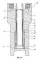
- FIG. 1Ais a conceptual side cross-sectional view of an expandable reamer of the present invention in a contracted state
- FIG. 1Bis a conceptual side cross-sectional view of an expandable reamer of the present invention in an expanded state
- FIG. 1Cis a partial cross-sectional view of the lower longitudinal end of an expandable reamer of the present invention.
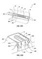
- FIG. 1Dis a perspective schematic view of one embodiment of a movable blade-retention apparatus and FIG. 1 D 2 is a partial sectional perspective schematic taken transverse to the longitudinal extent of the blade-retention apparatus of FIG. 1 D 1 ;
- FIG. 1Eis a partial conceptual side cross-sectional view of movable blades including ovoid structures of the present invention.
- FIG. 1Fis a conceptual side cross-sectional view of an expandable reamer of the present invention in a contracted state
- FIG. 1Gis a conceptual side cross-sectional view of an expandable reamer of the present invention in an expanded state
- FIG. 1His a side cross-sectional view of the upper longitudinal region of another embodiment of the expandable reamer of the present invention in a contracted state;
- FIG. 1Iis a side cross-sectional view of the lower longitudinal region of the expandable reamer shown in FIG. 1H ;
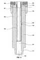
- FIG. 2Ais a conceptual side cross-sectional view of an expandable reamer of the present invention in a contracted state
- FIG. 2Bis a conceptual side cross-sectional view of an expandable reamer of the present invention in an expanded state
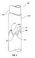
- FIG. 3is a conceptual perspective view of a pin guide sleeve of the present invention.
- FIG. 4Ais a conceptual side cross-sectional view of an expandable reamer of the present invention in a contracted state
- FIG. 4Bis a conceptual side cross-sectional view of an expandable reamer of the present invention in an expanded state
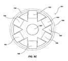
- FIG. 5Ais a schematic bottom view of a symmetric movable blade arrangement of an expandable reamer of the present invention in an expanded state;
- FIG. 5Bis a schematic bottom view of an asymmetric movable blade arrangement of an expandable reamer of the present invention in an expanded state;
- FIG. 5Cis a schematic bottom view of an expandable reamer of the present invention including a first set of movable blades configured to expand to a first outer diameter and a second set of movable blades configured to expand to a second diameter in an expanded state;
- FIGS. 6A and 6Billustrate side cross-sectional views of adjustable spacing elements in relation to movable blades of the present invention
- FIGS. 7A and 7Billustrate side cross-sectional views of a seal arrangement of the present invention
- FIG. 8Ashows a side cross-sectional view of a conventional compensator
- FIG. 8Bshows a side cross-sectional view of the compensator as shown in FIG. 8A disposed within movable blades of the present invention
- FIGS. 9A and 9Bdepict side cross-sectional views of an expandable reamer of the present invention, including a separation element for expanding the movable blades thereof, in a contracted state and expanded state, respectively;
- FIG. 10is a side cross-sectional view of an expandable reamer of the present invention including replaceable bearing pads;
- FIG. 11Ais a side cross-sectional view of an expandable reamer of the present invention including expandable bearing pads;
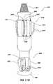
- FIG. 11Bis a side perspective view of a pilot bit attached to an expandable reamer of the present invention.
- FIG. 11Cis a schematic bottom view of the pilot bit and expandable reamer assembly shown in FIG. 11B ;
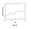
- FIG. 12is a conceptual depiction of a pressure signature during operation of the expandable reamer of the present invention.
- FIG. 13is a conceptual depiction of a pressure signature during operation of the expandable reamer of the present invention.
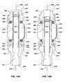
- FIGS. 14A and 14Billustrate side cross-sectional views of an expandable reamer of the present invention including a tailored fluid path for accentuating the pressure response in relation to expansion of the movable blades in a contracted state and an expanded state, respectively.
- FIGS. 1A and 1B of the drawingseach shows a conceptual schematic side view of an expandable reamer 10 of the present invention.
- Expandable reamer 10includes a tubular body 32 with a bore 31 extending therethrough, having movable blades 12 and 14 outwardly spaced from the centerline or longitudinal axis 25 of the tubular body 32 .
- Tubular body 32includes a male-threaded pin connection 11 as well as a female-threaded box connection 15 , as known in the art.
- Movable blades 12 and 14may each carry a plurality of cutting elements 36 .
- Cutting elements 36are shown only on movable blade 12 , as the cutting elements on movable blade 14 would be facing in the direction of rotation of the expandable reamer 10 and, therefore, may not be visible in the view depicted in FIG. 1 A.
- Cutting elements 36may comprise PDC cutting elements, thermally stable PDC cutting elements (also known as “TSPs”), superabrasive impregnated cutting elements, tungsten carbide cutting elements, and any other known cutting element of a material and design suitable for the subterranean formation through which a borehole is to be reamed using expandable reamer 10 .
- TSPsthermally stable PDC cutting elements
- superabrasive impregnated cutting elementstungsten carbide cutting elements
- tungsten carbide cutting elementsany other known cutting element of a material and design suitable for the subterranean formation through which a borehole is to be reamed using expandable reamer 10 .
- One particularly suitable superabrasive impregnated cutting elementis disclosed in U.
- PDC cutting elementsmay be positioned on a blade so, as to be circumferentially and rotationally offset from a radially outer, rotationally leading edge portion of a blade where a casing contact point is to occur.
- Such positioning of the cutters rotationally, or circumferentially, to the rotational rear of the casing contact point located on the radially outermost leading edge of the bladeallows the cutters to remain on proper drill diameter for enlarging the borehole, but are, in effect, recessed away from the casing contact point.
- Such an arrangementis disclosed and claimed in U.S. patent application Ser. No. 10/120,208 filed Apr. 10, 2002, the disclosure of which is incorporated herein by reference.
- the expandable reamer 10is shown in a contracted state, where the movable blades 12 and 14 are positioned radially or laterally inwardly.
- the outermost radial or lateral extent of movable blades 12 and 14may substantially coincide with or not exceed the outer diameter of the tubular body 32 .
- Such a configurationmay protect cutting elements 36 as the expandable reamer 10 is disposed within a subterranean borehole.
- the outermost radial or lateral extent of movable blades 12 and 14may exceed or fall within the outer diameter of tubular body 32 .
- Actuation sleeve 40may be positioned longitudinally in a first position, where apertures 42 are above actuation seal 43 .
- Drilling fluid(not shown) may pass through actuation sleeve 40 , thus passing by movable blades 12 and 14 .
- Actuation seal 43 and lower sleeve seal 45may prevent drilling fluid from interacting with movable blades 12 and 14 .
- sleeve-biasing element 44may provide a bias force to actuation sleeve 40 to maintain its longitudinal position.
- a reduced cross-sectional orifice 50may produce a force upon the actuation sleeve 40 .
- actuation sleeve 40As known in the art, drag of the drilling fluid through the reduced cross-sectional orifice 50 may cause a downward longitudinal force to develop on the actuation sleeve 40 . As the drilling fluid force on the actuation sleeve 40 exceeds the force generated by the sleeve-biasing element 44 , the actuation sleeve 40 may move longitudinally downward thereagainst. Thus, the longitudinal position of the actuation sleeve 40 may be modified by way of changing the flow rate of the drilling fluid passing therethrough. Alternatively, a collet or shear pins (not shown) may be used to resist the downward longitudinal force until the shear point of the shear pin or frictional force of the collet is exceeded.
- the downward longitudinal force generated by the drilling fluid moving through the reduced cross-sectional area orifice 50may cause a friable or frictional element to release the actuation sleeve 40 and may cause the actuation sleeve 40 to move longitudinally downward.
- the longitudinal position of the actuation sleeve 40may allow drilling fluid to be diverted to the inner surfaces 21 and 23 of movable blades 12 and 14 , respectively, via apertures or ports 42 .
- blade-biasing elements 24 , 26 , 28 , and 30may be configured to provide an inward radial or lateral force upon movable blades 12 and 14 .
- expandable reamer 10is shown in an expanded state in FIG. 1B , wherein movable blades 12 and 14 are disposed at their outermost radial or lateral position.
- FIG. 1Bshows an operational state of expandable reamer 10 wherein actuation sleeve 40 is positioned longitudinally so that apertures or ports 42 allow drilling fluid flowing through expandable reamer 10 to pressurize the annulus 17 formed between the outer surface of actuation sleeve 40 and inner radial surface of movable blades 12 and 14 to force movable blade 12 against blade-biasing elements 24 and 26 , as well as forcing movable blade 14 against blade-biasing elements 28 and 30 .
- the pressure applied to the inner surfaces 21 and 23may be sufficient so that movable blade 12 compresses blade-biasing elements 24 and 26 and may matingly engage the inner radial surface of retention element 16 as shown in FIG. 1 B.
- Regions 33 and 35indicate a portion of the tubular body 32 that may contain holes for disposing removable lock rods (not shown) as described in FIG. 1D for affixing retention element 16 and movable blade 12 thereto.
- the pressure applied to the inner surfaces 21 and 23may be sufficient so that movable blade 14 compresses blade-biasing elements 28 and 30 and may matingly engage the radial inner surface of retention element 20 as shown in FIG. 1 B.
- the movable blades 12 and 14 of expandable reamer 10 of the present inventionmay be caused to expand to an outermost radial or lateral position and the borehole may be enlarged by the combination of rotation and longitudinal displacement of the expandable reamer 10 .
- At least one movable blade 12 of the expandable reamer 10may be configured with a port 34 to aid in cleaning the formation cuttings from the cutting elements 36 affixed to the movable blades 12 and 14 during reaming.
- a port 34may be configured near the lower longitudinal cutting elements 36 on movable blade 12 and may be oriented, for example, 15° from horizontal, toward the upper longitudinal end of the expandable reamer 10 .
- a port 34may be installed in the horizontal direction, substantially perpendicular to the longitudinal axis 25 of tubular body 32 of the expandable reamer 10 .
- the present inventioncontemplates that a port 34 may be oriented as desired.
- Other configurations for communicating fluid from the interior of the tubular body 32 to the cutting elements 36 on the movable blades 12 and 14are contemplated, including a plurality of ports 34 on at least one movable blade.
- Movable blades 12 and 14may also be caused to contract radially or laterally.
- blade-biasing elements 24 , 26 , 28 , and 30may exert a radial or lateral inward force to bias movable blades 12 and 14 radially or laterally inward.
- taper 19may facilitate movable blades 12 and 14 returning radially or laterally inwardly during tripping out of the borehole if the blade-biasing elements 24 , 26 , 28 , and 30 fail to do so.
- impacts between the borehole and the taper 19may tend to move the movable blades 12 and 14 radially or laterally inward.
- FIG. 1Cshows a partial cross-sectional view of the lower longitudinal end of an expandable reamer 100 of the present invention including an actuation sleeve-biasing element 44 .
- inner sleeve stop 72 , outer housing 74 , transfer sleeve 109 , actuation sleeve-biasing element 44 , lower retainer 78 , end cap 118 , and various sealing elements 77may be disposed within the lower longitudinal bore of the tubular body 32 of the expandable reamer 100 .
- Expandable reamer 100may be configured with an actuation sleeve 40 having a reduced cross-sectional orifice 50 (not shown) as depicted in FIGS.
- actuation sleeve 40may be displaced longitudinally downward.
- the lower longitudinal end of actuation sleeve 40is shown as matingly engaging transfer sleeve 109 .
- the transfer sleeve 109may compress actuation sleeve-biasing element 44 , thus providing a returning force upon the actuation sleeve 40 .
- Actuation sleeve 40may be prevented from further longitudinal displacement by way of mating engagement of inner sleeve stop 72 at its upper longitudinal end.
- upper indentation 113 and lower indentation 110 formed within the outer housing 74may selectively position or retain the transfer sleeve 109 according to the forces thereon and the position of the lower longitudinal end thereof, which may be complementary in its geometry in relation to the geometry of indentations 113 and 110 as shown. Therefore, the expandable reamer 100 of the present invention may be configured to allow the actuation sleeve 40 to be selectively positioned and biased. Many other configurations for limiting or selectively positioning the actuation sleeve 40 of the present invention may be utilized, including collets, pins, friable elements, seating surfaces, or other elements of mechanical design as known in the art.
- FIGS. 1 D 1 and 1 D 2show an embodiment of a movable blade-retention apparatus 201 consistent with the embodiments of expandable reamer 10 , as shown in FIGS. 1A-1B , wherein removable lock rods 203 extend longitudinally along the tubular body 32 of the expandable reamer 10 at different circumferential placements, respectively.
- Retention block 206may be formed as an integral part of the tubular body 32 , or may be welded onto the tubular body 32 .
- removable lock rods 203are partially extending into holes 205 within retention block 206 formed within regions 33 and 35 (also depicted in FIGS.
- holes 205formed in the tubular body 32 in the regions 33 and 35 , as shown in FIGS. 1A-1C , allow for removable lock rods 203 to be inserted therethrough, extending between retention element 16 and retention body 205 , thus affixing retention element 16 to tubular body 32 .
- removable lock rods 203When fully installed, removable lock rods 203 extend substantially the length of retention block 206 , but may extend further, depending on how the removable lock rods 203 are affixed to the retention block 206 .
- Removable lock rods 203may be threaded, splined, pinned, welded or otherwise affixed to the retention block 206 .
- removable lock rods 203may be detached from the retention block 206 to allow for removal of retention element 16 as well as movable blade 12 .
- a retention element and/or a movable blade of the expandable reamermay be removed, replaced, or repaired by way of removing the removable lock rods 203 from the holes 205 within the body of the expandable reamer 10 .
- many alternative removable retention configurationsare possible including pinned elements, threaded elements, dovetail elements, or other connection elements known in the art to retain movable blade 12 .
- Movable blade 14 and/or any other movable bladesmay be retained in a similar manner.
- circumferential seal assembly 207carried in groove 209 on the exterior of blade 12 to prevent debris and contaminants from the wellbore from entering the interior of expandable reamer 10 .
- the cross-sectional shape of the movable blade 12 as it extends through the retention element 16may be oval or elliptical. Such a shape may prevent binding of the movable blade 12 as it is moved laterally inwardly and outwardly during use.
- the shape of the longitudinal sides of the movable bladesmay not be straight.
- each longitudinal side of a movable blademay comprise an oval, elliptical, or other arcuate shape.
- the sidesneed not be symmetrical, but may be if symmetry is desirable.
- ovoid structures 37may be employed upon movable blades 12 and 14 in order to inhibit cutting elements 36 from being damaged due to excessive or undesirable contact with the borehole.
- FIG. 1Ealso shows that ovoid structures 37 may be disposed along the outer radial or lateral extent of movable blades 12 and 14 retained within tubular body 32 by way of retention elements 16 and 20 , respectively.
- Cutting elements 36are not shown on movable blade 14 for clarity, as such cutting elements 36 may be facing in the direction of rotation of the movable blades 12 and 14 .
- ovoid structures 37may be desirable as inhibiting or preventing damage to associated cutting elements 36 disposed thereon, respectively.
- Ovoid structures 37may comprise a sintered tungsten carbide compact having a domed or ovoidal top surface.
- ovoid structures 37may comprise generally or partially planar or flat, cylindrical, conical, spherical, rectangular, triangular, or arcuate shapes, and/or be otherwise geometrically configured and suitably located to provide protection to associated cutting elements 36 .
- the present inventionis not limited only to sintered tungsten carbide ovoid structures; ovoid structures may comprise other metals, sintered metals, alloys, diamond, or ceramics.
- cutting elements 36 disposed on the movable blades 12 and 14may engage the sidewall of the borehole in an undesirable fashion.
- cutting elements 36may be damaged by prematurely or excessively contacting the sidewall of the borehole.
- Ovoid structures 37 disposed along the movable blades 12 and 14may inhibit or prevent excessive or premature contact between the sidewall of the borehole and the cutting elements 36 on the movable blades 12 and 14 .
- damage to cutting elements 36may occur when movable blades 12 and 14 may become oriented so that the upper longitudinal ends thereof are at different lateral positions than the lower longitudinal ends thereof, respectively.
- a movable blademay longitudinally tilt or rotate, as shown in relation to longitudinal axis 25 of the tubular body 32 of the expandable reamer.
- Movable blade 12is longitudinally tilted so that its upper longitudinal end is closer to longitudinal axis 25 than its lower longitudinal end.
- the cutting elements 36 disposed on the upper longitudinal region of movable blade 12may excessively or undesirably contact the sidewall of the borehole and become damaged in the absence of ovoid structures 37 .
- movable blade 14is shown in an orientation where its upper longitudinal end is more distant from longitudinal axis 25 than its lower longitudinal end. Therefore, in the absence of ovoid structures 37 , cutters (not shown) on the lower longitudinal end of movable blade 14 may become damaged due to excessive or undesirable contact with the sidewall of the borehole.
- ovoid structures 37may be sized and positioned to initially exhibit substantially the same exposure as cutting elements 36 proximate thereto. However, ovoid structures 37 may also exhibit a-relatively lower wear resistance to the formation. Thus, upon initially disposing the expandable reamer within the borehole, the ovoid structures 37 may wear away, thus allowing the cutting elements 36 to assume a selected depth of cut into the formation. This may be advantageous because an ovoid structure 37 may prevent initial impact loading by making contact with the borehole or other surface at substantially the same exposure as the cutting elements 36 proximate thereto. Further, the ovoid structures 37 , upon wearing, may limit contact between cutting elements 36 proximate thereto and the formation according to the amount of wear thereon. Additionally, cutting elements 36 and associated ovoid structures 37 may be replaced and ground (if necessary) to a desirable exposure, respectively.
- ovoid structures 37may also inhibit excessive contact between associated cutters and the formation during unstable motion of the expandable reamer, i.e., whirling or when the expandable reamer is rotated inside the casing.
- movable blades 12 and 14need not exhibit particular orientations or be tilted in order to benefit from ovoid structures 37 .
- Ovoid structures 37may be utilized within any of the embodiments described herein, without limitation.
- FIG. 1Eis merely illustrative of one possible circumstance where ovoid structures 37 may prevent damage to associated cutting elements 36 , and many other circumstances may exist and are contemplated by the present invention.
- expandable reamer 410is shown in FIGS. 1F and 1G , wherein the actuation sleeve 440 may be configured to pass substantially longitudinally past the lower longitudinal extent of the movable blades 412 and 414 upon actuation thereof.
- FIGS. 1F-1Gillustrate an embodiment of an expandable reamer 410 of the present invention, wherein actuation sleeve 440 may be used to actuate the movable blades 412 and 414 .
- Expandable reamer 410includes a tubular body 432 with a bore 431 extending therethrough and movable blades 412 and 414 outwardly spaced from the centerline or longitudinal axis 425 of the tubular body 432 , wherein each movable blade 412 and 414 may carry a plurality of cutting elements 436 , as known in the art.
- Tubular body 432also includes a male-threaded pin connection 411 as well as a female-threaded box connection 415 .
- Cutting elements 436are shown only on movable blade 412 for clarity, as the cutters on movable blade 414 may be typically facing in the direction of rotation of the tubular body 432 and, therefore, may not be visible in the view depicted in FIGS. 1F and 1G .
- the expandable reamer 410is shown in a contracted state, wherein the movable blades 412 and 414 are positioned radially or laterally inwardly.
- Actuation sleeve 440may be positioned longitudinally in a first position near the upper longitudinal end of the tubular body 432 , so that the exterior of the upper end 451 of the actuation sleeve 440 is positioned to seal against the actuation seal 443 . Further, actuation seal 443 and lower sleeve seal 445 may seal against the actuation sleeve 440 .
- drilling fluidmay pass through actuation sleeve 440 without communicating with the inner surfaces 421 and 423 of movable blades 412 and 414 , repectively, so long as the actuation sleeve 440 is appropriately longitudinally positioned by way of shear pins, interlocking members, frictional elements, collets, friable members, or otherwise as known in the art.
- Actuation sleeve 440may include a reduced cross-sectional orifice 450 , which, in turn may produce a downward longitudinal force as drilling fluid passes therethrough. Upon sufficient downward longitudinal force developing, the actuation sleeve 440 may be displaced longitudinally, as shown in FIG. 1F , and may be guided by bushing elements 447 and 449 . Longitudinal displacement of actuation sleeve 440 may allow drilling fluid to act upon the movable blades 412 and 414 and may cause movable blades 412 and 414 to expand radially or laterally outwardly, matingly engaging retention elements 416 and 420 , respectively, as shown in FIG.
- the expandable reamer 410 as depicted in FIGS. 1F and 1Gmay be a “one shot” tool, wherein operation without drilling fluid communication to the movable blades 412 and 414 may not be possible without resetting the actuation sleeve 440 position as shown in FIG. 1 F.
- actuation sleeve lip 463may be configured to engage a wireline tool in order to apply an upward longitudinal force to the actuation sleeve 440 and position the actuation sleeve 440 to the longitudinal position shown in FIG. 1F from the longitudinal position shown in FIG. 1 G.
- movable blades 412 and 414may return radially or laterally inwardly as the forces applied thereto by way of blade-biasing elements 424 and 426 , as well as 428 and 430 , respectively, exceed the forces of the drilling fluid upon the inner surfaces 421 and 423 of movable blades 412 and 414 , respectively.
- taper 419may encourage radially or laterally inward movement of movable blades 412 , 414 by interaction with the borehole or casing.
- the expandable reamer 410By configuring the expandable reamer 410 with an actuation sleeve 440 that may be displaced substantially the longitudinal length of the movable blades 412 and 414 , several advantages may be realized. For instance, as may be seen in FIG. 1F , contraction of the movable blades 412 and 414 may not be hindered by minor debris within the relatively large bore 417 . Comparatively, the relative size of annulus 17 (shown in FIGS. 1A-1B ) between the actuation sleeve 40 and the inner surfaces 21 and 23 of movable blades 12 and 14 may impede retraction of the movable blades 12 and 14 , especially where debris exists therein.
- FIG. 1Hshows the upper longitudinal region of another embodiment of an expandable reamer 710 , wherein the actuation sleeve 740 may be configured to longitudinally pass through the longitudinal region occupied by the movable blades 712 and 714 .
- Expandable reamer 710includes a tubular body 732 with bore 731 extending therethrough and movable blades 712 and 714 outwardly spaced from the centerline or longitudinal axis 725 of the tubular body 732 .
- Each movable blade 712 and 714may carry a plurality of cutting elements (not shown for clarity).
- movable blades 712 and 714may carry at least one ovoid structure 737 . Ovoid structures 737 are shown in FIG.
- Tubular body 732also includes a female-threaded box connection 715 at its upper longitudinal end and a male-threaded pin connection 711 at its lower longitudinal end.
- Expandable reamer 710is shown in a contracted state, wherein the movable blades 712 and 714 are positioned radially or laterally inwardly.
- Actuation sleeve 740is positioned longitudinally near the upper longitudinal end of the tubular body 732 .
- Upper sleeve housing 744may include inner seal element 745 for sealing against the actuation sleeve 740 as well as outer seal element 746 for sealing against the interior of tubular body 732 .
- lower sleeve seal 749 disposed within retaining sleeve 748may be configured for sealing against the actuation sleeve 740 . Accordingly, as shown in FIG. 1H , drilling fluid (not shown) may pass through actuation sleeve 740 while substantially sealed from communication with movable blades 712 and 714 .
- Actuation sleeve 740may include a reduced cross-sectional orifice 750 and may be displaced longitudinally in a fashion similar to the embodiments described hereinabove in that drilling fluid flowing therethrough may produce a longitudinally downward force on the actuation sleeve 740 .
- FIG. 1Halso illustrates that an orifice body 751 may include reduced cross-sectional orifice 750 sealed within actuation sleeve 740 by way of orifice body seal 753 .
- the orifice body 751 and associated reduced cross-sectional orifice 750may be replaced or modified by removing orifice body 751 from the interior of the actuation sleeve 740 .
- Collet sleeve 747 having a male feature 741 fitting into a complementary female feature 742 within the actuation sleeve 740may retain actuation sleeve 740 in its position as shown in FIG. 1H until the longitudinally downward force generated by way of the flow of drilling fluid through the reduced cross-sectional orifice 750 exceeds the retaining force supplied thereby.
- Longitudinal displacement of actuation sleeve 740 below inner seal element 745may allow drilling fluid to act upon inner surfaces 721 and 723 of movable blades 712 and 714 , respectively, causing them to expand radially or laterally outwardly against the opposing forces of blade-biasing elements 724 , 726 , 728 , and 730 , retained by retention elements 716 and 720 , respectively.
- movable blades 712 and 714may return radially or laterally inwardly as the forces applied thereto by way of blade-biasing elements 724 and 726 , as well as 728 and 730 , respectively, exceed the forces of the drilling fluid upon the inner surfaces 721 and 723 of movable blades 712 and 714 , respectively.
- retaining sleeve 748is sized and configured so that the actuation sleeve 740 may be disposed longitudinally therein. Therefore, upon sufficient force, the actuation sleeve 740 may be longitudinally displaced so that its lower longitudinal end matingly engages the longitudinally lower end of the retaining sleeve 748 . In such a position, the actuation sleeve 740 may not coincide with any portion of the longitudinal extent of movable blades 712 and 714 . As mentioned hereinabove, such a configuration may facilitate movable blades 712 and 714 , once expanded, to return radially or laterally inwardly.
- Retaining sleeve 748may be prevented from longitudinal movement by way of indentation 756 and complementary male feature 759 disposed therein. Further, as shown in FIG. 1I , retaining sleeve 748 may include longitudinal slots 758 configured to increase the flow area available for drilling fluid passing through the expandable reamer 710 . More specifically, the actuation sleeve 740 may be disposed within the retaining sleeve 748 , such that drilling fluid may pass through both the reduced cross-sectional orifice 750 and the longitudinal slots 758 .
- One way to do sowould be to configure the lengths of the actuation sleeve 740 and the retaining sleeve 748 so that the longitudinal upper surface of the actuation sleeve 740 is positioned below the upper extent 761 of the longitudinal slots 758 . Such a configuration may improve the drilling fluid flow characteristics of the expandable reamer 710 .
- FIGS. 2A-2Billustrate another-exemplary embodiment of an expandable reamer 210 of the present invention, wherein a restriction element 266 may be used to actuate the movable blades 212 and 214 .
- Expandable reamer 21 0includes a tubular body 232 with a bore 231 extending therethrough and movable blades 212 and 214 outwardly spaced from the centerline or longitudinal axis 225 of the tubular body 232 , wherein each movable blade 212 and 214 may carry a plurality of cutting elements 236 .
- Tubular body 232may also include a male-threaded pin connection 211 as well as a female-threaded box connection 215 .
- Cutting elements 236are shown only on movable blade 212 for clarity, as the cutting elements on movable blade 214 may typically be facing in the direction of rotation of the expandable reamer 210 and, therefore, may not be visible in the view depicted in FIGS. 2A and 2B .
- the expandable reamer 210is shown in a state where the movable blades 212 and 214 are positioned radially or laterally inwardly.
- Actuation sleeve 240may be positioned longitudinally in a first position near the upper longitudinal end of the tubular body 232 , so that the radial periphery of the upper end 250 of the actuation sleeve 240 is positioned to seal against the actuation seal 243 .
- drilling fluid(not shown) may pass through actuation sleeve 240 , passing longitudinally by movable blades 212 and 214 .
- Actuation seal 243 and lower sleeve seal 245may prevent drilling fluid from interacting with movable blades 212 and 214 , so long as the actuation sleeve 240 is appropriately positioned.
- the actuation sleeve 240may be releasably restrained by way of shear pins, interlocking members, frictional elements, or friable members, or otherwise may be configured to maintain its longitudinal position under a wide range of operating conditions.
- a restriction element 266may be deployed within the drilling fluid stream and may ultimately be disposed within sleeve seat 252 , as shown in FIG. 2 B.
- the actuation sleeve 240 longitudinal positionmay be as shown in FIG. 2 A.
- drilling fluid pressuremay cause the actuation sleeve 240 to be displaced longitudinally to a position shown in FIG. 2 B.
- drilling fluidmay pass into the annulus 217 formed between the inner surfaces 221 and 223 of movable blades 212 and 214 , respectively, and the actuation sleeve 240 .
- blade-biasing elements 224 , 226 , 228 , and 230may be configured to provide an inward radial or lateral force upon movable blades 212 and 214
- drilling fluid pressure acting upon the inner surfaces 221 and 223may generate a force that exceeds the inward radial or lateral force and movable blades 212 and 214 may be disposed radially or laterally outward, thus matingly engaging retention elements 216 and 220 , respectively.
- Retention elements 216 and 220may be affixed to tubular body 232 by way of-removable lock rods (not shown) disposed therethrough and within regions 233 and 235 as described hereinabove in relation to FIGS. 1A , 1 B, and 1 D.
- the movable blades 212 and 214 of expandable reamer 210may be caused to expand to an outermost position and the borehole may be enlarged by the combination of rotation and longitudinal displacement of the expandable reamer 210 .
- the longitudinal position of the actuation sleeve 240 after the restriction element 266 is deployedmay be maintained or affixed by any number of means, such as interlocking members, pins, frictional members, or as otherwise known in the art.
- the expandable reamer 210may be configured as a “one shot” tool, wherein once the movable blades 212 and 214 are allowed to expand, the actuation system may not be reset without removing the tool from the borehole.
- restriction element 266 and actuation sleeve 240may be configured to allow for wireline tools or other means to reset the position of the actuation sleeve 240 and thereby reset the operating state of the expandable reamer 210 while within the borehole.
- the actuation sleeve 240may be configured with grooves 258 formed within but not through the thickness of the actuation sleeve 240 that do not extend below the lower sleeve seal 245 in the position as shown in FIG. 2 A. However, as shown in FIG.
- the grooves 258extend both longitudinally above and longitudinally below the lower sleeve seal 245 , which allows drilling fluid moving into the annulus 217 to pass longitudinally downwardly and into grooves 258 , past lower sleeve seal 245 , through scallops or holes 253 formed in the lower longitudinal end of actuation sleeve 240 , thereby passing into the bore 231 of the tubular body 232 of expandable reamer 210 .
- the drilling fluidmay pass through the expandable reamer 210 ultimately to be delivered to another downhole tool, pilot drill bit, or other drilling implement.
- the actuation sleeve 240may include burst discs or other friable members that allow drilling fluid to communicate between the bore 231 of the tubular body 232 of expandable reamer 210 and annulus 217 when actuation sleeve 240 allows drilling fluid to act upon the inner surfaces 221 and 223 of movable blades 212 and 214 , respectively.
- At least one movable blade of the expandable reamer 210may be configured with a port 234 to aid in cleaning the formation cuttings from the cutting elements 236 affixed to the movable blades 212 and/or 214 during reaming/drilling.
- Port 234may be configured near the lower longitudinal cutting elements 236 on the movable blade 212 and may be oriented at about 15° from the horizontal toward the upper longitudinal end of the reamer.
- a port 234may be oriented as desired.
- Port 234may be located near to, or actually as a part of, movable blade 212 , as shown.
- Other configurations for communicating fluid from the interior of the tubular body 232 to the cutting elements 236 on the movable blades 212 and 214are contemplated, including a plurality of ports 234 on at least one movable blade.
- movable blades 212 and 214may be caused to contract when the drilling fluid pressure decreases sufficiently so that blade-biasing elements 224 , 226 , 228 , and 230 may exert a radially or laterally inward force to bias movable blades 212 and 214 radially or laterally inward.
- a taper 219may facilitate movable blades 212 and 214 returning radially or laterally inwardly via contact between the taper 219 and any other surface or body.
- a pin guide sleeve assembly 360 as shown in FIG. 3may be used to position an actuation sleeve 368 within an expandable reamer of the present invention.
- an actuation sleevemay be used to cause movable blades of an expandable reamer to deploy. More specifically, the position of an actuation sleeve may cause the movable blades of the expandable reamer of the present invention to expand or contract.
- the position of an actuation sleeve 368may be adjusted by way of a pin guide sleeve assembly 360 and thus may cause movable blades of an expandable reamer to deploy or retract.
- FIG. 3shows a pin guide assembly 360 wherein a groove 366 is formed within sleeve 362 .
- Pin 364may be disposed within the groove 366 and pin 364 may be affixed to an actuation sleeve 368 of an expandable reamer of the present invention.
- actuation sleeve 368may be caused to move within an expandable reamer.
- Groove 366may comprise a pattern of peaks and valleys, as represented by the regions A 1 , B 1 , C 1 , D 1 , and A 2 .
- groove 366may be configured to extend about the entire circumference of the sleeve 362 in a repeating, continuous manner, so that the pin 364 may be caused to repeatedly traverse within the groove 366 and about the circumference of the sleeve 362 .
- groove 366may comprise a series of alternating upwardly sloping and downwardly sloping arcuate paths.
- the actuation sleeve 368may be configured with a restoring upward force by way of a biasing element as described hereinabove.
- the pin 364may be traversed within the groove 366 to position B 1 by way of a relatively high flow rate of drilling fluid, for instance, 800 gallons per minute. Sufficient reduction of the flow rate of drilling fluid may cause the restoring force of a biasing element to cause the pin 364 and actuation sleeve 368 to move upward, into position C 1 . Similarly, the pin 364 and actuation sleeve 368 may be caused to move to position D 1 via a relatively high flow rate of drilling fluid. Further, sufficient reduction of the flow rate of drilling fluid may cause the pin 364 and actuation sleeve 368 to move to position A 2 .
- a relatively high flow rate of drilling fluidfor instance, 800 gallons per minute.
- the patternmay continue around the entire circumference of the sleeve 362 , and may be continuous so that the sequence may be repeated any number of times.
- the groove 366 as shown in FIG. 3may include peaks and valleys B 2 , C 2 , D 2 , A 3 , B 3 , C 3 , and D 3 (not shown) on the portion of the circumference of the sleeve 362 not visible in FIG. 3 .
- the interaction between the flow rate and the restoring forcemay be configured so that drilling fluid flow rates used during typical operation, for instance, 400 gallons per minute flow rate of drilling fluid, may cause the pin 364 to traverse only a portion of the distance between either A 1 and B 1 or C 1 and D 1 (or generally any upper and lower points within the groove 366 ). This may be advantageous so that the operating condition of the expandable reamer may not change unexpectedly.
- the above descriptiondescribes different longitudinal positions of the actuation sleeve 368 , the present invention contemplates that rotation of pin 364 within pin guide sleeve assembly 360 may also cause actuation of movable blades within an expandable reamer of the present invention, without limitation.
- an expandable reamer sub 310 with a movable blade 312 having an expanded outermost diameter that may exceed the diameter that is ordinarily attainable via conventional expandable reamersis shown in FIGS. 4A and 4B .
- conventional reamersmay only expand up to about 20% of their initial diameter.
- the expandable reamer of the present inventionmay expand up to about 40% of its initial diameter.
- the expandable reamer of the present inventionmay expand in excess of 20% of its initial diameter and up to about 40% of its initial diameter.
- the expandable reamer sub of the present inventionmay include a blade that expands from an initial diameter of about 10.5 inches to an expanded diameter of about 14.75 inches.
- Conventional expandable reamersmay be limited in expanding from an initial diameter of about 10.5 inches to an expanded diameter of about 14.75 inches.
- the present inventionis not limited in its application to any particular size and may be applied to numerous sizes and configurations.
- Expandable reamer sub 310includes tubular body 332 , bore 331 , and movable blade 312 carrying cutting elements 336 .
- the inner surface 321 of movable blade 312may extend into the space near and past the longitudinal axis 325 (center) of the expandable reamer sub 310 . Due to space limitations, where multiple movable blades are disposed with overlapping longitudinal extents, the radially inner surfaces may only extend to the longitudinal axis 325 of the expandable reamer sub 310 .
- Retaining structures 350 and 352may be disposed near the center of the expandable reamer sub 310 , as shown in FIGS. 4A and 4B . Retaining structure 350 , as shown in FIGS.
- the bore 331 extending through the expandable reamer sub 310may be shaped to allow drilling fluid to pass around the movable blade 312 while contracted within the expandable reamer sub 310 .
- each expandable reamer subs 310may be assembled together or to other drilling equipment via female-threaded box connection 315 and male-threaded pin connection 311 . Accordingly, each movable blade 312 of each expandable reamer sub 310 may be aligned circumferentially as desired in relation to one another. For instance, three expandable reamer subs 310 may be assembled so that each movable blade 312 is circumferentially separated from another movable blade 312 by about 120°. Of course, many different assemblies containing different numbers of movable blades in different arrangements are contemplated by the present invention.
- movable blade 312may be pinned into place by way of shear pins (not shown) disposed within holes 361 and 363 extending into respective holes within movable blade 312 , as known in the art. Further, bias forces applied by way of blade-biasing elements 324 and 326 may provide forces to retain the movable blade 312 against the retaining structures 350 and 352 . However, as drilling fluid pressure may be increased, the forces generated thereby may cause shear pins (not shown) within holes 361 and 363 and extending into movable blade 312 to fail.
- the pressure of the drilling fluid on the inner surface 321 of the movable blade 312may cause the movable blade 312 to be disposed radially or laterally outwardly, matingly engaging retention element 316 as shown in FIG. 4 B.
- Retention element 316may be affixed to tubular body 332 of expandable reamer sub 310 by way of removable lock rods (not shown) disposed within holes (not shown) in regions 333 and 335 as described hereinabove.
- the movable blade 312may be biased by the blade-biasing elements 324 and 326 toward the position shown in FIG. 4 A.
- taper 319may encourage the movable blade 312 to return radially or laterally inward.
- FIG. 5Aa bottom cross-sectional view of an expandable reamer 80 of the present invention is shown schematically wherein the movable blades 82 , 84 , and 86 are arranged circumferentially symmetrically within tubular body 83 about the bore 87 of the expandable reamer 80 . Put another way, adjacent movable blades 82 , 84 , and 86 are separated by about 120° from one another.
- FIG. 5Bshows a schematic bottom cross-sectional view of an expandable reamer 81 of the present invention wherein movable blades 82 , 84 , and 86 are configured in a circumferentially asymmetrical arrangement within tubular body 83 about bore 87 of the expandable reamer 81 .
- movable blades 82 , 84 , and 86are positioned at their outermost radial or lateral position, thus substantially conforming to reference diameter 88 .
- movable blade positions and configuration embodimentsare possible and are contemplated by the present invention.
- movable blades 82 , 84 , and 86may be positioned along a general helix or spiral with respect to the longitudinal axis of the reaming assembly.
- the movable blade shapesmay be tapered, angled, or otherwise configured.
- movable blades 82 , 84 , and 86may be displaced along helical, lateral, or spiral paths, or other various displacement paths to effect overall radial or lateral displacement.
- FIG. 5Cschematically shows a cross-sectional bottom view of an expandable reamer 181 of the present invention where movable blades 182 , 186 , and 190 are configured in a circumferentially symmetric arrangement about bore 187 and are shown at their outermost radial or lateral positions, substantially conforming to reference diameter 194 .
- movable blades 184 , 188 , and 192are configured in a circumferentially symmetric arrangement about bore 187 and are shown at their outermost radial or lateral positions, thus substantially conforming to reference diameter 196 .
- movable blades 182 , 184 , 186 , 188 , 190 , and 192may be positioned at substantially the outer diameter of the tubular body 183 . Further, movable blades 182 , 186 , and 190 may be configured to actuate or be displaced radially or laterally outwardly under operating conditions different from movable blades 184 , 188 , and 192 . Conversely, movable blades 182 , 186 , and 190 may be configured to actuate or be displaced outwardly under substantially the same operating conditions as movable blades 184 , 188 , and 192 . Accordingly, as may be seen from FIG. 5C , the expandable reamer of the present invention contemplates different sets of movable blades corresponding to different effective drilling diameters.
- adjustable spacer elementsmay be employed so that an expandable reamer may be adjustable in its reaming diameter. Such a configuration may be advantageous to reduce inventory and machining costs, and for flexibility in use of the expandable reamer.
- FIGS. 6A and 6Bshow adjustable spacer elements 288 and 290 that may be replaced and/or adjusted. More specifically, for example, length “L” as shown in FIG. 6B may be modified so that the outermost radial or lateral position of movable blade 282 may be adjusted accordingly. Adjustable spacer elements 288 and 290 may be disposed within blade-biasing elements 292 and 294 as shown in FIG.
- adjustable spacer elements 288 and 290may allow for a single movable blade design and spacing element design to be used in various borehole sizes and applications.
- the expandable reamer of the present inventionincluding adjustable spacer elements 288 and 290 , may enlarge a particular section of borehole to a first diameter, then may be removed from the borehole and another set of adjustable spacer elements having a different length “L” may replace adjustable spacer elements 288 and 290 , then the expandable reamer may be used to enlarge another section of borehole at a second diameter.
- minor adjustment of the outermost lateral position of the movable blademay be desirable during drilling operations by way of threads or other adjustment mechanisms when adjustable spacer elements 288 and 290 are affixed to either the movable blade 282 or retention element 284 .
- a T-shaped seal 380comprising a relatively soft material, such as VITONTM, may be disposed adjacent to one or more relatively stiff backup seals 384 or 382 having a wiping surface 387 or 389 including at least two ridges 390 or 392 , respectively. More specifically, the width “W” of the T-shaped seal 380 may be about 0.585 inch, while the height “H ” of the backup seals 382 and 384 may be about 0.245 inch.
- backup seals 384 and 382are relatively stiff, they must each have one cut or slice therethrough to allow the backup seal 384 or 382 to collapse to a reduced diameter for insertion and. subsequently enable the seal to open to its larger, normal diameter and fit into the groove with T-shaped seal 380 . When a backup seal 382 or 384 is in place, it returns to its normal diameter adjacent T-shaped seal 380 . Such a configuration may be advantageous for inhibiting interaction between the T-shaped seal 380 and contaminants. More specifically, as shown in FIG. 7B , upon compression of and subsequent applied differential pressure to T-shaped seal 380 by way of adjacent surface 399 , the backup seals 384 and 382 may contact the adjacent surface 399 .
- one of the backup seals 384 or 382contacts the surface 399 prior to the T-shaped seal 380 , according to the direction of travel. Ridges 390 and 392 may therefore facilitate removal of contaminants from the surface 399 and thereby inhibit contaminants from contacting T-shaped seal 380 . Ridges 390 and 392 are one possible configuration for backup seals 384 or 382 ; however, any nonplanar surface geometry may be used as well. Of course, relative motion between the T-shaped seal 380 and another surface may be anticipated in one direction only. Therefore, one backup seal configured with ridges and located adjacent the T-shaped seal 380 preceding the anticipated direction of movement may be sufficient to protect the T-shaped seal 380 .
- compensator systemsmaybe employed in combination with any dynamic seals of the present invention.
- a compensator systemsuch as the compensator system for roller cone rotary drill bits disclosed in U.S. Pat. No. 4,727,942, assigned to the assignee of the present invention, and incorporated herein in its entirety by reference, may be included within the expandable reamer of the present invention.
- shaped cavity 472may be formed wherein the end 479 thereof may allow communication with drilling fluid.
- the flexible diaphragm 474 and protector cup 473may be disposed therein, as shown in FIG. 8 A.
- the chamber formed between the, flexible diaphragm 474 and the protector cup 473may be filled with lubricant 477 .
- the compensator cap 482 , snap ring 488 , lubricant plug 484 , and sealing element 486may allow for assembly of the compensator 470 , as well as replacement of the lubricant 477 , protector cup 473 , or flexible diaphragm 474 .
- Compensator 470may substantially equalize drilling fluid pressure with lubricant pressure and may cause lubricant 477 to be supplied to a seal (not shown).
- Flexible diaphragm 474 having a small perforation 476 thereinmay be exposed on one side to the pressure of the drilling fluid and on the other side to lubricant 477 supplied to a bearing or seal (not shown). If the pressure of the lubricant 477 exceeds the pressure of the drilling fluid, a portion of lubricant 477 may be released through the small perforation 476 into the drilling fluid, thereby substantially equalizing the pressure of the lubricant 477 to the drilling fluid pressure.
- Lubricant delivery tube 480may typically communicate with a seal (not shown), thereby supplying lubricant 477 thereto.
- compensators 470 , 471may be disposed within the movable blades 590 and 592 , affixed to tubular body 571 by way of retention elements 572 and 570 , respectively.
- Movable blade 590includes seal elements 582 and 584 disposed in grooves 583 and 585 extending about an exterior thereof, while movable blade 592 includes seal elements 586 and 588 disposed in grooves 587 and 589 extending about an exterior thereof.
- Compensator 470acts upon the lubricant in communication with a circumferential area on the exterior of movable blade 590 located between seal elements 582 and 584 while compensator 471 acts upon the lubricant in communication with a circumferential area on the exterior of movable blade 592 located between seal elements 586 and 588 . More specifically, compensator 470 may supply lubricant to seal elements 582 and 584 via lubricant delivery tubes 480 . Similarly, compensator 471 may supply lubricant to seal elements 586 and 588 via lubricant delivery tubes 480 . Accordingly, as movable blades 590 and 592 move radially or laterally inwardly and outwardly, compensators 470 , 471 move therewith, respectively.
- seal elements 582 , 584 , 586 and 588may preferentially prevent lubricant from passing thereby in relation to radially outward seal elements 582 and 586 , respectively.
- radially inward seal elements 584 and 588may be held in greater compression than radially outward seal elements 582 and 586 .
- Such a configurationmay prevent lubricant from contacting blade-biasing elements 574 , 576 , 578 , and 580 , and may further prevent debris from entering across radially outward seal elements 582 and 586 .
- a compensatormay be disposed, sized, and oriented within the tubular body of an expandable reamer of the present invention as physical size allows. For instance, it may be preferred to orient the end 479 of the shaped cavity 472 to communicate with the exterior of the movable blades 590 and 592 .
- a compensatormay be employed with respect to lubricant in communication with roller or thrust bearings, bushings, static seals, actuation sleeve seals, or any other moving elements within the expandable reamer of the present invention, without limitation.
- a separation element actuation systemmay actuate as well as maintain the cleanliness and functionality of the movable blades 512 and 514 of expandable reamer 510 of the present invention.
- FIGS. 9A and 9Billustrate an expandable reamer 510 of the present invention including movable blades 512 and 514 outwardly spaced from the centerline or longitudinal axis 525 of the tubular body 532 , affixed therein by way of retention elements 516 and 520 , respectively, and carrying cutting elements 536 (only shown on movable blade 512 for clarity).
- Tubular body 532includes a bore 531 therethrough for conducting drilling fluid as well as a male-threaded pin connection 511 and a female-threaded box connection 515 .
- a separation element 560including a reduced cross-sectional orifice 550 , may also comprise sealing element 543 .
- drilling fluidmay act upon the upper surface 533 of one side of the separation element 560
- another fluidsuch as oil, acts upon the lower surface 535 of the separation element 560 .
- Such a configurationmay substantially inhibit drilling fluid from contacting the inner surfaces 521 and 523 of movable blades 512 and 514 . Accordingly, as may be seen in FIGS.
- an upper chamber 513 and the annulus 517 formed between the separation element 560 and the inner surfaces 521 and 523 of the movable blades 512 and 514may be sealed from drilling fluid passing through expandable reamer 510 by sealing element 543 , as well as lower sealing element 545 .
- Upper chamber 513 and annulus 517may be filled with a fluid by way of port 549 , which may be sealed otherwise by way of a threaded plug or as otherwise configured during use of the expandable reamer 510 .
- separation element 560may be positioned longitudinally in a first position, as shown in FIG. 9 A.
- Drilling fluidmay pass through separation element 560 , thus passing by movable blades 512 and 514 , and exiting the separation element 560 at its lower longitudinal end.
- a shear pin (not shown) or other friable element (not shown)may restrain separation element 560 in its initial longitudinal position, as shown in FIG. 9 A.
- the reduced cross-sectional orifice 550may produce a force upon the separation element 560 and may cause a friable or frictional element (not shown) to release the separation element 560 and allow the separation element- 560 to move longitudinally downward.
- fluid within the upper chamber 513may be transferred into the annulus 517 and pressure may develop therein.
- pressure developed within annulus 517acts on the inner surfaces 521 and 523 of movable blades 512 and 514 , respectively, against forces generated by way of blade-biasing elements 524 , 526 , 528 , and 530 .
- Sufficient pressure acting upon the inner surfaces 521 and 523may cause the movable blade 512 and 514 to move radially or laterally outwardly to an outermost radial or lateral position, matingly engaging retention elements 516 and 520 , respectively, as shown in FIG. 9 B.
- the expandable reamer 510may substantially return to its initial operational state, as shown in FIG. 9 A. More specifically, blade-biasing elements 524 , 526 , 528 , and 530 , in conjunction with or independent of taper 519 , may cause movable blades 512 and 514 to return radially or laterally inwardly, thus causing separation element 560 to return longitudinally upwardly.
- movable blades of the present inventionmay be separated from drilling fluid by way of a fixed barrier.
- the separation element 560may be fixed within the tubular body 532 by way of bolts or pins, or as otherwise configured.
- pressurized fluid or gasmay be supplied within annulus 517 by way of a downhole pump or turbine via port 549 . Accordingly, the movable blades 512 and 514 may be deployed thereby.
- Such a configurationmay allow for expandable reamer 510 to be expanded irrespective of drilling fluid flow rates or pressures.
- the movable bladesmay communicate with a nondrilling fluid pressurized by a downhole pump or turbine.
- the actuation sleevemay be fixed in a position separating drilling fluid from communication with any movable blades and a port may be provide to pressurize the movable blades.
- FIG. 10shows a partial side cross-sectional view of an expandable reamer 810 including replaceable bearing pads 870 and 872 .
- Expandable reamer 810includes movable blades 812 and 814 affixed within tubular body 832 by way of retention elements 816 and 820 , respectively, and carrying cutting elements 836 (only shown on movable blade 812 for clarity).
- Replaceable bearing pads 870 and 872may be affixed to tubular body 832 by way of removable lock rods (not shown) as described hereinabove.
- replaceable bearing pads 870 and 872may be removed from tubular body 832 by way of removing the removable lock rods (not shown).
- replaceable bearing pads 870 and 872may be affixed to tubular body 832 by way of pins, threaded elements, splines, or dovetail configurations, or as otherwise known in the art.
- Replaceable bearing pads 870 and 872may comprise hardfacing materials, diamond, tungsten carbide, tungsten carbide bricks, tungsten carbide matrix, or superabrasive materials. As shown in FIG. 10 , replaceable bearing pads 870 and 872 may be disposed longitudinally preceding movable blades 812 and 814 in the direction of drilling or reaming.
- replaceable bearing pads 870 and 872may be sized to substantially correspond to the outer diameter of the pilot drill bit (not shown) affixed to the lower longitudinal end of the expandable reamer 810 . Such a configuration may be advantageous for stabilizing the expandable reamer 810 during use thereof.
- FIG. 11Ashows an expandable reamer 101 of the present invention including movable bearing pads 152 and 154 , wherein both the movable blades 112 and 114 , as well as movable bearing pads 152 and 154 , are disposed at their outermost lateral positions.
- expandable reamer 101includes tubular body 132 , bore 131 , and movable blades 112 and 114 carrying cutting elements 136 (shown only on movable blade 112 , for clarity).
- Retention elements 116 and 120may retain movable blades 112 and 114 within tubular body 132 by way of removable lock rods (not shown) or as otherwise configured.
- bearing pad retention elements 160 and 162may retain movable bearing pads 152 and 1 54 within tubular body 132 .
- Tubular body 132may include a male-threaded pin connection 111 , female-threaded box connection 115 , and bore 131 extending therethrough.
- actuation sleeve 140may allow or prevent drilling fluid from acting upon the inner surfaces 121 and 123 of movable blades 112 and 114 , respectively, as well as the inner surfaces 151 and 153 of movable bearing pads 152 and 154 , respectively. More specifically, actuation sleeve 140 may include a reduced cross-sectional orifice 150 configured to develop force thereon by way of drilling fluid flowing therethrough. Thus, in an initial position (not shown) the apertures 142 may be positioned above the actuation seal 143 . preventing drilling fluid from acting on either the movable blades 112 and 114 or movable bearing pads 152 and 154 .
- seal 145may prevent drilling fluid passing through the actuation sleeve 140 from communicating with annulus 117 .
- the actuation sleeve 140may move to a longitudinal position as shown in FIG. 11A , thus allowing drilling fluid to act upon the inner surfaces 121 and 123 of movable blades 112 and 114 , respectively, as well as the inner surfaces 151 and 153 of movable bearing pads 152 and 154 , respectively.
- Drilling fluidmay continue to pass through the expandable reamer 101 by way of grooves 158 formed within but not through the outer thickness of the actuation sleeve 140 , effectively allowing drilling fluid to pass by seal 145 and through scallops or holes 157 into bore 131 of the tubular body 132 .
- expandable reamer 101operation of expandable reamer 101 is generally similar to the operation described hereinabove with respect to FIGS. 1A and 1B , in that movable blades 112 and 114 may be forced against blade-biasing elements 124 , 126 , 128 , and 130 configured to provide an inward radial or lateral force thereon, respectively, opposing forces developed by drilling fluid acting upon the inner surfaces 121 and 123 of movable blades 112 and 114 .
- movable bearing pads 152 and 154may expand or contract radially or laterally according to the drilling fluid pressure and the forces applied thereto by way of associated bearing pad biasing elements 164 , 166 , 168 and 170 .
- movable bearing pad 154compresses biasing elements 164 and 166
- movable bearing pad 152compresses biasing elements 168 and 170 , according to the drilling fluid pressure acting upon inner surfaces 153 and 151 .
- movable bearing pad 154matingly engages retention element 160 at its outermost radial or lateral position
- movable bearing pad 152matingly engages retention element 162 at its outermost radial or lateral position, as shown in FIG. 11 A.
- Movable bearing pads 152 and 154may be configured, via bearing pad biasing elements 164 , 166 , 168 and 170 to expand under different conditions than the movable blades 112 and 114 .
- movable bearing pads 152 and 154may be configured to expand at less pressure than movable blades 112 and 114 to provide increased stability to the expandable reamer 101 prior to the movable blades' 112 and 114 movement to their outermost lateral positions.
- expandable reamer 110may comprise one or more movable bearing pads configured in circumferentially asymmetric or symmetric arrangements.
- FIGS. 11B and 11Cshow an expandable reamer assembly 301 of the present invention in a side perspective view and a schematic top cross-sectional view, respectively.
- Expandable reamer 300includes movable blades 303 , 305 , and 307 disposed therein via removable lock rods (not shown) disposed within holes 306 .
- movable bearing pad 302(not shown in FIG. 11B , as it is positioned on the opposite side of the view in FIG. 11B ) is disposed within expandable reamer 300 .
- Pilot drill bit 256may be affixed to expandable reamer 300 via a threaded connection, as known in the art. Pilot drill bit 256 , as shown, is a rotary drag bit including blades 258 , 260 , 262 , and bearing pad 264 (not shown in FIG. 11B as it is positioned on the opposite side of the view in FIG. 11 B). Pilot drill bit 256 may employ PDC cutting elements 254 although, as previously noted, a tricone pilot bit or other rotary bit may be employed without limitation. Similarly, movable blades 303 , 305 , and 307 may carry PDC cutting elements 340 .
- the top end of expandable reamer 300comprises a male-threaded pin connection 251 for threading to a drill string bottom hole assembly or to the output shaft of a downhole motor bearing housing (not shown), the motor typically being a positive-displacement or Moineau-type drilling fluid-driven motor as known in the art.
- the direction of rotation 261 of the expandable reamer assembly 301is also shown for clarity.
- FIG. 11Cshows a schematic top cross-sectional view of an expandable reamer assembly 301 of the present invention wherein the sum of cutting forces of the expandable reamer 300 is directed toward a movable bearing pad 302 along direction vector 175 while the sum of the cutting forces of the pilot drill bit 256 ( FIG. 11B ) is directed toward a drill bit bearing pad 264 along direction vector 175 , the drill bit bearing pad 264 and the movable bearing pad 302 being circumferentially aligned.
- Drill bit blades 259 , 260 , 262 and bearing pad 264are arranged circumferentially asymmetrically and configured, sized, and positioned to drill a borehole of reference diameter 171 .
- movable blades 303 , 305 , 307 , and movable bearing pad 302are arranged circumferentially asymmetrically and configured, sized, and positioned to ream a borehole of reference diameter 161 corresponding to their outermost lateral positions, respectively.
- the vector sum of the forces generated by PDC cutting elements 254 carried by pilot drill bit 256 during drillingmay be directed along direction vector 175 .
- the vector sum of the forces generated by PDC cutting elements 340 carried by expandable reamer 300may be directed along direction vector 175 .
- the vector sum of the cutting forces of PDC cutting elements 254 carried by the pilot drill bit 256may be directed toward the drill bit bearing pad 264 .
- the vector sum of the cutting forces of PDC cutting elements 340 carried by expandable reamer 300may be directed toward movable bearing pad 302 .
- Such a configurationmay be advantageous as inhibiting whirl motion of the expandable reamer assembly 301 .
- the drill bit bearing pad 264 and the movable bearing pad 302may be directed to different circumferential positions to improve operational characteristics of the expandable reamer assembly 301 .
- antiwhirl conceptsmay be applied to the movable blades, fixed bearing pads, and movable bearing pads of an expandable reamer of the present invention in any combination with drill bits and associated antiwhirl configurations.
- FIG. 12shows a conceptual depiction of a perceptible pressure response occurring during the increase in drilling fluid flow between starting time t 0 and ending time tf for an expandable reamer according to the present invention wherein a sliding mechanism, such as the aforementioned actuation sleeve 40 , moves to allow drilling fluid pressure to force movable blades 12 and 14 radially or laterally outward.
- a sliding mechanismsuch as the aforementioned actuation sleeve 40
- drilling fluidmay begin to communicate with annulus 17 by way of apertures 42 in actuation sleeve 40 and may also exit from port 34 , and, accordingly, the drilling fluid pressure may drop.
- an actuation sleeve or actuation mechanismmay suddenly pressurize annulus 17 by way of a shear pin or other friable member that suddenly allows the actuation sleeve to move, thus causing the drilling fluid pressure to drop.
- drilling fluid pressuremay build within the annulus 17 as the blade-biasing elements 24 , 26 , 28 , and 30 resist the movement of movable blades 12 and 14 . Further, drilling fluid pressure may equalize and then may continue to rise to a desired level as an equilibrium flow rate is established through the expandable reamer 10 .
- FIG. 13shows a conceptual depiction of a perceptible drilling fluid pressure response occurring during the decrease in drilling fluid flow between starting time t 0 and ending time tf for an expandable reamer 10 as shown in FIG. 1B , wherein actuation sleeve 40 is positioned to prevent drilling fluid from communicating with movable blades 12 and 14 .
- actuation sleeve 40may be biased to prevent drilling fluid pressure from communicating with movable blades 12 and 14 at time t 1 , which may cause the drilling fluid pressure to rise temporarily.
- the contraction of the movable blades 12 and 14may cause a perceptible drilling fluid pressure response comprising a decrease in drilling fluid pressure, followed by a rise in drilling fluid pressure and followed by a continued decline in drilling fluid pressure.
- the actuation sleeve configuration and movable blade configurationmay be selectively tailored to correspondingly affect the drilling fluid pressure response in relation to an operational characteristic of the expandable reamer.
- the present inventionalso contemplates additional alternatives for tailoring a drilling fluid pressure response during operation of an expandable reamer.
- the activation mechanism of the expandable reamermay be designed to gradually or suddenly prevent or allow communication of the drilling fluid with the movable blade sections, thus potentially creating differing drilling fluid pressure responses.
- a fluid aperture or port that is included in an expandable reamermay be configured with at least one burst disc, which may be designed to rupture at a selected pressure and may generate a perceptible drilling fluid pressure response.
- fluid aperture sizes, annulus sizes, and biasing elementsmay be tailored to enhance or modify the drilling fluid pressure response characteristics of an expandable reamer during operation thereof.
- FIGS. 14A and 14Bshow an expandable reamer 610 of the present invention including tubular body 632 , bore 631 , and movable blades 612 and 614 carrying cutting elements 636 (shown only on movable blade 612 for clarity) outwardly spaced from the centerline or longitudinal axis 625 of the tubular body 632 .
- Retention elements 616 and 620may retain movable blades 612 and 614 within tubular body 632 by way of removable lock rods (not shown) or as otherwise configured.
- Tubular body 632may include a male-threaded pin connection 611 and female-threaded box connection 615 .
- the position of actuation sleeve 640may allow or prevent drilling fluid from acting upon the inner surfaces 621 and 623 of movable blades 612 and 614 , respectively.
- actuation sleeve 640may include a reduced cross-sectional orifice 650 configured to develop force thereon by way of drilling fluid flowing therethrough.
- the apertures 642may be positioned above the actuation seal 643 , preventing drilling fluid from acting on movable blades 612 and 614 , as shown in FIG. 14 A.
- seal 645may prevent drilling fluid passing through the actuation sleeve 640 from communicating with annulus 617 .
- the actuation sleeve 640may moved to a longitudinal position as shown in FIG. 14B , thus allowing drilling fluid to act upon the inner surfaces 621 and 623 of movable blades 612 and 614 , respectively.
- one possible way to do thismay be to provide ports 660 and 662 formed within retention elements 620 and 616 , respectively, that allow drilling fluid to pass from the inside of expandable reamer 610 to the outside thereof upon the drilling fluid becoming communicative with the movable blades 612 and 614 .
- the ports 660 and 662may become increasingly sealed or blocked in relation to the displacement of the movable blades 612 and 614 toward their outermost radial or lateral position.
- plugs 664 and 666affixed to movable blades 612 and 614 , are displaced therewith and, upon sufficient displacement, may fit into and substantially seal ports 660 and 662 , respectively.
- ports 660 and 662may become substantially blocked, thus impeding the flow of drilling fluid from the inside of the expandable reamer 610 therethrough to the outside of the expandable reamer 610 , as shown in FIG. 14 B.
- the ports 660 and 662are initially open and become increasingly sealed or blocked by the displacement thereof.
- the drilling fluid pressure within the expandable reamer 610may increase, forcing the movable blades 612 and 614 radially or laterally outwardly.
- the drilling fluid pressure within the expandable reamer 610may rapidly increase as the movable blades 612 and 614 are displaced to their outermost radial or lateral positions.
- the relatively rapid increase in drilling fluid pressuremay be desirable as being perceptible and distinctive, as well as indicating that the movable blades 612 and 614 are positioned substantially at their outermost radial or lateral position.
- a drilling fluid pressure responsemay indicate the operational state of an expandable reamer and may be tailored by way of modifying at least one drilling fluid path communicating drilling fluid therethrough.
- taper 619may facilitate return of movable blades 612 and 614 laterally inwardly, upon sufficient reduction of drilling fluid pressure, if the blade-biasing elements 574 , 576 , 578 , and 580 fail to do so.
Landscapes
- Engineering & Computer Science (AREA)
- Geology (AREA)
- Life Sciences & Earth Sciences (AREA)
- Mining & Mineral Resources (AREA)
- Physics & Mathematics (AREA)
- Environmental & Geological Engineering (AREA)
- Fluid Mechanics (AREA)
- General Life Sciences & Earth Sciences (AREA)
- Geochemistry & Mineralogy (AREA)
- Mechanical Engineering (AREA)
- Acoustics & Sound (AREA)
- Remote Sensing (AREA)
- Geophysics (AREA)
- Earth Drilling (AREA)
Abstract
Description
Claims (115)
Priority Applications (19)
| Application Number | Priority Date | Filing Date | Title |
|---|---|---|---|
| US10/624,952US7036611B2 (en) | 2002-07-30 | 2003-07-22 | Expandable reamer apparatus for enlarging boreholes while drilling and methods of use |
| GB0317397AGB2393461B (en) | 2002-07-30 | 2003-07-25 | Expandable reamer apparatus for enlarging boreholes while drilling and methods of use |
| GB0609458AGB2426269B (en) | 2002-07-30 | 2003-07-25 | Expandable reamer apparatus for enlarging boreholes while drilling and methods of use |
| IT000586AITTO20030586A1 (en) | 2002-07-30 | 2003-07-30 | EXPANDABLE REAMER TO EXPAND HOLES |
| BE2003/0430ABE1016436A3 (en) | 2002-07-30 | 2003-07-30 | Expandable reamer for drilling subterranean formation has blades carried by tubular body and each carrying cutting structure(s), blade biasing element, structure to retain movable blade at outermost lateral position, and actuation device |
| US10/999,811US7549485B2 (en) | 2002-07-30 | 2004-11-30 | Expandable reamer apparatus for enlarging subterranean boreholes and methods of use |
| GB0524344AGB2420803B (en) | 2002-07-30 | 2005-11-30 | Expandable reamer apparatus for enlarging subterranean boreholes and methods of use |
| BE2005/0582ABE1017310A5 (en) | 2002-07-30 | 2005-11-30 | (JP) EXTENSIBLE ALESOR APPARATUS FOR ENLARGING UNDERGROUND DRILLING HOLES AND METHODS OF USE. |
| US11/413,615US7308937B2 (en) | 2002-07-30 | 2006-04-27 | Expandable reamer apparatus for enlarging boreholes while drilling and methods of use |
| US11/873,346US7594552B2 (en) | 2002-07-30 | 2007-10-16 | Expandable reamer apparatus for enlarging boreholes while drilling |
| US11/875,651US7681666B2 (en) | 2002-07-30 | 2007-10-19 | Expandable reamer for subterranean boreholes and methods of use |
| US11/875,241US7721823B2 (en) | 2002-07-30 | 2007-10-19 | Moveable blades and bearing pads |
| US12/723,999US8047304B2 (en) | 2002-07-30 | 2010-03-15 | Expandable reamer for subterranean boreholes and methods of use |
| US12/749,884US8020635B2 (en) | 2002-07-30 | 2010-03-30 | Expandable reamer apparatus |
| US13/213,641US8215418B2 (en) | 2002-07-30 | 2011-08-19 | Expandable reamer apparatus and related methods |
| US13/224,085US8196679B2 (en) | 2002-07-30 | 2011-09-01 | Expandable reamers for subterranean drilling and related methods |
| US13/544,744US8813871B2 (en) | 2002-07-30 | 2012-07-09 | Expandable apparatus and related methods |
| US14/464,456US9611697B2 (en) | 2002-07-30 | 2014-08-20 | Expandable apparatus and related methods |
| US15/473,239US10087683B2 (en) | 2002-07-30 | 2017-03-29 | Expandable apparatus and related methods |
Applications Claiming Priority (2)
| Application Number | Priority Date | Filing Date | Title |
|---|---|---|---|
| US39953102P | 2002-07-30 | 2002-07-30 | |
| US10/624,952US7036611B2 (en) | 2002-07-30 | 2003-07-22 | Expandable reamer apparatus for enlarging boreholes while drilling and methods of use |
Related Child Applications (2)
| Application Number | Title | Priority Date | Filing Date |
|---|---|---|---|
| US10/999,811Continuation-In-PartUS7549485B2 (en) | 2002-07-30 | 2004-11-30 | Expandable reamer apparatus for enlarging subterranean boreholes and methods of use |
| US11/413,615ContinuationUS7308937B2 (en) | 2002-07-30 | 2006-04-27 | Expandable reamer apparatus for enlarging boreholes while drilling and methods of use |
Publications (2)
| Publication Number | Publication Date |
|---|---|
| US20040134687A1 US20040134687A1 (en) | 2004-07-15 |
| US7036611B2true US7036611B2 (en) | 2006-05-02 |
Family
ID=31981348
Family Applications (13)
| Application Number | Title | Priority Date | Filing Date |
|---|---|---|---|
| US10/624,952Expired - LifetimeUS7036611B2 (en) | 2002-07-30 | 2003-07-22 | Expandable reamer apparatus for enlarging boreholes while drilling and methods of use |
| US10/999,811Expired - LifetimeUS7549485B2 (en) | 2002-07-30 | 2004-11-30 | Expandable reamer apparatus for enlarging subterranean boreholes and methods of use |
| US11/413,615Expired - LifetimeUS7308937B2 (en) | 2002-07-30 | 2006-04-27 | Expandable reamer apparatus for enlarging boreholes while drilling and methods of use |
| US11/873,346Expired - LifetimeUS7594552B2 (en) | 2002-07-30 | 2007-10-16 | Expandable reamer apparatus for enlarging boreholes while drilling |
| US11/875,651Expired - Fee RelatedUS7681666B2 (en) | 2002-07-30 | 2007-10-19 | Expandable reamer for subterranean boreholes and methods of use |
| US11/875,241Expired - Fee RelatedUS7721823B2 (en) | 2002-07-30 | 2007-10-19 | Moveable blades and bearing pads |
| US12/723,999Expired - Fee RelatedUS8047304B2 (en) | 2002-07-30 | 2010-03-15 | Expandable reamer for subterranean boreholes and methods of use |
| US12/749,884Expired - Fee RelatedUS8020635B2 (en) | 2002-07-30 | 2010-03-30 | Expandable reamer apparatus |
| US13/213,641Expired - Fee RelatedUS8215418B2 (en) | 2002-07-30 | 2011-08-19 | Expandable reamer apparatus and related methods |
| US13/224,085Expired - Fee RelatedUS8196679B2 (en) | 2002-07-30 | 2011-09-01 | Expandable reamers for subterranean drilling and related methods |
| US13/544,744Expired - Fee RelatedUS8813871B2 (en) | 2002-07-30 | 2012-07-09 | Expandable apparatus and related methods |
| US14/464,456Expired - Fee RelatedUS9611697B2 (en) | 2002-07-30 | 2014-08-20 | Expandable apparatus and related methods |
| US15/473,239Expired - Fee RelatedUS10087683B2 (en) | 2002-07-30 | 2017-03-29 | Expandable apparatus and related methods |
Family Applications After (12)
| Application Number | Title | Priority Date | Filing Date |
|---|---|---|---|
| US10/999,811Expired - LifetimeUS7549485B2 (en) | 2002-07-30 | 2004-11-30 | Expandable reamer apparatus for enlarging subterranean boreholes and methods of use |
| US11/413,615Expired - LifetimeUS7308937B2 (en) | 2002-07-30 | 2006-04-27 | Expandable reamer apparatus for enlarging boreholes while drilling and methods of use |
| US11/873,346Expired - LifetimeUS7594552B2 (en) | 2002-07-30 | 2007-10-16 | Expandable reamer apparatus for enlarging boreholes while drilling |
| US11/875,651Expired - Fee RelatedUS7681666B2 (en) | 2002-07-30 | 2007-10-19 | Expandable reamer for subterranean boreholes and methods of use |
| US11/875,241Expired - Fee RelatedUS7721823B2 (en) | 2002-07-30 | 2007-10-19 | Moveable blades and bearing pads |
| US12/723,999Expired - Fee RelatedUS8047304B2 (en) | 2002-07-30 | 2010-03-15 | Expandable reamer for subterranean boreholes and methods of use |
| US12/749,884Expired - Fee RelatedUS8020635B2 (en) | 2002-07-30 | 2010-03-30 | Expandable reamer apparatus |
| US13/213,641Expired - Fee RelatedUS8215418B2 (en) | 2002-07-30 | 2011-08-19 | Expandable reamer apparatus and related methods |
| US13/224,085Expired - Fee RelatedUS8196679B2 (en) | 2002-07-30 | 2011-09-01 | Expandable reamers for subterranean drilling and related methods |
| US13/544,744Expired - Fee RelatedUS8813871B2 (en) | 2002-07-30 | 2012-07-09 | Expandable apparatus and related methods |
| US14/464,456Expired - Fee RelatedUS9611697B2 (en) | 2002-07-30 | 2014-08-20 | Expandable apparatus and related methods |
| US15/473,239Expired - Fee RelatedUS10087683B2 (en) | 2002-07-30 | 2017-03-29 | Expandable apparatus and related methods |
Country Status (4)
| Country | Link |
|---|---|
| US (13) | US7036611B2 (en) |
| BE (2) | BE1016436A3 (en) |
| GB (3) | GB2426269B (en) |
| IT (1) | ITTO20030586A1 (en) |
Cited By (86)
| Publication number | Priority date | Publication date | Assignee | Title |
|---|---|---|---|---|
| US20050145417A1 (en)* | 2002-07-30 | 2005-07-07 | Radford Steven R. | Expandable reamer apparatus for enlarging subterranean boreholes and methods of use |
| US20060024140A1 (en)* | 2004-07-30 | 2006-02-02 | Wolff Edward C | Removable tap chasers and tap systems including the same |
| US20070079995A1 (en)* | 2004-02-19 | 2007-04-12 | Mcclain Eric E | Cutting elements configured for casing component drillout and earth boring drill bits including same |
| US20070095574A1 (en)* | 2003-11-28 | 2007-05-03 | Savignat Jean-Michel C | Drill bit with protection member |
| US20070095573A1 (en)* | 2003-05-28 | 2007-05-03 | George Telfer | Pressure controlled downhole operations |
| US20080093075A1 (en)* | 2006-10-19 | 2008-04-24 | Toulouse Jeffrey E | Expandable watermelon mill |
| US20080128174A1 (en)* | 2006-12-04 | 2008-06-05 | Baker Hughes Incorporated | Expandable reamers for earth-boring applications and methods of using the same |
| US20080128169A1 (en)* | 2006-12-04 | 2008-06-05 | Radford Steven R | Restriction element trap for use with an actuation element of a downhole apparatus and method of use |
| US20090095532A1 (en)* | 2007-10-11 | 2009-04-16 | Smith International, Inc. | Self sharpening cutting structure for expandable earth boring apparatus using impregnated and matrix materials |
| US20090242275A1 (en)* | 2008-03-28 | 2009-10-01 | Radford Steven R | Stabilizer and reamer system having extensible blades and bearing pads and method of using same |
| US7621351B2 (en) | 2006-05-15 | 2009-11-24 | Baker Hughes Incorporated | Reaming tool suitable for running on casing or liner |
| US20090294178A1 (en)* | 2008-05-01 | 2009-12-03 | Radford Steven R | Stabilizer and reamer system having extensible blades and bearing pads and method of using same |
| US20100006338A1 (en)* | 2008-07-09 | 2010-01-14 | Smith International, Inc. | Optimized reaming system based upon weight on tool |
| US20100006339A1 (en)* | 2008-07-09 | 2010-01-14 | Smith International, Inc. | On demand actuation system |
| US7650951B1 (en) | 2009-04-16 | 2010-01-26 | Hall David R | Resettable actuator for downhole tool |
| US20100065264A1 (en)* | 2008-09-17 | 2010-03-18 | Nackerud Alan L | Rotor underreamer, section mill, casing cutter, casing scraper and drill string centralizer |
| US20100078216A1 (en)* | 2008-09-25 | 2010-04-01 | Baker Hughes Incorporated | Downhole vibration monitoring for reaming tools |
| US20100108402A1 (en)* | 2008-10-31 | 2010-05-06 | Baker Hughes Incorporated | Downhole cutting tool and method of making |
| US20100126771A1 (en)* | 2007-06-13 | 2010-05-27 | Entchev Pavlin B | Methods and Apparatus For Controlling Cutting Ribbons During A Drilling Operation |
| US7748475B2 (en) | 2004-02-19 | 2010-07-06 | Baker Hughes Incorporated | Earth boring drill bits with casing component drill out capability and methods of use |
| US20100181112A1 (en)* | 2009-01-21 | 2010-07-22 | Baker Hughes Incorporated | Drilling assemblies including one of a counter rotating drill bit and a counter rotating reamer, methods of drilling, and methods of forming drilling assemblies |
| US20100187008A1 (en)* | 2008-10-29 | 2010-07-29 | Baker Hughes Incorporated | Phase Estimation From Rotating Sensors To Get a Toolface |
| US20100212965A1 (en)* | 2009-02-24 | 2010-08-26 | Hall David R | Downhole Tool Actuation |
| US20100212885A1 (en)* | 2009-02-24 | 2010-08-26 | Hall David R | Downhole Tool Actuation having a Seat with a Fluid By-Pass |
| US20100212969A1 (en)* | 2009-02-20 | 2010-08-26 | Radford Steven R | Stabilizer assemblies with bearing pad locking structures and tools incorporating same |
| US20100212970A1 (en)* | 2009-02-20 | 2010-08-26 | Radford Steven R | Stabilizer assemblies with bearing pad locking structures and tools incorporating same |
| US20100288491A1 (en)* | 2009-05-14 | 2010-11-18 | Cochran Travis E | Subterranean Tubular Cutter with Depth of Cut Feature |
| US20100323213A1 (en)* | 2009-06-19 | 2010-12-23 | Trevor Aitchison | Multilayer overlays and methods for applying multilayer overlays |
| US20110005836A1 (en)* | 2009-07-13 | 2011-01-13 | Radford Steven R | Stabilizer subs for use with expandable reamer apparatus,expandable reamer apparatus including stabilizer subs and related methods |
| US7900717B2 (en) | 2006-12-04 | 2011-03-08 | Baker Hughes Incorporated | Expandable reamers for earth boring applications |
| US20110056751A1 (en)* | 2008-10-24 | 2011-03-10 | James Shamburger | Ultra-hard matrix reamer elements and methods |
| US20110073376A1 (en)* | 2009-09-30 | 2011-03-31 | Radford Steven R | Earth-boring tools having expandable members and methods of making and using such earth-boring tools |
| US20110073371A1 (en)* | 2009-09-30 | 2011-03-31 | Baker Hughes Incorporated | Tools for use in drilling or enlarging well bores having expandable structures and methods of making and using such tools |
| US20110073330A1 (en)* | 2009-09-30 | 2011-03-31 | Baker Hughes Incorporated | Earth-boring tools having expandable members and related methods |
| US20110120777A1 (en)* | 2006-06-10 | 2011-05-26 | Paul Bernard Lee | Expandable downhole tool |
| US7954571B2 (en) | 2007-10-02 | 2011-06-07 | Baker Hughes Incorporated | Cutting structures for casing component drillout and earth-boring drill bits including same |
| US7975783B2 (en) | 2004-06-09 | 2011-07-12 | Halliburton Energy Services, Inc. | Reaming and stabilization tool and method for its use in a borehole |
| US8006785B2 (en) | 2004-02-19 | 2011-08-30 | Baker Hughes Incorporated | Casing and liner drilling bits and reamers |
| US8028767B2 (en) | 2006-12-04 | 2011-10-04 | Baker Hughes, Incorporated | Expandable stabilizer with roller reamer elements |
| US8172009B2 (en) | 2010-07-14 | 2012-05-08 | Hall David R | Expandable tool with at least one blade that locks in place through a wedging effect |
| WO2012047863A3 (en)* | 2010-10-04 | 2012-06-14 | Baker Hughes Incorporated | Remotely controlled apparatus for downhole applications and related methods |
| US20120193147A1 (en)* | 2011-01-28 | 2012-08-02 | Hall David R | Fluid Path between the Outer Surface of a Tool and an Expandable Blade |
| US8245797B2 (en) | 2007-10-02 | 2012-08-21 | Baker Hughes Incorporated | Cutting structures for casing component drillout and earth-boring drill bits including same |
| US8267196B2 (en) | 2005-11-21 | 2012-09-18 | Schlumberger Technology Corporation | Flow guide actuation |
| US8281882B2 (en) | 2005-11-21 | 2012-10-09 | Schlumberger Technology Corporation | Jack element for a drill bit |
| US8281880B2 (en) | 2010-07-14 | 2012-10-09 | Hall David R | Expandable tool for an earth boring system |
| US8297375B2 (en) | 2005-11-21 | 2012-10-30 | Schlumberger Technology Corporation | Downhole turbine |
| US8353354B2 (en) | 2010-07-14 | 2013-01-15 | Hall David R | Crawler system for an earth boring system |
| US8360174B2 (en) | 2006-03-23 | 2013-01-29 | Schlumberger Technology Corporation | Lead the bit rotary steerable tool |
| US8365821B2 (en) | 2010-10-29 | 2013-02-05 | Hall David R | System for a downhole string with a downhole valve |
| US8459380B2 (en) | 2008-08-22 | 2013-06-11 | TDY Industries, LLC | Earth-boring bits and other parts including cemented carbide |
| US8522897B2 (en) | 2005-11-21 | 2013-09-03 | Schlumberger Technology Corporation | Lead the bit rotary steerable tool |
| US8637127B2 (en) | 2005-06-27 | 2014-01-28 | Kennametal Inc. | Composite article with coolant channels and tool fabrication method |
| US8640768B2 (en) | 2010-10-29 | 2014-02-04 | David R. Hall | Sintered polycrystalline diamond tubular members |
| US8697258B2 (en) | 2006-10-25 | 2014-04-15 | Kennametal Inc. | Articles having improved resistance to thermal cracking |
| US20140182940A1 (en)* | 2012-12-27 | 2014-07-03 | Smith International, Inc. | Underreamer for Increasing a Bore Diameter |
| US8790439B2 (en) | 2008-06-02 | 2014-07-29 | Kennametal Inc. | Composite sintered powder metal articles |
| US8789625B2 (en) | 2006-04-27 | 2014-07-29 | Kennametal Inc. | Modular fixed cutter earth-boring bits, modular fixed cutter earth-boring bit bodies, and related methods |
| US8800848B2 (en) | 2011-08-31 | 2014-08-12 | Kennametal Inc. | Methods of forming wear resistant layers on metallic surfaces |
| US8820439B2 (en) | 2011-02-11 | 2014-09-02 | Baker Hughes Incorporated | Tools for use in subterranean boreholes having expandable members and related methods |
| US20140246190A1 (en)* | 2011-10-14 | 2014-09-04 | Nov Downhole Eurasia Limited | Downhole Tool Actuator |
| US8881833B2 (en) | 2009-09-30 | 2014-11-11 | Baker Hughes Incorporated | Remotely controlled apparatus for downhole applications and methods of operation |
| US9016406B2 (en) | 2011-09-22 | 2015-04-28 | Kennametal Inc. | Cutting inserts for earth-boring bits |
| US9038748B2 (en) | 2010-11-08 | 2015-05-26 | Baker Hughes Incorporated | Tools for use in subterranean boreholes having expandable members and related methods |
| US9068407B2 (en) | 2012-05-03 | 2015-06-30 | Baker Hughes Incorporated | Drilling assemblies including expandable reamers and expandable stabilizers, and related methods |
| US20150184462A1 (en)* | 2013-12-26 | 2015-07-02 | Smith International, Inc. | Underreamer for increasing a bore diameter |
| US9284816B2 (en) | 2013-03-04 | 2016-03-15 | Baker Hughes Incorporated | Actuation assemblies, hydraulically actuated tools for use in subterranean boreholes including actuation assemblies and related methods |
| US9341027B2 (en) | 2013-03-04 | 2016-05-17 | Baker Hughes Incorporated | Expandable reamer assemblies, bottom-hole assemblies, and related methods |
| US9366101B2 (en) | 2012-10-04 | 2016-06-14 | Baker Hughes Incorporated | Cutting and pulling tool with double acting hydraulic piston |
| US9388638B2 (en) | 2012-03-30 | 2016-07-12 | Baker Hughes Incorporated | Expandable reamers having sliding and rotating expandable blades, and related methods |
| US9394746B2 (en) | 2012-05-16 | 2016-07-19 | Baker Hughes Incorporated | Utilization of expandable reamer blades in rigid earth-boring tool bodies |
| US9493991B2 (en) | 2012-04-02 | 2016-11-15 | Baker Hughes Incorporated | Cutting structures, tools for use in subterranean boreholes including cutting structures and related methods |
| US9593538B2 (en) | 2008-06-27 | 2017-03-14 | Wajid Rasheed | Circumferential and longitudinal cutter coverage in continuation of a first bit diameter to a second expandable reamer diameter |
| US9643236B2 (en) | 2009-11-11 | 2017-05-09 | Landis Solutions Llc | Thread rolling die and method of making same |
| US9725977B2 (en) | 2012-10-04 | 2017-08-08 | Baker Hughes Incorporated | Retractable cutting and pulling tool with uphole milling capability |
| US9725958B2 (en) | 2010-10-04 | 2017-08-08 | Baker Hughes Incorporated | Earth-boring tools including expandable members and status indicators and methods of making and using such earth-boring tools |
| US10174560B2 (en) | 2015-08-14 | 2019-01-08 | Baker Hughes Incorporated | Modular earth-boring tools, modules for such tools and related methods |
| US10456145B2 (en) | 2017-05-16 | 2019-10-29 | Arthrex, Inc. | Expandable reamers |
| US10557326B2 (en) | 2017-12-01 | 2020-02-11 | Saudi Arabian Oil Company | Systems and methods for stuck pipe mitigation |
| US10557317B2 (en) | 2017-12-01 | 2020-02-11 | Saudi Arabian Oil Company | Systems and methods for pipe concentricity, zonal isolation, and stuck pipe prevention |
| US10612360B2 (en) | 2017-12-01 | 2020-04-07 | Saudi Arabian Oil Company | Ring assembly for measurement while drilling, logging while drilling and well intervention |
| US10807132B2 (en) | 2019-02-26 | 2020-10-20 | Henry B. Crichlow | Nuclear waste disposal in deep geological human-made caverns |
| US10947811B2 (en) | 2017-12-01 | 2021-03-16 | Saudi Arabian Oil Company | Systems and methods for pipe concentricity, zonal isolation, and stuck pipe prevention |
| US11268327B2 (en) | 2020-01-22 | 2022-03-08 | Saudi Arabian Oil Company | Wellbore conditioning with a reamer on a wireline |
| US11346199B2 (en)* | 2017-09-06 | 2022-05-31 | Chengdu Bison Technology Co., Ltd. | Fluid separating device |
| US11421478B2 (en) | 2015-12-28 | 2022-08-23 | Baker Hughes Holdings Llc | Support features for extendable elements of a downhole tool body, tool bodies having such support features and related methods |
Families Citing this family (222)
| Publication number | Priority date | Publication date | Assignee | Title |
|---|---|---|---|---|
| BE1014047A3 (en)* | 2001-03-12 | 2003-03-04 | Halliburton Energy Serv Inc | BOREHOLE WIDER. |
| US7513318B2 (en)* | 2002-02-19 | 2009-04-07 | Smith International, Inc. | Steerable underreamer/stabilizer assembly and method |
| AU2003274947A1 (en)* | 2002-09-03 | 2004-03-29 | Stan C. Weidmer | Tool with selectively biased member and method for forming a non -axis symmetric feature |
| US6886633B2 (en)* | 2002-10-04 | 2005-05-03 | Security Dbs Nv/Sa | Bore hole underreamer |
| US6929076B2 (en)* | 2002-10-04 | 2005-08-16 | Security Dbs Nv/Sa | Bore hole underreamer having extendible cutting arms |
| US7658241B2 (en)* | 2004-04-21 | 2010-02-09 | Security Dbs Nv/Sa | Underreaming and stabilizing tool and method for its use |
| US8376065B2 (en)* | 2005-06-07 | 2013-02-19 | Baker Hughes Incorporated | Monitoring drilling performance in a sub-based unit |
| US9803689B2 (en)* | 2005-06-21 | 2017-10-31 | United Machine Works, Inc. | Bearing tools and process |
| US20110131810A1 (en)* | 2005-06-21 | 2011-06-09 | Von Gynz-Rekowski Gunther Hh | Process for manufacturing a bearing |
| GB0513645D0 (en)* | 2005-07-02 | 2005-08-10 | Specialised Petroleum Serv Ltd | Wellbore cleaning method and apparatus |
| CA2625012C (en) | 2005-08-08 | 2016-05-03 | Halliburton Energy Services, Inc. | Methods and systems for design and/or selection of drilling equipment based on wellbore drilling simulations |
| US7860693B2 (en)* | 2005-08-08 | 2010-12-28 | Halliburton Energy Services, Inc. | Methods and systems for designing and/or selecting drilling equipment using predictions of rotary drill bit walk |
| US20090229888A1 (en)* | 2005-08-08 | 2009-09-17 | Shilin Chen | Methods and systems for designing and/or selecting drilling equipment using predictions of rotary drill bit walk |
| GB2432376B (en) | 2005-11-17 | 2010-02-24 | Paul Bernard Lee | Ball-activated mechanism for controlling the operation of a downhole tool |
| US7861802B2 (en)* | 2006-01-18 | 2011-01-04 | Smith International, Inc. | Flexible directional drilling apparatus and method |
| US7757787B2 (en)* | 2006-01-18 | 2010-07-20 | Smith International, Inc. | Drilling and hole enlargement device |
| US7506703B2 (en)* | 2006-01-18 | 2009-03-24 | Smith International, Inc. | Drilling and hole enlargement device |
| US9187959B2 (en)* | 2006-03-02 | 2015-11-17 | Baker Hughes Incorporated | Automated steerable hole enlargement drilling device and methods |
| US8875810B2 (en)* | 2006-03-02 | 2014-11-04 | Baker Hughes Incorporated | Hole enlargement drilling device and methods for using same |
| US20070240906A1 (en)* | 2006-03-31 | 2007-10-18 | Hill Gilman A | Tapered reamer bit |
| US7540327B2 (en)* | 2006-04-28 | 2009-06-02 | Schlumberger Technology Corporation | Abrasive jet cutting system and method for cutting wellbore tubulars |
| EP1867831B1 (en)* | 2006-06-15 | 2013-07-24 | Services Pétroliers Schlumberger | Methods and apparatus for wireline drilling on coiled tubing |
| US20070289780A1 (en)* | 2006-06-20 | 2007-12-20 | Osborne Andrew J | Cuttings removal wipers for cutter assemblies and method |
| US8464813B2 (en)* | 2006-06-20 | 2013-06-18 | Atlas Copco Secoroc Llc | Cutter assembly for a raise boring reamer |
| GB2445218B (en)* | 2006-09-21 | 2011-05-25 | Smith International | Atomic layer deposition nanocoating on cutting tool powder materials |
| MX2009003621A (en)* | 2006-10-21 | 2009-05-08 | Paul Bernard Lee | Activating device for a downhole tool. |
| US7882907B2 (en) | 2006-12-04 | 2011-02-08 | Engstrom Robert W | Earth boring bit |
| US8251161B2 (en)* | 2007-01-11 | 2012-08-28 | Halliburton Energy Services, Inc. | Device for actuating a bottom tool |
| EP2113049A4 (en) | 2007-01-31 | 2015-12-02 | Halliburton Energy Services Inc | Rotary drill bits with protected cutting elements and methods |
| US7806635B2 (en)* | 2007-03-07 | 2010-10-05 | Makino, Inc. | Method and apparatus for producing a shaped bore |
| GB2447225B (en)* | 2007-03-08 | 2011-08-17 | Nat Oilwell Varco Lp | Downhole tool |
| CA2625155C (en)* | 2007-03-13 | 2015-04-07 | Bbj Tools Inc. | Ball release procedure and release tool |
| US8113271B2 (en) | 2007-03-26 | 2012-02-14 | Baker Hughes Incorporated | Cutting tool for cutting a downhole tubular |
| US7628205B2 (en)* | 2007-03-26 | 2009-12-08 | Baker Hughes Incorporated | Optimized machining process for cutting tubulars downhole |
| US8261828B2 (en)* | 2007-03-26 | 2012-09-11 | Baker Hughes Incorporated | Optimized machining process for cutting tubulars downhole |
| CA2682316C (en)* | 2007-04-04 | 2013-02-19 | Weatherford/Lamb, Inc. | Apparatus and methods of milling a restricted casing shoe |
| US8393389B2 (en)* | 2007-04-20 | 2013-03-12 | Halliburton Evergy Services, Inc. | Running tool for expandable liner hanger and associated methods |
| MX2009013291A (en)* | 2007-06-05 | 2010-01-25 | Halliburton Energy Serv Inc | A wired smart reamer. |
| RU2418148C1 (en)* | 2007-06-05 | 2011-05-10 | Халлибертон Энерджи Сервисиз, Инк. | Expanding tool of borehole drilling column |
| US8243646B2 (en)* | 2007-09-19 | 2012-08-14 | International Business Machines Corporation | Method and system for digital communication through infrastructure network with receiving stations according to their geographical status |
| US8851178B2 (en)* | 2007-10-12 | 2014-10-07 | Schlumberger Technology Corporation | System and method for fracturing while drilling |
| US8100188B2 (en)* | 2007-10-24 | 2012-01-24 | Halliburton Energy Services, Inc. | Setting tool for expandable liner hanger and associated methods |
| US7836975B2 (en)* | 2007-10-24 | 2010-11-23 | Schlumberger Technology Corporation | Morphable bit |
| US20090114448A1 (en)* | 2007-11-01 | 2009-05-07 | Smith International, Inc. | Expandable roller reamer |
| AU2008338627B2 (en) | 2007-12-14 | 2014-04-10 | Halliburton Energy Services, Inc. | Methods and systems to predict rotary drill bit walk and to design rotary drill bits and other downhole tools |
| WO2009146062A1 (en)* | 2008-04-01 | 2009-12-03 | Baker Hughes Incorporated | Compound engagement profile on a blade of a down-hole stabilizer and methods therefor |
| US8540035B2 (en)* | 2008-05-05 | 2013-09-24 | Weatherford/Lamb, Inc. | Extendable cutting tools for use in a wellbore |
| US7770664B2 (en)* | 2008-05-29 | 2010-08-10 | Smith International, Inc. | Wear indicators for expandable earth boring apparatus |
| US7954564B2 (en) | 2008-07-24 | 2011-06-07 | Smith International, Inc. | Placement of cutting elements on secondary cutting structures of drilling tool assemblies |
| US7946357B2 (en)* | 2008-08-18 | 2011-05-24 | Baker Hughes Incorporated | Drill bit with a sensor for estimating rate of penetration and apparatus for using same |
| US8245792B2 (en)* | 2008-08-26 | 2012-08-21 | Baker Hughes Incorporated | Drill bit with weight and torque sensors and method of making a drill bit |
| US8210280B2 (en)* | 2008-10-13 | 2012-07-03 | Baker Hughes Incorporated | Bit based formation evaluation using a gamma ray sensor |
| US8215384B2 (en)* | 2008-11-10 | 2012-07-10 | Baker Hughes Incorporated | Bit based formation evaluation and drill bit and drill string analysis using an acoustic sensor |
| CN101403282B (en)* | 2008-11-13 | 2012-06-27 | 新疆石油管理局试油公司 | Oil tube drilling tool stabilizer |
| US7918290B2 (en)* | 2008-11-20 | 2011-04-05 | Schlumberger Technology Corporation | Systems and methods for protecting drill blades in high speed turbine drills |
| WO2010070256A1 (en) | 2008-12-19 | 2010-06-24 | Schlumberger Technology B.V. | Drilling apparatus |
| CA2650102C (en)* | 2009-01-09 | 2013-01-22 | Michael D. Zulak | Earth drilling reamer with replaceable blades |
| GB0900606D0 (en) | 2009-01-15 | 2009-02-25 | Downhole Products Plc | Tubing shoe |
| BRPI1008353A2 (en)* | 2009-01-30 | 2016-02-23 | Baker Hughes Inc | weight distribution methods, systems and tool sets applied to the drill bit between the rotary drill bit earth drill and the countersink device |
| EP2408993A4 (en)* | 2009-03-03 | 2014-04-09 | Baker Hughes Inc | Chip deflector on a blade of a downhole reamer and methods therefor |
| GB0906211D0 (en) | 2009-04-09 | 2009-05-20 | Andergauge Ltd | Under-reamer |
| US8776912B2 (en)* | 2009-05-01 | 2014-07-15 | Smith International, Inc. | Secondary cutting structure |
| US8327944B2 (en)* | 2009-05-29 | 2012-12-11 | Varel International, Ind., L.P. | Whipstock attachment to a fixed cutter drilling or milling bit |
| US8517123B2 (en)* | 2009-05-29 | 2013-08-27 | Varel International, Ind., L.P. | Milling cap for a polycrystalline diamond compact cutter |
| SG10201404788WA (en)* | 2009-06-05 | 2014-10-30 | Varel Int Ind Lp | Casing bit and casing reamer designs |
| US8162077B2 (en)* | 2009-06-09 | 2012-04-24 | Baker Hughes Incorporated | Drill bit with weight and torque sensors |
| US8245793B2 (en)* | 2009-06-19 | 2012-08-21 | Baker Hughes Incorporated | Apparatus and method for determining corrected weight-on-bit |
| US8276688B2 (en)* | 2009-07-13 | 2012-10-02 | Halliburton Energy Services, Inc. | Downhole casing cutting tool |
| GB2472848A (en)* | 2009-08-21 | 2011-02-23 | Paul Bernard Lee | Downhole reamer apparatus |
| US9238958B2 (en)* | 2009-09-10 | 2016-01-19 | Baker Hughes Incorporated | Drill bit with rate of penetration sensor |
| WO2011049581A1 (en)* | 2009-10-23 | 2011-04-28 | Halliburton Energy Services Inc | Downhole tool with stabilizer and reamer and related methods |
| US9022117B2 (en)* | 2010-03-15 | 2015-05-05 | Weatherford Technology Holdings, Llc | Section mill and method for abandoning a wellbore |
| US8573327B2 (en) | 2010-04-19 | 2013-11-05 | Baker Hughes Incorporated | Apparatus and methods for estimating tool inclination using bit-based gamma ray sensors |
| US8695728B2 (en) | 2010-04-19 | 2014-04-15 | Baker Hughes Incorporated | Formation evaluation using a bit-based active radiation source and a gamma ray detector |
| BR112012029552A2 (en) | 2010-05-21 | 2017-07-25 | Smith International | tool set inside the well |
| WO2011162999A2 (en) | 2010-06-24 | 2011-12-29 | Baker Hughes Incorporated | Cutting elements for earth-boring tools, earth-boring tools including such cutting elements, and methods of forming cutting elements for earth-boring tools |
| SA111320627B1 (en) | 2010-07-21 | 2014-08-06 | Baker Hughes Inc | Wellbore Tool With Exchangable Blades |
| GB2484453B (en) | 2010-08-05 | 2016-02-24 | Nov Downhole Eurasia Ltd | Lockable reamer |
| CN102373885B (en)* | 2010-08-10 | 2013-10-30 | 中国石油化工集团公司 | Power reamer while drilling for oil and gas well drilling |
| NO334664B1 (en)* | 2010-08-12 | 2014-05-12 | Sinvent As | Cutting tools integrated into a drill string |
| US8511946B2 (en) | 2010-08-25 | 2013-08-20 | Rotary Technologies Corporation | Stabilization of boring tools |
| US8550188B2 (en) | 2010-09-29 | 2013-10-08 | Smith International, Inc. | Downhole reamer asymmetric cutting structures |
| US9725992B2 (en)* | 2010-11-24 | 2017-08-08 | Halliburton Energy Services, Inc. | Entry guide formation on a well liner hanger |
| GB2486898A (en) | 2010-12-29 | 2012-07-04 | Nov Downhole Eurasia Ltd | A downhole tool with at least one extendable offset cutting member for reaming a bore |
| CN102155164B (en)* | 2011-02-24 | 2013-06-05 | 平顶山五环实业有限公司 | Thrust auxiliary reamer bit |
| GB2490534B (en)* | 2011-05-05 | 2014-08-13 | Mackenzie Design Consultants Ltd | A hole opener |
| US8844635B2 (en) | 2011-05-26 | 2014-09-30 | Baker Hughes Incorporated | Corrodible triggering elements for use with subterranean borehole tools having expandable members and related methods |
| WO2012170030A1 (en)* | 2011-06-09 | 2012-12-13 | Bonett Ordaz William Antonio | Method and apparatus for shaping a well hole |
| US9194189B2 (en) | 2011-09-19 | 2015-11-24 | Baker Hughes Incorporated | Methods of forming a cutting element for an earth-boring tool, a related cutting element, and an earth-boring tool including such a cutting element |
| US9267331B2 (en)* | 2011-12-15 | 2016-02-23 | Baker Hughes Incorporated | Expandable reamers and methods of using expandable reamers |
| US8960333B2 (en) | 2011-12-15 | 2015-02-24 | Baker Hughes Incorporated | Selectively actuating expandable reamers and related methods |
| RU2485274C1 (en)* | 2011-12-29 | 2013-06-20 | Открытое акционерное общество "Татнефть" имени В.Д. Шашина | Well reamer |
| US8967300B2 (en) | 2012-01-06 | 2015-03-03 | Smith International, Inc. | Pressure activated flow switch for a downhole tool |
| GB201201652D0 (en) | 2012-01-31 | 2012-03-14 | Nov Downhole Eurasia Ltd | Downhole tool actuation |
| US9255448B2 (en)* | 2012-03-23 | 2016-02-09 | Baker Hughes Incorporated | Reaming shoe for increased borehole clearance and method of use |
| US9404326B2 (en) | 2012-04-13 | 2016-08-02 | Saudi Arabian Oil Company | Downhole tool for use in a drill string |
| US9187958B2 (en) | 2012-08-14 | 2015-11-17 | Chevron U.S.A. Inc. | Reamer with improved performance characteristics in hard and abrasive formations |
| US9074434B2 (en)* | 2012-08-14 | 2015-07-07 | Chevron U.S.A. Inc. | Reamer with improved performance characteristics in hard and abrasive formations |
| CN104781495B (en)* | 2012-10-22 | 2017-05-10 | 哈里伯顿能源服务公司 | Improvements in or relating to downhole tools |
| WO2014074891A1 (en)* | 2012-11-08 | 2014-05-15 | Waukesha Bearings Corporation | Hybrid bearing |
| US9435168B2 (en) | 2013-02-03 | 2016-09-06 | National Oilwell DHT, L.P. | Downhole activation assembly and method of using same |
| DK2956617T3 (en) | 2013-02-14 | 2023-09-11 | Halliburton Energy Services Inc | STACKED PISTON SAFETY VALVE WITH DIFFERENT PISTON DIAMETERS |
| GB2515989A (en)* | 2013-03-01 | 2015-01-14 | Neil Andrew Abercrombie Simpson | Fixed cutter hole opener |
| US9631434B2 (en) | 2013-03-14 | 2017-04-25 | Smith International, Inc. | Underreamer for increasing a wellbore diameter |
| US9528324B2 (en) | 2013-03-15 | 2016-12-27 | Smith International, Inc. | Underreamer for increasing a wellbore diameter |
| US9255450B2 (en) | 2013-04-17 | 2016-02-09 | Baker Hughes Incorporated | Drill bit with self-adjusting pads |
| WO2017106605A1 (en)* | 2015-12-17 | 2017-06-22 | Baker Hughes Incorporated | Earth-boring tools including passively adjustable, agressiveness-modifying members and related methods |
| US10227826B2 (en) | 2013-05-13 | 2019-03-12 | Weatherford Technology Holdings, Llc | Method and apparatus for operating a downhole tool |
| US9759014B2 (en) | 2013-05-13 | 2017-09-12 | Baker Hughes Incorporated | Earth-boring tools including movable formation-engaging structures and related methods |
| US9399892B2 (en) | 2013-05-13 | 2016-07-26 | Baker Hughes Incorporated | Earth-boring tools including movable cutting elements and related methods |
| WO2015003188A1 (en)* | 2013-07-05 | 2015-01-08 | Tunget Bruce A | Apparatus and mehtod for cultivating a downhole surface |
| CA2857841C (en) | 2013-07-26 | 2018-03-13 | National Oilwell DHT, L.P. | Downhole activation assembly with sleeve valve and method of using same |
| US9593547B2 (en) | 2013-07-30 | 2017-03-14 | National Oilwell DHT, L.P. | Downhole shock assembly and method of using same |
| AU2013251202A1 (en) | 2013-10-02 | 2015-04-16 | Weatherford Technology Holdings, Llc | A method of drilling a wellbore |
| US9938781B2 (en) | 2013-10-11 | 2018-04-10 | Weatherford Technology Holdings, Llc | Milling system for abandoning a wellbore |
| US11970930B2 (en) | 2013-10-12 | 2024-04-30 | Mark May | Intelligent circulating sub for rotary/sliding drilling system and method |
| CN105723044B (en) | 2013-10-12 | 2018-10-16 | M·梅 | For rotating/intelligent the reamer of slidably drilling system and method |
| US10590724B2 (en) | 2013-10-28 | 2020-03-17 | Wellbore Integrity Solutions Llc | Mill with adjustable gauge diameter |
| GB2535018B (en) | 2013-11-11 | 2020-06-24 | Halliburton Energy Services Inc | Pipe swell powered tool |
| US9328558B2 (en) | 2013-11-13 | 2016-05-03 | Varel International Ind., L.P. | Coating of the piston for a rotating percussion system in downhole drilling |
| US9562392B2 (en) | 2013-11-13 | 2017-02-07 | Varel International Ind., L.P. | Field removable choke for mounting in the piston of a rotary percussion tool |
| US9404342B2 (en) | 2013-11-13 | 2016-08-02 | Varel International Ind., L.P. | Top mounted choke for percussion tool |
| US9415496B2 (en) | 2013-11-13 | 2016-08-16 | Varel International Ind., L.P. | Double wall flow tube for percussion tool |
| CN105723048B (en)* | 2013-12-04 | 2017-08-22 | 哈利伯顿能源服务公司 | Vibration damper |
| AU2013406811B2 (en)* | 2013-12-04 | 2016-09-22 | Halliburton Energy Services, Inc. | Ball drop tool and methods of use |
| GB2520998B (en) | 2013-12-06 | 2016-06-29 | Schlumberger Holdings | Expandable Reamer |
| GB2537269A (en) | 2013-12-11 | 2016-10-12 | Halliburton Energy Services Inc | Controlled blade flex for fixed cutter drill bits |
| US9732573B2 (en) | 2014-01-03 | 2017-08-15 | National Oilwell DHT, L.P. | Downhole activation assembly with offset bore and method of using same |
| RU2550614C1 (en)* | 2014-04-02 | 2015-05-10 | Открытое акционерное общество "Татнефть" имени В.Д. Шашина | Hole opener |
| CN106062302B (en)* | 2014-04-08 | 2018-09-21 | 哈利伯顿能源服务公司 | Flexible reamer shell and well system |
| GB2526826B (en) | 2014-06-03 | 2016-05-18 | Nov Downhole Eurasia Ltd | Downhole actuation apparatus and associated methods |
| GB2550255B (en) | 2014-06-26 | 2018-09-19 | Nov Downhole Eurasia Ltd | Downhole under-reamer and associated methods |
| US10214980B2 (en) | 2014-06-30 | 2019-02-26 | Schlumberger Technology Corporation | Measuring fluid properties in a downhole tool |
| US9624732B2 (en)* | 2014-07-17 | 2017-04-18 | First Corp International Inc. | Hole opener and method for drilling |
| GB2528456A (en) | 2014-07-21 | 2016-01-27 | Schlumberger Holdings | Reamer |
| GB2528458A (en) | 2014-07-21 | 2016-01-27 | Schlumberger Holdings | Reamer |
| GB2528457B (en) | 2014-07-21 | 2018-10-10 | Schlumberger Holdings | Reamer |
| GB2528459B (en) | 2014-07-21 | 2018-10-31 | Schlumberger Holdings | Reamer |
| GB2528454A (en) | 2014-07-21 | 2016-01-27 | Schlumberger Holdings | Reamer |
| WO2016014283A1 (en) | 2014-07-21 | 2016-01-28 | Schlumberger Canada Limited | Reamer |
| GB2535787B (en) | 2015-02-27 | 2017-08-16 | Schlumberger Holdings | Milling tool and method |
| US10494871B2 (en) | 2014-10-16 | 2019-12-03 | Baker Hughes, A Ge Company, Llc | Modeling and simulation of drill strings with adaptive systems |
| US10316595B2 (en) | 2014-11-13 | 2019-06-11 | Z Drilling Holdings, Inc. | Method and apparatus for reaming and/or stabilizing boreholes in drilling operations |
| CN104453702B (en)* | 2014-12-05 | 2016-11-30 | 重庆旭新悦数控机械有限公司 | Rectangular opening rig sludge removing device |
| WO2016108837A1 (en)* | 2014-12-30 | 2016-07-07 | Halliburton Energy Services, Inc. | Wellbore tool reamer assembly |
| US10208554B2 (en) | 2015-02-10 | 2019-02-19 | Evans Engineering & Manufacturing, Inc. | Predetermined load release device for a jar |
| WO2016153499A1 (en) | 2015-03-25 | 2016-09-29 | Halliburton Energy Services, Inc. | Adjustable depth of cut control for a downhole drilling tool |
| NO341205B1 (en) | 2015-05-19 | 2017-09-11 | Sintef Tto As | Milling tool with self driven active side cutters |
| WO2017027960A1 (en)* | 2015-08-14 | 2017-02-23 | Impulse Downhole Solutions Ltd. | Lateral drilling method |
| CN105201408B (en)* | 2015-09-06 | 2017-09-01 | 中国石油天然气集团公司 | A kind of nearly drill bit reamer |
| US10041305B2 (en) | 2015-09-11 | 2018-08-07 | Baker Hughes Incorporated | Actively controlled self-adjusting bits and related systems and methods |
| AU2016325364B2 (en) | 2015-09-15 | 2020-02-06 | Abrado, Inc. | Downhole tubular milling apparatus, especially suitable for deployment on coiled tubing |
| USD786645S1 (en) | 2015-11-03 | 2017-05-16 | Z Drilling Holdings, Inc. | Reamer |
| US10273759B2 (en) | 2015-12-17 | 2019-04-30 | Baker Hughes Incorporated | Self-adjusting earth-boring tools and related systems and methods |
| US10508323B2 (en) | 2016-01-20 | 2019-12-17 | Baker Hughes, A Ge Company, Llc | Method and apparatus for securing bodies using shape memory materials |
| US10487589B2 (en) | 2016-01-20 | 2019-11-26 | Baker Hughes, A Ge Company, Llc | Earth-boring tools, depth-of-cut limiters, and methods of forming or servicing a wellbore |
| US10280479B2 (en) | 2016-01-20 | 2019-05-07 | Baker Hughes, A Ge Company, Llc | Earth-boring tools and methods for forming earth-boring tools using shape memory materials |
| GB2546518A (en)* | 2016-01-21 | 2017-07-26 | Schlumberger Holdings | Rotary cutting tools |
| US10883316B2 (en) | 2016-06-06 | 2021-01-05 | Halliburton Energy Services, Inc. | Rotary steerable reamer lock and methods of use |
| PL3482031T3 (en) | 2016-07-07 | 2022-02-07 | Impulse Downhole Solutions Ltd. | Flow-through pulsing assembly for use in downhole operations |
| WO2018102707A1 (en)* | 2016-12-02 | 2018-06-07 | Baker Hughes, A Ge Company, Llc | Assemblies for communicating a status of a portion of a downhole assembly and related systems and methods |
| US20180230767A1 (en)* | 2017-02-16 | 2018-08-16 | Saudi Arabian Oil Company | Method and Apparatus for Reducing Downhole Losses in Drilling Operations, Sticking Prevention, and Hole Cleaning Enhancement |
| US10633929B2 (en) | 2017-07-28 | 2020-04-28 | Baker Hughes, A Ge Company, Llc | Self-adjusting earth-boring tools and related systems |
| WO2019027479A1 (en)* | 2017-08-04 | 2019-02-07 | Halliburton Energy Services, Inc. | Downhole adjustable drill bits |
| US10480661B2 (en) | 2017-09-06 | 2019-11-19 | Baker Hughes, A Ge Company, Llc | Leak rate reducing sealing device |
| WO2019147820A1 (en)* | 2018-01-24 | 2019-08-01 | Stabil Drill Specialties, L.L.C. | Eccentric reaming tool |
| AR123395A1 (en) | 2018-03-15 | 2022-11-30 | Baker Hughes A Ge Co Llc | DAMPERS TO MITIGATE VIBRATIONS OF DOWNHOLE TOOLS AND VIBRATION ISOLATION DEVICE FOR DOWNHOLE ARRANGEMENTS |
| US11199242B2 (en)* | 2018-03-15 | 2021-12-14 | Baker Hughes, A Ge Company, Llc | Bit support assembly incorporating damper for high frequency torsional oscillation |
| WO2019178320A1 (en) | 2018-03-15 | 2019-09-19 | Baker Hughes, A Ge Company, Llc | Dampers for mitigation of downhole tool vibrations and vibration isolation device for downhole bottom hole assembly |
| US11448015B2 (en) | 2018-03-15 | 2022-09-20 | Baker Hughes, A Ge Company, Llc | Dampers for mitigation of downhole tool vibrations |
| US10689914B2 (en) | 2018-03-21 | 2020-06-23 | Saudi Arabian Oil Company | Opening a wellbore with a smart hole-opener |
| US10689913B2 (en)* | 2018-03-21 | 2020-06-23 | Saudi Arabian Oil Company | Supporting a string within a wellbore with a smart stabilizer |
| US10822919B2 (en)* | 2018-04-16 | 2020-11-03 | Baker Hughes, A Ge Company, Llc | Downhole component including a piston having a frangible element |
| US10597947B2 (en)* | 2018-05-18 | 2020-03-24 | Baker Hughes, A Ge Company, Llc | Reamers for earth-boring applications having increased stability and related methods |
| CN108756753B (en)* | 2018-07-23 | 2023-07-18 | 长江大学 | Drilling reaming device capable of repeatedly stretching |
| US11014759B2 (en) | 2018-07-30 | 2021-05-25 | XR Downhole, LLC | Roller ball assembly with superhard elements |
| US11035407B2 (en) | 2018-07-30 | 2021-06-15 | XR Downhole, LLC | Material treatments for diamond-on-diamond reactive material bearing engagements |
| US11286985B2 (en) | 2018-07-30 | 2022-03-29 | Xr Downhole Llc | Polycrystalline diamond bearings for rotating machinery with compliance |
| US11371556B2 (en) | 2018-07-30 | 2022-06-28 | Xr Reserve Llc | Polycrystalline diamond linear bearings |
| US11187040B2 (en) | 2018-07-30 | 2021-11-30 | XR Downhole, LLC | Downhole drilling tool with a polycrystalline diamond bearing |
| US10738821B2 (en) | 2018-07-30 | 2020-08-11 | XR Downhole, LLC | Polycrystalline diamond radial bearing |
| US10465775B1 (en) | 2018-07-30 | 2019-11-05 | XR Downhole, LLC | Cam follower with polycrystalline diamond engagement element |
| US11603715B2 (en) | 2018-08-02 | 2023-03-14 | Xr Reserve Llc | Sucker rod couplings and tool joints with polycrystalline diamond elements |
| CN109736715B (en)* | 2019-01-18 | 2024-05-24 | 江苏东合南岩土科技股份有限公司 | Variable-section spiral drilling tool and construction method of variable-section bored pile |
| CA3087893C (en) | 2019-07-24 | 2022-11-08 | Precise Drilling Components Ltd | Hole opener for directional drilling |
| US11781381B2 (en) | 2019-09-03 | 2023-10-10 | Robert Wyatt | Drill bore protection device and method |
| US11519227B2 (en) | 2019-09-12 | 2022-12-06 | Baker Hughes Oilfield Operations Llc | Vibration isolating coupler for reducing high frequency torsional vibrations in a drill string |
| CN114555905A (en) | 2019-09-12 | 2022-05-27 | 贝克休斯油田作业有限责任公司 | Vibration isolating coupling for reducing high frequency torsional vibrations in a drill string |
| US11542769B2 (en) | 2019-10-11 | 2023-01-03 | Schlumberger Technology Corporation | High ratio reamer |
| US11933108B2 (en)* | 2019-11-06 | 2024-03-19 | Black Diamond Oilfield Rentals LLC | Selectable hole trimmer and methods thereof |
| CN110906821B (en)* | 2019-12-12 | 2022-05-03 | 惠州市兴鲁节能科技有限公司 | Deep hole blasting loaded constitution |
| US11299968B2 (en) | 2020-04-06 | 2022-04-12 | Saudi Arabian Oil Company | Reducing wellbore annular pressure with a release system |
| CN111456712A (en)* | 2020-04-28 | 2020-07-28 | 中国石油大学(华东) | Novel measurement while drilling hole diameter imaging device |
| US12228177B2 (en) | 2020-05-29 | 2025-02-18 | Pi Tech Innovations Llc | Driveline with double conical bearing joints having polycrystalline diamond power transmission surfaces |
| US11614126B2 (en) | 2020-05-29 | 2023-03-28 | Pi Tech Innovations Llc | Joints with diamond bearing surfaces |
| US11795763B2 (en)* | 2020-06-11 | 2023-10-24 | Schlumberger Technology Corporation | Downhole tools having radially extendable elements |
| AU2021396976B2 (en)* | 2020-06-19 | 2023-02-23 | Gmv As | Tool for inside chip separating processing of a tube and method for using the tool |
| US11396789B2 (en) | 2020-07-28 | 2022-07-26 | Saudi Arabian Oil Company | Isolating a wellbore with a wellbore isolation system |
| US11261679B1 (en) | 2020-08-26 | 2022-03-01 | Saudi Arabian Oil Company | Method and apparatus to cure drilling losses with an electrically triggered lost circulation material |
| US11428049B2 (en) | 2020-09-08 | 2022-08-30 | Saudi Arabian Oil Company | Wellbore underreaming |
| CN116391070A (en)* | 2020-09-25 | 2023-07-04 | Xr储备有限责任公司 | Sucker rod coupler and tool joint with polycrystalline diamond element |
| US11867394B2 (en) | 2020-10-08 | 2024-01-09 | Saudi Arabian Oil Company | Flare spill control system |
| US11414942B2 (en) | 2020-10-14 | 2022-08-16 | Saudi Arabian Oil Company | Packer installation systems and related methods |
| WO2022099186A1 (en) | 2020-11-09 | 2022-05-12 | Gregory Prevost | Diamond surface bearings for sliding engagement with metal surfaces |
| WO2022099184A1 (en) | 2020-11-09 | 2022-05-12 | Gregory Prevost | Continuous diamond surface bearings for sliding engagement with metal surfaces |
| CN112593881B (en)* | 2020-11-30 | 2021-10-26 | 中国地质大学(北京) | Multifunctional shale geological exploration drill bit and working method thereof |
| US11421510B2 (en)* | 2020-12-30 | 2022-08-23 | Saudi Arabian Oil Company | Downhole tool assemblies for drilling wellbores and methods for operating the same |
| US11599955B2 (en) | 2021-01-04 | 2023-03-07 | Saudi Arabian Oil Company | Systems and methods for evaluating and selecting completion equipment using a neural network |
| CN113063162B (en)* | 2021-04-08 | 2022-05-10 | 安徽汉先智能科技有限公司 | Electronic ignition control system for ball welding type bonding machine |
| US11261669B1 (en) | 2021-04-19 | 2022-03-01 | Saudi Arabian Oil Company | Device, assembly, and method for releasing cutters on the fly |
| US11913285B2 (en)* | 2021-08-05 | 2024-02-27 | Schlumberger Technology Corporation | Adjustable reamer |
| US11624265B1 (en) | 2021-11-12 | 2023-04-11 | Saudi Arabian Oil Company | Cutting pipes in wellbores using downhole autonomous jet cutting tools |
| CN114562210B (en)* | 2022-03-08 | 2024-01-19 | 西南石油大学 | Oil gas well reamer while drilling |
| CN114876395B (en)* | 2022-04-11 | 2023-09-22 | 四川中能数智科技发展有限公司 | Cement ring eccentric rolling extrusion crushing tool for recycling long-service-life auxiliary sleeve |
| CN114961569B (en)* | 2022-05-23 | 2024-08-02 | 甘肃建投建设有限公司 | Self-sinking type extrusion water-absorbing reaming device and construction method thereof |
| WO2024030152A1 (en)* | 2022-08-02 | 2024-02-08 | Halliburton Energy Services, Inc. | Shear pin for deactivating a steering pad of a rotary steerable system |
| GB2633721A (en) | 2022-08-02 | 2025-03-19 | Halliburton Energy Services Inc | Steering valve for deactivating a steering pad of a rotary steerable system |
| CN116201483B (en)* | 2022-09-29 | 2025-07-01 | 中国石油天然气集团有限公司 | A multi-stage reamer while drilling and operation method thereof |
| WO2025027368A1 (en)* | 2023-07-31 | 2025-02-06 | Abu Dhabi Company for Onshore Petroleum Operations Limited | Drilling tool |
| CN117307042B (en)* | 2023-10-10 | 2024-09-03 | 山东科技大学 | Mining hydraulic reducing reamer bit and use method thereof |
| US12326083B1 (en)* | 2024-02-19 | 2025-06-10 | Halliburton Energy Services, Inc. | Secondary steering pad retention mechanism |
| CN118088068B (en)* | 2024-04-24 | 2024-07-26 | 常熟市石油固井工具有限公司 | Hydraulic control variable diameter centralizer for underground reaming |
Citations (34)
| Publication number | Priority date | Publication date | Assignee | Title |
|---|---|---|---|---|
| US1678075A (en) | 1928-07-24 | Expansible rotary ttnderreamer | ||
| US1764373A (en) | 1925-06-29 | 1930-06-17 | Wells Lennie | Combination expansion mill and underreamer |
| US1878260A (en) | 1929-02-12 | 1932-09-20 | Grant John | Underreamer |
| US2427052A (en) | 1944-06-17 | 1947-09-09 | Grant Oil Tool Company | Oil well tool |
| US2638988A (en)* | 1951-02-12 | 1953-05-19 | Welton J Williams | Well drilling apparatus |
| US2834578A (en)* | 1955-09-12 | 1958-05-13 | Charles J Carr | Reamer |
| US2857141A (en) | 1957-04-25 | 1958-10-21 | Frank H Carpenter | Well tool |
| US2882019A (en)* | 1956-10-19 | 1959-04-14 | Charles J Carr | Self-cleaning collapsible reamer |
| US3051255A (en) | 1960-05-18 | 1962-08-28 | Carroll L Deely | Reamer |
| US3123162A (en) | 1964-03-03 | Xsill string stabilizer | ||
| US3433313A (en) | 1966-05-10 | 1969-03-18 | Cicero C Brown | Under-reaming tool |
| US3556233A (en) | 1968-10-04 | 1971-01-19 | Lafayette E Gilreath | Well reamer with extensible and retractable reamer elements |
| US4503919A (en) | 1982-02-11 | 1985-03-12 | Suied Joseph P | Boring devices |
| US4565252A (en) | 1984-03-08 | 1986-01-21 | Lor, Inc. | Borehole operating tool with fluid circulation through arms |
| US4589504A (en) | 1984-07-27 | 1986-05-20 | Diamant Boart Societe Anonyme | Well bore enlarger |
| US4635738A (en) | 1984-04-14 | 1987-01-13 | Norton Christensen, Inc. | Drill bit |
| US4727942A (en) | 1986-11-05 | 1988-03-01 | Hughes Tool Company | Compensator for earth boring bits |
| US5341888A (en) | 1989-12-19 | 1994-08-30 | Diamant Boart Stratabit S.A. | Drilling tool intended to widen a well |
| US5368114A (en) | 1992-04-30 | 1994-11-29 | Tandberg; Geir | Under-reaming tool for boreholes |
| US5402856A (en) | 1993-12-21 | 1995-04-04 | Amoco Corporation | Anti-whirl underreamer |
| US5447207A (en)* | 1993-12-15 | 1995-09-05 | Baroid Technology, Inc. | Downhole tool |
| US5495899A (en) | 1995-04-28 | 1996-03-05 | Baker Hughes Incorporated | Reamer wing with balanced cutting loads |
| US5497842A (en) | 1995-04-28 | 1996-03-12 | Baker Hughes Incorporated | Reamer wing for enlarging a borehole below a smaller-diameter portion therof |
| US5582258A (en) | 1995-02-28 | 1996-12-10 | Baker Hughes Inc. | Earth boring drill bit with chip breaker |
| US5765653A (en) | 1996-10-09 | 1998-06-16 | Baker Hughes Incorporated | Reaming apparatus and method with enhanced stability and transition from pilot hole to enlarged bore diameter |
| US5957223A (en) | 1997-03-05 | 1999-09-28 | Baker Hughes Incorporated | Bi-center drill bit with enhanced stabilizing features |
| US6328117B1 (en) | 2000-04-06 | 2001-12-11 | Baker Hughes Incorporated | Drill bit having a fluid course with chip breaker |
| US6360831B1 (en) | 1999-03-09 | 2002-03-26 | Halliburton Energy Services, Inc. | Borehole opener |
| US20020070052A1 (en) | 2000-12-07 | 2002-06-13 | Armell Richard A. | Reaming tool with radially extending blades |
| US20020166703A1 (en) | 1999-09-09 | 2002-11-14 | Presley W. Gregory | Reaming apparatus and method with enhanced structural protection |
| US6510906B1 (en) | 1999-11-29 | 2003-01-28 | Baker Hughes Incorporated | Impregnated bit with PDC cutters in cone area |
| US20030051921A1 (en)* | 2001-08-31 | 2003-03-20 | Halliburton Energy Services, Inc. | Optimized earth boring seal means |
| US20030062200A1 (en)* | 2001-08-31 | 2003-04-03 | Halliburton Energy Services, Inc. | Pressure relief system |
| US20030155155A1 (en)* | 2002-02-19 | 2003-08-21 | Dewey Charles H. | Expandable underreamer/stabilizer |
Family Cites Families (244)
| Publication number | Priority date | Publication date | Assignee | Title |
|---|---|---|---|---|
| US3126065A (en)* | 1964-03-24 | Chadderdon | ||
| US1470545A (en)* | 1921-10-22 | 1923-10-09 | Page Laughlin Holdings Company | Reamer |
| US1548578A (en) | 1922-06-09 | 1925-08-04 | Benjamin F Blanchard | Hydraulic rotary underreamer |
| US1738860A (en) | 1927-06-11 | 1929-12-10 | Wilson B Wigle | Hydraulic rotary underreamer |
| US1720950A (en) | 1927-12-22 | 1929-07-16 | Grant John | Underreamer |
| US1746694A (en) | 1928-03-06 | 1930-02-11 | Grant John | Underreamer |
| US1773307A (en) | 1928-03-10 | 1930-08-19 | Grant John | Protected underreamer |
| US1812044A (en) | 1928-07-31 | 1931-06-30 | Grant John | Expanding underreamer |
| US1793988A (en) | 1929-11-19 | 1931-02-24 | Grant John | Expansive rotary underreamer |
| US2054277A (en)* | 1933-07-24 | 1936-09-15 | Globe Oil Tools Co | Stabilized well drilling bit |
| US2019047A (en) | 1934-10-26 | 1935-10-29 | Grant John | Hydraulic and spring operated expansive reamer |
| US2069482A (en)* | 1935-04-18 | 1937-02-02 | James I Seay | Well reamer |
| US2126146A (en)* | 1936-05-29 | 1938-08-09 | Herman C Smith | Underreamer |
| US2126246A (en)* | 1938-01-07 | 1938-08-09 | Nassau Smelting And Refining C | Metallic article |
| US2177721A (en) | 1938-02-23 | 1939-10-31 | Baash Ross Tool Co | Wall scraper |
| US2214320A (en) | 1940-01-11 | 1940-09-10 | Cicero C Brown | Casing perforator |
| US2344598A (en) | 1942-01-06 | 1944-03-21 | Walter L Church | Wall scraper and well logging tool |
| US2467801A (en) | 1946-10-26 | 1949-04-19 | Baker Oil Tools Inc | Hydraulically set well packer |
| US2624412A (en) | 1949-02-25 | 1953-01-06 | Baker Oil Tools Inc | Hydraulic booster operated well packer |
| US2754089A (en) | 1954-02-08 | 1956-07-10 | Rotary Oil Tool Company | Rotary expansible drill bits |
| US2758819A (en) | 1954-08-25 | 1956-08-14 | Rotary Oil Tool Company | Hydraulically expansible drill bits |
| US2940523A (en) | 1957-04-01 | 1960-06-14 | Joy Mfg Co | Self-feeding casing mill |
| US3003559A (en) | 1959-12-21 | 1961-10-10 | Clarence H Leathers | Section mill |
| US3050122A (en) | 1960-04-04 | 1962-08-21 | Gulf Research Development Co | Formation notching apparatus |
| US3105562A (en)* | 1960-07-15 | 1963-10-01 | Gulf Oil Corp | Underreaming tool |
| US3136364A (en) | 1961-03-30 | 1964-06-09 | Baker Oil Tools Inc | Hydraulically set well packer |
| US3211232A (en)* | 1961-03-31 | 1965-10-12 | Otis Eng Co | Pressure operated sleeve valve and operator |
| US3224507A (en) | 1962-09-07 | 1965-12-21 | Servco Co | Expansible subsurface well bore apparatus |
| US3370657A (en) | 1965-10-24 | 1968-02-27 | Trudril Inc | Stabilizer and deflecting tool |
| US3365010A (en) | 1966-01-24 | 1968-01-23 | Tri State Oil Tools Inc | Expandable drill bit |
| US3425500A (en) | 1966-11-25 | 1969-02-04 | Benjamin H Fuchs | Expandable underreamer |
| US3554305A (en)* | 1968-09-24 | 1971-01-12 | Rotary Oil Tool Co | Reverse circulation expansible rotary drill bit with hydraulic lock |
| DE2723785C3 (en) | 1977-05-26 | 1980-01-17 | Heinrich B. 2800 Bremen Schaefers | Drilling tool |
| US4141421A (en) | 1977-08-17 | 1979-02-27 | Gardner Benjamin R | Under reamer |
| US4231437A (en) | 1979-02-16 | 1980-11-04 | Christensen, Inc. | Combined stabilizer and reamer for drilling well bores |
| US4339008A (en) | 1980-06-09 | 1982-07-13 | D. B. D. Drilling, Inc. | Well notching tool |
| US4386669A (en)* | 1980-12-08 | 1983-06-07 | Evans Robert F | Drill bit with yielding support and force applying structure for abrasion cutting elements |
| US4545441A (en) | 1981-02-25 | 1985-10-08 | Williamson Kirk E | Drill bits with polycrystalline diamond cutting elements mounted on serrated supports pressed in drill head |
| US4403659A (en) | 1981-04-13 | 1983-09-13 | Schlumberger Technology Corporation | Pressure controlled reversing valve |
| USRE34054E (en)* | 1981-11-27 | 1992-09-08 | Cogsdill Tool Products, Inc. | Reamer with angled blade and full length clamp and method of assembly |
| US4458761A (en)* | 1982-09-09 | 1984-07-10 | Smith International, Inc. | Underreamer with adjustable arm extension |
| US4491022A (en) | 1983-02-17 | 1985-01-01 | Wisconsin Alumni Research Foundation | Cone-shaped coring for determining the in situ state of stress in rock masses |
| US4540941A (en) | 1983-08-12 | 1985-09-10 | Dresser Industries, Inc. | Casing collar indicator for operation in centralized or decentralized position |
| US4629011A (en) | 1985-08-12 | 1986-12-16 | Baker Oil Tools, Inc. | Method and apparatus for taking core samples from a subterranean well side wall |
| US4660657A (en) | 1985-10-21 | 1987-04-28 | Smith International, Inc. | Underreamer |
| US4689504A (en)* | 1985-12-20 | 1987-08-25 | Motorola, Inc. | High voltage decoder |
| USRE34127E (en)* | 1985-12-27 | 1992-11-17 | Mitsubishi Kasei Polytec Company | Method for preventing the bulking of activated sludge |
| US4690229A (en) | 1986-01-22 | 1987-09-01 | Raney Richard C | Radially stabilized drill bit |
| US4842083A (en)* | 1986-01-22 | 1989-06-27 | Raney Richard C | Drill bit stabilizer |
| GB8612012D0 (en) | 1986-05-16 | 1986-06-25 | Nl Petroleum Prod | Rotary drill bits |
| US4693328A (en) | 1986-06-09 | 1987-09-15 | Smith International, Inc. | Expandable well drilling tool |
| US4848490A (en) | 1986-07-03 | 1989-07-18 | Anderson Charles A | Downhole stabilizers |
| US4792000A (en)* | 1986-08-04 | 1988-12-20 | Oil Patch Group, Inc. | Method and apparatus for well drilling |
| US4776394A (en) | 1987-02-13 | 1988-10-11 | Tri-State Oil Tool Industries, Inc. | Hydraulic stabilizer for bore hole tool |
| DE3711909C1 (en) | 1987-04-08 | 1988-09-29 | Eastman Christensen Co | Stabilizer for deep drilling tools |
| NO164118C (en)* | 1987-07-30 | 1990-08-29 | Norsk Hydro As | HYDRAULIC OPERATED ROEMMER. |
| US4884477A (en) | 1988-03-31 | 1989-12-05 | Eastman Christensen Company | Rotary drill bit with abrasion and erosion resistant facing |
| FR2641320B1 (en) | 1988-12-30 | 1991-05-03 | Inst Francais Du Petrole | REMOTE EQUIPMENT OPERATION DEVICE COMPRISING A NEEDLE-NEEDLE SYSTEM |
| GB8904251D0 (en) | 1989-02-24 | 1989-04-12 | Smith Int North Sea | Downhole milling tool and cutter therefor |
| US5010967A (en)* | 1989-05-09 | 1991-04-30 | Smith International, Inc. | Milling apparatus with replaceable blades |
| US5343963A (en) | 1990-07-09 | 1994-09-06 | Bouldin Brett W | Method and apparatus for providing controlled force transference to a wellbore tool |
| CA2032022A1 (en) | 1990-12-12 | 1992-06-13 | Paul Lee | Down hole drilling tool control mechanism |
| US5211241A (en) | 1991-04-01 | 1993-05-18 | Otis Engineering Corporation | Variable flow sliding sleeve valve and positioning shifting tool therefor |
| US5375662A (en)* | 1991-08-12 | 1994-12-27 | Halliburton Company | Hydraulic setting sleeve |
| US5553678A (en) | 1991-08-30 | 1996-09-10 | Camco International Inc. | Modulated bias units for steerable rotary drilling systems |
| US5139098A (en)* | 1991-09-26 | 1992-08-18 | John Blake | Combined drill and underreamer tool |
| US5265684A (en) | 1991-11-27 | 1993-11-30 | Baroid Technology, Inc. | Downhole adjustable stabilizer and method |
| US5230390A (en)* | 1992-03-06 | 1993-07-27 | Baker Hughes Incorporated | Self-contained closure mechanism for a core barrel inner tube assembly |
| US5318131A (en) | 1992-04-03 | 1994-06-07 | Baker Samuel F | Hydraulically actuated liner hanger arrangement and method |
| US5437343A (en) | 1992-06-05 | 1995-08-01 | Baker Hughes Incorporated | Diamond cutters having modified cutting edge geometry and drill bit mounting arrangement therefor |
| US5311953A (en) | 1992-08-07 | 1994-05-17 | Baroid Technology, Inc. | Drill bit steering |
| US5318138A (en) | 1992-10-23 | 1994-06-07 | Halliburton Company | Adjustable stabilizer |
| US5318137A (en) | 1992-10-23 | 1994-06-07 | Halliburton Company | Method and apparatus for adjusting the position of stabilizer blades |
| US5332048A (en) | 1992-10-23 | 1994-07-26 | Halliburton Company | Method and apparatus for automatic closed loop drilling system |
| US5560440A (en) | 1993-02-12 | 1996-10-01 | Baker Hughes Incorporated | Bit for subterranean drilling fabricated from separately-formed major components |
| US5361859A (en) | 1993-02-12 | 1994-11-08 | Baker Hughes Incorporated | Expandable gage bit for drilling and method of drilling |
| US5305833A (en) | 1993-02-16 | 1994-04-26 | Halliburton Company | Shifting tool for sliding sleeve valves |
| US5887655A (en) | 1993-09-10 | 1999-03-30 | Weatherford/Lamb, Inc | Wellbore milling and drilling |
| US5447208A (en)* | 1993-11-22 | 1995-09-05 | Baker Hughes Incorporated | Superhard cutting element having reduced surface roughness and method of modifying |
| US5605198A (en) | 1993-12-09 | 1997-02-25 | Baker Hughes Incorporated | Stress related placement of engineered superabrasive cutting elements on rotary drag bits |
| US5392862A (en) | 1994-02-28 | 1995-02-28 | Smith International, Inc. | Flow control sub for hydraulic expanding downhole tools |
| US5425423A (en) | 1994-03-22 | 1995-06-20 | Bestline Liner Systems | Well completion tool and process |
| US5657223A (en)* | 1994-06-03 | 1997-08-12 | Exxon Production Research Company | Method for seismic data processing using depth slice decomposition |
| US5492186A (en)* | 1994-09-30 | 1996-02-20 | Baker Hughes Incorporated | Steel tooth bit with a bi-metallic gage hardfacing |
| DE69531277T2 (en)* | 1994-10-15 | 2004-05-19 | Camco Drilling Group Ltd., Stonehouse | A rotary drill bit |
| ATE181137T1 (en)* | 1994-10-31 | 1999-06-15 | Red Baron Oil Tools Rental | TWO-STAGE ROOM |
| US5663512A (en)* | 1994-11-21 | 1997-09-02 | Baker Hughes Inc. | Hardfacing composition for earth-boring bits |
| IN188195B (en) | 1995-05-19 | 2002-08-31 | Validus Internat Company L L C | |
| US5862870A (en) | 1995-09-22 | 1999-01-26 | Weatherford/Lamb, Inc. | Wellbore section milling |
| FR2740508B1 (en)* | 1995-10-31 | 1997-11-21 | Elf Aquitaine | REALIZER STABILIZER FOR DRILLING AN OIL WELL |
| US5740864A (en) | 1996-01-29 | 1998-04-21 | Baker Hughes Incorporated | One-trip packer setting and whipstock-orienting method and apparatus |
| US5706906A (en) | 1996-02-15 | 1998-01-13 | Baker Hughes Incorporated | Superabrasive cutting element with enhanced durability and increased wear life, and apparatus so equipped |
| AU722886B2 (en) | 1996-04-18 | 2000-08-10 | Halliburton Energy Services, Inc. | Circulating valve responsive to fluid flow rate therethrough and associated methods of servicing a well |
| US5735345A (en) | 1996-05-02 | 1998-04-07 | Bestline Liner Systems, Inc. | Shear-out landing adapter |
| US5758723A (en) | 1996-06-05 | 1998-06-02 | Tiw Corporation | Fluid pressure deactivated thru-tubing centralizer |
| CA2254815C (en) | 1996-06-11 | 2005-05-31 | The Red Baron (Oil Tools Rental) Limited | Multi-cycle circulating sub |
| GB2353055B (en) | 1996-07-17 | 2001-04-04 | Baker Hughes Inc | Downhole service tool |
| US6041860A (en) | 1996-07-17 | 2000-03-28 | Baker Hughes Incorporated | Apparatus and method for performing imaging and downhole operations at a work site in wellbores |
| US5743331A (en) | 1996-09-18 | 1998-04-28 | Weatherford/Lamb, Inc. | Wellbore milling system |
| US6059051A (en) | 1996-11-04 | 2000-05-09 | Baker Hughes Incorporated | Integrated directional under-reamer and stabilizer |
| GB2322651B (en)* | 1996-11-06 | 2000-09-20 | Camco Drilling Group Ltd | A downhole unit for use in boreholes in a subsurface formation |
| GB2320270B (en)* | 1996-12-06 | 2001-01-17 | Psl Tools Ltd | Downhole tool |
| US6039131A (en) | 1997-08-25 | 2000-03-21 | Smith International, Inc. | Directional drift and drill PDC drill bit |
| US5960896A (en) | 1997-09-08 | 1999-10-05 | Baker Hughes Incorporated | Rotary drill bits employing optimal cutter placement based on chamfer geometry |
| US5967247A (en) | 1997-09-08 | 1999-10-19 | Baker Hughes Incorporated | Steerable rotary drag bit with longitudinally variable gage aggressiveness |
| US6070677A (en) | 1997-12-02 | 2000-06-06 | I.D.A. Corporation | Method and apparatus for enhancing production from a wellbore hole |
| US6213226B1 (en) | 1997-12-04 | 2001-04-10 | Halliburton Energy Services, Inc. | Directional drilling assembly and method |
| US6920944B2 (en) | 2000-06-27 | 2005-07-26 | Halliburton Energy Services, Inc. | Apparatus and method for drilling and reaming a borehole |
| US6244364B1 (en) | 1998-01-27 | 2001-06-12 | Smith International, Inc. | Earth-boring bit having cobalt/tungsten carbide inserts |
| US6131675A (en)* | 1998-09-08 | 2000-10-17 | Baker Hughes Incorporated | Combination mill and drill bit |
| US6289999B1 (en) | 1998-10-30 | 2001-09-18 | Smith International, Inc. | Fluid flow control devices and methods for selective actuation of valves and hydraulic drilling tools |
| US6378632B1 (en)* | 1998-10-30 | 2002-04-30 | Smith International, Inc. | Remotely operable hydraulic underreamer |
| US6189631B1 (en) | 1998-11-12 | 2001-02-20 | Adel Sheshtawy | Drilling tool with extendable elements |
| GB9825425D0 (en) | 1998-11-19 | 1999-01-13 | Andergauge Ltd | Downhole tool |
| US6220375B1 (en) | 1999-01-13 | 2001-04-24 | Baker Hughes Incorporated | Polycrystalline diamond cutters having modified residual stresses |
| GB2347443B (en) | 1999-03-05 | 2003-03-26 | Cutting & Wear Resistant Dev | Adjustable down-hole tool |
| GB9906114D0 (en) | 1999-03-18 | 1999-05-12 | Camco Int Uk Ltd | A method of applying a wear-resistant layer to a surface of a downhole component |
| US6499537B1 (en)* | 1999-05-19 | 2002-12-31 | Smith International, Inc. | Well reference apparatus and method |
| US6460631B2 (en)* | 1999-08-26 | 2002-10-08 | Baker Hughes Incorporated | Drill bits with reduced exposure of cutters |
| US6386302B1 (en) | 1999-09-09 | 2002-05-14 | Smith International, Inc. | Polycrystaline diamond compact insert reaming tool |
| US6668949B1 (en) | 1999-10-21 | 2003-12-30 | Allen Kent Rives | Underreamer and method of use |
| GB0009834D0 (en)* | 2000-04-25 | 2000-06-07 | Brit Bit Limited | Expandable bit |
| US6325151B1 (en) | 2000-04-28 | 2001-12-04 | Baker Hughes Incorporated | Packer annulus differential pressure valve |
| GB0010378D0 (en)* | 2000-04-28 | 2000-06-14 | Bbl Downhole Tools Ltd | Expandable apparatus for drift and reaming a borehole |
| US6450271B1 (en)* | 2000-07-21 | 2002-09-17 | Baker Hughes Incorporated | Surface modifications for rotary drill bits |
| US6668936B2 (en) | 2000-09-07 | 2003-12-30 | Halliburton Energy Services, Inc. | Hydraulic control system for downhole tools |
| US6408958B1 (en)* | 2000-10-23 | 2002-06-25 | Baker Hughes Incorporated | Superabrasive cutting assemblies including cutters of varying orientations and drill bits so equipped |
| US6651756B1 (en)* | 2000-11-17 | 2003-11-25 | Baker Hughes Incorporated | Steel body drill bits with tailored hardfacing structural elements |
| SE522135C2 (en) | 2001-07-02 | 2004-01-13 | Uno Loef | Drilling tools for lowering drilling |
| US7451836B2 (en) | 2001-08-08 | 2008-11-18 | Smith International, Inc. | Advanced expandable reaming tool |
| US6659199B2 (en)* | 2001-08-13 | 2003-12-09 | Baker Hughes Incorporated | Bearing elements for drill bits, drill bits so equipped, and method of drilling |
| US7407525B2 (en) | 2001-12-14 | 2008-08-05 | Smith International, Inc. | Fracture and wear resistant compounds and down hole cutting tools |
| US6655478B2 (en) | 2001-12-14 | 2003-12-02 | Smith International, Inc. | Fracture and wear resistant rock bits |
| US7017677B2 (en) | 2002-07-24 | 2006-03-28 | Smith International, Inc. | Coarse carbide substrate cutting elements and method of forming the same |
| US7036614B2 (en) | 2001-12-14 | 2006-05-02 | Smith International, Inc. | Fracture and wear resistant compounds and rock bits |
| US7513318B2 (en) | 2002-02-19 | 2009-04-07 | Smith International, Inc. | Steerable underreamer/stabilizer assembly and method |
| US6739416B2 (en)* | 2002-03-13 | 2004-05-25 | Baker Hughes Incorporated | Enhanced offset stabilization for eccentric reamers |
| US6702020B2 (en)* | 2002-04-11 | 2004-03-09 | Baker Hughes Incorporated | Crossover Tool |
| CA2388793C (en) | 2002-05-31 | 2009-09-15 | Tesco Corporation | Under reamer |
| US7036611B2 (en) | 2002-07-30 | 2006-05-02 | Baker Hughes Incorporated | Expandable reamer apparatus for enlarging boreholes while drilling and methods of use |
| US7084782B2 (en) | 2002-12-23 | 2006-08-01 | Halliburton Energy Services, Inc. | Drill string telemetry system and method |
| US6935444B2 (en) | 2003-02-24 | 2005-08-30 | Baker Hughes Incorporated | Superabrasive cutting elements with cutting edge geometry having enhanced durability, method of producing same, and drill bits so equipped |
| RU2234584C1 (en) | 2003-04-11 | 2004-08-20 | Открытое акционерное общество "Татнефть" им. В.Д. Шашина | Well reamer |
| US6973978B2 (en)* | 2003-04-23 | 2005-12-13 | Varel International, Ltd. | Drilling tool having an expandable bladder and method for using same |
| GB0309906D0 (en) | 2003-04-30 | 2003-06-04 | Andergauge Ltd | Downhole tool |
| US7493971B2 (en)* | 2003-05-08 | 2009-02-24 | Smith International, Inc. | Concentric expandable reamer and method |
| US6991046B2 (en) | 2003-11-03 | 2006-01-31 | Reedhycalog, L.P. | Expandable eccentric reamer and method of use in drilling |
| GB2412388B (en) | 2004-03-27 | 2006-09-27 | Schlumberger Holdings | Bottom hole assembly |
| EP1766179B1 (en) | 2004-06-09 | 2007-10-31 | Halliburton Energy Services N.V. | Enlarging and stabilising tool for a borehole |
| US7283910B2 (en) | 2004-07-15 | 2007-10-16 | Baker Hughes Incorporated | Incremental depth measurement for real-time calculation of dip and azimuth |
| KR100685386B1 (en) | 2004-09-03 | 2007-02-22 | 임병덕 | Borehole drilling rig with in-line expansion wing and its driving method |
| US7754333B2 (en) | 2004-09-21 | 2010-07-13 | Smith International, Inc. | Thermally stable diamond polycrystalline diamond constructions |
| US7608333B2 (en) | 2004-09-21 | 2009-10-27 | Smith International, Inc. | Thermally stable diamond polycrystalline diamond constructions |
| WO2006050252A2 (en)* | 2004-11-01 | 2006-05-11 | Allen Kent Rives | Improved underreamer and method of use |
| GB2421744A (en) | 2005-01-04 | 2006-07-05 | Cutting & Wear Resistant Dev | Under-reamer or stabiliser with hollow, extendable arms and inclined ribs |
| US7350601B2 (en) | 2005-01-25 | 2008-04-01 | Smith International, Inc. | Cutting elements formed from ultra hard materials having an enhanced construction |
| GB2438333B (en) | 2005-01-31 | 2008-12-17 | Baker Hughes Inc | Apparatus and method for mechanical caliper measurements during drilling and logging-while-drilling operations |
| US7954559B2 (en) | 2005-04-06 | 2011-06-07 | Smith International, Inc. | Method for optimizing the location of a secondary cutting structure component in a drill string |
| US7493973B2 (en) | 2005-05-26 | 2009-02-24 | Smith International, Inc. | Polycrystalline diamond materials having improved abrasion resistance, thermal stability and impact resistance |
| US20070005251A1 (en) | 2005-06-22 | 2007-01-04 | Baker Hughes Incorporated | Density log without a nuclear source |
| GB0516214D0 (en) | 2005-08-06 | 2005-09-14 | Andergauge Ltd | Downhole tool |
| AU2006281149B2 (en) | 2005-08-16 | 2011-07-14 | Element Six (Production) (Pty) Ltd. | Fine grained polycrystalline abrasive material |
| US7726421B2 (en) | 2005-10-12 | 2010-06-01 | Smith International, Inc. | Diamond-bonded bodies and compacts with improved thermal stability and mechanical strength |
| RU2418673C2 (en) | 2005-10-14 | 2011-05-20 | Элемент Сикс (Продакшн) (Пти) Лтд | Method of preparing modified abrasive compact |
| US7272504B2 (en) | 2005-11-15 | 2007-09-18 | Baker Hughes Incorporated | Real-time imaging while drilling |
| US7861802B2 (en) | 2006-01-18 | 2011-01-04 | Smith International, Inc. | Flexible directional drilling apparatus and method |
| US7506703B2 (en) | 2006-01-18 | 2009-03-24 | Smith International, Inc. | Drilling and hole enlargement device |
| US7757787B2 (en) | 2006-01-18 | 2010-07-20 | Smith International, Inc. | Drilling and hole enlargement device |
| US7506698B2 (en) | 2006-01-30 | 2009-03-24 | Smith International, Inc. | Cutting elements and bits incorporating the same |
| US8875810B2 (en) | 2006-03-02 | 2014-11-04 | Baker Hughes Incorporated | Hole enlargement drilling device and methods for using same |
| US9187959B2 (en) | 2006-03-02 | 2015-11-17 | Baker Hughes Incorporated | Automated steerable hole enlargement drilling device and methods |
| US8220540B2 (en) | 2006-08-11 | 2012-07-17 | Baker Hughes Incorporated | Apparatus and methods for estimating loads and movements of members downhole |
| US7966874B2 (en) | 2006-09-28 | 2011-06-28 | Baker Hughes Incorporated | Multi-resolution borehole profiling |
| US8657039B2 (en) | 2006-12-04 | 2014-02-25 | Baker Hughes Incorporated | Restriction element trap for use with an actuation element of a downhole apparatus and method of use |
| US7900717B2 (en) | 2006-12-04 | 2011-03-08 | Baker Hughes Incorporated | Expandable reamers for earth boring applications |
| US8028767B2 (en) | 2006-12-04 | 2011-10-04 | Baker Hughes, Incorporated | Expandable stabilizer with roller reamer elements |
| CN101589204A (en) | 2006-12-04 | 2009-11-25 | 贝克休斯公司 | Expandable reamers for earth boring applications and methods of use thereof |
| US7775287B2 (en) | 2006-12-12 | 2010-08-17 | Baker Hughes Incorporated | Methods of attaching a shank to a body of an earth-boring drilling tool, and tools formed by such methods |
| US8028771B2 (en) | 2007-02-06 | 2011-10-04 | Smith International, Inc. | Polycrystalline diamond constructions having improved thermal stability |
| GB2447225B (en) | 2007-03-08 | 2011-08-17 | Nat Oilwell Varco Lp | Downhole tool |
| US7832506B2 (en) | 2007-04-05 | 2010-11-16 | Smith International, Inc. | Cutting elements with increased toughness and thermal fatigue resistance for drilling applications |
| MX2009013291A (en) | 2007-06-05 | 2010-01-25 | Halliburton Energy Serv Inc | A wired smart reamer. |
| US8443875B2 (en) | 2007-07-25 | 2013-05-21 | Smith International, Inc. | Down hole tool with adjustable fluid viscosity |
| US8230952B2 (en) | 2007-08-01 | 2012-07-31 | Baker Hughes Incorporated | Sleeve structures for earth-boring tools, tools including sleeve structures and methods of forming such tools |
| US7963348B2 (en) | 2007-10-11 | 2011-06-21 | Smith International, Inc. | Expandable earth boring apparatus using impregnated and matrix materials for enlarging a borehole |
| US10416330B2 (en) | 2008-02-27 | 2019-09-17 | Baker Hughes, A Ge Company, Llc | Composite transducer for downhole ultrasonic imaging and caliper measurement |
| US7882905B2 (en) | 2008-03-28 | 2011-02-08 | Baker Hughes Incorporated | Stabilizer and reamer system having extensible blades and bearing pads and method of using same |
| WO2009146062A1 (en) | 2008-04-01 | 2009-12-03 | Baker Hughes Incorporated | Compound engagement profile on a blade of a down-hole stabilizer and methods therefor |
| EP2297424B1 (en) | 2008-04-23 | 2014-12-24 | Baker Hughes Incorporated | Methods, systems, and bottom hole assemblies including reamer with varying effective back rake |
| WO2009135116A2 (en) | 2008-05-01 | 2009-11-05 | Baker Hughes Incorporated | Stabilizer and reamer system having extensible blades and bearing pads and methods of using same |
| US7703556B2 (en) | 2008-06-04 | 2010-04-27 | Baker Hughes Incorporated | Methods of attaching a shank to a body of an earth-boring tool including a load-bearing joint and tools formed by such methods |
| GB2460096B (en) | 2008-06-27 | 2010-04-07 | Wajid Rasheed | Expansion and calliper tool |
| US8327954B2 (en) | 2008-07-09 | 2012-12-11 | Smith International, Inc. | Optimized reaming system based upon weight on tool |
| US7699120B2 (en) | 2008-07-09 | 2010-04-20 | Smith International, Inc. | On demand actuation system |
| US7954564B2 (en) | 2008-07-24 | 2011-06-07 | Smith International, Inc. | Placement of cutting elements on secondary cutting structures of drilling tool assemblies |
| GB0819257D0 (en) | 2008-10-21 | 2008-11-26 | Element Six Holding Gmbh | Insert for an attack tool |
| US7900718B2 (en) | 2008-11-06 | 2011-03-08 | Baker Hughes Incorporated | Earth-boring tools having threads for affixing a body and shank together and methods of manufacture and use of same |
| US8201642B2 (en) | 2009-01-21 | 2012-06-19 | Baker Hughes Incorporated | Drilling assemblies including one of a counter rotating drill bit and a counter rotating reamer, methods of drilling, and methods of forming drilling assemblies |
| BRPI1008353A2 (en) | 2009-01-30 | 2016-02-23 | Baker Hughes Inc | weight distribution methods, systems and tool sets applied to the drill bit between the rotary drill bit earth drill and the countersink device |
| US8074747B2 (en) | 2009-02-20 | 2011-12-13 | Baker Hughes Incorporated | Stabilizer assemblies with bearing pad locking structures and tools incorporating same |
| US8181722B2 (en) | 2009-02-20 | 2012-05-22 | Baker Hughes Incorporated | Stabilizer assemblies with bearing pad locking structures and tools incorporating same |
| US8371400B2 (en) | 2009-02-24 | 2013-02-12 | Schlumberger Technology Corporation | Downhole tool actuation |
| US9127521B2 (en) | 2009-02-24 | 2015-09-08 | Schlumberger Technology Corporation | Downhole tool actuation having a seat with a fluid by-pass |
| GB0903344D0 (en) | 2009-02-27 | 2009-04-08 | Element Six Ltd | Polycrysalline diamond element |
| EP2408993A4 (en) | 2009-03-03 | 2014-04-09 | Baker Hughes Inc | Chip deflector on a blade of a downhole reamer and methods therefor |
| US8381844B2 (en) | 2009-04-23 | 2013-02-26 | Baker Hughes Incorporated | Earth-boring tools and components thereof and related methods |
| US8776912B2 (en) | 2009-05-01 | 2014-07-15 | Smith International, Inc. | Secondary cutting structure |
| US8490721B2 (en) | 2009-06-02 | 2013-07-23 | Element Six Abrasives S.A. | Polycrystalline diamond |
| US8297381B2 (en) | 2009-07-13 | 2012-10-30 | Baker Hughes Incorporated | Stabilizer subs for use with expandable reamer apparatus, expandable reamer apparatus including stabilizer subs and related methods |
| WO2011017649A2 (en) | 2009-08-07 | 2011-02-10 | Baker Hughes Incorporated | Polycrystalline compacts including in-situ nucleated grains earth-boring tools including such compacts, and methods of forming such compacts and tools |
| CA2770847A1 (en) | 2009-08-18 | 2011-02-24 | Baker Hughes Incorporated | Methods of forming polycrystalline diamond elements, polycrystalline diamond elements, and earth-boring tools carrying such polycrystalline diamond elements |
| US8277722B2 (en) | 2009-09-29 | 2012-10-02 | Baker Hughes Incorporated | Production of reduced catalyst PDC via gradient driven reactivity |
| EP2483510A2 (en) | 2009-09-30 | 2012-08-08 | Baker Hughes Incorporated | Remotely controlled apparatus for downhole applications and methods of operation |
| CA2775725C (en)* | 2009-09-30 | 2014-11-25 | Baker Hughes Incorporated | Earth-boring tools having expandable cutting structures and methods of using such earth-boring tools |
| CA2775729A1 (en) | 2009-09-30 | 2011-04-07 | Baker Hughes Incorporated | Earth-boring tools having expandable members and related methods |
| US8230951B2 (en) | 2009-09-30 | 2012-07-31 | Baker Hughes Incorporated | Earth-boring tools having expandable members and methods of making and using such earth-boring tools |
| US9175520B2 (en) | 2009-09-30 | 2015-11-03 | Baker Hughes Incorporated | Remotely controlled apparatus for downhole applications, components for such apparatus, remote status indication devices for such apparatus, and related methods |
| CA2775740C (en) | 2009-09-30 | 2014-12-30 | Baker Hughes Incorporated | Tools for use in drilling or enlarging well bores having expandable structures and methods of making and using such tools |
| US8800692B2 (en) | 2009-10-02 | 2014-08-12 | Baker Hughes Incorporated | Cutting elements configured to generate shear lips during use in cutting, earth-boring tools including such cutting elements, and methods of forming and using such cutting elements and earth-boring tools |
| US8555983B2 (en) | 2009-11-16 | 2013-10-15 | Smith International, Inc. | Apparatus and method for activating and deactivating a downhole tool |
| US8590643B2 (en) | 2009-12-07 | 2013-11-26 | Element Six Limited | Polycrystalline diamond structure |
| US8505634B2 (en) | 2009-12-28 | 2013-08-13 | Baker Hughes Incorporated | Earth-boring tools having differing cutting elements on a blade and related methods |
| GB2476653A (en) | 2009-12-30 | 2011-07-06 | Wajid Rasheed | Tool and Method for Look-Ahead Formation Evaluation in advance of the drill-bit |
| US8794356B2 (en) | 2010-02-05 | 2014-08-05 | Baker Hughes Incorporated | Shaped cutting elements on drill bits and other earth-boring tools, and methods of forming same |
| US8381837B2 (en) | 2010-03-26 | 2013-02-26 | Smith International, Inc. | Downhole tool deactivation and re-activation |
| GB201006821D0 (en) | 2010-04-23 | 2010-06-09 | Element Six Production Pty Ltd | Polycrystalline superhard material |
| BR112012029552A2 (en) | 2010-05-21 | 2017-07-25 | Smith International | tool set inside the well |
| US8851207B2 (en) | 2011-05-05 | 2014-10-07 | Baker Hughes Incorporated | Earth-boring tools and methods of forming such earth-boring tools |
| MX2012014405A (en) | 2010-06-10 | 2013-02-15 | Baker Hughes Inc | Superabrasive cutting elements with cutting edge geometry having enhanced durability and cutting effieciency and drill bits so equipped. |
| SA111320671B1 (en) | 2010-08-06 | 2015-01-22 | بيكر هوغيس انكور | Shaped cutting elements for earth boring tools, earth boring tools including such cutting elements, and related methods |
| SA111320712B1 (en) | 2010-08-26 | 2014-10-22 | Baker Hughes Inc | Remotely-controlled device and method for downhole actuation |
| US8550188B2 (en) | 2010-09-29 | 2013-10-08 | Smith International, Inc. | Downhole reamer asymmetric cutting structures |
| CN103210169A (en) | 2010-10-04 | 2013-07-17 | 贝克休斯公司 | Status indicators for use in earth-boring tools having expandable members and methods of making and using such status indicators and earth-boring tools |
| BR112013011389A2 (en) | 2010-11-08 | 2020-08-04 | Baker Hughes Incorporated | tool for use in underground boreholes having expandable members and related methods |
| US8936099B2 (en) | 2011-02-03 | 2015-01-20 | Smith International, Inc. | Cam mechanism for downhole rotary valve actuation and a method for drilling |
| US8820439B2 (en) | 2011-02-11 | 2014-09-02 | Baker Hughes Incorporated | Tools for use in subterranean boreholes having expandable members and related methods |
| US8973679B2 (en) | 2011-02-23 | 2015-03-10 | Smith International, Inc. | Integrated reaming and measurement system and related methods of use |
| US10099347B2 (en) | 2011-03-04 | 2018-10-16 | Baker Hughes Incorporated | Polycrystalline tables, polycrystalline elements, and related methods |
| US8978783B2 (en) | 2011-05-26 | 2015-03-17 | Smith International, Inc. | Jet arrangement on an expandable downhole tool |
| US8844635B2 (en) | 2011-05-26 | 2014-09-30 | Baker Hughes Incorporated | Corrodible triggering elements for use with subterranean borehole tools having expandable members and related methods |
| US8960333B2 (en) | 2011-12-15 | 2015-02-24 | Baker Hughes Incorporated | Selectively actuating expandable reamers and related methods |
| US8967300B2 (en) | 2012-01-06 | 2015-03-03 | Smith International, Inc. | Pressure activated flow switch for a downhole tool |
| EP2812523B1 (en) | 2012-02-08 | 2019-08-07 | Baker Hughes, a GE company, LLC | Shaped cutting elements for earth-boring tools and earth-boring tools including such cutting elements |
| US9068407B2 (en) | 2012-05-03 | 2015-06-30 | Baker Hughes Incorporated | Drilling assemblies including expandable reamers and expandable stabilizers, and related methods |
- 2003
- 2003-07-22USUS10/624,952patent/US7036611B2/ennot_activeExpired - Lifetime
- 2003-07-25GBGB0609458Apatent/GB2426269B/ennot_activeExpired - Fee Related
- 2003-07-25GBGB0317397Apatent/GB2393461B/ennot_activeExpired - Fee Related
- 2003-07-30BEBE2003/0430Apatent/BE1016436A3/enactive
- 2003-07-30ITIT000586Apatent/ITTO20030586A1/enunknown
- 2004
- 2004-11-30USUS10/999,811patent/US7549485B2/ennot_activeExpired - Lifetime
- 2005
- 2005-11-30GBGB0524344Apatent/GB2420803B/ennot_activeExpired - Fee Related
- 2005-11-30BEBE2005/0582Apatent/BE1017310A5/enactive
- 2006
- 2006-04-27USUS11/413,615patent/US7308937B2/ennot_activeExpired - Lifetime
- 2007
- 2007-10-16USUS11/873,346patent/US7594552B2/ennot_activeExpired - Lifetime
- 2007-10-19USUS11/875,651patent/US7681666B2/ennot_activeExpired - Fee Related
- 2007-10-19USUS11/875,241patent/US7721823B2/ennot_activeExpired - Fee Related
- 2010
- 2010-03-15USUS12/723,999patent/US8047304B2/ennot_activeExpired - Fee Related
- 2010-03-30USUS12/749,884patent/US8020635B2/ennot_activeExpired - Fee Related
- 2011
- 2011-08-19USUS13/213,641patent/US8215418B2/ennot_activeExpired - Fee Related
- 2011-09-01USUS13/224,085patent/US8196679B2/ennot_activeExpired - Fee Related
- 2012
- 2012-07-09USUS13/544,744patent/US8813871B2/ennot_activeExpired - Fee Related
- 2014
- 2014-08-20USUS14/464,456patent/US9611697B2/ennot_activeExpired - Fee Related
- 2017
- 2017-03-29USUS15/473,239patent/US10087683B2/ennot_activeExpired - Fee Related
Patent Citations (35)
| Publication number | Priority date | Publication date | Assignee | Title |
|---|---|---|---|---|
| US3123162A (en) | 1964-03-03 | Xsill string stabilizer | ||
| US1678075A (en) | 1928-07-24 | Expansible rotary ttnderreamer | ||
| US1764373A (en) | 1925-06-29 | 1930-06-17 | Wells Lennie | Combination expansion mill and underreamer |
| US1878260A (en) | 1929-02-12 | 1932-09-20 | Grant John | Underreamer |
| US2427052A (en) | 1944-06-17 | 1947-09-09 | Grant Oil Tool Company | Oil well tool |
| US2638988A (en)* | 1951-02-12 | 1953-05-19 | Welton J Williams | Well drilling apparatus |
| US2834578A (en)* | 1955-09-12 | 1958-05-13 | Charles J Carr | Reamer |
| US2882019A (en)* | 1956-10-19 | 1959-04-14 | Charles J Carr | Self-cleaning collapsible reamer |
| US2857141A (en) | 1957-04-25 | 1958-10-21 | Frank H Carpenter | Well tool |
| US3051255A (en) | 1960-05-18 | 1962-08-28 | Carroll L Deely | Reamer |
| US3433313A (en) | 1966-05-10 | 1969-03-18 | Cicero C Brown | Under-reaming tool |
| US3556233A (en) | 1968-10-04 | 1971-01-19 | Lafayette E Gilreath | Well reamer with extensible and retractable reamer elements |
| US4503919A (en) | 1982-02-11 | 1985-03-12 | Suied Joseph P | Boring devices |
| US4565252A (en) | 1984-03-08 | 1986-01-21 | Lor, Inc. | Borehole operating tool with fluid circulation through arms |
| US4635738A (en) | 1984-04-14 | 1987-01-13 | Norton Christensen, Inc. | Drill bit |
| US4589504A (en) | 1984-07-27 | 1986-05-20 | Diamant Boart Societe Anonyme | Well bore enlarger |
| US4727942A (en) | 1986-11-05 | 1988-03-01 | Hughes Tool Company | Compensator for earth boring bits |
| US5341888A (en) | 1989-12-19 | 1994-08-30 | Diamant Boart Stratabit S.A. | Drilling tool intended to widen a well |
| US5368114A (en) | 1992-04-30 | 1994-11-29 | Tandberg; Geir | Under-reaming tool for boreholes |
| US5447207A (en)* | 1993-12-15 | 1995-09-05 | Baroid Technology, Inc. | Downhole tool |
| US5402856A (en) | 1993-12-21 | 1995-04-04 | Amoco Corporation | Anti-whirl underreamer |
| US5582258A (en) | 1995-02-28 | 1996-12-10 | Baker Hughes Inc. | Earth boring drill bit with chip breaker |
| US5495899A (en) | 1995-04-28 | 1996-03-05 | Baker Hughes Incorporated | Reamer wing with balanced cutting loads |
| US5497842A (en) | 1995-04-28 | 1996-03-12 | Baker Hughes Incorporated | Reamer wing for enlarging a borehole below a smaller-diameter portion therof |
| US5765653A (en) | 1996-10-09 | 1998-06-16 | Baker Hughes Incorporated | Reaming apparatus and method with enhanced stability and transition from pilot hole to enlarged bore diameter |
| US5957223A (en) | 1997-03-05 | 1999-09-28 | Baker Hughes Incorporated | Bi-center drill bit with enhanced stabilizing features |
| US6360831B1 (en) | 1999-03-09 | 2002-03-26 | Halliburton Energy Services, Inc. | Borehole opener |
| US20020166703A1 (en) | 1999-09-09 | 2002-11-14 | Presley W. Gregory | Reaming apparatus and method with enhanced structural protection |
| US6510906B1 (en) | 1999-11-29 | 2003-01-28 | Baker Hughes Incorporated | Impregnated bit with PDC cutters in cone area |
| US6328117B1 (en) | 2000-04-06 | 2001-12-11 | Baker Hughes Incorporated | Drill bit having a fluid course with chip breaker |
| US20020070052A1 (en) | 2000-12-07 | 2002-06-13 | Armell Richard A. | Reaming tool with radially extending blades |
| US20030051921A1 (en)* | 2001-08-31 | 2003-03-20 | Halliburton Energy Services, Inc. | Optimized earth boring seal means |
| US20030062200A1 (en)* | 2001-08-31 | 2003-04-03 | Halliburton Energy Services, Inc. | Pressure relief system |
| US20030155155A1 (en)* | 2002-02-19 | 2003-08-21 | Dewey Charles H. | Expandable underreamer/stabilizer |
| US20040206549A1 (en)* | 2002-02-19 | 2004-10-21 | Smith International, Inc. | Expandable underreamer/stabilizer |
Non-Patent Citations (3)
| Title |
|---|
| Anderreamer Reliable Underreaming Below Casing, Andergauge Drilling Systems, www.andergauge.com. |
| The Andergauge Anderreamer and Security DBS NBR, A Differentiation Between Tools, Andergauge Drilling Systems, www.andergauge.com. |
| UK Patent Office Search Report dated Nov. 6, 2003 (4 pages). |
Cited By (174)
| Publication number | Priority date | Publication date | Assignee | Title |
|---|---|---|---|---|
| US7594552B2 (en) | 2002-07-30 | 2009-09-29 | Baker Hughes Incorporated | Expandable reamer apparatus for enlarging boreholes while drilling |
| US8813871B2 (en) | 2002-07-30 | 2014-08-26 | Baker Hughes Incorporated | Expandable apparatus and related methods |
| US20070017708A1 (en)* | 2002-07-30 | 2007-01-25 | Radford Steven R | Expandable reamer apparatus for enlarging boreholes while drilling and methods of use |
| US20100276199A1 (en)* | 2002-07-30 | 2010-11-04 | Baker Hughes Incorporated | Expandable reamer apparatus |
| US7681666B2 (en) | 2002-07-30 | 2010-03-23 | Baker Hughes Incorporated | Expandable reamer for subterranean boreholes and methods of use |
| US7721823B2 (en)* | 2002-07-30 | 2010-05-25 | Baker Hughes Incorporated | Moveable blades and bearing pads |
| US7308937B2 (en)* | 2002-07-30 | 2007-12-18 | Baker Hughes Incorporated | Expandable reamer apparatus for enlarging boreholes while drilling and methods of use |
| US10087683B2 (en) | 2002-07-30 | 2018-10-02 | Baker Hughes Oilfield Operations Llc | Expandable apparatus and related methods |
| US20080105464A1 (en)* | 2002-07-30 | 2008-05-08 | Baker Hughes Incorporated | Moveable blades and bearing pads |
| US8215418B2 (en) | 2002-07-30 | 2012-07-10 | Baker Hughes Incorporated | Expandable reamer apparatus and related methods |
| US20100288557A1 (en)* | 2002-07-30 | 2010-11-18 | Baker Hughes Incorporated | Expandable reamer for subterranean boreholes and methods of use |
| US9611697B2 (en) | 2002-07-30 | 2017-04-04 | Baker Hughes Oilfield Operations, Inc. | Expandable apparatus and related methods |
| US20080105465A1 (en)* | 2002-07-30 | 2008-05-08 | Baker Hughes Incorporated | Expandable reamer for subterranean boreholes and methods of use |
| US20050145417A1 (en)* | 2002-07-30 | 2005-07-07 | Radford Steven R. | Expandable reamer apparatus for enlarging subterranean boreholes and methods of use |
| US7549485B2 (en) | 2002-07-30 | 2009-06-23 | Baker Hughes Incorporated | Expandable reamer apparatus for enlarging subterranean boreholes and methods of use |
| US8196679B2 (en) | 2002-07-30 | 2012-06-12 | Baker Hughes Incorporated | Expandable reamers for subterranean drilling and related methods |
| US8020635B2 (en) | 2002-07-30 | 2011-09-20 | Baker Hughes Incorporated | Expandable reamer apparatus |
| US8047304B2 (en) | 2002-07-30 | 2011-11-01 | Baker Hughes Incorporated | Expandable reamer for subterranean boreholes and methods of use |
| US7665545B2 (en) | 2003-05-28 | 2010-02-23 | Specialised Petroleum Services Group Limited | Pressure controlled downhole operations |
| US20070095573A1 (en)* | 2003-05-28 | 2007-05-03 | George Telfer | Pressure controlled downhole operations |
| US7467671B2 (en)* | 2003-11-28 | 2008-12-23 | Shell Oil Company | Drill bit with protection member |
| US20070095574A1 (en)* | 2003-11-28 | 2007-05-03 | Savignat Jean-Michel C | Drill bit with protection member |
| US8297380B2 (en) | 2004-02-19 | 2012-10-30 | Baker Hughes Incorporated | Casing and liner drilling shoes having integrated operational components, and related methods |
| US7748475B2 (en) | 2004-02-19 | 2010-07-06 | Baker Hughes Incorporated | Earth boring drill bits with casing component drill out capability and methods of use |
| US7954570B2 (en) | 2004-02-19 | 2011-06-07 | Baker Hughes Incorporated | Cutting elements configured for casing component drillout and earth boring drill bits including same |
| US20070079995A1 (en)* | 2004-02-19 | 2007-04-12 | Mcclain Eric E | Cutting elements configured for casing component drillout and earth boring drill bits including same |
| US8006785B2 (en) | 2004-02-19 | 2011-08-30 | Baker Hughes Incorporated | Casing and liner drilling bits and reamers |
| US8167059B2 (en) | 2004-02-19 | 2012-05-01 | Baker Hughes Incorporated | Casing and liner drilling shoes having spiral blade configurations, and related methods |
| US8191654B2 (en) | 2004-02-19 | 2012-06-05 | Baker Hughes Incorporated | Methods of drilling using differing types of cutting elements |
| US8225888B2 (en) | 2004-02-19 | 2012-07-24 | Baker Hughes Incorporated | Casing shoes having drillable and non-drillable cutting elements in different regions and related methods |
| US8205693B2 (en) | 2004-02-19 | 2012-06-26 | Baker Hughes Incorporated | Casing and liner drilling shoes having selected profile geometries, and related methods |
| US8225887B2 (en) | 2004-02-19 | 2012-07-24 | Baker Hughes Incorporated | Casing and liner drilling shoes with portions configured to fail responsive to pressure, and related methods |
| US7975783B2 (en) | 2004-06-09 | 2011-07-12 | Halliburton Energy Services, Inc. | Reaming and stabilization tool and method for its use in a borehole |
| US20060024140A1 (en)* | 2004-07-30 | 2006-02-02 | Wolff Edward C | Removable tap chasers and tap systems including the same |
| US8808591B2 (en) | 2005-06-27 | 2014-08-19 | Kennametal Inc. | Coextrusion fabrication method |
| US8637127B2 (en) | 2005-06-27 | 2014-01-28 | Kennametal Inc. | Composite article with coolant channels and tool fabrication method |
| US8267196B2 (en) | 2005-11-21 | 2012-09-18 | Schlumberger Technology Corporation | Flow guide actuation |
| US8522897B2 (en) | 2005-11-21 | 2013-09-03 | Schlumberger Technology Corporation | Lead the bit rotary steerable tool |
| US8281882B2 (en) | 2005-11-21 | 2012-10-09 | Schlumberger Technology Corporation | Jack element for a drill bit |
| US8297375B2 (en) | 2005-11-21 | 2012-10-30 | Schlumberger Technology Corporation | Downhole turbine |
| US8408336B2 (en) | 2005-11-21 | 2013-04-02 | Schlumberger Technology Corporation | Flow guide actuation |
| US8360174B2 (en) | 2006-03-23 | 2013-01-29 | Schlumberger Technology Corporation | Lead the bit rotary steerable tool |
| US8789625B2 (en) | 2006-04-27 | 2014-07-29 | Kennametal Inc. | Modular fixed cutter earth-boring bits, modular fixed cutter earth-boring bit bodies, and related methods |
| US7621351B2 (en) | 2006-05-15 | 2009-11-24 | Baker Hughes Incorporated | Reaming tool suitable for running on casing or liner |
| US7900703B2 (en) | 2006-05-15 | 2011-03-08 | Baker Hughes Incorporated | Method of drilling out a reaming tool |
| US8276690B2 (en)* | 2006-06-10 | 2012-10-02 | Paul Bernard Lee | Expandable downhole tool |
| US20110120777A1 (en)* | 2006-06-10 | 2011-05-26 | Paul Bernard Lee | Expandable downhole tool |
| US7810568B2 (en) | 2006-10-19 | 2010-10-12 | Baker Hughes Incorporated | Method of making a window in a tubular using an expandable watermelon mill |
| US20080093075A1 (en)* | 2006-10-19 | 2008-04-24 | Toulouse Jeffrey E | Expandable watermelon mill |
| US8841005B2 (en) | 2006-10-25 | 2014-09-23 | Kennametal Inc. | Articles having improved resistance to thermal cracking |
| US8697258B2 (en) | 2006-10-25 | 2014-04-15 | Kennametal Inc. | Articles having improved resistance to thermal cracking |
| US8453763B2 (en) | 2006-12-04 | 2013-06-04 | Baker Hughes Incorporated | Expandable earth-boring wellbore reamers and related methods |
| RU2462577C2 (en)* | 2006-12-04 | 2012-09-27 | Бейкер Хьюз Инкорпорейтед | Expanding reamer for holes reaming and method of hole reaming |
| US9187960B2 (en) | 2006-12-04 | 2015-11-17 | Baker Hughes Incorporated | Expandable reamer tools |
| EP2322753A2 (en) | 2006-12-04 | 2011-05-18 | Baker Hughes Incorporated | Expandable reamers for earth boring applications |
| US20080128174A1 (en)* | 2006-12-04 | 2008-06-05 | Baker Hughes Incorporated | Expandable reamers for earth-boring applications and methods of using the same |
| US8028767B2 (en) | 2006-12-04 | 2011-10-04 | Baker Hughes, Incorporated | Expandable stabilizer with roller reamer elements |
| US20080128169A1 (en)* | 2006-12-04 | 2008-06-05 | Radford Steven R | Restriction element trap for use with an actuation element of a downhole apparatus and method of use |
| US8657039B2 (en) | 2006-12-04 | 2014-02-25 | Baker Hughes Incorporated | Restriction element trap for use with an actuation element of a downhole apparatus and method of use |
| US7997354B2 (en) | 2006-12-04 | 2011-08-16 | Baker Hughes Incorporated | Expandable reamers for earth-boring applications and methods of using the same |
| US7900717B2 (en) | 2006-12-04 | 2011-03-08 | Baker Hughes Incorporated | Expandable reamers for earth boring applications |
| US20100126771A1 (en)* | 2007-06-13 | 2010-05-27 | Entchev Pavlin B | Methods and Apparatus For Controlling Cutting Ribbons During A Drilling Operation |
| US8469120B2 (en) | 2007-06-13 | 2013-06-25 | Exxonmobil Upstream Research Company | Methods and apparatus for controlling cutting ribbons during a drilling operation |
| US7954571B2 (en) | 2007-10-02 | 2011-06-07 | Baker Hughes Incorporated | Cutting structures for casing component drillout and earth-boring drill bits including same |
| US8245797B2 (en) | 2007-10-02 | 2012-08-21 | Baker Hughes Incorporated | Cutting structures for casing component drillout and earth-boring drill bits including same |
| US8177001B2 (en) | 2007-10-02 | 2012-05-15 | Baker Hughes Incorporated | Earth-boring tools including abrasive cutting structures and related methods |
| US20090095532A1 (en)* | 2007-10-11 | 2009-04-16 | Smith International, Inc. | Self sharpening cutting structure for expandable earth boring apparatus using impregnated and matrix materials |
| US7963348B2 (en) | 2007-10-11 | 2011-06-21 | Smith International, Inc. | Expandable earth boring apparatus using impregnated and matrix materials for enlarging a borehole |
| US7882905B2 (en) | 2008-03-28 | 2011-02-08 | Baker Hughes Incorporated | Stabilizer and reamer system having extensible blades and bearing pads and method of using same |
| US20090242275A1 (en)* | 2008-03-28 | 2009-10-01 | Radford Steven R | Stabilizer and reamer system having extensible blades and bearing pads and method of using same |
| WO2009120750A3 (en)* | 2008-03-28 | 2009-12-30 | Baker Hughes Incorporated | Stabilizer and reamer system having extensible blades and bearing pads and method of using same |
| EP2262972A4 (en)* | 2008-03-28 | 2013-07-17 | Baker Hughes Inc | Stabilizer and reamer system having extensible blades and bearing pads and method of using same |
| US20090294178A1 (en)* | 2008-05-01 | 2009-12-03 | Radford Steven R | Stabilizer and reamer system having extensible blades and bearing pads and method of using same |
| US8205689B2 (en) | 2008-05-01 | 2012-06-26 | Baker Hughes Incorporated | Stabilizer and reamer system having extensible blades and bearing pads and method of using same |
| US8790439B2 (en) | 2008-06-02 | 2014-07-29 | Kennametal Inc. | Composite sintered powder metal articles |
| US9593538B2 (en) | 2008-06-27 | 2017-03-14 | Wajid Rasheed | Circumferential and longitudinal cutter coverage in continuation of a first bit diameter to a second expandable reamer diameter |
| US7699120B2 (en)* | 2008-07-09 | 2010-04-20 | Smith International, Inc. | On demand actuation system |
| US8893826B2 (en) | 2008-07-09 | 2014-11-25 | Smith International, Inc. | Optimized reaming system based upon weight on tool |
| US20100126730A1 (en)* | 2008-07-09 | 2010-05-27 | Smith International, Inc. | On demand actuation system |
| US20100006339A1 (en)* | 2008-07-09 | 2010-01-14 | Smith International, Inc. | On demand actuation system |
| US20100006338A1 (en)* | 2008-07-09 | 2010-01-14 | Smith International, Inc. | Optimized reaming system based upon weight on tool |
| US8327954B2 (en) | 2008-07-09 | 2012-12-11 | Smith International, Inc. | Optimized reaming system based upon weight on tool |
| US8613331B2 (en) | 2008-07-09 | 2013-12-24 | Smith International, Inc. | On demand actuation system |
| US8459380B2 (en) | 2008-08-22 | 2013-06-11 | TDY Industries, LLC | Earth-boring bits and other parts including cemented carbide |
| US8225884B2 (en) | 2008-09-17 | 2012-07-24 | Nackerud Alan L | Rotor underreamer, section mill, casing cutter, casing scraper and drill string centralizer |
| US20100065264A1 (en)* | 2008-09-17 | 2010-03-18 | Nackerud Alan L | Rotor underreamer, section mill, casing cutter, casing scraper and drill string centralizer |
| US20100078216A1 (en)* | 2008-09-25 | 2010-04-01 | Baker Hughes Incorporated | Downhole vibration monitoring for reaming tools |
| US20110056751A1 (en)* | 2008-10-24 | 2011-03-10 | James Shamburger | Ultra-hard matrix reamer elements and methods |
| US20100187008A1 (en)* | 2008-10-29 | 2010-07-29 | Baker Hughes Incorporated | Phase Estimation From Rotating Sensors To Get a Toolface |
| US9062497B2 (en) | 2008-10-29 | 2015-06-23 | Baker Hughes Incorporated | Phase estimation from rotating sensors to get a toolface |
| US20100108402A1 (en)* | 2008-10-31 | 2010-05-06 | Baker Hughes Incorporated | Downhole cutting tool and method of making |
| US20100181112A1 (en)* | 2009-01-21 | 2010-07-22 | Baker Hughes Incorporated | Drilling assemblies including one of a counter rotating drill bit and a counter rotating reamer, methods of drilling, and methods of forming drilling assemblies |
| US8201642B2 (en) | 2009-01-21 | 2012-06-19 | Baker Hughes Incorporated | Drilling assemblies including one of a counter rotating drill bit and a counter rotating reamer, methods of drilling, and methods of forming drilling assemblies |
| US20100212970A1 (en)* | 2009-02-20 | 2010-08-26 | Radford Steven R | Stabilizer assemblies with bearing pad locking structures and tools incorporating same |
| US20100212969A1 (en)* | 2009-02-20 | 2010-08-26 | Radford Steven R | Stabilizer assemblies with bearing pad locking structures and tools incorporating same |
| US8074747B2 (en) | 2009-02-20 | 2011-12-13 | Baker Hughes Incorporated | Stabilizer assemblies with bearing pad locking structures and tools incorporating same |
| US8181722B2 (en) | 2009-02-20 | 2012-05-22 | Baker Hughes Incorporated | Stabilizer assemblies with bearing pad locking structures and tools incorporating same |
| US20100212886A1 (en)* | 2009-02-24 | 2010-08-26 | Hall David R | Downhole Tool Actuation having a Seat with a Fluid By-Pass |
| US8371400B2 (en) | 2009-02-24 | 2013-02-12 | Schlumberger Technology Corporation | Downhole tool actuation |
| US9127521B2 (en) | 2009-02-24 | 2015-09-08 | Schlumberger Technology Corporation | Downhole tool actuation having a seat with a fluid by-pass |
| US8365843B2 (en) | 2009-02-24 | 2013-02-05 | Schlumberger Technology Corporation | Downhole tool actuation |
| US8365842B2 (en) | 2009-02-24 | 2013-02-05 | Schlumberger Technology Corporation | Ratchet mechanism in a fluid actuated device |
| US9133674B2 (en) | 2009-02-24 | 2015-09-15 | Schlumberger Technology Corporation | Downhole tool actuation having a seat with a fluid by-pass |
| US20100212885A1 (en)* | 2009-02-24 | 2010-08-26 | Hall David R | Downhole Tool Actuation having a Seat with a Fluid By-Pass |
| US20100212966A1 (en)* | 2009-02-24 | 2010-08-26 | Hall David R | Downhole Tool Actuation |
| US20100212965A1 (en)* | 2009-02-24 | 2010-08-26 | Hall David R | Downhole Tool Actuation |
| US7650951B1 (en) | 2009-04-16 | 2010-01-26 | Hall David R | Resettable actuator for downhole tool |
| US7669663B1 (en) | 2009-04-16 | 2010-03-02 | Hall David R | Resettable actuator for downhole tool |
| US20100288491A1 (en)* | 2009-05-14 | 2010-11-18 | Cochran Travis E | Subterranean Tubular Cutter with Depth of Cut Feature |
| US8469097B2 (en) | 2009-05-14 | 2013-06-25 | Baker Hughes Incorporated | Subterranean tubular cutter with depth of cut feature |
| US9050673B2 (en) | 2009-06-19 | 2015-06-09 | Extreme Surface Protection Ltd. | Multilayer overlays and methods for applying multilayer overlays |
| US20100323213A1 (en)* | 2009-06-19 | 2010-12-23 | Trevor Aitchison | Multilayer overlays and methods for applying multilayer overlays |
| US8297381B2 (en) | 2009-07-13 | 2012-10-30 | Baker Hughes Incorporated | Stabilizer subs for use with expandable reamer apparatus, expandable reamer apparatus including stabilizer subs and related methods |
| US20110005836A1 (en)* | 2009-07-13 | 2011-01-13 | Radford Steven R | Stabilizer subs for use with expandable reamer apparatus,expandable reamer apparatus including stabilizer subs and related methods |
| US8657038B2 (en) | 2009-07-13 | 2014-02-25 | Baker Hughes Incorporated | Expandable reamer apparatus including stabilizers |
| US9175520B2 (en) | 2009-09-30 | 2015-11-03 | Baker Hughes Incorporated | Remotely controlled apparatus for downhole applications, components for such apparatus, remote status indication devices for such apparatus, and related methods |
| US8727041B2 (en) | 2009-09-30 | 2014-05-20 | Baker Hughes Incorporated | Earth-boring tools having expandable members and related methods |
| US10472908B2 (en) | 2009-09-30 | 2019-11-12 | Baker Hughes Oilfield Operations Llc | Remotely controlled apparatus for downhole applications and methods of operation |
| US8881833B2 (en) | 2009-09-30 | 2014-11-11 | Baker Hughes Incorporated | Remotely controlled apparatus for downhole applications and methods of operation |
| US20110073376A1 (en)* | 2009-09-30 | 2011-03-31 | Radford Steven R | Earth-boring tools having expandable members and methods of making and using such earth-boring tools |
| US20110073371A1 (en)* | 2009-09-30 | 2011-03-31 | Baker Hughes Incorporated | Tools for use in drilling or enlarging well bores having expandable structures and methods of making and using such tools |
| US8230951B2 (en) | 2009-09-30 | 2012-07-31 | Baker Hughes Incorporated | Earth-boring tools having expandable members and methods of making and using such earth-boring tools |
| US20110073330A1 (en)* | 2009-09-30 | 2011-03-31 | Baker Hughes Incorporated | Earth-boring tools having expandable members and related methods |
| US9719304B2 (en) | 2009-09-30 | 2017-08-01 | Baker Hughes Oilfield Operations Llc | Remotely controlled apparatus for downhole applications and methods of operation |
| US8459375B2 (en) | 2009-09-30 | 2013-06-11 | Baker Hughes Incorporated | Tools for use in drilling or enlarging well bores having expandable structures and methods of making and using such tools |
| US9643236B2 (en) | 2009-11-11 | 2017-05-09 | Landis Solutions Llc | Thread rolling die and method of making same |
| US8172009B2 (en) | 2010-07-14 | 2012-05-08 | Hall David R | Expandable tool with at least one blade that locks in place through a wedging effect |
| US8353354B2 (en) | 2010-07-14 | 2013-01-15 | Hall David R | Crawler system for an earth boring system |
| US8281880B2 (en) | 2010-07-14 | 2012-10-09 | Hall David R | Expandable tool for an earth boring system |
| US9725958B2 (en) | 2010-10-04 | 2017-08-08 | Baker Hughes Incorporated | Earth-boring tools including expandable members and status indicators and methods of making and using such earth-boring tools |
| CN103261574A (en)* | 2010-10-04 | 2013-08-21 | 贝克休斯公司 | Remotely controlled apparatus for downhole applications and related methods |
| US8464812B2 (en) | 2010-10-04 | 2013-06-18 | Baker Hughes Incorporated | Remotely controlled apparatus for downhole applications and related methods |
| WO2012047863A3 (en)* | 2010-10-04 | 2012-06-14 | Baker Hughes Incorporated | Remotely controlled apparatus for downhole applications and related methods |
| US8640768B2 (en) | 2010-10-29 | 2014-02-04 | David R. Hall | Sintered polycrystalline diamond tubular members |
| US8365820B2 (en) | 2010-10-29 | 2013-02-05 | Hall David R | System for a downhole string with a downhole valve |
| US8365821B2 (en) | 2010-10-29 | 2013-02-05 | Hall David R | System for a downhole string with a downhole valve |
| US9038748B2 (en) | 2010-11-08 | 2015-05-26 | Baker Hughes Incorporated | Tools for use in subterranean boreholes having expandable members and related methods |
| US20120193147A1 (en)* | 2011-01-28 | 2012-08-02 | Hall David R | Fluid Path between the Outer Surface of a Tool and an Expandable Blade |
| US9038749B2 (en) | 2011-02-11 | 2015-05-26 | Baker Hughes Incorporated | Tools for use in subterranean boreholes having expandable members and related methods |
| US8820439B2 (en) | 2011-02-11 | 2014-09-02 | Baker Hughes Incorporated | Tools for use in subterranean boreholes having expandable members and related methods |
| US8800848B2 (en) | 2011-08-31 | 2014-08-12 | Kennametal Inc. | Methods of forming wear resistant layers on metallic surfaces |
| US9016406B2 (en) | 2011-09-22 | 2015-04-28 | Kennametal Inc. | Cutting inserts for earth-boring bits |
| US9359866B2 (en)* | 2011-10-14 | 2016-06-07 | Nov Downhole Eurasia Limited | Downhole tool actuator |
| US20140246190A1 (en)* | 2011-10-14 | 2014-09-04 | Nov Downhole Eurasia Limited | Downhole Tool Actuator |
| US9745800B2 (en) | 2012-03-30 | 2017-08-29 | Baker Hughes Incorporated | Expandable reamers having nonlinearly expandable blades, and related methods |
| US9388638B2 (en) | 2012-03-30 | 2016-07-12 | Baker Hughes Incorporated | Expandable reamers having sliding and rotating expandable blades, and related methods |
| US9493991B2 (en) | 2012-04-02 | 2016-11-15 | Baker Hughes Incorporated | Cutting structures, tools for use in subterranean boreholes including cutting structures and related methods |
| US9885213B2 (en) | 2012-04-02 | 2018-02-06 | Baker Hughes Incorporated | Cutting structures, tools for use in subterranean boreholes including cutting structures and related methods |
| US9068407B2 (en) | 2012-05-03 | 2015-06-30 | Baker Hughes Incorporated | Drilling assemblies including expandable reamers and expandable stabilizers, and related methods |
| US10047563B2 (en) | 2012-05-16 | 2018-08-14 | Baker Hughes Incorporated | Methods of forming earth-boring tools utilizing expandable reamer blades |
| US9394746B2 (en) | 2012-05-16 | 2016-07-19 | Baker Hughes Incorporated | Utilization of expandable reamer blades in rigid earth-boring tool bodies |
| US9725977B2 (en) | 2012-10-04 | 2017-08-08 | Baker Hughes Incorporated | Retractable cutting and pulling tool with uphole milling capability |
| US9366101B2 (en) | 2012-10-04 | 2016-06-14 | Baker Hughes Incorporated | Cutting and pulling tool with double acting hydraulic piston |
| US9915101B2 (en)* | 2012-12-27 | 2018-03-13 | Smith International, Inc. | Underreamer for increasing a bore diameter |
| US20140182940A1 (en)* | 2012-12-27 | 2014-07-03 | Smith International, Inc. | Underreamer for Increasing a Bore Diameter |
| US10480251B2 (en) | 2013-03-04 | 2019-11-19 | Baker Hughes, A Ge Company, Llc | Expandable downhole tool assemblies, bottom-hole assemblies, and related methods |
| US10018014B2 (en) | 2013-03-04 | 2018-07-10 | Baker Hughes Incorporated | Actuation assemblies, hydraulically actuated tools for use in subterranean boreholes including actuation assemblies and related methods |
| US10036206B2 (en) | 2013-03-04 | 2018-07-31 | Baker Hughes Incorporated | Expandable reamer assemblies, bottom hole assemblies, and related methods |
| US9341027B2 (en) | 2013-03-04 | 2016-05-17 | Baker Hughes Incorporated | Expandable reamer assemblies, bottom-hole assemblies, and related methods |
| US9284816B2 (en) | 2013-03-04 | 2016-03-15 | Baker Hughes Incorporated | Actuation assemblies, hydraulically actuated tools for use in subterranean boreholes including actuation assemblies and related methods |
| US20150184462A1 (en)* | 2013-12-26 | 2015-07-02 | Smith International, Inc. | Underreamer for increasing a bore diameter |
| US9915100B2 (en)* | 2013-12-26 | 2018-03-13 | Smith International, Inc. | Underreamer for increasing a bore diameter |
| US10174560B2 (en) | 2015-08-14 | 2019-01-08 | Baker Hughes Incorporated | Modular earth-boring tools, modules for such tools and related methods |
| US10829998B2 (en) | 2015-08-14 | 2020-11-10 | Baker Hughes, A Ge Company, Llc | Modular earth-boring tools, modules for such tools and related methods |
| US11421478B2 (en) | 2015-12-28 | 2022-08-23 | Baker Hughes Holdings Llc | Support features for extendable elements of a downhole tool body, tool bodies having such support features and related methods |
| US10456145B2 (en) | 2017-05-16 | 2019-10-29 | Arthrex, Inc. | Expandable reamers |
| US11376020B2 (en) | 2017-05-16 | 2022-07-05 | Arthrex, Inc. | Expandable reamers |
| US11346199B2 (en)* | 2017-09-06 | 2022-05-31 | Chengdu Bison Technology Co., Ltd. | Fluid separating device |
| US10557326B2 (en) | 2017-12-01 | 2020-02-11 | Saudi Arabian Oil Company | Systems and methods for stuck pipe mitigation |
| US10947811B2 (en) | 2017-12-01 | 2021-03-16 | Saudi Arabian Oil Company | Systems and methods for pipe concentricity, zonal isolation, and stuck pipe prevention |
| US10612360B2 (en) | 2017-12-01 | 2020-04-07 | Saudi Arabian Oil Company | Ring assembly for measurement while drilling, logging while drilling and well intervention |
| US10557317B2 (en) | 2017-12-01 | 2020-02-11 | Saudi Arabian Oil Company | Systems and methods for pipe concentricity, zonal isolation, and stuck pipe prevention |
| US10807132B2 (en) | 2019-02-26 | 2020-10-20 | Henry B. Crichlow | Nuclear waste disposal in deep geological human-made caverns |
| US11268327B2 (en) | 2020-01-22 | 2022-03-08 | Saudi Arabian Oil Company | Wellbore conditioning with a reamer on a wireline |
Also Published As
Similar Documents
| Publication | Publication Date | Title |
|---|---|---|
| US10087683B2 (en) | Expandable apparatus and related methods | |
| CA2557923C (en) | Expandable underreamer/stabilizer | |
| US9341027B2 (en) | Expandable reamer assemblies, bottom-hole assemblies, and related methods | |
| EP2097610B1 (en) | Expandable reamers for earth-boring applications and methods of using the same | |
| US7882905B2 (en) | Stabilizer and reamer system having extensible blades and bearing pads and method of using same | |
| US20090114448A1 (en) | Expandable roller reamer | |
| WO2012109346A2 (en) | Tools for use in subterranean boreholes having expandable members and related methods |
Legal Events
| Date | Code | Title | Description |
|---|---|---|---|
| AS | Assignment | Owner name:BAKER HUGHES INCORPORTED, TEXAS Free format text:ASSIGNMENT OF ASSIGNORS INTEREST;ASSIGNORS:RADFORD, STEVEN R.;IRELAND, KELLY D.;GAUTAM, ANURAG;AND OTHERS;REEL/FRAME:014866/0382;SIGNING DATES FROM 20030814 TO 20030818 | |
| FEPP | Fee payment procedure | Free format text:PAYOR NUMBER ASSIGNED (ORIGINAL EVENT CODE: ASPN); ENTITY STATUS OF PATENT OWNER: LARGE ENTITY | |
| STCF | Information on status: patent grant | Free format text:PATENTED CASE | |
| FPAY | Fee payment | Year of fee payment:4 | |
| FPAY | Fee payment | Year of fee payment:8 | |
| AS | Assignment | Owner name:BAKER HUGHES OILFIELD OPERATIONS, INC., TEXAS Free format text:NUNC PRO TUNC ASSIGNMENT;ASSIGNOR:BAKER HUGHES INCORPORATED;REEL/FRAME:039105/0783 Effective date:20160701 | |
| AS | Assignment | Owner name:BAKER HUGHES OILFIELD OPERATIONS LLC, TEXAS Free format text:ARTICLES OF ORGANIZATION - CONVERSION;ASSIGNOR:BAKER HUGHES OILFIELD OPERATION, INC.;REEL/FRAME:042822/0321 Effective date:20170601 | |
| AS | Assignment | Owner name:BAKER HUGHES OILFIELD OPERATIONS LLC, TEXAS Free format text:CORRECTIVE ASSIGNMENT TO CORRECT THE ASSIGNOR'S NAME PREVIOUSLY RECORDED AT REEL: 042822 FRAME: 0321. ASSIGNOR(S) HEREBY CONFIRMS THE ARTICLES OF ORGANIZATION - CONVERSION;ASSIGNOR:BAKER HUGHES OILFIELD OPERATIONS, INC.;REEL/FRAME:043027/0363 Effective date:20170601 | |
| MAFP | Maintenance fee payment | Free format text:PAYMENT OF MAINTENANCE FEE, 12TH YEAR, LARGE ENTITY (ORIGINAL EVENT CODE: M1553) Year of fee payment:12 |