US7036523B2 - Serviceable check valve - Google Patents
Serviceable check valveDownload PDFInfo
- Publication number
- US7036523B2 US7036523B2US10/176,885US17688502AUS7036523B2US 7036523 B2US7036523 B2US 7036523B2US 17688502 AUS17688502 AUS 17688502AUS 7036523 B2US7036523 B2US 7036523B2
- Authority
- US
- United States
- Prior art keywords
- valve
- poppet
- valve body
- retainer member
- retainer
- Prior art date
- Legal status (The legal status is an assumption and is not a legal conclusion. Google has not performed a legal analysis and makes no representation as to the accuracy of the status listed.)
- Expired - Lifetime, expires
Links
- 239000012530fluidSubstances0.000claimsabstractdescription43
- 230000000717retained effectEffects0.000claimsabstractdescription4
- 238000007789sealingMethods0.000claimsdescription22
- 238000007599dischargingMethods0.000claims6
- 238000012423maintenanceMethods0.000description6
- 239000000463materialSubstances0.000description6
- 238000000034methodMethods0.000description3
- 230000009471actionEffects0.000description2
- 230000000712assemblyEffects0.000description2
- 238000000429assemblyMethods0.000description2
- 230000008901benefitEffects0.000description2
- 238000009434installationMethods0.000description2
- 238000004519manufacturing processMethods0.000description2
- 238000012986modificationMethods0.000description2
- 230000004048modificationEffects0.000description2
- 230000000087stabilizing effectEffects0.000description2
- 229910001369BrassInorganic materials0.000description1
- 239000004698PolyethyleneSubstances0.000description1
- 239000004793PolystyreneSubstances0.000description1
- 239000000853adhesiveSubstances0.000description1
- 230000001070adhesive effectEffects0.000description1
- XAGFODPZIPBFFR-UHFFFAOYSA-NaluminiumChemical compound[Al]XAGFODPZIPBFFR-UHFFFAOYSA-N0.000description1
- 229910052782aluminiumInorganic materials0.000description1
- 239000010951brassSubstances0.000description1
- 230000006835compressionEffects0.000description1
- 238000007906compressionMethods0.000description1
- 230000007797corrosionEffects0.000description1
- 238000005260corrosionMethods0.000description1
- 230000008878couplingEffects0.000description1
- 238000010168coupling processMethods0.000description1
- 238000005859coupling reactionMethods0.000description1
- 238000002788crimpingMethods0.000description1
- 229920001971elastomerPolymers0.000description1
- 239000000806elastomerSubstances0.000description1
- 239000007788liquidSubstances0.000description1
- 239000007769metal materialSubstances0.000description1
- 239000004033plasticSubstances0.000description1
- 229920003023plasticPolymers0.000description1
- -1polyethylenePolymers0.000description1
- 229920000573polyethylenePolymers0.000description1
- 229920002223polystyrenePolymers0.000description1
- 230000008439repair processEffects0.000description1
- 230000006641stabilisationEffects0.000description1
- 238000011105stabilizationMethods0.000description1
- 229910001220stainless steelInorganic materials0.000description1
- 239000010935stainless steelSubstances0.000description1
- XLYOFNOQVPJJNP-UHFFFAOYSA-NwaterSubstancesOXLYOFNOQVPJJNP-UHFFFAOYSA-N0.000description1
- 238000003466weldingMethods0.000description1
Images


Classifications
- F—MECHANICAL ENGINEERING; LIGHTING; HEATING; WEAPONS; BLASTING
- F16—ENGINEERING ELEMENTS AND UNITS; GENERAL MEASURES FOR PRODUCING AND MAINTAINING EFFECTIVE FUNCTIONING OF MACHINES OR INSTALLATIONS; THERMAL INSULATION IN GENERAL
- F16K—VALVES; TAPS; COCKS; ACTUATING-FLOATS; DEVICES FOR VENTING OR AERATING
- F16K15/00—Check valves
- F16K15/02—Check valves with guided rigid valve members
- F16K15/025—Check valves with guided rigid valve members the valve being loaded by a spring
- F16K15/026—Check valves with guided rigid valve members the valve being loaded by a spring the valve member being a movable body around which the medium flows when the valve is open
- F—MECHANICAL ENGINEERING; LIGHTING; HEATING; WEAPONS; BLASTING
- F04—POSITIVE - DISPLACEMENT MACHINES FOR LIQUIDS; PUMPS FOR LIQUIDS OR ELASTIC FLUIDS
- F04D—NON-POSITIVE-DISPLACEMENT PUMPS
- F04D13/00—Pumping installations or systems
- F04D13/02—Units comprising pumps and their driving means
- F04D13/06—Units comprising pumps and their driving means the pump being electrically driven
- F04D13/08—Units comprising pumps and their driving means the pump being electrically driven for submerged use
- F04D13/10—Units comprising pumps and their driving means the pump being electrically driven for submerged use adapted for use in mining bore holes
- F—MECHANICAL ENGINEERING; LIGHTING; HEATING; WEAPONS; BLASTING
- F04—POSITIVE - DISPLACEMENT MACHINES FOR LIQUIDS; PUMPS FOR LIQUIDS OR ELASTIC FLUIDS
- F04D—NON-POSITIVE-DISPLACEMENT PUMPS
- F04D9/00—Priming; Preventing vapour lock
- F04D9/007—Preventing loss of prime, siphon breakers
- F—MECHANICAL ENGINEERING; LIGHTING; HEATING; WEAPONS; BLASTING
- F16—ENGINEERING ELEMENTS AND UNITS; GENERAL MEASURES FOR PRODUCING AND MAINTAINING EFFECTIVE FUNCTIONING OF MACHINES OR INSTALLATIONS; THERMAL INSULATION IN GENERAL
- F16K—VALVES; TAPS; COCKS; ACTUATING-FLOATS; DEVICES FOR VENTING OR AERATING
- F16K15/00—Check valves
- F16K15/02—Check valves with guided rigid valve members
- F16K15/06—Check valves with guided rigid valve members with guided stems
- F16K15/063—Check valves with guided rigid valve members with guided stems the valve being loaded by a spring
- Y—GENERAL TAGGING OF NEW TECHNOLOGICAL DEVELOPMENTS; GENERAL TAGGING OF CROSS-SECTIONAL TECHNOLOGIES SPANNING OVER SEVERAL SECTIONS OF THE IPC; TECHNICAL SUBJECTS COVERED BY FORMER USPC CROSS-REFERENCE ART COLLECTIONS [XRACs] AND DIGESTS
- Y10—TECHNICAL SUBJECTS COVERED BY FORMER USPC
- Y10T—TECHNICAL SUBJECTS COVERED BY FORMER US CLASSIFICATION
- Y10T137/00—Fluid handling
- Y10T137/7504—Removable valve head and seat unit
- Y10T137/7613—Threaded into valve casing
- Y—GENERAL TAGGING OF NEW TECHNOLOGICAL DEVELOPMENTS; GENERAL TAGGING OF CROSS-SECTIONAL TECHNOLOGIES SPANNING OVER SEVERAL SECTIONS OF THE IPC; TECHNICAL SUBJECTS COVERED BY FORMER USPC CROSS-REFERENCE ART COLLECTIONS [XRACs] AND DIGESTS
- Y10—TECHNICAL SUBJECTS COVERED BY FORMER USPC
- Y10T—TECHNICAL SUBJECTS COVERED BY FORMER US CLASSIFICATION
- Y10T137/00—Fluid handling
- Y10T137/7722—Line condition change responsive valves
- Y10T137/7837—Direct response valves [i.e., check valve type]
- Y10T137/7904—Reciprocating valves
- Y10T137/7922—Spring biased
- Y10T137/7929—Spring coaxial with valve
- Y10T137/7931—Spring in inlet
- Y—GENERAL TAGGING OF NEW TECHNOLOGICAL DEVELOPMENTS; GENERAL TAGGING OF CROSS-SECTIONAL TECHNOLOGIES SPANNING OVER SEVERAL SECTIONS OF THE IPC; TECHNICAL SUBJECTS COVERED BY FORMER USPC CROSS-REFERENCE ART COLLECTIONS [XRACs] AND DIGESTS
- Y10—TECHNICAL SUBJECTS COVERED BY FORMER USPC
- Y10T—TECHNICAL SUBJECTS COVERED BY FORMER US CLASSIFICATION
- Y10T137/00—Fluid handling
- Y10T137/7722—Line condition change responsive valves
- Y10T137/7837—Direct response valves [i.e., check valve type]
- Y10T137/7904—Reciprocating valves
- Y10T137/7922—Spring biased
- Y10T137/7929—Spring coaxial with valve
- Y10T137/7939—Head between spring and guide
Definitions
- the present inventionrelates generally to fluid valves, and particularly to one-way check valves used in combination with water pumps.
- Check valvesare designed to control the direction of flow of a fluid through a conduit.
- a typical check valvepermits flow in one direction, but prohibits flow in an opposite direction.
- Typical check valve assembliesinclude a spring-loaded poppet fixed within a valve body. The poppet seals the flow of fluid against a valve seat.
- One significant disadvantage of many check valvesis that they sometimes fail in service. Generally, if one component in the check valve assembly fails, the entire assembly must be replaced. This imposes a significant maintenance cost on such valves.
- the check valveconsists of a valve body with a poppet and a removable retainer.
- the check valveallows fluid to pass in one direction, but prohibits flow from passing in an opposite direction.
- the valveincludes a poppet that will seal against a valve seat to impede the flow of fluid.
- the check valve as provided hereinmay be serviced or replaced because the valve comprises a retainer that is removable. In certain embodiments, lands are disposed on the retainer ring in order to aid in removal or installation of the retainer.
- the check valvemay, in certain embodiments, be serviced with the use of common hand tools such as pliers or a screwdriver.
- the removable retainerallows damaged and/or worn components such as poppets or other valve components to be serviced or replaced, thereby making the check valve serviceable.
- the present inventioncomprises a serviceable check valve having a valve body having an upper portion having an outlet, a lower portion having an inlet, and a central axis with a central passage connecting the inlet to the outlet.
- the valvefurther includes a check valve assembly having a sealing disk, a valve seat shaped and sized to seal against the sealing disk, a guide comprised of an upper portion and lower portion connected to the sealing disk, a spring connected to the guide in such manner as to move the sealing disk to contact the valve seat, and a retainer disposed to mate with the valve body and retain the check valve assembly within the valve body.
- the present inventioncomprises a serviceable check valve having a valve body having an upper portion having an outlet, a lower portion having an inlet, and a central axis with a central passage connecting the inlet to the outlet; and a check valve assembly having a sealing disk, a valve seat shaped and sized to seal against the sealing disk, a guide comprised of an upper portion and lower portion connected to the sealing disk, a spring connected to the guide in such manner as to move the sealing disk to contact the valve seat, a retainer disposed to mate with the valve body and retain the check valve assembly within the valve body, a poppet, a retainer disposed about the poppet and secured to the valve body by a non-permanent connection having a feature that enables ease of removal for maintenance purposes, a dome on the poppet to prevent backflow, and a screw fastening the dome to the poppet and upper portion of the guide.
- the present inventioncomprises a serviceable check valve submersible pump apparatus having a submersible pump having an outlet and a valve body.
- the valvehas an upper portion having an outlet, a lower portion having an inlet, a central axis with a central passage connecting the inlet to the outlet and disposed on the outlet of the submersible pump, and a check valve assembly.
- the check valve assemblyincludes a sealing disk, a valve seat shaped and sized to seal against the sealing disk, a guide comprising an upper portion and lower portion connected to the sealing disk, a spring connected to the guide in such manner as to move the sealing disk to contact the valve seat, and a retainer disposed to mate with the valve body and retain the check valve assembly within the valve body.
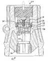
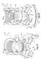
- FIG. 1Adepicts a three-dimensional sectional view of one embodiment of the present invention
- FIG. 1Bdepicts a three-dimensional sectional view of one embodiment of the present invention
- FIG. 2depicts a side sectional view of one embodiment of the present invention
- FIG. 3depicts a side section detail view of a check valve assembly in accordance with one embodiment of the present invention
- FIG. 4depicts a bottom view of a serviceable check valve in accordance with one embodiment of the present invention
- FIG. 5Adepicts a pump stage assembly in accordance with certain embodiments of the present invention
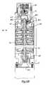
- FIG. 5Bdepicts a side cutaway view of a pump and check valve assembly in accordance with one embodiment of the present invention.
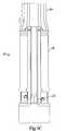
- FIG. 5Cdepicts a side elevation view of a pump and check valve assembly in accordance with one embodiment of the present invention.
- a serviceable check valve 10includes a valve body 12 , a poppet 14 , and a retainer 16 .
- the valve body 12may be made from a variety of materials according to specific service requirements.
- the valve body 12may be fabricated from PVC or stainless steel if particular service requirements specify corrosion resistance.
- the valve body 12may be made from mold injected plastic such as polyethylene or polystyrene.
- the valve body 12may also be machined or cast from a variety of metallic materials such as aluminum or brass.
- the valve body 12includes an inlet 18 and an outlet 20 and may be connected inline with a fluid conduit.
- the fluidmay be liquid, gaseous or a multiphase fluid.
- the valve body 12generally conducts the flow of fluid from the inlet 18 to the outlet 20 .
- the poppet 14engages a valve seat 17 , which may be machined or molded within the retainer 16 or the valve body 12 .
- the valve seat 17may be fastened to the valve body 12 using threads, adhesives or other fastening techniques.
- the valve seat 17may be fabricated from a material that is different from the material of the valve body 12 .
- the check valve assembly 11which includes the poppet 14 and the retainer 16 , may be a one-piece unit or an assembly of parts.
- the poppet 14includes a dome 30 that is attached to a guide 32 by a screw 34 .
- the dome 30may also be attached to the guide 32 by a threaded connection.
- the dome 30 and guide 32may be an integral one-piece part.
- a sealing disc 36is sandwiched between the dome 30 and the guide 32 to seal the poppet 14 against the valve seat 17 . If the sealing disc 36 becomes worn or damaged, the sealing disc 36 may be replaced by removing the dome 30 from the guide 32 .
- the sealing disc 36generally seals against the valve seat 17 , which may inhibit or prevent fluid flow from the outlet 20 to the inlet 18 .
- O-rings, precisely machined surfaces, or other sealing techniques, which will be apparent to those having ordinary skill in valve design,may also be used to seal the poppet 14 against the valve seat 17 .
- a spring 22urges the poppet 14 into the closed position and provides some resistance against fluid flow. If the fluid flow through the valve attempts to reverse, the poppet 14 will seal against the valve seat 17 by a combination of spring resistance and fluid pressure, thereby preventing all or a significant portion of fluid flow back through the valve body 12 .
- the material used to manufacture the poppet 14may be used to aid the seal.
- the poppet 14may be made from a material similar to the valve body 12 or the poppet 14 may be made from dissimilar materials.
- the poppet 14is retained in the valve body 12 by the retainer 16 or other suitable part or combination of parts that can be removed for service of the check valve assembly 11 .
- the retainer 16may have an outside diameter that is larger or equal to the diameter of the poppet 14 .
- the inside diameter of the retainer 16may be smaller than the diameter of the poppet 14 .
- the fluidmay flow through retainer 16 while fluid is flowing through the valve body 12 .
- the retainer 16may prevent the poppet 14 from being displaced from the valve body 12 by fluid pressure.
- vanes 40 and stabilizing ring 42are shown in FIGS. 1–4 . Together, these features can be used in conjunction with a fluid pump, described below, to retain a bearing for support and stabilization of the main shaft of the fluid pump. In designs not developed for use with a particular pump design, vanes 40 and stabilizing ring 42 may be omitted without departing from the spirit and scope of the present invention.
- the retainer 16is retained in the valve body 12 by a threaded connection.
- the retainer 16may engage the valve body 12 with one or more lugs. If lugs are used, the retainer 16 may be removably secured to the valve body 12 using a bayonet lug-type connection. If a threaded connection is used, the valve body 12 and retainer 16 may be left-hand threaded to prevent loosening of the retaining ring by fluid action. If the serviceable check valve 10 is located near a pump, for example, the resulting fluid flow may have a tendency to unscrew a right-hand threaded retainer 16 .
- An O-ring 38may be used to seal the retainer 16 against the valve body 12 and may also provide a frictional interface to prevent inadvertent loosening of the retainer 16 .
- Other systems that allow the retainer 16 to be easily removed from the valve body 12will be apparent to those having ordinary skill in fastener design.
- the check valve assembly 11may be easily serviced or replaced because the retainer 16 is easily removable. Although specialized tools may be used to install the retainer 16 into the valve body 12 , personnel may service the retainer 16 in the field using common tools such as needle-nosed pliers or a screwdriver, for example. One or more lands 24 may be spaced around the retainer 16 to aid in removal or installation of the retainer 16 .
- a toolmay be used to engage the lands 24 and remove the retainer 16 , which will release the poppet 14 from the valve body 12 .
- O-rings or other sealsmay be replaced, the valve seat 17 may be resurfaced or new components may be installed, for example.
- springs 22 having different spring ratesmay be installed to manipulate the action of the poppet 14 according to different applications. For example, a spring 22 having a high rate may be used for high-pressure applications whereas a spring 22 having a low rate may be used for lower pressure applications.
- Other types of springsmay be employed in place of the compression coil type spring 22 shown in FIGS. 1–4 , including but not limited to extension coil springs, elastomer tubes, or Belleville springs.
- a poppet 14 or other valve component that has been damaged by foreign objects flowing in the fluidmay also be easily replaced because of the removable retainer 16 .
- a usermay easily access to the damaged or worn components of the serviceable check valve 10 by unscrewing or detaching the retainer 16 from the valve body 12 .
- the worn or damaged componentsmay be serviced or replaced according to the damage or desired application.
- a serviceable check valve 10may be attached directly to a pump housing of a submersible pump.
- the valve body 12may be attached to a discharge orifice of the pump by a variety of methods such as crimping, welding, clamping or a threaded connection, for example.
- the valve body 12may also be fabricated as an integral part of the pump housing.
- An integral valve body 12may be molded or machined into the discharge orifice of the pump housing.
- An integral valve body 12reduces the likelihood that the connection between the valve body 12 and the pump housing will fail.
- An integral valve body 12may also reduce total production costs by reducing the total number of pieces in a pump system.
- pump and valve assembly 60includes a main shaft 76 driven through coupling 68 by a submersible motor 64 , all disposed within a pump shell 78 .
- the main shaft 76drives one or more pump stage assemblies 50 disposed thereon to move fluid through the pump.
- the end of main shaft 76 distal to the submersible motor 64is supported by a hub sleeve 84 disposed within a bearing 82 , which is disposed within a bearing holder 90 within the body of the check valve 12 .
- the hub sleeveis fastened to main shaft 76 by nut 62 and washer 88 .
- a discharge housing 86is disposed around the check valve 12 .
- Stage assembly 50includes a cup 57 , which holds an eye seal 56 and wear ring 55 .
- Impeller 54is disposed within cup 57 and around main shaft 76 of pump assembly 60 .
- Stage assembly 50further includes a thrust washer 53 , hub seal 52 , and diffuser 51 .
- the serviceable check valve 10may be serviced using common tools, maintenance and repair costs of the pump system are reduced. Maintenance personnel may replace worn or damaged parts of the serviceable check valve 10 rather than replacing an entire check valve assembly 10 .
- the ability to use common tools to service the serviceable check valve 10further enhances efficiency because maintenance personnel are not required to obtain specialized tools. For example, maintenance personnel working on an unrelated system problem may also make unplanned service to the serviceable check valve 10 if they determine that the serviceable check valve 10 is worn or damaged.
Landscapes
- Engineering & Computer Science (AREA)
- General Engineering & Computer Science (AREA)
- Mechanical Engineering (AREA)
- Mining & Mineral Resources (AREA)
- Check Valves (AREA)
Abstract
Description
Claims (14)
Priority Applications (1)
| Application Number | Priority Date | Filing Date | Title |
|---|---|---|---|
| US10/176,885US7036523B2 (en) | 2001-06-22 | 2002-06-21 | Serviceable check valve |
Applications Claiming Priority (2)
| Application Number | Priority Date | Filing Date | Title |
|---|---|---|---|
| US29995501P | 2001-06-22 | 2001-06-22 | |
| US10/176,885US7036523B2 (en) | 2001-06-22 | 2002-06-21 | Serviceable check valve |
Publications (2)
| Publication Number | Publication Date |
|---|---|
| US20020195147A1 US20020195147A1 (en) | 2002-12-26 |
| US7036523B2true US7036523B2 (en) | 2006-05-02 |
Family
ID=26872712
Family Applications (1)
| Application Number | Title | Priority Date | Filing Date |
|---|---|---|---|
| US10/176,885Expired - LifetimeUS7036523B2 (en) | 2001-06-22 | 2002-06-21 | Serviceable check valve |
Country Status (1)
| Country | Link |
|---|---|
| US (1) | US7036523B2 (en) |
Cited By (8)
| Publication number | Priority date | Publication date | Assignee | Title |
|---|---|---|---|---|
| US20090274566A1 (en)* | 2008-04-30 | 2009-11-05 | Itt Manufacturing Enterprises, Inc. | Check valve with plastic lip seal |
| US20170191577A1 (en)* | 2016-01-05 | 2017-07-06 | Strataflo Products, Inc. | Check Valve for Submersible Pump |
| US9885422B2 (en) | 2015-12-15 | 2018-02-06 | International Valve Corporation | Check valve having a friction free replaceable valve insert check assembly |
| US10267428B2 (en) | 2014-10-31 | 2019-04-23 | Strataflo Products, Inc. | Modular check valve |
| US11092257B2 (en) | 2019-04-10 | 2021-08-17 | Cnb Marine Solutions Llc | Serviceable valve carousel system |
| USD954207S1 (en)* | 2019-07-03 | 2022-06-07 | Cnb Marine Solutions Llc | Valve carousel |
| US20220412469A1 (en)* | 2021-06-25 | 2022-12-29 | Hutchinson | Fluidic connection device and non-return insert valve for vehicles |
| US20250180124A1 (en)* | 2022-04-04 | 2025-06-05 | Weir Minerals Netherlands B.V. | Valve |
Families Citing this family (8)
| Publication number | Priority date | Publication date | Assignee | Title |
|---|---|---|---|---|
| DE102006013667A1 (en)* | 2006-03-24 | 2007-09-27 | Robert Bosch Gmbh | Thermal deburring system with quick exhaust |
| CN102486238B (en)* | 2010-12-06 | 2013-06-12 | 东辉休闲运动用品(上海)有限公司 | One-way valve |
| WO2013033160A1 (en)* | 2011-08-31 | 2013-03-07 | The Subsea Company | Plug and pressure testing method and apparatus |
| ITRM20110150U1 (en)* | 2011-10-03 | 2013-04-04 | Etatron D S Spa | BOTTOM FILTER EQUIPPED WITH SPRING IN PVDF PLASTIC MATERIAL, USED AS AN ACCESSORY OF ELECTROMECHANICAL DOSING PUMPS. |
| CN103603974B (en)* | 2013-11-07 | 2015-08-26 | 市下控股有限公司 | Anti-siphon pressurized one-way valve |
| EP3156661B1 (en)* | 2015-10-15 | 2023-12-06 | Grundfos Holding A/S | Domestic water system or pump with a check valve |
| US11313482B2 (en)* | 2019-11-14 | 2022-04-26 | Entegris, Inc. | Welded check valve |
| US11434900B1 (en)* | 2022-04-25 | 2022-09-06 | Vulcan Industrial Holdings, LLC | Spring controlling valve |
Citations (42)
| Publication number | Priority date | Publication date | Assignee | Title |
|---|---|---|---|---|
| US1615811A (en)* | 1923-11-05 | 1927-01-25 | Louis M Pearce | Back-pressure valve |
| US1659478A (en)* | 1927-07-19 | 1928-02-14 | Lee J Black | Combined guide plug and float valve for well casings |
| US2034790A (en) | 1933-04-24 | 1936-03-24 | Reda Pump Company | Pipe line pump unit |
| US2930397A (en)* | 1957-04-08 | 1960-03-29 | Aeroquip Corp | Pressure fill limiter, thermo relief and dump valve for pressurized vessels |
| US3001546A (en)* | 1958-10-06 | 1961-09-26 | Clifford A Salisbury | Check valve |
| US3037458A (en) | 1957-04-15 | 1962-06-05 | Goulds Pumps | Glass pump |
| US3111961A (en)* | 1959-04-27 | 1963-11-26 | John E Dudgcon | Removable spring check valve |
| US3518021A (en) | 1968-04-04 | 1970-06-30 | Gen Electric | Thrust bearing for compressor |
| US3542057A (en)* | 1968-11-04 | 1970-11-24 | Louis T Staiano | Drain plug valve for sumps |
| US3891001A (en)* | 1973-12-14 | 1975-06-24 | Irlin H Botnick | Shutoff valve with cleanout filter |
| US3904211A (en) | 1973-12-03 | 1975-09-09 | Gen Motors Corp | Rotary face seal |
| US3914072A (en) | 1974-11-19 | 1975-10-21 | Weil Mclain Company Inc | Fluid pumping assembly |
| US3926443A (en) | 1974-03-05 | 1975-12-16 | Coors Porcelain Co | Composite seal ring and assembly |
| US4037985A (en) | 1976-05-20 | 1977-07-26 | Worthington Pump, Inc. | Flushing liquid system for the wearing ring in centrifugal pumps and the wearing ring assembly and wearing ring for use therein |
| US4063846A (en) | 1974-11-13 | 1977-12-20 | Borg-Warner Corporation | Pump impeller improvement |
| US4099890A (en) | 1975-08-21 | 1978-07-11 | Mitsui Mining & Smelting Co., Ltd. | Impeller type pump having seal means and protective means |
| US4129144A (en)* | 1976-11-16 | 1978-12-12 | Bo Allan Andersson | Stabilizing check valve |
| US4152096A (en) | 1975-08-21 | 1979-05-01 | Mitsui Mining & Smelting Co., Ltd. | Pump having seal means and protective means |
| US4172690A (en) | 1976-04-29 | 1979-10-30 | Klein, Schanzlin & Becker Aktiengesellschaft | Arrangement for centering the impellers in a multi-stage centrifugal pump |
| US4215714A (en)* | 1978-06-01 | 1980-08-05 | Laue Charles E | Valve and method of making |
| US4245952A (en) | 1979-05-10 | 1981-01-20 | Hale Fire Pump Company | Pump |
| US4257443A (en)* | 1978-12-15 | 1981-03-24 | Victor Equipment Company | Check valve |
| US4281839A (en) | 1979-04-16 | 1981-08-04 | Purex Corporation | Rotary face sealing apparatus |
| US4410188A (en) | 1982-11-17 | 1983-10-18 | Copes John C | Slurry pump double mechanical split face seal |
| US4422469A (en)* | 1981-08-12 | 1983-12-27 | The Marley/Wylain Company | Submersible pump check valve |
| US4511307A (en) | 1983-09-02 | 1985-04-16 | Dresser Industries, Inc. | Centrifugal pump |
| US4572056A (en) | 1981-06-03 | 1986-02-25 | Saphirwerk Industrieprodukte Ag | Plunger or floating piston pump |
| US4655684A (en) | 1984-08-02 | 1987-04-07 | Haentjens Walter D | Centrifugal pump for wide range of operating conditions |
| US4664595A (en) | 1983-09-30 | 1987-05-12 | Ebara Corporation | Combination of slide members |
| US4746269A (en) | 1986-05-22 | 1988-05-24 | Jacuzzi Inc. | Seal cooling for plastic pumps |
| US4768923A (en) | 1987-06-09 | 1988-09-06 | General Motors Corporation | Combined water pump, bearing and seal assembly |
| US4824123A (en) | 1988-03-31 | 1989-04-25 | Smith International, Inc. | Mechanical face seal for rock bits |
| US4826396A (en) | 1988-01-29 | 1989-05-02 | The United States Of America As Represented By The Administrator Of The National Aeronautics And Space Administration | Rotor self-lubricating axial stop |
| US4871297A (en) | 1987-04-08 | 1989-10-03 | Westinghouse Electric Corp. | Reactor coolant pump sealing surfaces with titanium nitride coating |
| US4872808A (en) | 1987-06-22 | 1989-10-10 | Oil Dynamics, Inc. | Centrifugal pump modular bearing support for pumping fluids containing abrasive particles |
| US4884945A (en) | 1988-07-21 | 1989-12-05 | John Crane, Inc. | Dynamic seal arrangement for impeller pump |
| US4909705A (en) | 1987-12-18 | 1990-03-20 | Hitachi, Ltd. | Multi-stage diffuse-type centrifugal pump |
| US4909707A (en) | 1989-02-14 | 1990-03-20 | Itt Corporation | Centrifugal pump and floating casing ring therefor |
| US4913619A (en) | 1988-08-08 | 1990-04-03 | Barrett Haentjens & Co. | Centrifugal pump having resistant components |
| US4971093A (en)* | 1990-02-13 | 1990-11-20 | Andersson Bo A | Check valve |
| US5133639A (en) | 1991-03-19 | 1992-07-28 | Sta-Rite Industries, Inc. | Bearing arrangement for centrifugal pump |
| US6129338A (en)* | 1997-12-30 | 2000-10-10 | Golan; Ilan Z. | Motorcycle fuel system petcock valve |
- 2002
- 2002-06-21USUS10/176,885patent/US7036523B2/ennot_activeExpired - Lifetime
Patent Citations (42)
| Publication number | Priority date | Publication date | Assignee | Title |
|---|---|---|---|---|
| US1615811A (en)* | 1923-11-05 | 1927-01-25 | Louis M Pearce | Back-pressure valve |
| US1659478A (en)* | 1927-07-19 | 1928-02-14 | Lee J Black | Combined guide plug and float valve for well casings |
| US2034790A (en) | 1933-04-24 | 1936-03-24 | Reda Pump Company | Pipe line pump unit |
| US2930397A (en)* | 1957-04-08 | 1960-03-29 | Aeroquip Corp | Pressure fill limiter, thermo relief and dump valve for pressurized vessels |
| US3037458A (en) | 1957-04-15 | 1962-06-05 | Goulds Pumps | Glass pump |
| US3001546A (en)* | 1958-10-06 | 1961-09-26 | Clifford A Salisbury | Check valve |
| US3111961A (en)* | 1959-04-27 | 1963-11-26 | John E Dudgcon | Removable spring check valve |
| US3518021A (en) | 1968-04-04 | 1970-06-30 | Gen Electric | Thrust bearing for compressor |
| US3542057A (en)* | 1968-11-04 | 1970-11-24 | Louis T Staiano | Drain plug valve for sumps |
| US3904211A (en) | 1973-12-03 | 1975-09-09 | Gen Motors Corp | Rotary face seal |
| US3891001A (en)* | 1973-12-14 | 1975-06-24 | Irlin H Botnick | Shutoff valve with cleanout filter |
| US3926443A (en) | 1974-03-05 | 1975-12-16 | Coors Porcelain Co | Composite seal ring and assembly |
| US4063846A (en) | 1974-11-13 | 1977-12-20 | Borg-Warner Corporation | Pump impeller improvement |
| US3914072A (en) | 1974-11-19 | 1975-10-21 | Weil Mclain Company Inc | Fluid pumping assembly |
| US4099890A (en) | 1975-08-21 | 1978-07-11 | Mitsui Mining & Smelting Co., Ltd. | Impeller type pump having seal means and protective means |
| US4152096A (en) | 1975-08-21 | 1979-05-01 | Mitsui Mining & Smelting Co., Ltd. | Pump having seal means and protective means |
| US4172690A (en) | 1976-04-29 | 1979-10-30 | Klein, Schanzlin & Becker Aktiengesellschaft | Arrangement for centering the impellers in a multi-stage centrifugal pump |
| US4037985A (en) | 1976-05-20 | 1977-07-26 | Worthington Pump, Inc. | Flushing liquid system for the wearing ring in centrifugal pumps and the wearing ring assembly and wearing ring for use therein |
| US4129144A (en)* | 1976-11-16 | 1978-12-12 | Bo Allan Andersson | Stabilizing check valve |
| US4215714A (en)* | 1978-06-01 | 1980-08-05 | Laue Charles E | Valve and method of making |
| US4257443A (en)* | 1978-12-15 | 1981-03-24 | Victor Equipment Company | Check valve |
| US4281839A (en) | 1979-04-16 | 1981-08-04 | Purex Corporation | Rotary face sealing apparatus |
| US4245952A (en) | 1979-05-10 | 1981-01-20 | Hale Fire Pump Company | Pump |
| US4572056A (en) | 1981-06-03 | 1986-02-25 | Saphirwerk Industrieprodukte Ag | Plunger or floating piston pump |
| US4422469A (en)* | 1981-08-12 | 1983-12-27 | The Marley/Wylain Company | Submersible pump check valve |
| US4410188A (en) | 1982-11-17 | 1983-10-18 | Copes John C | Slurry pump double mechanical split face seal |
| US4511307A (en) | 1983-09-02 | 1985-04-16 | Dresser Industries, Inc. | Centrifugal pump |
| US4664595A (en) | 1983-09-30 | 1987-05-12 | Ebara Corporation | Combination of slide members |
| US4655684A (en) | 1984-08-02 | 1987-04-07 | Haentjens Walter D | Centrifugal pump for wide range of operating conditions |
| US4746269A (en) | 1986-05-22 | 1988-05-24 | Jacuzzi Inc. | Seal cooling for plastic pumps |
| US4871297A (en) | 1987-04-08 | 1989-10-03 | Westinghouse Electric Corp. | Reactor coolant pump sealing surfaces with titanium nitride coating |
| US4768923A (en) | 1987-06-09 | 1988-09-06 | General Motors Corporation | Combined water pump, bearing and seal assembly |
| US4872808A (en) | 1987-06-22 | 1989-10-10 | Oil Dynamics, Inc. | Centrifugal pump modular bearing support for pumping fluids containing abrasive particles |
| US4909705A (en) | 1987-12-18 | 1990-03-20 | Hitachi, Ltd. | Multi-stage diffuse-type centrifugal pump |
| US4826396A (en) | 1988-01-29 | 1989-05-02 | The United States Of America As Represented By The Administrator Of The National Aeronautics And Space Administration | Rotor self-lubricating axial stop |
| US4824123A (en) | 1988-03-31 | 1989-04-25 | Smith International, Inc. | Mechanical face seal for rock bits |
| US4884945A (en) | 1988-07-21 | 1989-12-05 | John Crane, Inc. | Dynamic seal arrangement for impeller pump |
| US4913619A (en) | 1988-08-08 | 1990-04-03 | Barrett Haentjens & Co. | Centrifugal pump having resistant components |
| US4909707A (en) | 1989-02-14 | 1990-03-20 | Itt Corporation | Centrifugal pump and floating casing ring therefor |
| US4971093A (en)* | 1990-02-13 | 1990-11-20 | Andersson Bo A | Check valve |
| US5133639A (en) | 1991-03-19 | 1992-07-28 | Sta-Rite Industries, Inc. | Bearing arrangement for centrifugal pump |
| US6129338A (en)* | 1997-12-30 | 2000-10-10 | Golan; Ilan Z. | Motorcycle fuel system petcock valve |
Cited By (10)
| Publication number | Priority date | Publication date | Assignee | Title |
|---|---|---|---|---|
| US20090274566A1 (en)* | 2008-04-30 | 2009-11-05 | Itt Manufacturing Enterprises, Inc. | Check valve with plastic lip seal |
| US10267428B2 (en) | 2014-10-31 | 2019-04-23 | Strataflo Products, Inc. | Modular check valve |
| US9885422B2 (en) | 2015-12-15 | 2018-02-06 | International Valve Corporation | Check valve having a friction free replaceable valve insert check assembly |
| US20170191577A1 (en)* | 2016-01-05 | 2017-07-06 | Strataflo Products, Inc. | Check Valve for Submersible Pump |
| US11092257B2 (en) | 2019-04-10 | 2021-08-17 | Cnb Marine Solutions Llc | Serviceable valve carousel system |
| US11536387B2 (en) | 2019-04-10 | 2022-12-27 | Cnb Marine Solutions Llc | Serviceable valve carousel system |
| USD954207S1 (en)* | 2019-07-03 | 2022-06-07 | Cnb Marine Solutions Llc | Valve carousel |
| US20220412469A1 (en)* | 2021-06-25 | 2022-12-29 | Hutchinson | Fluidic connection device and non-return insert valve for vehicles |
| US11946568B2 (en)* | 2021-06-25 | 2024-04-02 | Hutchinson | Fluidic connection device and non-return insert valve for vehicles |
| US20250180124A1 (en)* | 2022-04-04 | 2025-06-05 | Weir Minerals Netherlands B.V. | Valve |
Also Published As
| Publication number | Publication date |
|---|---|
| US20020195147A1 (en) | 2002-12-26 |
Similar Documents
| Publication | Publication Date | Title |
|---|---|---|
| US7036523B2 (en) | Serviceable check valve | |
| US10502333B2 (en) | Ball valve with components integrated into the ball member | |
| US5575424A (en) | Vacuum breaker for faucets | |
| US5174327A (en) | In-line check valve | |
| US7048001B2 (en) | Pressure regulator with single strut regulator seat | |
| US10267428B2 (en) | Modular check valve | |
| EP2140184B1 (en) | Quick change check valve system | |
| US20110108146A1 (en) | Flow Restricted Seat Ring for Pressure Regulators | |
| US20070284296A1 (en) | Filter cartridge and head assembly with internal shutoff valve | |
| CA2901751C (en) | Main valve with internal rigid structure | |
| US10738901B1 (en) | Check valve | |
| US5143117A (en) | Break away check valve | |
| US5409042A (en) | Constant-rate flow control valve | |
| EP0537665A2 (en) | Check valve | |
| US20060021659A1 (en) | Hose adapter incorporating a valve and a method of manufacturing the same | |
| MX2008004568A (en) | Valve for control of high pressure air pulse. | |
| ZA200403870B (en) | Reverse pulse cleaning of filter elements | |
| US7261117B2 (en) | Diverter valve assembly | |
| NL1008826C2 (en) | Fluid valve. | |
| US20170191577A1 (en) | Check Valve for Submersible Pump | |
| WO1995007424A1 (en) | A gas container valve | |
| US3226079A (en) | Swivel ring valve | |
| US8511640B2 (en) | Ball valve with detachable slide bearing bushes | |
| CN210240673U (en) | One-way valve | |
| RU2315172C1 (en) | Intra-flange check valve for injection wellhead fittings |
Legal Events
| Date | Code | Title | Description |
|---|---|---|---|
| AS | Assignment | Owner name:JBD, INC., ARKANSAS Free format text:ASSIGNMENT OF ASSIGNORS INTEREST;ASSIGNORS:NIXON, KENNETH;VOLK, JAMES;REEL/FRAME:014992/0377 Effective date:20040727 | |
| AS | Assignment | Owner name:FRANKLIN PUMP SYSTEMS, INC., ARKANSAS Free format text:ASSIGNMENT OF ASSIGNORS INTEREST;ASSIGNOR:JBD INC.;REEL/FRAME:015252/0390 Effective date:20040729 | |
| STCF | Information on status: patent grant | Free format text:PATENTED CASE | |
| FPAY | Fee payment | Year of fee payment:4 | |
| FEPP | Fee payment procedure | Free format text:PAYER NUMBER DE-ASSIGNED (ORIGINAL EVENT CODE: RMPN); ENTITY STATUS OF PATENT OWNER: LARGE ENTITY Free format text:PAYOR NUMBER ASSIGNED (ORIGINAL EVENT CODE: ASPN); ENTITY STATUS OF PATENT OWNER: LARGE ENTITY | |
| FPAY | Fee payment | Year of fee payment:8 | |
| MAFP | Maintenance fee payment | Free format text:PAYMENT OF MAINTENANCE FEE, 12TH YEAR, LARGE ENTITY (ORIGINAL EVENT CODE: M1553) Year of fee payment:12 | |
| AS | Assignment | Owner name:FRANKLIN ELECTRIC CO., INC., INDIANA Free format text:ASSIGNMENT OF ASSIGNORS INTEREST;ASSIGNOR:HEADWATER COMPANIES, LLC;REEL/FRAME:051024/0869 Effective date:20191115 Owner name:HEADWATER COMPANIES, LLC, INDIANA Free format text:MERGER AND CHANGE OF NAME;ASSIGNORS:FRANKLIN ELECTRIC SALES, INC.;FRANKLIN PUMP SYSTEMS, INC.;HEADWATER COMPANIES, LLC;REEL/FRAME:051040/0576 Effective date:20071221 |