US7035544B1 - Identification of related communications channels in a wavelength division multiplexed optical network - Google Patents
Identification of related communications channels in a wavelength division multiplexed optical networkDownload PDFInfo
- Publication number
- US7035544B1 US7035544B1US10/033,430US3343001AUS7035544B1US 7035544 B1US7035544 B1US 7035544B1US 3343001 AUS3343001 AUS 3343001AUS 7035544 B1US7035544 B1US 7035544B1
- Authority
- US
- United States
- Prior art keywords
- channels
- optical
- signal characteristics
- optical signals
- computer
- Prior art date
- Legal status (The legal status is an assumption and is not a legal conclusion. Google has not performed a legal analysis and makes no representation as to the accuracy of the status listed.)
- Expired - Lifetime, expires
Links
Images


Classifications
- H—ELECTRICITY
- H04—ELECTRIC COMMUNICATION TECHNIQUE
- H04J—MULTIPLEX COMMUNICATION
- H04J14/00—Optical multiplex systems
- H04J14/02—Wavelength-division multiplex systems
- H04J14/0227—Operation, administration, maintenance or provisioning [OAMP] of WDM networks, e.g. media access, routing or wavelength allocation
- H04J14/0241—Wavelength allocation for communications one-to-one, e.g. unicasting wavelengths
- H—ELECTRICITY
- H04—ELECTRIC COMMUNICATION TECHNIQUE
- H04J—MULTIPLEX COMMUNICATION
- H04J14/00—Optical multiplex systems
- H04J14/02—Wavelength-division multiplex systems
- H04J14/0278—WDM optical network architectures
- H04J14/028—WDM bus architectures
Definitions
- This inventionrelates generally to wavelength division multiplexed optical networks, and more particularly to identifying related communication channels in such a network.
- each WDM optical fibercan contain multiple channels, each on a different wavelength.
- WDM optical fibercan be dense groupings of different channels, from as few as two or three up to several hundred. The different densities separate the different channels by wavelengths, called channel spacing. The closer the channel spacing, the more difficult and expensive it is to distinguish the channels in the fiber.
- WDM optical networksare typically full duplex, either using two fibers carrying light waves in opposite directions, or a single fiber carrying light waves in both directions.
- the fiber(s)must be separated into the individual channels so that the data inside the channels can be intercepted and analyzed. Additionally, the two channels corresponding to a single conversation may need to be identified because they generally are not carried on the same wavelength in both directions.
- Channels in an optical network that carry optical signalsare evaluated using signal characteristics and suitable channels are compared to identify the channels that represent a single conversation using matching criteria. In another aspect, only channels that carry optical signals representing conversations of interest are compared.
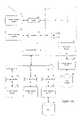
- FIG. 1is a diagram illustrating the operations of an embodiment of the invention
- FIGS. 2A–Dare flowcharts of methods that perform the operations of the embodiment of the invention shown in FIG. 1 ;
- FIG. 3Ais a diagram of one embodiment of an operating environment suitable for practicing the present invention.
- FIG. 3Bis a diagram of one embodiment of a computer system suitable for use in the operating environment of FIG. 3A .
- a WDM (Wavelength Division Multiplexing) scanner 100identifies matching channel pairs within two optical fibers.
- the operations of the WDM scanner 100may be configured through input parameters 157 , such as channel ranges, framing types, encoded formats, protocol markers, number of pairs (e.g., first, all, a particular subset) to detect, designated conversations, matching criteria, among other values, that are set by an outside user, application, network device, or other entity, represented in FIG. 1 as a network management device 155 .
- the WDM scanner 100can be set with default values that subsequently may be changed by the network management device 155 to tailor the scanner 100 to particular network situations.
- the network management device 155may be a protocol analyzer, a network analyzer, a network monitor, or a security device, such as a firewall.
- the matched pairsare output to the management device 155 for subsequent monitoring and/or analysis, including intrusion detection, protocol troubleshooting, and traffic load monitoring.
- the control logicis distinguished from the optical signals by line width in FIG. 1 , with the optical signals being represented by heavier lines.
- Optical signals 101 from fiber Aare fed into an optical tap 103 that diverts a portion of the signals for input into a tunable optical wavelength filter 105 .
- the optical tap 103may be an in-line optical splitter, an optical amplifier with an access port, or an optical regenerator, among other devices.
- An optical signal analyzer 109instructs 115 the filter 105 to select a particular channel 107 . If the optical signal in the selected channel 107 is of insufficient quality, such as having a signal-to-noise ratio that is too low, the analyzer 109 discards the channel and requests the next channel from the filter 105 . Assuming the quality of the optical signal is acceptable, the analyzer 109 determines which, if any, of the characteristics of the channel it is configured to recognize.
- the configuration parameters of the analyzer 109may be set by the network management device 155 and include characteristics such as speed, framing type, and encoding format.
- the analyzer 109records the results of its analysis of the channel in a data store 113 , such as a database.
- a data store 113such as a database.
- the scanner 100similarly analyzes the channels in fiber B using optical tap 123 , tunable optical wavelength filter 153 , optical signal analyzer 129 and data store 133 as shown in FIG. 1 .
- the operations of optical signal analyzers 109 , 129may be driven by the input parameters 157 .
- a matcher 141retrieves 143, 145 the information from the data stores 113 , 133 and determines which channels contain optical signals that are suitable based on the requirements of the network management device 155 .
- an unsuitable optical signalmay have an unusable speed, may represent an unrecognizable framing type, or be encoded in a format that cannot be handled by the network management device 155 .
- the matcher 141instructs 147 , 149 each filter 105 , 125 to select a suitable channel 151 , 153 from the fibers for evaluation.
- the matcher 141determines if the two selected channels contain the data flows for a single “conversation” using various communication tags or markers within the optical signals as matching criteria.
- TCPtransport communications protocol
- the matching criteriamay be configurable and is generally specified by the network management device 155 or other entity controlling the operation of the scanner 100 . It will be appreciated that the markers may be at any of the protocol layers defined by the OSI (Open Systems Interconnection) network model up to, and including, the application layer.
- OSIOpen Systems Interconnection
- the matcherrecords the match in the data stores 113 , 133 and instructs 143 , 149 filters 105 , 125 to select new suitable channels for matching. If the selected channels do not match, the matcher 141 instructs 149 filter 125 to select another unmatched channel from fiber B. If no channels in fiber B match the selected channel in fiber A, the matcher 141 instructs 147 filter 105 to select another channel in fiber A and attempts to the match unmatched channels in fiber B against the newly selected channel in fiber A When all channels in fiber A have been evaluated by the matcher 141 , the scanner 100 terminates the current session.
- the matching pairs 159may be output as they are found or may all be output at one time when the current session terminates.
- the scanner 100may output information from the data stores 113 , 133 about the matching pairs 159 or about the channels in general.
- the matching pairs 159may undergo additional processing before being output to the network management device 155 , such as wavelength or protocol conversion, or a change in signal type, e.g., optical to electrical.
- FIG. 1shows the operations for matching only two fibers but the invention is not so limited and one of skill in the art will recognize that the invention can be expanded to match channels in any number of fibers.
- the scanner 100may analyze the fibers in parallel. Selection of the first fiber (“fiber A”) to process may be random, determined by input parameters 157 , or based on other criteria.
- the network management device 155designates only certain conversations as of interest and suitable channels containing data flows for other conversations are ignored by the matcher 141 .
- the detection of the channels containing data flows of such designated conversationsis made by matcher 141 based on the type of analysis to be subsequently performed on the matching pairs. For example, if a particular protocol is to be analyzed, the matcher 141 uses protocol information recorded in the data stores 113 , 133 to determine which channels to select for evaluation.
- the WDM scanner 100has been described as a discrete system, one of skill in the art will immediately understand that the operations of the WDM scanner 100 may be incorporated into the network management device 155 . Furthermore, although a particular arrangement of components for the WDM scanner 100 are shown in FIG. 1 , one of skill will immediately recognize that the operations may be embodied in different arrangements of components without departing from the scope of the invention.
- the analyzers 109 , 129may be the same optical signal analyzer.
- the optical signal analyzer(s)also may be co-located with the matcher 141 .
- the filters that select channels for the analyzers 109 , 129may be different components than the filters that select channels for the matcher 141 .
- FIG. 2Aone embodiment of an identification method 200 that performs the operations described above in conjunction with FIG. 1 is illustrated in FIG. 2A .
- the method 200accesses a fiber, extracts the channel signals (block 201 ), and selects a channel with acceptable quality (block 203 ).
- the method 200analyzes the selected channel and records the characteristics of the optical signal in the channel in the database (block 205 ) as described in more detail in conjunction with FIG. 2B . If there are more channels in the current fiber (block 207 ), the method 200 returns to block 203 to select another channel for analysis. If all channels in the current fiber have been evaluated, and the current fiber is the not the final fiber to be analyzed (block 209 ), the method 200 returns to block 201 to access the next fiber.
- the method 200When the method 200 has processed all the channels in the fibers through the operations represented by blocks 201 until block 207 , the method 200 performs a matching operation (block 211 ) as described in more detail in conjunction with FIGS. 2C–D to determine the channel pairs that will be sent to the subsequent monitoring and/or analysis process.
- the matching operation at block 211may operate in parallel with the operations in blocks 201 through 209 to evaluate channels that already have been analyzed.
- FIGS. 2B–Dmay constitute computer programs made up of machine-executable instructions. Describing the methods by reference to a flowchart enables one skilled in the art to develop such programs including such instructions to carry out the methods on suitably configured computers (the processor of the computer executing the instructions from computer-readable media), such as described in conjunction with FIG. 3B further below.
- the instructionsmay also execute on individual processors or controllers implemented as either stand-alone machines or integrated into other components or devices, such as a network management device.
- the machine-executable instructionsmay be written in a computer programming language or may be embodied in firmware logic. If written in a programming language conforming to a recognized standard, such instructions can be executed on a variety of hardware platforms and for interface to a variety of operating systems.
- the present inventionis not described with reference to any particular programming language. It will be appreciated that a variety of programming languages may be used to implement the teachings of the invention as described herein.
- an “analyze signal” method 205determines if the characteristics of the optical signal in a channel are recognizable by comparing the signal against its configuration parameters (block 213 ). As described previously, the configuration parameters may be specified by the subsequent monitoring and/or analysis process. If the signal satisfies the parameters (block 215 ), the channel is marked as suitable in the data store (block 217 ); otherwise, it is marked as unsuitable (block 219 ). The characteristics, or the fact that they cannot be recognized, also may be written to the data base at blocks 217 , 219 .
- a match method 211obtains information about a suitable channel from fiber A (block 221 ) and performs a matching loop (represented by blocks 223 until 233 ) on the optical signal in the channel.
- Information about a suitable channel from fiber Bis obtained (block 225 ) and matching criteria is used to determine if the optical signals in the channels form a single conversation (block 227 ). If so, the matching channel pair is output, or recorded for subsequent output, to the subsequent monitoring and/or analysis process (block 229 ). If additional possible matches for the channel in fiber A are desired (block 230 ), the method 211 returns to block 225 to search for another matching channel in fiber B; otherwise the matching loop ends at block 233 . If there are still unmatched channels in fiber A (block 235 ), the method 211 obtains another suitable channel from fiber A at block 221 and repeats the matching loop.
- FIG. 2DDetails of one embodiment of the process represented at blocks 221 and 225 are illustrated in FIG. 2D as a “get suitable channel” method 240 .
- the method 240examines the data rate (block 241 ), the bit pattern (block 245 ), and the encoding (block 249 ) recorded in the database for the optical signal in each channel (repeating at block 255 ) until it finds a channel having characteristics appropriate for the subsequent monitoring and/or analysis process (blocks 243 , 247 , 251 ).
- the method 240also can determine if the optical signal contains a conversation designed as “of interest” by the network management device (block 253 ). If the optical signal meets the specified characteristics, the channel information is returned to the match method 211 .
- FIGS. 2A–Dare not required to be performed in the particular order shown and that the processes of the invention may be divided into more or fewer logical blocks than those shown.
- alternate embodiments of the method 240may evaluate more or fewer, or different, characteristics than illustrated without departing from the scope of the invention.
- other operations in FIG. 2Amay be implemented as machine-executable instructions although not illustrated as such herein.
- FIGS. 3A–BThe following description of FIGS. 3A–B is intended to provide an overview of computer hardware and other operating components in which the invention may be practiced, but is not intended to limit the applicable environments.
- One of skill in the artwill immediately appreciate that the invention can be practiced with other computer system configurations, including hand-held devices, multiprocessor systems, microprocessor-based or programmable consumer electronics, network PCs, minicomputers, mainframe computers, and the like.
- the inventioncan also be practiced in distributed computing environments where tasks are performed by remote processing devices that are linked through a communications network having a physical or wireless infrastructure, or a combination of both.
- FIG. 3Ashows several computer systems that are coupled together through a network 3 , such as the Internet.
- the term “Internet” as used hereinrefers to a network of networks which uses certain protocols, such as the TCP/IP protocol, and possibly other protocols such as the hypertext transfer protocol (HTTP) for hypertext markup language (HTML) documents that make up the World Wide Web (web).
- HTTPhypertext transfer protocol
- HTMLhypertext markup language
- the physical connections of the Internet and the protocols and communication procedures of the Internetare well known to those of skill in the art.
- Access to the Internet 3is typically provided by Internet service providers (ISP), such as the ISPs 5 and 7 .
- ISPInternet service providers
- client computer systems 21 , 25 , 35 , and 37obtain access to the Internet through the Internet service providers, such as ISPs 5 and 7 , through either physical or wireless interfaces.
- Access to the Internetallows users of the client computer systems to exchange information, receive and send e-mails, and view documents, such as documents which have been prepared in the HTML format.
- These documentsare often provided by web servers, such as web server 9 which is considered to be “on” the Internet.
- web serversare provided by the ISPs, such as ISP 5 , although a computer system can be set up and connected to the Internet without that system being also an ISP as is well known in the art.
- the web server 9is typically at least one computer system which operates as a server computer system and is configured to operate with the protocols of the World Wide Web and is coupled to the Internet.
- the web server 9can be part of an ISP which provides access to the Internet for client systems.
- the web server 9is shown coupled to the server computer system 11 which itself is coupled to web content 10 , which can be considered a form of a media database. It will be appreciated that while two computer systems 9 and 11 are shown in FIG. 4A , the web server system 9 and the server computer system 11 can be one computer system having different software components providing the web server functionality and the server functionality provided by the server computer system 11 which will be described further below.
- Client computer systems 21 , 25 , 35 , and 37can each, with the appropriate web browsing software, view HTML pages provided by the web server 9 .
- the ISP 5provides Internet connectivity to the client computer system 21 through the modem interface 23 which can be considered part of the client computer system 21 .
- the client computer systemcan be a personal computer system, a network computer, a Web TV system, a handheld wireless device, or other such computer system.
- the ISP 7provides Internet connectivity for client systems 25 , 35 , and 37 , although as shown in FIG. 4A , the connections are not the same for these three computer systems.
- Client computer system 25is coupled through a modem interface 27 while client computer systems 35 and 37 are part of a LAN. While FIG.
- FIG. 4Ashows the interfaces 23 and 27 as generically as a “modem,” it will be appreciated that each of these interfaces can be an analog modem, ISDN modem, cable modem, satellite transmission interface (e.g. “Direct PC”), radio frequency (RF), cellular, or other interfaces for coupling a computer system to other computer systems.
- Client computer systems 35 and 37are coupled to a LAN 33 through network interfaces 39 and 41 , which can be Ethernet network or other network interfaces.
- the LAN 33is also coupled to a gateway computer system 31 which can provide firewall and other Internet related services for the local area network.
- This gateway computer system 31is coupled to the ISP 7 to provide Internet connectivity to the client computer systems 35 and 37 .
- the gateway computer system 31can be a conventional server computer system.
- the web server system 9can be a conventional server computer system.
- a server computer system 43can be directly coupled to the LAN 33 through a network interface 45 to provide files 47 and other services to the clients 35 , 37 , without the need to connect to the Internet through the gateway system 31 .
- FIG. 3Bshows one example of a conventional computer system that can be used as a client computer system or a server computer system or as a web server system in conjunction with the present invention. It will also be appreciated that such a computer system can be used to perform many of the functions of an Internet service provider, such as ISP 5 .
- the computer system 51interfaces to external systems through the modem or network interface 53 . It will be appreciated that the modem or network interface 53 can be considered to be part of the computer system 51 .
- This interface 53can be an analog modem, ISDN modem, cable modem, token ring interface, satellite transmission interface (e.g. “Direct PC”), radio frequency (RF), cellular, or other interfaces for coupling a computer system to other computer systems.
- RFradio frequency
- the computer system 51includes a processing unit 55 , which can be a conventional microprocessor such as an Intel Pentium microprocessor or Motorola Power PC microprocessor.
- Memory 59is coupled to the processor 55 by a bus 57 .
- Memory 59can be dynamic random access memory (DRAM) and can also include static RAM (SRAM).
- the bus 57couples the processor 55 to the memory 59 and also to non-volatile storage 65 and to display controller 61 and to the input/output (I/O) controller 67 .
- the display controller 61controls in the conventional manner a display on a display device 63 which can be a cathode ray tube (CRT) or liquid crystal display.
- CTRcathode ray tube
- the input/output devices 69can include a keyboard, disk drives, printers, a scanner, and other input and output devices, including a mouse or other pointing device.
- the display controller 61 and the I/O controller 67can be implemented with conventional well known technology.
- a digital image input device 71can be a digital camera which is coupled to an I/O controller 67 in order to allow images from the digital camera to be input into the computer system 51 .
- the non-volatile storage 65is often a magnetic hard disk, an optical disk, or another form of storage for large amounts of data. Some of this data is often written, by a direct memory access process, into memory 59 during execution of software in the computer system 51 .
- machine-readable mediumincludes any type of storage device that is accessible by the processor 55 and also encompasses a carrier wave that encodes a data signal.
- the computer system 51is one example of many possible computer systems which have different architectures.
- personal computers based on an Intel microprocessoroften have multiple buses, one of which can be an input/output (I/O) bus for the peripherals and one that directly connects the processor 55 and the memory 59 (often referred to as a memory bus).
- the busesare connected together through bridge components that perform any necessary translation due to differing bus protocols.
- Network computersare another type of computer system that can be used with the present invention.
- Network computersdo not usually include a hard disk or other mass storage, and the executable programs are loaded from a network connection into the memory 59 for execution by the processor 55 .
- a Web TV systemwhich is known in the art, is also considered to be a computer system according to the present invention, but it may lack some of the features shown in FIG. 3B , such as certain input or output devices.
- a typical computer systemwill usually include at least a processor, memory, and a bus coupling the memory to the processor.
- the computer system 51is controlled by operating system software which includes a file management system, such as a disk operating system, which is part of the operating system software.
- a file management systemsuch as a disk operating system
- One example of an operating system software with its associated file management system softwareis the family of operating systems known as Windows® from Microsoft Corporation of Redmond, Wash., and their associated file management systems.
- the file management systemis typically stored in the non-volatile storage 65 and causes the processor 55 to execute the various acts required by the operating system to input and output data and to store data in memory, including storing files on the non-volatile storage 65
Landscapes
- Engineering & Computer Science (AREA)
- Computer Networks & Wireless Communication (AREA)
- Signal Processing (AREA)
- Data Exchanges In Wide-Area Networks (AREA)
Abstract
Description
Claims (29)
Priority Applications (1)
| Application Number | Priority Date | Filing Date | Title |
|---|---|---|---|
| US10/033,430US7035544B1 (en) | 2001-12-27 | 2001-12-27 | Identification of related communications channels in a wavelength division multiplexed optical network |
Applications Claiming Priority (1)
| Application Number | Priority Date | Filing Date | Title |
|---|---|---|---|
| US10/033,430US7035544B1 (en) | 2001-12-27 | 2001-12-27 | Identification of related communications channels in a wavelength division multiplexed optical network |
Publications (1)
| Publication Number | Publication Date |
|---|---|
| US7035544B1true US7035544B1 (en) | 2006-04-25 |
Family
ID=36191122
Family Applications (1)
| Application Number | Title | Priority Date | Filing Date |
|---|---|---|---|
| US10/033,430Expired - LifetimeUS7035544B1 (en) | 2001-12-27 | 2001-12-27 | Identification of related communications channels in a wavelength division multiplexed optical network |
Country Status (1)
| Country | Link |
|---|---|
| US (1) | US7035544B1 (en) |
Cited By (17)
| Publication number | Priority date | Publication date | Assignee | Title |
|---|---|---|---|---|
| US20040120710A1 (en)* | 2002-12-09 | 2004-06-24 | Nabil Seddigh | Method and system for light path monitoring in an optical communication network |
| US20080080862A1 (en)* | 2006-10-02 | 2008-04-03 | Huawei Technologies Co., Ltd. | Optical Identification Demodulation Method and System |
| US20100104283A1 (en)* | 2007-02-01 | 2010-04-29 | Eci Telecom Ltd | Technique for managing optical networks |
| US7792427B1 (en) | 2006-01-30 | 2010-09-07 | Lockheed Martin Corporation | Optical code division multiple access data storage and retrieval |
| US7903973B1 (en) | 2005-12-23 | 2011-03-08 | Lockheed Martin Corporation | Dynamic temporal duration optical transmission privacy |
| US7991288B1 (en)* | 2006-02-07 | 2011-08-02 | Lockheed Martin Corporation | Optical code division multiple access data storage encryption and retrieval |
| US8984644B2 (en) | 2003-07-01 | 2015-03-17 | Securityprofiling, Llc | Anti-vulnerability system, method, and computer program product |
| US9100431B2 (en) | 2003-07-01 | 2015-08-04 | Securityprofiling, Llc | Computer program product and apparatus for multi-path remediation |
| US9118710B2 (en) | 2003-07-01 | 2015-08-25 | Securityprofiling, Llc | System, method, and computer program product for reporting an occurrence in different manners |
| US9118709B2 (en) | 2003-07-01 | 2015-08-25 | Securityprofiling, Llc | Anti-vulnerability system, method, and computer program product |
| US9118708B2 (en) | 2003-07-01 | 2015-08-25 | Securityprofiling, Llc | Multi-path remediation |
| US9117069B2 (en) | 2003-07-01 | 2015-08-25 | Securityprofiling, Llc | Real-time vulnerability monitoring |
| US9118711B2 (en) | 2003-07-01 | 2015-08-25 | Securityprofiling, Llc | Anti-vulnerability system, method, and computer program product |
| US9350752B2 (en) | 2003-07-01 | 2016-05-24 | Securityprofiling, Llc | Anti-vulnerability system, method, and computer program product |
| US9407643B1 (en)* | 2004-08-03 | 2016-08-02 | Spirent Communications, Inc. | System and method for consolidating network streams for network analysis |
| US20180191434A1 (en)* | 2017-01-04 | 2018-07-05 | Viavi Solutions Inc. | Wavelength identification and analysis sensor |
| US10270526B2 (en)* | 2016-11-07 | 2019-04-23 | Electronics And Telecommunications Research Institute | Apparatus and method for monitoring status of terminal |
Citations (8)
| Publication number | Priority date | Publication date | Assignee | Title |
|---|---|---|---|---|
| US5130836A (en)* | 1990-06-01 | 1992-07-14 | Japan Aviation Electronics Industry Limited | Optical transceiver |
| US5572515A (en) | 1994-12-28 | 1996-11-05 | Tektronix, Inc. | Sonet/SDH signal recognition and selection |
| EP0911994A2 (en) | 1997-10-22 | 1999-04-28 | Nortel Networks Corporation | Optical signal power detection with signature bit pattern in WDM systems |
| US5986782A (en)* | 1997-05-29 | 1999-11-16 | Ciena Corporation | Signal-to-noise monitoring in WDM optical communication systems |
| WO1999067609A1 (en) | 1998-06-23 | 1999-12-29 | Ditech Corporation | Optical network monitor |
| WO2000025451A1 (en) | 1998-10-23 | 2000-05-04 | Koninklijke Kpn N.V. | Method and apparatus for monitoring an optical wdm network |
| US20020024692A1 (en)* | 2000-08-30 | 2002-02-28 | Nec Corporation | Optical transmission system, monitoring method therefor, optical communication apparatus, and optical external conducting apparatus |
| US20040202171A1 (en)* | 2000-11-27 | 2004-10-14 | Daisuke Hama | Network and edge router |
- 2001
- 2001-12-27USUS10/033,430patent/US7035544B1/ennot_activeExpired - Lifetime
Patent Citations (8)
| Publication number | Priority date | Publication date | Assignee | Title |
|---|---|---|---|---|
| US5130836A (en)* | 1990-06-01 | 1992-07-14 | Japan Aviation Electronics Industry Limited | Optical transceiver |
| US5572515A (en) | 1994-12-28 | 1996-11-05 | Tektronix, Inc. | Sonet/SDH signal recognition and selection |
| US5986782A (en)* | 1997-05-29 | 1999-11-16 | Ciena Corporation | Signal-to-noise monitoring in WDM optical communication systems |
| EP0911994A2 (en) | 1997-10-22 | 1999-04-28 | Nortel Networks Corporation | Optical signal power detection with signature bit pattern in WDM systems |
| WO1999067609A1 (en) | 1998-06-23 | 1999-12-29 | Ditech Corporation | Optical network monitor |
| WO2000025451A1 (en) | 1998-10-23 | 2000-05-04 | Koninklijke Kpn N.V. | Method and apparatus for monitoring an optical wdm network |
| US20020024692A1 (en)* | 2000-08-30 | 2002-02-28 | Nec Corporation | Optical transmission system, monitoring method therefor, optical communication apparatus, and optical external conducting apparatus |
| US20040202171A1 (en)* | 2000-11-27 | 2004-10-14 | Daisuke Hama | Network and edge router |
Non-Patent Citations (7)
| Title |
|---|
| DIGL Press Release, Digital Lightwave Introduces Industry's First Integrated Portable DWDM Analyzer, Digital Lightwave, Thursday, May 18, 2000, 2 pages, http://www.lightwave.com/newspress/051700rls.htm. |
| HP Press Release, SuperComm '99: HP Launches Dedicated DWDM Test Solution, System Maximizes Throughput and Economy of Test for Network Equipment Manufacturers, Atlanta, Supercomm'99, Jun. 8, 3 pages. |
| Launching the Q8384 Optical Spectrum Analyzer For Evaluating Next Generation Optical Communications Systems And Components/With a 10pm Wavelength Resolution and 60dB Dymanic Range, Perfectly Suited for DWDM Optical Communications, Advantest Corporation Press Release, Jul. 7, 1999, 2 pages, http://www.www.advantest.co.jp/99-7-7-e.html. |
| MN9320A Optical Channel Drop Unit, BER Testing 10 Gbps, 50GHz Spacing ±20 pm Accuracy, Independent Test Access Tool for Comprehensive DWDM Measurements, Anritsu, 8 pages. |
| OSA-155 DWDM System Analyzer, Spectrum and WDM parameter analysis for applications on DWDM systems, Wavetech Wandel Goltermann, 1999, 5 pages http://fiberoptics.wwgsolutions.com/produccts/osa/osa155.html. |
| Test & Measurement News Lightwave, Agilent Technologies Test & Measurement Online News & Events, Agilent SpectraBER testers handle 10-Gb/s, 2.5-Gb/s, 622-Mb/s, and 155-Mb/s rates, DWDM and SONET/SDH functional test to 10 Gb/s, Feb. 2000, Issue 60, 2 pages, http://www.tm.agilent.com/tmo/TMNews/English/17-0002.html. |
| Test & Measurement News Lightwave, Agilent Technologies Test & Measurement Online News & Events, Get complete, reliable test capability for DWDM system installation and maintenance, Characterize DWDM systems in the field, Nov. 1999, Issue 59, 2 pages, http://www.tm.agilent.com/tmo/TMNews/English/02-9911.htm. |
Cited By (27)
| Publication number | Priority date | Publication date | Assignee | Title |
|---|---|---|---|---|
| US7529480B2 (en)* | 2002-12-09 | 2009-05-05 | Alcatel-Lucent Canada Inc. | Method and system for light path monitoring in an optical communication network |
| US20040120710A1 (en)* | 2002-12-09 | 2004-06-24 | Nabil Seddigh | Method and system for light path monitoring in an optical communication network |
| US8984644B2 (en) | 2003-07-01 | 2015-03-17 | Securityprofiling, Llc | Anti-vulnerability system, method, and computer program product |
| US9100431B2 (en) | 2003-07-01 | 2015-08-04 | Securityprofiling, Llc | Computer program product and apparatus for multi-path remediation |
| US10050988B2 (en) | 2003-07-01 | 2018-08-14 | Securityprofiling, Llc | Computer program product and apparatus for multi-path remediation |
| US10021124B2 (en) | 2003-07-01 | 2018-07-10 | Securityprofiling, Llc | Computer program product and apparatus for multi-path remediation |
| US10154055B2 (en) | 2003-07-01 | 2018-12-11 | Securityprofiling, Llc | Real-time vulnerability monitoring |
| US9225686B2 (en) | 2003-07-01 | 2015-12-29 | Securityprofiling, Llc | Anti-vulnerability system, method, and computer program product |
| US9350752B2 (en) | 2003-07-01 | 2016-05-24 | Securityprofiling, Llc | Anti-vulnerability system, method, and computer program product |
| US10104110B2 (en) | 2003-07-01 | 2018-10-16 | Securityprofiling, Llc | Anti-vulnerability system, method, and computer program product |
| US9118710B2 (en) | 2003-07-01 | 2015-08-25 | Securityprofiling, Llc | System, method, and computer program product for reporting an occurrence in different manners |
| US9118709B2 (en) | 2003-07-01 | 2015-08-25 | Securityprofiling, Llc | Anti-vulnerability system, method, and computer program product |
| US9118708B2 (en) | 2003-07-01 | 2015-08-25 | Securityprofiling, Llc | Multi-path remediation |
| US9117069B2 (en) | 2003-07-01 | 2015-08-25 | Securityprofiling, Llc | Real-time vulnerability monitoring |
| US9118711B2 (en) | 2003-07-01 | 2015-08-25 | Securityprofiling, Llc | Anti-vulnerability system, method, and computer program product |
| US9407643B1 (en)* | 2004-08-03 | 2016-08-02 | Spirent Communications, Inc. | System and method for consolidating network streams for network analysis |
| US7903973B1 (en) | 2005-12-23 | 2011-03-08 | Lockheed Martin Corporation | Dynamic temporal duration optical transmission privacy |
| US7792427B1 (en) | 2006-01-30 | 2010-09-07 | Lockheed Martin Corporation | Optical code division multiple access data storage and retrieval |
| US7991288B1 (en)* | 2006-02-07 | 2011-08-02 | Lockheed Martin Corporation | Optical code division multiple access data storage encryption and retrieval |
| US7603034B2 (en)* | 2006-10-02 | 2009-10-13 | Huawei Technologies Co., Ltd. | Optical identification demodulation method and system |
| US20080080862A1 (en)* | 2006-10-02 | 2008-04-03 | Huawei Technologies Co., Ltd. | Optical Identification Demodulation Method and System |
| US20100104283A1 (en)* | 2007-02-01 | 2010-04-29 | Eci Telecom Ltd | Technique for managing optical networks |
| US10270526B2 (en)* | 2016-11-07 | 2019-04-23 | Electronics And Telecommunications Research Institute | Apparatus and method for monitoring status of terminal |
| US20180191434A1 (en)* | 2017-01-04 | 2018-07-05 | Viavi Solutions Inc. | Wavelength identification and analysis sensor |
| US10181900B2 (en)* | 2017-01-04 | 2019-01-15 | Viavi Solutions Inc. | Wavelength identification and analysis sensor |
| US10425157B2 (en) | 2017-01-04 | 2019-09-24 | Viavi Solutions Inc. | Wavelength identification and analysis sensor |
| US10637571B2 (en) | 2017-01-04 | 2020-04-28 | Viavi Solutions Inc. | Wavelength identification and analysis sensor |
Similar Documents
| Publication | Publication Date | Title |
|---|---|---|
| US7035544B1 (en) | Identification of related communications channels in a wavelength division multiplexed optical network | |
| US8639752B2 (en) | Systems and methods for content type classification | |
| US8171150B2 (en) | Data transfer system and method | |
| US8095683B2 (en) | Method and system for mirroring dropped packets | |
| US6757727B1 (en) | Top-down network analysis system and method with adaptive filtering capabilities | |
| US7979543B2 (en) | Systems and methods for categorizing network traffic content | |
| KR100472202B1 (en) | Web collaborative browsing system and method with using IRC protocol | |
| US6415321B1 (en) | Domain mapping method and system | |
| US8745198B2 (en) | Method for discovery and troubleshooting of network application usage and performance issues | |
| US20050060425A1 (en) | Application-based autonomic connectivity | |
| US20080144655A1 (en) | Systems, methods, and computer program products for passively transforming internet protocol (IP) network traffic | |
| KR100424724B1 (en) | Apparatus for detecting invasion with network stream analysis | |
| US10802937B2 (en) | High order layer intrusion detection using neural networks | |
| JP2001312484A (en) | Method and system for fast web server selection | |
| US20130311549A1 (en) | Framework for service personalization | |
| US20030084340A1 (en) | System and method of graphically displaying data for an intrusion protection system | |
| US20100290353A1 (en) | Apparatus and method for classifying network packet data | |
| US20080062989A1 (en) | Smart match search method for captured data frames | |
| US6954785B1 (en) | System for identifying servers on network by determining devices that have the highest total volume data transfer and communication with at least a threshold number of client devices | |
| US20070214242A1 (en) | Network configuration change evaluation program, network configuration change evaluation device, and network configuration change evaluation method | |
| US7546339B2 (en) | Client-server apparatus and method using alternative-response protocols | |
| KR101344398B1 (en) | Router and method for application awareness and traffic control on flow based router | |
| US20080235370A1 (en) | Method and System for Controlling Network Traffic of P2P and Instant Messenger Softwares | |
| Dubin et al. | Video quality representation classification of encrypted http adaptive video streaming. | |
| US7103675B1 (en) | Multiplexed request and reply packets |
Legal Events
| Date | Code | Title | Description |
|---|---|---|---|
| AS | Assignment | Owner name:NETWORKS ASSOCIATES TECHNOLOGY, INC., CALIFORNIA Free format text:ASSIGNMENT OF ASSIGNORS INTEREST;ASSIGNOR:WON, KING L.;REEL/FRAME:012424/0693 Effective date:20011226 | |
| AS | Assignment | Owner name:MCAFEE, INC.,CALIFORNIA Free format text:MERGER;ASSIGNOR:NETWORKS ASSOCIATES TECHNOLOGY, INC.;REEL/FRAME:016646/0513 Effective date:20041119 Owner name:MCAFEE, INC., CALIFORNIA Free format text:MERGER;ASSIGNOR:NETWORKS ASSOCIATES TECHNOLOGY, INC.;REEL/FRAME:016646/0513 Effective date:20041119 | |
| STCF | Information on status: patent grant | Free format text:PATENTED CASE | |
| FPAY | Fee payment | Year of fee payment:4 | |
| FEPP | Fee payment procedure | Free format text:PAYOR NUMBER ASSIGNED (ORIGINAL EVENT CODE: ASPN); ENTITY STATUS OF PATENT OWNER: LARGE ENTITY | |
| FPAY | Fee payment | Year of fee payment:8 | |
| FEPP | Fee payment procedure | Free format text:PAYER NUMBER DE-ASSIGNED (ORIGINAL EVENT CODE: RMPN); ENTITY STATUS OF PATENT OWNER: LARGE ENTITY Free format text:PAYOR NUMBER ASSIGNED (ORIGINAL EVENT CODE: ASPN); ENTITY STATUS OF PATENT OWNER: LARGE ENTITY | |
| AS | Assignment | Owner name:MCAFEE, LLC, CALIFORNIA Free format text:CHANGE OF NAME AND ENTITY CONVERSION;ASSIGNOR:MCAFEE, INC.;REEL/FRAME:043665/0918 Effective date:20161220 | |
| MAFP | Maintenance fee payment | Free format text:PAYMENT OF MAINTENANCE FEE, 12TH YEAR, LARGE ENTITY (ORIGINAL EVENT CODE: M1553) Year of fee payment:12 | |
| AS | Assignment | Owner name:MORGAN STANLEY SENIOR FUNDING, INC., MARYLAND Free format text:SECURITY INTEREST;ASSIGNOR:MCAFEE, LLC;REEL/FRAME:045056/0676 Effective date:20170929 Owner name:JPMORGAN CHASE BANK, N.A., NEW YORK Free format text:SECURITY INTEREST;ASSIGNOR:MCAFEE, LLC;REEL/FRAME:045055/0786 Effective date:20170929 | |
| AS | Assignment | Owner name:MORGAN STANLEY SENIOR FUNDING, INC., MARYLAND Free format text:CORRECTIVE ASSIGNMENT TO CORRECT THE REMOVE PATENT 6336186 PREVIOUSLY RECORDED ON REEL 045056 FRAME 0676. ASSIGNOR(S) HEREBY CONFIRMS THE SECURITY INTEREST;ASSIGNOR:MCAFEE, LLC;REEL/FRAME:054206/0593 Effective date:20170929 Owner name:JPMORGAN CHASE BANK, N.A., NEW YORK Free format text:CORRECTIVE ASSIGNMENT TO CORRECT THE REMOVE PATENT 6336186 PREVIOUSLY RECORDED ON REEL 045055 FRAME 786. ASSIGNOR(S) HEREBY CONFIRMS THE SECURITY INTEREST;ASSIGNOR:MCAFEE, LLC;REEL/FRAME:055854/0047 Effective date:20170929 | |
| AS | Assignment | Owner name:MCAFEE, LLC, CALIFORNIA Free format text:RELEASE OF INTELLECTUAL PROPERTY COLLATERAL - REEL/FRAME 045055/0786;ASSIGNOR:JPMORGAN CHASE BANK, N.A., AS COLLATERAL AGENT;REEL/FRAME:054238/0001 Effective date:20201026 | |
| AS | Assignment | Owner name:MCAFEE, LLC, CALIFORNIA Free format text:RELEASE OF INTELLECTUAL PROPERTY COLLATERAL - REEL/FRAME 045056/0676;ASSIGNOR:MORGAN STANLEY SENIOR FUNDING, INC., AS COLLATERAL AGENT;REEL/FRAME:059354/0213 Effective date:20220301 | |
| AS | Assignment | Owner name:JPMORGAN CHASE BANK, N.A., AS ADMINISTRATIVE AGENT AND COLLATERAL AGENT, NEW YORK Free format text:SECURITY INTEREST;ASSIGNOR:MCAFEE, LLC;REEL/FRAME:059354/0335 Effective date:20220301 | |
| AS | Assignment | Owner name:JPMORGAN CHASE BANK, N.A., AS ADMINISTRATIVE AGENT, NEW YORK Free format text:CORRECTIVE ASSIGNMENT TO CORRECT THE THE PATENT TITLES AND REMOVE DUPLICATES IN THE SCHEDULE PREVIOUSLY RECORDED AT REEL: 059354 FRAME: 0335. ASSIGNOR(S) HEREBY CONFIRMS THE ASSIGNMENT;ASSIGNOR:MCAFEE, LLC;REEL/FRAME:060792/0307 Effective date:20220301 |