US7035512B2 - Method for providing a broadband infrastructure in a building by means of optical fibers - Google Patents
Method for providing a broadband infrastructure in a building by means of optical fibersDownload PDFInfo
- Publication number
- US7035512B2 US7035512B2US10/471,506US47150604AUS7035512B2US 7035512 B2US7035512 B2US 7035512B2US 47150604 AUS47150604 AUS 47150604AUS 7035512 B2US7035512 B2US 7035512B2
- Authority
- US
- United States
- Prior art keywords
- optical
- electric wires
- conduits
- building
- terminal
- Prior art date
- Legal status (The legal status is an assumption and is not a legal conclusion. Google has not performed a legal analysis and makes no representation as to the accuracy of the status listed.)
- Expired - Lifetime
Links
- 239000013307optical fiberSubstances0.000titleclaimsabstractdescription37
- 238000000034methodMethods0.000titleclaimsabstractdescription16
- 230000003287optical effectEffects0.000claimsabstractdescription54
- 230000005540biological transmissionEffects0.000claimsabstractdescription5
- 238000012546transferMethods0.000claimsdescription5
- 238000012545processingMethods0.000abstractdescription8
- 238000012544monitoring processMethods0.000abstractdescription4
- 239000000835fiberSubstances0.000description7
- 230000005611electricityEffects0.000description5
- 238000006243chemical reactionMethods0.000description3
- 238000009434installationMethods0.000description3
- 238000004891communicationMethods0.000description2
- 238000013461designMethods0.000description2
- 230000003321amplificationEffects0.000description1
- 238000010276constructionMethods0.000description1
- 238000010616electrical installationMethods0.000description1
- 239000000383hazardous chemicalSubstances0.000description1
- 231100000206health hazardToxicity0.000description1
- 238000012423maintenanceMethods0.000description1
- 238000003199nucleic acid amplification methodMethods0.000description1
- 239000013589supplementSubstances0.000description1
- 230000002195synergetic effectEffects0.000description1
Images


Classifications
- G—PHYSICS
- G02—OPTICS
- G02B—OPTICAL ELEMENTS, SYSTEMS OR APPARATUS
- G02B6/00—Light guides; Structural details of arrangements comprising light guides and other optical elements, e.g. couplings
- G02B6/46—Processes or apparatus adapted for installing or repairing optical fibres or optical cables
- G02B6/47—Installation in buildings
- G02B6/475—Mechanical aspects of installing cables in ducts or the like for buildings
- H—ELECTRICITY
- H04—ELECTRIC COMMUNICATION TECHNIQUE
- H04B—TRANSMISSION
- H04B10/00—Transmission systems employing electromagnetic waves other than radio-waves, e.g. infrared, visible or ultraviolet light, or employing corpuscular radiation, e.g. quantum communication
- H04B10/11—Arrangements specific to free-space transmission, i.e. transmission through air or vacuum
- H04B10/114—Indoor or close-range type systems
- H04B10/1149—Arrangements for indoor wireless networking of information
- H—ELECTRICITY
- H04—ELECTRIC COMMUNICATION TECHNIQUE
- H04B—TRANSMISSION
- H04B10/00—Transmission systems employing electromagnetic waves other than radio-waves, e.g. infrared, visible or ultraviolet light, or employing corpuscular radiation, e.g. quantum communication
- H04B10/25—Arrangements specific to fibre transmission
Definitions
- the inventionrelates to a method for providing a broadband infrastructure in a building by means of optical fibres for the transmission of optical signals, which building is provided with a system of conduits for ducting electric wires for the transfer of electric energy.
- the inventionfurther relates to a system for the transmission of optical signals via optical fibers in a building, which building is provided with a system of conduits for enveloping electric wires for the transfer of electric energy.
- FTTOFibre To The Office
- FTTHFiber To The Home
- increase of the number of PCs etc. and increase of broadband applications (Internet, multimedia, etc.) for application in offices and private situationsinduce a need for the application of optical fibres within buildings, houses, etc.
- the object of the present inventionis to provide a method and system for installing and maintaining a network of optical fibres throughout the building without special constructional interventions.
- the inventionis applicable in both new and existing buildings.
- the electric wires and optical fibreswill preferably be pushed, pulled or blown simultaneously into the conduits.
- the optical fibresif possible, will be added to the wiring already present. Where this is not possible, the electric wiring will possibly have to be removed first to be subsequently re-introduced together with the optical fibre(s) to be added.
- the design of an in-house networkbased on this method (use of fibre), it is also possible to project paths that do not run through electric conduits (for instance plastic fibre along a skirting-board).
- the fibresare fitted to the same terminals as those to which the electric wires are fitted, so that those terminals, the wall sockets and light connections, at the same time serve as interface to and from the PCs etc.
- the system of the inventionpreferably comprises wall or ceiling terminals to which both the electric wires and the optical fibres are fitted.
- the terminalscan comprise one or more connectors to which an optical fibre is fitted and to which a matching counter-connector can be connected.
- a PCor other information processor—can be connected with the optical home network and, via that optical network, with PCs etc. in the rest of the house or the building or, via an interface, with a public network.
- the terminalscan comprise an optical transceiver to which an optical fiber is fitted.
- An optical transceiveris herein understood to mean an element by which the light signals (e.g.
- infraredsupplied by the optical fiber are optically radiated to its surroundings and by which, in the opposite direction, light signals can be received and presented to the optical fiber.
- the transmitter and receiver, respectively, of the wall/ceiling terminalcan comprise—as known per se—an optical lens and/or an optical reflector. Since the optical fibers are fitted to the same terminals as those to which the electric wires have been fitted, this combination affords a synergetic possibility of providing the terminals with electrically supplied amplification means for amplifying the optical signals.
- the terminalscan comprise electrically supplied conversion means for converting the optical signals transmitted and received, respectively, via those terminals.
- the conversion meanscan convert the optical signals to electrical signals and vice versa, with the electrical signals being presented to, or taken from, electrical connectors which are comprised by the terminals and to which a matching counter-connector can be connected.
- This O/E converter incorporated into the terminalaffords the possibility of connecting PCs in the electric domain with the—optical—home network and with each other.
- the terminalcan comprise processing or routing means for processing and/or routing the signals transferred via the optical fibres.
- processing or routing meanstoo can be simply supplied, in the terminal, from the electricity grid.
- the electric wires per building, or per section of the buildingmeet in a central unit—switchboard—for monitoring and/or controlling the electric energy transferred via the electric wires, in the building or section thereof.
- the systemalso comprises a central element for monitoring, processing and/or controlling the information transferred via the optical fibres, in the building or section thereof.
- Such central elementcan be formed, for instance, by a central computer or home network server, which, at the central location also accommodating the electric switchboard and possibly the telecommunication connection (the “meter cupboard”), can then be formed integrally with the other facilities, electricity, telecommunication.
- a central computer or home network serverwhich, at the central location also accommodating the electric switchboard and possibly the telecommunication connection (the “meter cupboard”), can then be formed integrally with the other facilities, electricity, telecommunication.
- Such an arrangementalso affords practical possibilities of “telemetering” electricity, gas, etc.
- the present methodcan be seen as a supplement to other methods for laying out an in-house infrastructure.
- the methodis cheaper than installing a separate conduit system.
- this methoddoes not involve any risk of interference and disturbance of other equipment (e.g. in hospitals) or possible health hazards of radio waves.
- the use of light signalse.g. infrared
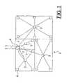
- FIG. 1schematically depicts a conduit system of a conventional electrical installation in a building in which the present invention can be incorporated;
- FIG. 2depicts ceiling terminal 5 which utilizes the teachings of the present invention
- FIG. 3depicts wall terminal 6 which also utilizes the teachings of the present invention
- FIG. 4depicts a second embodiment of inventive wall terminal 6 ;
- FIG. 5depicts a third embodiment of inventive wall terminal 6 ;
- FIG. 6depicts a fourth embodiment of inventive wall terminal 6 .
- FIG. 7depicts a further elaboration of central power point 4 shown in FIG. 1 .
- FIG. 1schematically shows a conduit system of a conventional electric installation in a building 1 .
- the building 1is connected via cables 2 and 3 to the public electricity grid and communication/media network, respectively.
- the latter networkcomprises an optical fibre (“Fibre To The Office”(FTTO) and “Fibre To The Home”(FTTH)) enabling broadband transmission.
- FTTOFiber To The Office
- FTTHFiber To The Home
- the central junction box 5constitutes a base terminal for connecting lighting fixtures etc. and for further distributing the electric energy in the room, via conduits passing to different wall sockets 6 and any further ceiling outlets, for further lighting fixtures.
- Through the conduits 7pass electric wires 8 (see FIG. 2 ) which have been pulled, pushed or blown into the conduits.
- the optical fibres 10are ducted from the distribution point 4 through the same conduits 7 as the electric wires. Further, the optical fibres are fitted to the same ceiling outlets 5 and wall outlets 6 as those to which the electric wires are fitted.
- the terminalsare understood to be constituted by the wall and ceiling outlets 5 and 6 , possibly along with any components connected therewith, such as (lighting) fixtures, wall sockets, switches, etc.
- the terminals 5 and 6which, accordingly, may or may not —depending on specific designs that may be given to them by different manufacturers—comprise components mounted thereon or thereto.
- FIG. 2shows a ceiling terminal 5 .
- the electric wires 8are supplied, which, with the aid of wire connectors 9 , are connected to each other and to, for instance, a lighting fixture.
- the conduits 7also duct optical fibers 10 , which have preferably been pulled into the conduits together with the electric wires.
- the optical fibrescan be connected to each other and to an optical transceiver (transmitter/receiver) 11 .
- the transceiver 11normally comprises a lens, sometimes a reflector, with which, on the one hand, IR light signals supplied by the optical fibre are radiated to the respective space, and with which, on the other hand, IR light signals from, for instance, equipment disposed in that space are received.
- the terminal 5comprises an IR port, known per se.
- FIG. 3shows a wall terminal 6 , to which the electric wires 8 and optical fibre 10 supplied through the conduit 7 are connected, that is, the fibre 10 to an optical transceiver 11 and the wires 8 to an electrical wall plug 12 .
- FIG. 4shows the same wall terminal 6 , though with the optical transceiver 11 replaced by an optical connector 13 to which the optical fiber 10 is fitted and to which a PC etc. can be connected via a matching counter-connector 14 and an optical cable 15 .
- FIG. 5shows the same wall terminal 6 , provided with a transceiver 11 , but additionally provided with a built-in electrically supplied optical amplifier 16 , for amplifying the optical signals exchanged via the transceiver 11 .
- the amplifier 16is supplied from the electricity grid via electric supply wires 8 a .
- FIG. 6shows a wall terminal 6 , provided with an electrical connector 23 to which a PC etc. can be connected via a matching counter-connector 24 and an electric cable 25 .
- E/O converter 26By installing an E/O converter 26 , PCs etc. which do not possess an optical interface can still communicate via the optical home network.
- modules 16 and 26 showninstead of the modules 16 and 26 shown, other—electrically supplied—modules can be installed in the terminals 5 or 6 , for instance processing or routing modules (“domestic routers”) for processing and/or routing the signals transferred via the optical fibres.
- FIG. 7shows a further elaboration of the central power point 4 shown in FIG. 1 .
- the electric wires 8 located within conduits 7meet in a central element 17 —the central switchboard—where the electric energy distributed via the electric wires in the building, in particular power consumption and safety (earth leakage etc.), is monitored.
- a central element 18which monitors, processes and/or controls the optical signals to and from the building 1 via the optical cable 3 .
- the central elementcan comprise, for instance, a central home computer or home server via which telecommunication, multimedia exchange (internet, video, etc.) with the outside world proceed and which, on the other hand, provides for network management etc within the building.
- the telecommunication sectioncan be concentrated in a telecommunication home exchange 19 .
- the optical fibres 10 of the home networkare connected via a connection module 20 to the housing of the electrical switchboard 17 , such that the optical fibers 10 , together with the electric wires 8 , can be ducted via the conduits 7 to the different terminals 5 and 6 in the building, where they can be connected to the different PCs etc., via the IR transceivers 11 and the connectors 13 , 23 , 14 , 24 , respectively.
Landscapes
- Engineering & Computer Science (AREA)
- Physics & Mathematics (AREA)
- Electromagnetism (AREA)
- Structural Engineering (AREA)
- Civil Engineering (AREA)
- Computer Networks & Wireless Communication (AREA)
- Signal Processing (AREA)
- General Physics & Mathematics (AREA)
- Optics & Photonics (AREA)
- Computing Systems (AREA)
- Selective Calling Equipment (AREA)
- Optical Communication System (AREA)
- Light Guides In General And Applications Therefor (AREA)
Abstract
Description
The invention relates to a method for providing a broadband infrastructure in a building by means of optical fibres for the transmission of optical signals, which building is provided with a system of conduits for ducting electric wires for the transfer of electric energy.
The invention further relates to a system for the transmission of optical signals via optical fibers in a building, which building is provided with a system of conduits for enveloping electric wires for the transfer of electric energy.
“Fibre To The Office” (FTTO) and “Fibre To The Home” (FTTH), increase of the number of PCs etc. and increase of broadband applications (Internet, multimedia, etc.) for application in offices and private situations induce a need for the application of optical fibres within buildings, houses, etc. In house-construction, normally no special facilities—cable ducts, etc.—are provided for the installation and maintenance of a computer network. The object of the present invention is to provide a method and system for installing and maintaining a network of optical fibres throughout the building without special constructional interventions. The invention is applicable in both new and existing buildings.
According to the invention, it is presently proposed to duct the optical fibres through the same conduits as the wires of the electric installation. In new houses to be built, the electric wires and optical fibres will preferably be pushed, pulled or blown simultaneously into the conduits. In existing houses —where the electric wires have already been installed—the optical fibres, if possible, will be added to the wiring already present. Where this is not possible, the electric wiring will possibly have to be removed first to be subsequently re-introduced together with the optical fibre(s) to be added. In the design of an in-house network based on this method (use of fibre), it is also possible to project paths that do not run through electric conduits (for instance plastic fibre along a skirting-board).
Preferably, the fibres are fitted to the same terminals as those to which the electric wires are fitted, so that those terminals, the wall sockets and light connections, at the same time serve as interface to and from the PCs etc. In the system according to the invention, therefore, the fibres—after installation—are enveloped by the same conduits as the electric wires.
Accordingly, the system of the invention preferably comprises wall or ceiling terminals to which both the electric wires and the optical fibres are fitted. The terminals can comprise one or more connectors to which an optical fibre is fitted and to which a matching counter-connector can be connected. In this way, a PC—or other information processor—can be connected with the optical home network and, via that optical network, with PCs etc. in the rest of the house or the building or, via an interface, with a public network. Another option is for the terminals to comprise an optical transceiver to which an optical fiber is fitted. An optical transceiver is herein understood to mean an element by which the light signals (e.g. infrared) supplied by the optical fiber are optically radiated to its surroundings and by which, in the opposite direction, light signals can be received and presented to the optical fiber. Communication with the PCs etc. in the space where the terminals are, proceeds in a noncontact manner via optical (IR) transmitters and receivers in the PCs etc. The transmitter and receiver, respectively, of the wall/ceiling terminal can comprise—as known per se—an optical lens and/or an optical reflector. Since the optical fibers are fitted to the same terminals as those to which the electric wires have been fitted, this combination affords a synergetic possibility of providing the terminals with electrically supplied amplification means for amplifying the optical signals.
If it is necessary to convert the optical signals in any way, that possibility is also afforded by the terminals. Thus, the terminals can comprise electrically supplied conversion means for converting the optical signals transmitted and received, respectively, via those terminals. Thus, it is possible for the conversion means to convert the optical signals to electrical signals and vice versa, with the electrical signals being presented to, or taken from, electrical connectors which are comprised by the terminals and to which a matching counter-connector can be connected. This O/E converter incorporated into the terminal affords the possibility of connecting PCs in the electric domain with the—optical—home network and with each other.
Also, the terminal can comprise processing or routing means for processing and/or routing the signals transferred via the optical fibres. Such processing or routing means too can be simply supplied, in the terminal, from the electricity grid. Normally, the electric wires per building, or per section of the building, meet in a central unit—switchboard—for monitoring and/or controlling the electric energy transferred via the electric wires, in the building or section thereof. As a logical extension of the system according to the invention, the system also comprises a central element for monitoring, processing and/or controlling the information transferred via the optical fibres, in the building or section thereof. Such central element can be formed, for instance, by a central computer or home network server, which, at the central location also accommodating the electric switchboard and possibly the telecommunication connection (the “meter cupboard”), can then be formed integrally with the other facilities, electricity, telecommunication. Such an arrangement also affords practical possibilities of “telemetering” electricity, gas, etc.
The present method can be seen as a supplement to other methods for laying out an in-house infrastructure. The method is cheaper than installing a separate conduit system. Compared with the use of radio waves, this method does not involve any risk of interference and disturbance of other equipment (e.g. in hospitals) or possible health hazards of radio waves. The use of light signals (e.g. infrared) can be limited to specific spaces, which can be an advantage.
The teachings of the present invention can be readily understood by considering the following detailed description in conjunction with the accompanying drawings, in which:
To facilitate understanding, identical reference numerals have been used, where possible, to designate identical elements that are common to the figures.
According to the invention, theoptical fibres 10 are ducted from thedistribution point 4 through thesame conduits 7 as the electric wires. Further, the optical fibres are fitted to thesame ceiling outlets 5 andwall outlets 6 as those to which the electric wires are fitted. It is noted that the terminals are understood to be constituted by the wall andceiling outlets terminals
Claims (13)
1. A method for providing broadband infrastructure in a building by using optical fibers for transmission of optical signals, the building being provided with conduits for ducting electric wires, the electrical wires to be used to transfer electric energy, wherein the optical fibers are ducted through the same conduits as the electric wires; the method comprising the steps of:
fitting a plurality of the electric wires in one of said conduits to a wall or ceiling terminal and at least one of the optical fibers in said one conduit jointly to the same terminal, the terminal having an optical transceiver, to which said one optical fiber has been fitted, and an optical lens; and
radiating infrared light signals, through the lens and supplied by said one optical fiber, into a space and receiving infrared light signals, through the lens, from equipment present in the space.
2. The method recited inclaim 1 wherein the transceiver comprises an optical reflector.
3. The method recited inclaim 1 wherein the terminal further comprises an amplifier for amplifying the infrared light signals exchanged by the transceiver, wherein power is supplied to the amplifier by the plurality of electric wires.
4. The method recited inclaim 1 wherein the terminal further comprises a module which receives power supplied by the plurality of electric wires.
5. The method recited inclaim 4 wherein the module operates on signals appearing on the one optical fiber.
6. Apparatus for transmitting optical signals via optical fibers in a building, the building having conduits for enveloping electric wires, the electrical wires to be used to transfer electric energy, wherein the optical fibers are enveloped by the same conduits as the electric wires, the apparatus comprising:
a wall or ceiling terminal to which a plurality of the electric wires in one of said conduits and one of the optical fibers in said one conduit are jointly fitted, the terminal having an optical transceiver, to which said one optical fiber has been fitted; and
the optical transceiver, comprising an optical lens, for radiating infrared light signals supplied by said one optical fiber into a space and for receiving infrared light signals from equipment present in the space.
7. The apparatus recited inclaim 6 wherein the transceiver comprises an optical reflector.
8. The apparatus recited inclaim 6 wherein the terminal further comprises an amplifier for amplifying the infrared light signals exchanged by the transceiver, wherein power is supplied to the amplifier by the plurality of electric wires.
9. The apparatus recited inclaim 6 further comprising a module which receives power supplied by the plurality of electric wires.
10. The apparatus recited inclaim 9 wherein the module operates on signals appearing on the one optical fiber.
11. Apparatus for transmitting optical signals via optical fibers in a building, the building being provided with conduits for enveloping electric wires, the electric wires to be used to transfer electric energy, the optical fibers being enveloped by the same conduits as the electric wires, the apparatus comprising:
a wall or ceiling terminal to which a plurality of the electric wires in one of the conduits and one of the optical fibers in said one conduit are jointly fitted, the terminal having a connector and an electrical-to-optical (E/O) converter, wherein the one optical fiber is fitted, via the E/O converter, to the connector to which a matching counter-connector can be connected; and
wherein the E/O converter is arranged to convert between electrical signals transferred by said connectors and optical signals transferred by said one optical fiber.
12. The apparatus recited inclaim 11 further comprising a module which receives power supplied by the plurality of electric wires.
13. The apparatus recited inclaim 12 wherein the module operates on the signals transferred via the one optical fiber.
Applications Claiming Priority (3)
| Application Number | Priority Date | Filing Date | Title |
|---|---|---|---|
| NL1017619ANL1017619C2 (en) | 2001-03-16 | 2001-03-16 | Method for installing a broadband infrastructure in a building by means of optical fibers. |
| NL1017619 | 2001-03-16 | ||
| PCT/EP2002/003161WO2002075422A2 (en) | 2001-03-16 | 2002-03-15 | Method for providing a broadband infrastructure in a building by means of optical fibres |
Publications (2)
| Publication Number | Publication Date |
|---|---|
| US20040126068A1 US20040126068A1 (en) | 2004-07-01 |
| US7035512B2true US7035512B2 (en) | 2006-04-25 |
Family
ID=19773083
Family Applications (1)
| Application Number | Title | Priority Date | Filing Date |
|---|---|---|---|
| US10/471,506Expired - LifetimeUS7035512B2 (en) | 2001-03-16 | 2002-03-15 | Method for providing a broadband infrastructure in a building by means of optical fibers |
Country Status (5)
| Country | Link |
|---|---|
| US (1) | US7035512B2 (en) |
| EP (1) | EP1373955B8 (en) |
| AU (1) | AU2002257691A1 (en) |
| NL (1) | NL1017619C2 (en) |
| WO (1) | WO2002075422A2 (en) |
Cited By (54)
| Publication number | Priority date | Publication date | Assignee | Title |
|---|---|---|---|---|
| US20050058451A1 (en)* | 2003-08-12 | 2005-03-17 | Barrett Ross | Enhanced fiber infrastructure for building interiors |
| US7590354B2 (en) | 2006-06-16 | 2009-09-15 | Corning Cable Systems Llc | Redundant transponder array for a radio-over-fiber optical fiber cable |
| US7627250B2 (en) | 2006-08-16 | 2009-12-01 | Corning Cable Systems Llc | Radio-over-fiber transponder with a dual-band patch antenna system |
| US20100054746A1 (en)* | 2007-07-24 | 2010-03-04 | Eric Raymond Logan | Multi-port accumulator for radio-over-fiber (RoF) wireless picocellular systems |
| US7787823B2 (en) | 2006-09-15 | 2010-08-31 | Corning Cable Systems Llc | Radio-over-fiber (RoF) optical fiber cable system with transponder diversity and RoF wireless picocellular system using same |
| US7848654B2 (en) | 2006-09-28 | 2010-12-07 | Corning Cable Systems Llc | Radio-over-fiber (RoF) wireless picocellular system with combined picocells |
| US8111998B2 (en) | 2007-02-06 | 2012-02-07 | Corning Cable Systems Llc | Transponder systems and methods for radio-over-fiber (RoF) wireless picocellular systems |
| US8175459B2 (en) | 2007-10-12 | 2012-05-08 | Corning Cable Systems Llc | Hybrid wireless/wired RoF transponder and hybrid RoF communication system using same |
| US8275265B2 (en) | 2010-02-15 | 2012-09-25 | Corning Cable Systems Llc | Dynamic cell bonding (DCB) for radio-over-fiber (RoF)-based networks and communication systems and related methods |
| US8472767B2 (en) | 2006-05-19 | 2013-06-25 | Corning Cable Systems Llc | Fiber optic cable and fiber optic cable assembly for wireless access |
| US8548330B2 (en) | 2009-07-31 | 2013-10-01 | Corning Cable Systems Llc | Sectorization in distributed antenna systems, and related components and methods |
| US8644844B2 (en) | 2007-12-20 | 2014-02-04 | Corning Mobileaccess Ltd. | Extending outdoor location based services and applications into enclosed areas |
| US8873585B2 (en) | 2006-12-19 | 2014-10-28 | Corning Optical Communications Wireless Ltd | Distributed antenna system for MIMO technologies |
| US9037143B2 (en) | 2010-08-16 | 2015-05-19 | Corning Optical Communications LLC | Remote antenna clusters and related systems, components, and methods supporting digital data signal propagation between remote antenna units |
| US9042732B2 (en) | 2010-05-02 | 2015-05-26 | Corning Optical Communications LLC | Providing digital data services in optical fiber-based distributed radio frequency (RF) communication systems, and related components and methods |
| US9112611B2 (en) | 2009-02-03 | 2015-08-18 | Corning Optical Communications LLC | Optical fiber-based distributed antenna systems, components, and related methods for calibration thereof |
| US9178635B2 (en) | 2014-01-03 | 2015-11-03 | Corning Optical Communications Wireless Ltd | Separation of communication signal sub-bands in distributed antenna systems (DASs) to reduce interference |
| US9184843B2 (en) | 2011-04-29 | 2015-11-10 | Corning Optical Communications LLC | Determining propagation delay of communications in distributed antenna systems, and related components, systems, and methods |
| US9219879B2 (en) | 2009-11-13 | 2015-12-22 | Corning Optical Communications LLC | Radio-over-fiber (ROF) system for protocol-independent wired and/or wireless communication |
| US9240835B2 (en) | 2011-04-29 | 2016-01-19 | Corning Optical Communications LLC | Systems, methods, and devices for increasing radio frequency (RF) power in distributed antenna systems |
| US9247543B2 (en) | 2013-07-23 | 2016-01-26 | Corning Optical Communications Wireless Ltd | Monitoring non-supported wireless spectrum within coverage areas of distributed antenna systems (DASs) |
| US9258052B2 (en) | 2012-03-30 | 2016-02-09 | Corning Optical Communications LLC | Reducing location-dependent interference in distributed antenna systems operating in multiple-input, multiple-output (MIMO) configuration, and related components, systems, and methods |
| US9325429B2 (en) | 2011-02-21 | 2016-04-26 | Corning Optical Communications LLC | Providing digital data services as electrical signals and radio-frequency (RF) communications over optical fiber in distributed communications systems, and related components and methods |
| US9343797B2 (en) | 2011-05-17 | 2016-05-17 | 3M Innovative Properties Company | Converged in-building network |
| US9357551B2 (en) | 2014-05-30 | 2016-05-31 | Corning Optical Communications Wireless Ltd | Systems and methods for simultaneous sampling of serial digital data streams from multiple analog-to-digital converters (ADCS), including in distributed antenna systems |
| US9385810B2 (en) | 2013-09-30 | 2016-07-05 | Corning Optical Communications Wireless Ltd | Connection mapping in distributed communication systems |
| US9420542B2 (en) | 2014-09-25 | 2016-08-16 | Corning Optical Communications Wireless Ltd | System-wide uplink band gain control in a distributed antenna system (DAS), based on per band gain control of remote uplink paths in remote units |
| US9455784B2 (en) | 2012-10-31 | 2016-09-27 | Corning Optical Communications Wireless Ltd | Deployable wireless infrastructures and methods of deploying wireless infrastructures |
| US9525488B2 (en) | 2010-05-02 | 2016-12-20 | Corning Optical Communications LLC | Digital data services and/or power distribution in optical fiber-based distributed communications systems providing digital data and radio frequency (RF) communications services, and related components and methods |
| US9525472B2 (en) | 2014-07-30 | 2016-12-20 | Corning Incorporated | Reducing location-dependent destructive interference in distributed antenna systems (DASS) operating in multiple-input, multiple-output (MIMO) configuration, and related components, systems, and methods |
| US9531452B2 (en) | 2012-11-29 | 2016-12-27 | Corning Optical Communications LLC | Hybrid intra-cell / inter-cell remote unit antenna bonding in multiple-input, multiple-output (MIMO) distributed antenna systems (DASs) |
| US9602210B2 (en) | 2014-09-24 | 2017-03-21 | Corning Optical Communications Wireless Ltd | Flexible head-end chassis supporting automatic identification and interconnection of radio interface modules and optical interface modules in an optical fiber-based distributed antenna system (DAS) |
| US9621293B2 (en) | 2012-08-07 | 2017-04-11 | Corning Optical Communications Wireless Ltd | Distribution of time-division multiplexed (TDM) management services in a distributed antenna system, and related components, systems, and methods |
| US9647758B2 (en) | 2012-11-30 | 2017-05-09 | Corning Optical Communications Wireless Ltd | Cabling connectivity monitoring and verification |
| US9661781B2 (en) | 2013-07-31 | 2017-05-23 | Corning Optical Communications Wireless Ltd | Remote units for distributed communication systems and related installation methods and apparatuses |
| US9673904B2 (en) | 2009-02-03 | 2017-06-06 | Corning Optical Communications LLC | Optical fiber-based distributed antenna systems, components, and related methods for calibration thereof |
| US9681313B2 (en) | 2015-04-15 | 2017-06-13 | Corning Optical Communications Wireless Ltd | Optimizing remote antenna unit performance using an alternative data channel |
| US9715157B2 (en) | 2013-06-12 | 2017-07-25 | Corning Optical Communications Wireless Ltd | Voltage controlled optical directional coupler |
| US9730228B2 (en) | 2014-08-29 | 2017-08-08 | Corning Optical Communications Wireless Ltd | Individualized gain control of remote uplink band paths in a remote unit in a distributed antenna system (DAS), based on combined uplink power level in the remote unit |
| US9729267B2 (en) | 2014-12-11 | 2017-08-08 | Corning Optical Communications Wireless Ltd | Multiplexing two separate optical links with the same wavelength using asymmetric combining and splitting |
| US9775123B2 (en) | 2014-03-28 | 2017-09-26 | Corning Optical Communications Wireless Ltd. | Individualized gain control of uplink paths in remote units in a distributed antenna system (DAS) based on individual remote unit contribution to combined uplink power |
| US9807700B2 (en) | 2015-02-19 | 2017-10-31 | Corning Optical Communications Wireless Ltd | Offsetting unwanted downlink interference signals in an uplink path in a distributed antenna system (DAS) |
| US9948349B2 (en) | 2015-07-17 | 2018-04-17 | Corning Optical Communications Wireless Ltd | IOT automation and data collection system |
| US9974074B2 (en) | 2013-06-12 | 2018-05-15 | Corning Optical Communications Wireless Ltd | Time-division duplexing (TDD) in distributed communications systems, including distributed antenna systems (DASs) |
| US10096909B2 (en) | 2014-11-03 | 2018-10-09 | Corning Optical Communications Wireless Ltd. | Multi-band monopole planar antennas configured to facilitate improved radio frequency (RF) isolation in multiple-input multiple-output (MIMO) antenna arrangement |
| US10110308B2 (en) | 2014-12-18 | 2018-10-23 | Corning Optical Communications Wireless Ltd | Digital interface modules (DIMs) for flexibly distributing digital and/or analog communications signals in wide-area analog distributed antenna systems (DASs) |
| US10128951B2 (en) | 2009-02-03 | 2018-11-13 | Corning Optical Communications LLC | Optical fiber-based distributed antenna systems, components, and related methods for monitoring and configuring thereof |
| US10135533B2 (en) | 2014-11-13 | 2018-11-20 | Corning Optical Communications Wireless Ltd | Analog distributed antenna systems (DASS) supporting distribution of digital communications signals interfaced from a digital signal source and analog radio frequency (RF) communications signals |
| US10136200B2 (en) | 2012-04-25 | 2018-11-20 | Corning Optical Communications LLC | Distributed antenna system architectures |
| US10187151B2 (en) | 2014-12-18 | 2019-01-22 | Corning Optical Communications Wireless Ltd | Digital-analog interface modules (DAIMs) for flexibly distributing digital and/or analog communications signals in wide-area analog distributed antenna systems (DASs) |
| US10236924B2 (en) | 2016-03-31 | 2019-03-19 | Corning Optical Communications Wireless Ltd | Reducing out-of-channel noise in a wireless distribution system (WDS) |
| US10560214B2 (en) | 2015-09-28 | 2020-02-11 | Corning Optical Communications LLC | Downlink and uplink communication path switching in a time-division duplex (TDD) distributed antenna system (DAS) |
| US10659163B2 (en) | 2014-09-25 | 2020-05-19 | Corning Optical Communications LLC | Supporting analog remote antenna units (RAUs) in digital distributed antenna systems (DASs) using analog RAU digital adaptors |
| US11178609B2 (en) | 2010-10-13 | 2021-11-16 | Corning Optical Communications LLC | Power management for remote antenna units in distributed antenna systems |
Families Citing this family (2)
| Publication number | Priority date | Publication date | Assignee | Title |
|---|---|---|---|---|
| FR2898428B1 (en)* | 2006-03-13 | 2008-06-06 | Acome Soc Coop Travailleurs | CONNECTING CABLE BY AIR OR UNDERGROUND |
| US20070248358A1 (en)* | 2006-04-19 | 2007-10-25 | Michael Sauer | Electrical-optical cable for wireless systems |
Citations (15)
| Publication number | Priority date | Publication date | Assignee | Title |
|---|---|---|---|---|
| US4678264A (en) | 1983-03-30 | 1987-07-07 | Amp Incorporated | Electrical and fiber optic connector assembly |
| US4850901A (en)* | 1988-04-14 | 1989-07-25 | Brintec Corporation | Communications outlet |
| US4897711A (en)* | 1988-03-03 | 1990-01-30 | American Telephone And Telegraph Company | Subassembly for optoelectronic devices |
| US4986625A (en) | 1985-12-26 | 1991-01-22 | Amp Incorporated | Optical fiber connector with retainer |
| US5267122A (en) | 1992-06-15 | 1993-11-30 | Alcatel Network Systems, Inc. | Optical network unit |
| JPH0634828A (en) | 1992-07-18 | 1994-02-10 | Sumitomo Electric Ind Ltd | Indoor optical distribution pipeline |
| US5299947A (en) | 1990-04-18 | 1994-04-05 | Rachael Barnard | Utility raceway |
| JPH0737441A (en) | 1993-07-20 | 1995-02-07 | Fujikura Ltd | Power / optical composite cord with composite plug |
| DE9404230U1 (en) | 1994-03-12 | 1995-07-13 | Kerpenwerk GmbH & Co, 52224 Stolberg | Data transmission cable |
| DE19647780A1 (en) | 1996-11-19 | 1998-05-20 | Loh Kg Rittal Werk | Frame with a base and a cover frame made of a profile strand |
| GB2322479A (en) | 1996-10-17 | 1998-08-26 | Advantest Corp | Optical/electrical hybrid wiring board and its manufacturing method |
| EP0939915A1 (en) | 1996-11-25 | 1999-09-08 | Telegärtner Gerätebau GmbH | Optical connector box arrangement |
| US20030161603A1 (en)* | 2002-02-27 | 2003-08-28 | Nadeau Mary J. | Receiver optical bench formed using passive alignment |
| US6754407B2 (en)* | 2001-06-26 | 2004-06-22 | Intel Corporation | Flip-chip package integrating optical and electrical devices and coupling to a waveguide on a board |
| US6799902B2 (en)* | 2000-12-26 | 2004-10-05 | Emcore Corporation | Optoelectronic mounting structure |
Family Cites Families (3)
| Publication number | Priority date | Publication date | Assignee | Title |
|---|---|---|---|---|
| EP0782796B1 (en)* | 1994-09-21 | 2003-01-02 | Hill-Rom Services, Inc. | Optical data communication and location apparatus and method for use therewith |
| US5602668A (en)* | 1994-11-30 | 1997-02-11 | International Business Machines Corporation | Data communications and illuminated light on the same optical fiber |
| AU5530696A (en)* | 1995-03-29 | 1996-10-16 | Norand Corporation | Infrared backbone communication network having a radio frequ ency backup channel |
- 2001
- 2001-03-16NLNL1017619Apatent/NL1017619C2/ennot_activeIP Right Cessation
- 2002
- 2002-03-15USUS10/471,506patent/US7035512B2/ennot_activeExpired - Lifetime
- 2002-03-15EPEP02727449.7Apatent/EP1373955B8/ennot_activeExpired - Lifetime
- 2002-03-15AUAU2002257691Apatent/AU2002257691A1/ennot_activeAbandoned
- 2002-03-15WOPCT/EP2002/003161patent/WO2002075422A2/ennot_activeApplication Discontinuation
Patent Citations (16)
| Publication number | Priority date | Publication date | Assignee | Title |
|---|---|---|---|---|
| US4678264A (en) | 1983-03-30 | 1987-07-07 | Amp Incorporated | Electrical and fiber optic connector assembly |
| US4986625A (en) | 1985-12-26 | 1991-01-22 | Amp Incorporated | Optical fiber connector with retainer |
| US4897711A (en)* | 1988-03-03 | 1990-01-30 | American Telephone And Telegraph Company | Subassembly for optoelectronic devices |
| US4850901A (en)* | 1988-04-14 | 1989-07-25 | Brintec Corporation | Communications outlet |
| EP0337682A2 (en) | 1988-04-14 | 1989-10-18 | Hubbell Incorporated | Communications outlet |
| US5299947A (en) | 1990-04-18 | 1994-04-05 | Rachael Barnard | Utility raceway |
| US5267122A (en) | 1992-06-15 | 1993-11-30 | Alcatel Network Systems, Inc. | Optical network unit |
| JPH0634828A (en) | 1992-07-18 | 1994-02-10 | Sumitomo Electric Ind Ltd | Indoor optical distribution pipeline |
| JPH0737441A (en) | 1993-07-20 | 1995-02-07 | Fujikura Ltd | Power / optical composite cord with composite plug |
| DE9404230U1 (en) | 1994-03-12 | 1995-07-13 | Kerpenwerk GmbH & Co, 52224 Stolberg | Data transmission cable |
| GB2322479A (en) | 1996-10-17 | 1998-08-26 | Advantest Corp | Optical/electrical hybrid wiring board and its manufacturing method |
| DE19647780A1 (en) | 1996-11-19 | 1998-05-20 | Loh Kg Rittal Werk | Frame with a base and a cover frame made of a profile strand |
| EP0939915A1 (en) | 1996-11-25 | 1999-09-08 | Telegärtner Gerätebau GmbH | Optical connector box arrangement |
| US6799902B2 (en)* | 2000-12-26 | 2004-10-05 | Emcore Corporation | Optoelectronic mounting structure |
| US6754407B2 (en)* | 2001-06-26 | 2004-06-22 | Intel Corporation | Flip-chip package integrating optical and electrical devices and coupling to a waveguide on a board |
| US20030161603A1 (en)* | 2002-02-27 | 2003-08-28 | Nadeau Mary J. | Receiver optical bench formed using passive alignment |
Cited By (97)
| Publication number | Priority date | Publication date | Assignee | Title |
|---|---|---|---|---|
| US20050058451A1 (en)* | 2003-08-12 | 2005-03-17 | Barrett Ross | Enhanced fiber infrastructure for building interiors |
| US8472767B2 (en) | 2006-05-19 | 2013-06-25 | Corning Cable Systems Llc | Fiber optic cable and fiber optic cable assembly for wireless access |
| US7590354B2 (en) | 2006-06-16 | 2009-09-15 | Corning Cable Systems Llc | Redundant transponder array for a radio-over-fiber optical fiber cable |
| US7627250B2 (en) | 2006-08-16 | 2009-12-01 | Corning Cable Systems Llc | Radio-over-fiber transponder with a dual-band patch antenna system |
| US7787823B2 (en) | 2006-09-15 | 2010-08-31 | Corning Cable Systems Llc | Radio-over-fiber (RoF) optical fiber cable system with transponder diversity and RoF wireless picocellular system using same |
| US7848654B2 (en) | 2006-09-28 | 2010-12-07 | Corning Cable Systems Llc | Radio-over-fiber (RoF) wireless picocellular system with combined picocells |
| US8873585B2 (en) | 2006-12-19 | 2014-10-28 | Corning Optical Communications Wireless Ltd | Distributed antenna system for MIMO technologies |
| US9130613B2 (en) | 2006-12-19 | 2015-09-08 | Corning Optical Communications Wireless Ltd | Distributed antenna system for MIMO technologies |
| US8111998B2 (en) | 2007-02-06 | 2012-02-07 | Corning Cable Systems Llc | Transponder systems and methods for radio-over-fiber (RoF) wireless picocellular systems |
| US8867919B2 (en) | 2007-07-24 | 2014-10-21 | Corning Cable Systems Llc | Multi-port accumulator for radio-over-fiber (RoF) wireless picocellular systems |
| US20100054746A1 (en)* | 2007-07-24 | 2010-03-04 | Eric Raymond Logan | Multi-port accumulator for radio-over-fiber (RoF) wireless picocellular systems |
| US8175459B2 (en) | 2007-10-12 | 2012-05-08 | Corning Cable Systems Llc | Hybrid wireless/wired RoF transponder and hybrid RoF communication system using same |
| US8718478B2 (en) | 2007-10-12 | 2014-05-06 | Corning Cable Systems Llc | Hybrid wireless/wired RoF transponder and hybrid RoF communication system using same |
| US8644844B2 (en) | 2007-12-20 | 2014-02-04 | Corning Mobileaccess Ltd. | Extending outdoor location based services and applications into enclosed areas |
| US10128951B2 (en) | 2009-02-03 | 2018-11-13 | Corning Optical Communications LLC | Optical fiber-based distributed antenna systems, components, and related methods for monitoring and configuring thereof |
| US9900097B2 (en) | 2009-02-03 | 2018-02-20 | Corning Optical Communications LLC | Optical fiber-based distributed antenna systems, components, and related methods for calibration thereof |
| US9673904B2 (en) | 2009-02-03 | 2017-06-06 | Corning Optical Communications LLC | Optical fiber-based distributed antenna systems, components, and related methods for calibration thereof |
| US10153841B2 (en) | 2009-02-03 | 2018-12-11 | Corning Optical Communications LLC | Optical fiber-based distributed antenna systems, components, and related methods for calibration thereof |
| US9112611B2 (en) | 2009-02-03 | 2015-08-18 | Corning Optical Communications LLC | Optical fiber-based distributed antenna systems, components, and related methods for calibration thereof |
| US8548330B2 (en) | 2009-07-31 | 2013-10-01 | Corning Cable Systems Llc | Sectorization in distributed antenna systems, and related components and methods |
| US9485022B2 (en) | 2009-11-13 | 2016-11-01 | Corning Optical Communications LLC | Radio-over-fiber (ROF) system for protocol-independent wired and/or wireless communication |
| US9219879B2 (en) | 2009-11-13 | 2015-12-22 | Corning Optical Communications LLC | Radio-over-fiber (ROF) system for protocol-independent wired and/or wireless communication |
| US9729238B2 (en) | 2009-11-13 | 2017-08-08 | Corning Optical Communications LLC | Radio-over-fiber (ROF) system for protocol-independent wired and/or wireless communication |
| US8831428B2 (en) | 2010-02-15 | 2014-09-09 | Corning Optical Communications LLC | Dynamic cell bonding (DCB) for radio-over-fiber (RoF)-based networks and communication systems and related methods |
| US8275265B2 (en) | 2010-02-15 | 2012-09-25 | Corning Cable Systems Llc | Dynamic cell bonding (DCB) for radio-over-fiber (RoF)-based networks and communication systems and related methods |
| US9319138B2 (en) | 2010-02-15 | 2016-04-19 | Corning Optical Communications LLC | Dynamic cell bonding (DCB) for radio-over-fiber (RoF)-based networks and communication systems and related methods |
| US9853732B2 (en) | 2010-05-02 | 2017-12-26 | Corning Optical Communications LLC | Digital data services and/or power distribution in optical fiber-based distributed communications systems providing digital data and radio frequency (RF) communications services, and related components and methods |
| US9042732B2 (en) | 2010-05-02 | 2015-05-26 | Corning Optical Communications LLC | Providing digital data services in optical fiber-based distributed radio frequency (RF) communication systems, and related components and methods |
| US9270374B2 (en) | 2010-05-02 | 2016-02-23 | Corning Optical Communications LLC | Providing digital data services in optical fiber-based distributed radio frequency (RF) communications systems, and related components and methods |
| US9525488B2 (en) | 2010-05-02 | 2016-12-20 | Corning Optical Communications LLC | Digital data services and/or power distribution in optical fiber-based distributed communications systems providing digital data and radio frequency (RF) communications services, and related components and methods |
| US9037143B2 (en) | 2010-08-16 | 2015-05-19 | Corning Optical Communications LLC | Remote antenna clusters and related systems, components, and methods supporting digital data signal propagation between remote antenna units |
| US10014944B2 (en) | 2010-08-16 | 2018-07-03 | Corning Optical Communications LLC | Remote antenna clusters and related systems, components, and methods supporting digital data signal propagation between remote antenna units |
| US11671914B2 (en) | 2010-10-13 | 2023-06-06 | Corning Optical Communications LLC | Power management for remote antenna units in distributed antenna systems |
| US11212745B2 (en) | 2010-10-13 | 2021-12-28 | Corning Optical Communications LLC | Power management for remote antenna units in distributed antenna systems |
| US11224014B2 (en) | 2010-10-13 | 2022-01-11 | Corning Optical Communications LLC | Power management for remote antenna units in distributed antenna systems |
| US11178609B2 (en) | 2010-10-13 | 2021-11-16 | Corning Optical Communications LLC | Power management for remote antenna units in distributed antenna systems |
| US8913892B2 (en) | 2010-10-28 | 2014-12-16 | Coring Optical Communications LLC | Sectorization in distributed antenna systems, and related components and methods |
| US9325429B2 (en) | 2011-02-21 | 2016-04-26 | Corning Optical Communications LLC | Providing digital data services as electrical signals and radio-frequency (RF) communications over optical fiber in distributed communications systems, and related components and methods |
| US10205538B2 (en) | 2011-02-21 | 2019-02-12 | Corning Optical Communications LLC | Providing digital data services as electrical signals and radio-frequency (RF) communications over optical fiber in distributed communications systems, and related components and methods |
| US9813164B2 (en) | 2011-02-21 | 2017-11-07 | Corning Optical Communications LLC | Providing digital data services as electrical signals and radio-frequency (RF) communications over optical fiber in distributed communications systems, and related components and methods |
| US10148347B2 (en) | 2011-04-29 | 2018-12-04 | Corning Optical Communications LLC | Systems, methods, and devices for increasing radio frequency (RF) power in distributed antenna systems |
| US9369222B2 (en) | 2011-04-29 | 2016-06-14 | Corning Optical Communications LLC | Determining propagation delay of communications in distributed antenna systems, and related components, systems, and methods |
| US9240835B2 (en) | 2011-04-29 | 2016-01-19 | Corning Optical Communications LLC | Systems, methods, and devices for increasing radio frequency (RF) power in distributed antenna systems |
| US9807722B2 (en) | 2011-04-29 | 2017-10-31 | Corning Optical Communications LLC | Determining propagation delay of communications in distributed antenna systems, and related components, systems, and methods |
| US9806797B2 (en) | 2011-04-29 | 2017-10-31 | Corning Optical Communications LLC | Systems, methods, and devices for increasing radio frequency (RF) power in distributed antenna systems |
| US9184843B2 (en) | 2011-04-29 | 2015-11-10 | Corning Optical Communications LLC | Determining propagation delay of communications in distributed antenna systems, and related components, systems, and methods |
| US9343797B2 (en) | 2011-05-17 | 2016-05-17 | 3M Innovative Properties Company | Converged in-building network |
| US9258052B2 (en) | 2012-03-30 | 2016-02-09 | Corning Optical Communications LLC | Reducing location-dependent interference in distributed antenna systems operating in multiple-input, multiple-output (MIMO) configuration, and related components, systems, and methods |
| US9813127B2 (en) | 2012-03-30 | 2017-11-07 | Corning Optical Communications LLC | Reducing location-dependent interference in distributed antenna systems operating in multiple-input, multiple-output (MIMO) configuration, and related components, systems, and methods |
| US10136200B2 (en) | 2012-04-25 | 2018-11-20 | Corning Optical Communications LLC | Distributed antenna system architectures |
| US10349156B2 (en) | 2012-04-25 | 2019-07-09 | Corning Optical Communications LLC | Distributed antenna system architectures |
| US9973968B2 (en) | 2012-08-07 | 2018-05-15 | Corning Optical Communications Wireless Ltd | Distribution of time-division multiplexed (TDM) management services in a distributed antenna system, and related components, systems, and methods |
| US9621293B2 (en) | 2012-08-07 | 2017-04-11 | Corning Optical Communications Wireless Ltd | Distribution of time-division multiplexed (TDM) management services in a distributed antenna system, and related components, systems, and methods |
| US9455784B2 (en) | 2012-10-31 | 2016-09-27 | Corning Optical Communications Wireless Ltd | Deployable wireless infrastructures and methods of deploying wireless infrastructures |
| US9531452B2 (en) | 2012-11-29 | 2016-12-27 | Corning Optical Communications LLC | Hybrid intra-cell / inter-cell remote unit antenna bonding in multiple-input, multiple-output (MIMO) distributed antenna systems (DASs) |
| US10361782B2 (en) | 2012-11-30 | 2019-07-23 | Corning Optical Communications LLC | Cabling connectivity monitoring and verification |
| US9647758B2 (en) | 2012-11-30 | 2017-05-09 | Corning Optical Communications Wireless Ltd | Cabling connectivity monitoring and verification |
| US9974074B2 (en) | 2013-06-12 | 2018-05-15 | Corning Optical Communications Wireless Ltd | Time-division duplexing (TDD) in distributed communications systems, including distributed antenna systems (DASs) |
| US9715157B2 (en) | 2013-06-12 | 2017-07-25 | Corning Optical Communications Wireless Ltd | Voltage controlled optical directional coupler |
| US11291001B2 (en) | 2013-06-12 | 2022-03-29 | Corning Optical Communications LLC | Time-division duplexing (TDD) in distributed communications systems, including distributed antenna systems (DASs) |
| US11792776B2 (en) | 2013-06-12 | 2023-10-17 | Corning Optical Communications LLC | Time-division duplexing (TDD) in distributed communications systems, including distributed antenna systems (DASs) |
| US9967754B2 (en) | 2013-07-23 | 2018-05-08 | Corning Optical Communications Wireless Ltd | Monitoring non-supported wireless spectrum within coverage areas of distributed antenna systems (DASs) |
| US9247543B2 (en) | 2013-07-23 | 2016-01-26 | Corning Optical Communications Wireless Ltd | Monitoring non-supported wireless spectrum within coverage areas of distributed antenna systems (DASs) |
| US10292056B2 (en) | 2013-07-23 | 2019-05-14 | Corning Optical Communications LLC | Monitoring non-supported wireless spectrum within coverage areas of distributed antenna systems (DASs) |
| US9526020B2 (en) | 2013-07-23 | 2016-12-20 | Corning Optical Communications Wireless Ltd | Monitoring non-supported wireless spectrum within coverage areas of distributed antenna systems (DASs) |
| US9661781B2 (en) | 2013-07-31 | 2017-05-23 | Corning Optical Communications Wireless Ltd | Remote units for distributed communication systems and related installation methods and apparatuses |
| US9385810B2 (en) | 2013-09-30 | 2016-07-05 | Corning Optical Communications Wireless Ltd | Connection mapping in distributed communication systems |
| US9178635B2 (en) | 2014-01-03 | 2015-11-03 | Corning Optical Communications Wireless Ltd | Separation of communication signal sub-bands in distributed antenna systems (DASs) to reduce interference |
| US9775123B2 (en) | 2014-03-28 | 2017-09-26 | Corning Optical Communications Wireless Ltd. | Individualized gain control of uplink paths in remote units in a distributed antenna system (DAS) based on individual remote unit contribution to combined uplink power |
| US9357551B2 (en) | 2014-05-30 | 2016-05-31 | Corning Optical Communications Wireless Ltd | Systems and methods for simultaneous sampling of serial digital data streams from multiple analog-to-digital converters (ADCS), including in distributed antenna systems |
| US9807772B2 (en) | 2014-05-30 | 2017-10-31 | Corning Optical Communications Wireless Ltd. | Systems and methods for simultaneous sampling of serial digital data streams from multiple analog-to-digital converters (ADCs), including in distributed antenna systems |
| US9929786B2 (en) | 2014-07-30 | 2018-03-27 | Corning Incorporated | Reducing location-dependent destructive interference in distributed antenna systems (DASS) operating in multiple-input, multiple-output (MIMO) configuration, and related components, systems, and methods |
| US10256879B2 (en) | 2014-07-30 | 2019-04-09 | Corning Incorporated | Reducing location-dependent destructive interference in distributed antenna systems (DASS) operating in multiple-input, multiple-output (MIMO) configuration, and related components, systems, and methods |
| US9525472B2 (en) | 2014-07-30 | 2016-12-20 | Corning Incorporated | Reducing location-dependent destructive interference in distributed antenna systems (DASS) operating in multiple-input, multiple-output (MIMO) configuration, and related components, systems, and methods |
| US10397929B2 (en) | 2014-08-29 | 2019-08-27 | Corning Optical Communications LLC | Individualized gain control of remote uplink band paths in a remote unit in a distributed antenna system (DAS), based on combined uplink power level in the remote unit |
| US9730228B2 (en) | 2014-08-29 | 2017-08-08 | Corning Optical Communications Wireless Ltd | Individualized gain control of remote uplink band paths in a remote unit in a distributed antenna system (DAS), based on combined uplink power level in the remote unit |
| US9929810B2 (en) | 2014-09-24 | 2018-03-27 | Corning Optical Communications Wireless Ltd | Flexible head-end chassis supporting automatic identification and interconnection of radio interface modules and optical interface modules in an optical fiber-based distributed antenna system (DAS) |
| US9602210B2 (en) | 2014-09-24 | 2017-03-21 | Corning Optical Communications Wireless Ltd | Flexible head-end chassis supporting automatic identification and interconnection of radio interface modules and optical interface modules in an optical fiber-based distributed antenna system (DAS) |
| US9420542B2 (en) | 2014-09-25 | 2016-08-16 | Corning Optical Communications Wireless Ltd | System-wide uplink band gain control in a distributed antenna system (DAS), based on per band gain control of remote uplink paths in remote units |
| US9788279B2 (en) | 2014-09-25 | 2017-10-10 | Corning Optical Communications Wireless Ltd | System-wide uplink band gain control in a distributed antenna system (DAS), based on per-band gain control of remote uplink paths in remote units |
| US10659163B2 (en) | 2014-09-25 | 2020-05-19 | Corning Optical Communications LLC | Supporting analog remote antenna units (RAUs) in digital distributed antenna systems (DASs) using analog RAU digital adaptors |
| US10096909B2 (en) | 2014-11-03 | 2018-10-09 | Corning Optical Communications Wireless Ltd. | Multi-band monopole planar antennas configured to facilitate improved radio frequency (RF) isolation in multiple-input multiple-output (MIMO) antenna arrangement |
| US10523326B2 (en) | 2014-11-13 | 2019-12-31 | Corning Optical Communications LLC | Analog distributed antenna systems (DASS) supporting distribution of digital communications signals interfaced from a digital signal source and analog radio frequency (RF) communications signals |
| US10135533B2 (en) | 2014-11-13 | 2018-11-20 | Corning Optical Communications Wireless Ltd | Analog distributed antenna systems (DASS) supporting distribution of digital communications signals interfaced from a digital signal source and analog radio frequency (RF) communications signals |
| US10135561B2 (en) | 2014-12-11 | 2018-11-20 | Corning Optical Communications Wireless Ltd | Multiplexing two separate optical links with the same wavelength using asymmetric combining and splitting |
| US9729267B2 (en) | 2014-12-11 | 2017-08-08 | Corning Optical Communications Wireless Ltd | Multiplexing two separate optical links with the same wavelength using asymmetric combining and splitting |
| US10361783B2 (en) | 2014-12-18 | 2019-07-23 | Corning Optical Communications LLC | Digital interface modules (DIMs) for flexibly distributing digital and/or analog communications signals in wide-area analog distributed antenna systems (DASs) |
| US10187151B2 (en) | 2014-12-18 | 2019-01-22 | Corning Optical Communications Wireless Ltd | Digital-analog interface modules (DAIMs) for flexibly distributing digital and/or analog communications signals in wide-area analog distributed antenna systems (DASs) |
| US10523327B2 (en) | 2014-12-18 | 2019-12-31 | Corning Optical Communications LLC | Digital-analog interface modules (DAIMs) for flexibly distributing digital and/or analog communications signals in wide-area analog distributed antenna systems (DASs) |
| US10110308B2 (en) | 2014-12-18 | 2018-10-23 | Corning Optical Communications Wireless Ltd | Digital interface modules (DIMs) for flexibly distributing digital and/or analog communications signals in wide-area analog distributed antenna systems (DASs) |
| US10292114B2 (en) | 2015-02-19 | 2019-05-14 | Corning Optical Communications LLC | Offsetting unwanted downlink interference signals in an uplink path in a distributed antenna system (DAS) |
| US9807700B2 (en) | 2015-02-19 | 2017-10-31 | Corning Optical Communications Wireless Ltd | Offsetting unwanted downlink interference signals in an uplink path in a distributed antenna system (DAS) |
| US9681313B2 (en) | 2015-04-15 | 2017-06-13 | Corning Optical Communications Wireless Ltd | Optimizing remote antenna unit performance using an alternative data channel |
| US10009094B2 (en) | 2015-04-15 | 2018-06-26 | Corning Optical Communications Wireless Ltd | Optimizing remote antenna unit performance using an alternative data channel |
| US9948349B2 (en) | 2015-07-17 | 2018-04-17 | Corning Optical Communications Wireless Ltd | IOT automation and data collection system |
| US10560214B2 (en) | 2015-09-28 | 2020-02-11 | Corning Optical Communications LLC | Downlink and uplink communication path switching in a time-division duplex (TDD) distributed antenna system (DAS) |
| US10236924B2 (en) | 2016-03-31 | 2019-03-19 | Corning Optical Communications Wireless Ltd | Reducing out-of-channel noise in a wireless distribution system (WDS) |
Also Published As
| Publication number | Publication date |
|---|---|
| EP1373955B8 (en) | 2018-07-11 |
| AU2002257691A1 (en) | 2002-10-03 |
| EP1373955A2 (en) | 2004-01-02 |
| WO2002075422A2 (en) | 2002-09-26 |
| NL1017619C2 (en) | 2002-10-07 |
| EP1373955B1 (en) | 2018-05-16 |
| US20040126068A1 (en) | 2004-07-01 |
| WO2002075422A3 (en) | 2003-07-31 |
Similar Documents
| Publication | Publication Date | Title |
|---|---|---|
| US7035512B2 (en) | Method for providing a broadband infrastructure in a building by means of optical fibers | |
| US11165511B2 (en) | Fiber optic communications and power network | |
| US6855881B2 (en) | Combined communication and power cable with air cooling for network systems | |
| US10014958B2 (en) | Fiber optic communications and power network | |
| US10855381B2 (en) | Fiber optic communications and power network | |
| AU2011227692B2 (en) | Method and apparatus for propagating optical signals along with power feed to illuminators and electrical appliances | |
| US7027431B1 (en) | Wireless device connection in single medium wiring scheme for multiple signal distribution in building and access port therefor | |
| US12368615B2 (en) | Fiber optic communications and power network | |
| WO2019173094A1 (en) | Fiber optic communications and power network | |
| US7082240B2 (en) | Home and building information system | |
| EP2527897B1 (en) | Termination box for optical fiber network | |
| JPH1114852A (en) | Photoelectric composite device | |
| US20240012208A1 (en) | A pluggable connector for use in an optical wireless communication system | |
| WO2003046622A1 (en) | Network device | |
| US20030108305A1 (en) | Device for connecting one or more optical fibres to an optical converter | |
| RU2546556C2 (en) | Installation mechanism having universal data communication in building system engineering and devices having said installation mechanisms | |
| JP2005094508A (en) | Separable media converter | |
| US20080152354A1 (en) | Fiber Optically Coupled Control System for Homes and Businesses | |
| JP2008268391A (en) | Optical fiber installation method and optical splitter module used in the method | |
| JP2008167577A (en) | Unit termination box and distribution board for residential cables |
Legal Events
| Date | Code | Title | Description |
|---|---|---|---|
| AS | Assignment | Owner name:KONINKLIJKE KPN N.V., NETHERLANDS Free format text:ASSIGNMENT OF ASSIGNORS INTEREST;ASSIGNOR:VAN BIJSTERVELD, CORNELIS CASPARUS;REEL/FRAME:015053/0810 Effective date:20030916 | |
| STCF | Information on status: patent grant | Free format text:PATENTED CASE | |
| FEPP | Fee payment procedure | Free format text:PAYOR NUMBER ASSIGNED (ORIGINAL EVENT CODE: ASPN); ENTITY STATUS OF PATENT OWNER: LARGE ENTITY | |
| FPAY | Fee payment | Year of fee payment:4 | |
| FPAY | Fee payment | Year of fee payment:8 | |
| MAFP | Maintenance fee payment | Free format text:PAYMENT OF MAINTENANCE FEE, 12TH YEAR, LARGE ENTITY (ORIGINAL EVENT CODE: M1553) Year of fee payment:12 |