US7035462B2 - Apparatus and method for processing digital images having eye color defects - Google Patents
Apparatus and method for processing digital images having eye color defectsDownload PDFInfo
- Publication number
- US7035462B2 US7035462B2US10/230,913US23091302AUS7035462B2US 7035462 B2US7035462 B2US 7035462B2US 23091302 AUS23091302 AUS 23091302AUS 7035462 B2US7035462 B2US 7035462B2
- Authority
- US
- United States
- Prior art keywords
- eye color
- digital image
- corrected
- indicator
- imaging device
- Prior art date
- Legal status (The legal status is an assumption and is not a legal conclusion. Google has not performed a legal analysis and makes no representation as to the accuracy of the status listed.)
- Expired - Fee Related, expires
Links
Images


Classifications
- H—ELECTRICITY
- H04—ELECTRIC COMMUNICATION TECHNIQUE
- H04N—PICTORIAL COMMUNICATION, e.g. TELEVISION
- H04N1/00—Scanning, transmission or reproduction of documents or the like, e.g. facsimile transmission; Details thereof
- H04N1/46—Colour picture communication systems
- H04N1/56—Processing of colour picture signals
- H04N1/60—Colour correction or control
- H04N1/62—Retouching, i.e. modification of isolated colours only or in isolated picture areas only
- H04N1/624—Red-eye correction
- G—PHYSICS
- G06—COMPUTING OR CALCULATING; COUNTING
- G06V—IMAGE OR VIDEO RECOGNITION OR UNDERSTANDING
- G06V40/00—Recognition of biometric, human-related or animal-related patterns in image or video data
- G06V40/10—Human or animal bodies, e.g. vehicle occupants or pedestrians; Body parts, e.g. hands
- G06V40/18—Eye characteristics, e.g. of the iris
- G06V40/193—Preprocessing; Feature extraction
- H—ELECTRICITY
- H04—ELECTRIC COMMUNICATION TECHNIQUE
- H04N—PICTORIAL COMMUNICATION, e.g. TELEVISION
- H04N1/00—Scanning, transmission or reproduction of documents or the like, e.g. facsimile transmission; Details thereof
- H04N1/46—Colour picture communication systems
- H04N1/56—Processing of colour picture signals
- H04N1/60—Colour correction or control
- H04N1/62—Retouching, i.e. modification of isolated colours only or in isolated picture areas only
Definitions
- the present inventionrelates generally to digital image processing. More specifically, the invention relates to processing digital images having eye color defects.
- red-eyeThis eye color defect is caused by light from the flash unit entering the pupil, reflecting off the retina, and exiting back through the pupil. Because light is partially absorbed by capillaries in the retina, the pupil appears to be red in the image.
- a person's photographically reproduced pupils which exhibit the red-eye phenomenondiffer from normal pupils in that they appear red instead of their normal black coloration, and they are brighter.
- the probability of red-eye being observedincreases the closer the flash unit is to the optical axis of the lens, so red-eye is commonly observed in images captured by a small camera with an integral flash unit. Red-eye becomes particularly noticeable when the image is enlarged. Thus, the red-eye phenomenon destroys many otherwise acceptable photographs. It is noted that this phenomena also occurs in flash photography of animals, although the characteristic color may not be red.
- a user interface techniqueis needed to allow an operator/user to precisely identify a localized area of a digital image.
- the imageis displayed and a point type location indicator is displayed (e.g., an arrow, cross hairs, touch, etc.) which indicates where the application “thinks” the operator is pointing.
- a touch screenis used, one eye can be repeatably touched for further zooming in on the red portion of the eye upon each touch.
- a keyboard or other devicee.g., a joystick
- the red portionis identified and a function is applied to the area to replace the red with another color.
- This method of correcting red-eyerequires constant human interaction, and as a result, is somewhat labor intensive.
- this methodmay be confusing or not intuitive, causing the operator to be “satisfied” with a potentially unpleasing image rather than go through the process of understanding/learning how to remove the red-eye defect.
- a usermay not recognize that red-eye exists in the image until the image is enlarged.
- Another object of at least one embodiment of the inventionis to provide a method which informs a user of the existence of eye color defects.
- Still another object of at least one embodiment of the inventionis to provide a method of processing an image to correct eye color defects which requires reduced input from a user.
- Another object of at least one embodiment of the present inventionis to indicate to a user, the portions of the digital image which have been corrected for eye color defects.
- an imaging devicefor correcting eye color defects of a subject in a digital image.
- the imaging devicecomprises: (a) accessing means for accessing the digital image; (b) processing means for detecting one or more candidate positions of eye color defects in the digital image; (c) automatic correction means for applying an eye color defect algorithm to the digital image at the detected candidate positions to automatically correct for the eye color defect; (d) a display for presenting at least a portion of the digital image comprising at least one of the one or more corrected eye color defects; and (e) at least one indicator, presented on the display, indicating the at least one of the one or more corrected eye color defects.
- an imaging devicefor correcting eye color defects of a subject in a digital image.
- the imaging devicecomprises: (a) accessing means for accessing the digital image; (b) processing means for detecting one or more candidate positions of eye color defects in the digital image; (c) automatic correction means for applying an eye color defect algorithm to the digital image at the detected candidate positions to automatically correct for the eye color defect; (d) a display comprising (i) a first viewing area displaying the digital image comprising at least one of the one or more corrected eye color defects, and (ii) a second viewing area proximate the first viewing area displaying a portion of the digital image displayed in the first viewing area; and
- At least one indicatordisplayed in the first viewing area or the second viewing area, indicating the at least one of the one or more corrected eye color defects.
- a method for detecting and correcting eye color defects of a subject in a digital imagecomprises the steps of: (a) processing the digital image to automatically detect one or more candidate positions of eye color defects in the digital image; (b) automatically applying an eye color defect algorithm to the digital image at the detected candidate positions to automatically correct for the eye color defect; (c) displaying, on a display, at least a portion of the digital image comprising at least one of the corrected eye color defects; (d) displaying, on the display, an indicator located proximate the at least one of the corrected eye color defects indicative of the at least one of the corrected eye color defects; (e) providing selection means for selecting the indicator; (f) applying the eye color defect algorithm to the selected at least one of the corrected eye color defects to generate a further corrected eye color defect; and (g) presenting, on the display, at least a portion of the digital image comprising the further corrected eye color defect.
- a method for detecting and correcting eye color defects of a subject in a digital imagecomprises the steps of: (a) processing the digital image to automatically detect one or more candidate positions of eye color defects in the digital image; (b) automatically applying an eye color defect algorithm to the digital image at the detected candidate positions to automatically correct for the eye color defect; (c) displaying, in a first viewing area of a display, the digital image comprising the corrected eye color defects; (d) displaying, in a second viewing area of the display proximate the first viewing area, a portion of the digital image displayed in the first viewing area; (e) displaying, in the first viewing area of the display, an indicator located proximate at least one of the corrected eye color defects indicative of the at least one of the corrected eye color defects; and (f) providing selection means for selecting the indicator.
- At least one embodiment of the present inventionprovides a method of informing a user that red-eye exists, and a method of processing an image to remove/correct red-eye which requires reduced input from a user and to indicate to a user which portions of the digital image have been corrected for eye color defects.
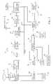
- FIG. 1is a block diagram of an electronic camera in accordance with the present invention.
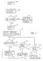
- FIG. 2is a flow diagram showing the operation of the electronic camera of FIG. 1 in accordance with a first embodiment of the present invention.
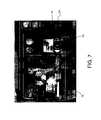
- FIG. 3is schematic of the image display on the electronic camera of FIG. 1 , displaying an exemplary captured digital image and identifying detected candidate positions of eye color defects.
- FIG. 4is a flow diagram showing the operation of the electronic camera of FIG. 1 in accordance with a second embodiment of the present invention.
- FIGS. 5( a )– 5 ( f )shows examples of indicators suitable for employment by the present invention.
- FIG. 6shows a display having two viewing areas in accordance with the present invention.
- FIGS. 7 and 8show a display having two viewing areas in accordance with the present invention.
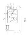
- FIG. 9generally illustrates an imaging device of a kiosk suitable for use with the present invention.
- FIG. 10is a block diagram of the kiosk in accordance with the present invention.
- FIG. 11is a flow diagram showing the operation of the kiosk of FIG. 10 in accordance with the present invention.
- Imaging devicesemploying displays and electronic sensors are well known, thus elements not specifically shown or described herein may be selected from those known in the art. Certain aspects of the embodiments to be described are provided in software. Given the system description as described in the following materials, all such software implementation is conventional and within the ordinary skill in such art.
- the present inventionis described with regard to eye color defects.
- the apparatus and method in accordance with the present inventioncan be applied to other image artifacts, including, but not limited to, scratches, tears, dust, blemishes, wrinkles, creases, hair, and specular highlights due to flash illumination.
- the present inventioncan be applied to any imaging device/system which captures and/or processes digital images, including, but not limited to, digital cameras, kiosks, photoprocessing equipment having a display, mobile or hand-held devices (such as a PDAs or cellular phones), digital camcorder, and computers.
- digital camerasincluding, but not limited to, digital cameras, kiosks, photoprocessing equipment having a display, mobile or hand-held devices (such as a PDAs or cellular phones), digital camcorder, and computers.
- mobile or hand-held devicessuch as a PDAs or cellular phones
- digital camcorderdigital camcorder
- FIG. 1there is shown a block diagram of an exemplary electronic camera 10 in accordance with the present invention, for example, the Kodak Digital Science DC210TM zoom camera sold by the Eastman Kodak Company.
- electronic camera 10includes a lens 12 which directs image light from a subject (not shown) through an aperture/shutter controller 13 upon an image sensor 14 having a discrete number of photosite elements or pixels arranged in a two-dimensional array to form individual photosites corresponding to the pixels of the image.
- Image sensor 14can be either a conventional charge coupled device (CCD) sensor, such as, for example, the Kodak KAF-1600 sensor having 1536 columns and 1024 rows of photosites, or a complementary metal oxide semiconductor (CMOS) imager.
- CCDcharge coupled device
- CMOScomplementary metal oxide semiconductor
- the photosites of image sensor 14convert the incident photons of light into electron charge packets.
- Each photositeis overlaid with a color filter array (CFA), such as the Bayer CFA described in commonly-assigned U.S. Pat. No. 3,971,065, the disclosure of which is herein incorporated by reference.
- CFAcolor filter array
- the Bayer CFAhas 50% green pixels in a checkerboard mosaic, with the remaining pixels alternating between red and blue rows.
- the photositesrespond to the appropriately colored incident light illumination to provide an analog signal corresponding to the intensity of illumination incident on the photosites.
- the analog output of each pixelis amplified and analog processed by an analog signal processor (ASP) 16 to reduce the image sensor's output amplifier noise.
- ASP 16is converted to a digital image signal by an analog-to-digital (A/D) converter 18 , such as, for example, an 8 bit AID converter which provides an 8 bit signal in the sequence of the Bayer CFA.
- A/Danalog-to-digital
- the digitized image signalis temporarily stored in a frame memory 20 , and is then processed and compressed by a digital signal processor (DSP) 22 .
- the image processingincludes white balance, color correction, tone correction, and image sharpening.
- DSP 22decimates (or resamples) the digitized image signal for each still image to produce an image having fewer pixels (i.e., lower resolution) than the original captured image, and sends the decimated image data to an image display 24 , such as a color liquid crystal display (LCD), where the user can view the image.
- the compressed image datacan also be stored in a data memory 26 or, if a memory card 28 is present in a memory card slot 30 of the electronic camera 10 , transferred through a memory card interface 32 to the memory card 28 .
- Memory card 28can be adapted to the PCMCIA card interface standard, such as described in the PC Card Standard, Release 2.0, published by the Personal Computer Memory Card International Association, Sunnyvale, Calif., September 1991. Electrical connection between memory card 28 and electronic camera 10 is maintained through a card connector (not shown) positioned in memory card slot 30 . Memory card interface 32 and the card connector provide, e.g., an interface according to the aforementioned PCMCIA card interface standard.
- the compressed image datamay also be sent to a host computer (not shown), which is connected to electronic camera 10 through a host computer interface 34 .
- a camera microprocessor 36receives user inputs 48 , such as from a shutter release (not shown), and initiates a capture sequence by triggering a flash unit 42 (if needed) and signaling a timing generator 38 .
- Timing generator 38is connected generally to the elements of electronic camera 10 , as shown in FIG. 1 , for controlling the digital conversion, compression, and storage of the image signal.
- Camera microprocessor 36also processes a signal from a photodiode 44 for determining a proper exposure, and accordingly signals an exposure driver 46 for setting the aperture and shutter speed via aperture/shutter controller 13 .
- Image sensor 14is then driven from timing generator 38 via a sensor driver 40 to produce the image signal.
- the user inputs 48are used to control the operation of electronic camera 10 in a well-known manner.
- FIG. 2shows a flow diagram of the operation of electronic camera 10 .
- an imageis captured electronically (block 102 ) by pressing the shutter button (not shown) on electronic camera 10 (block 100 ). If the image was captured using only ambient scene illumination (block 104 ), the digital image is processed by DSP 22 and stored (block 106 ). If flash unit 42 was triggered during image capture to provide for flash illumination (block 104 ), an eye color defect detection algorithm is automatically run to detect for one or more candidate positions of eye color defects in digital image (block 108 ). In accordance with the present invention, application program or software containing the eye color defect detection algorithm is stored in memory in DSP 22 .
- the eye defect detection algorithmdetermines if any candidate positions of eye color defects are detected in the digital image (block 110 ). If no candidate positions of eye color defects are detected, DSP 22 sends the image data to data memory 26 for storage (block 112 ). If one or more candidate positions of eye color defects are detected in the digital image, an eye color defect correction algorithm is automatically run to correct for the eye color defect at that candidate position (block 113 ). Accordingly, all the detected eye color defects are automatically corrected using the eye color defect correction algorithm.
- the application program or software containing the eye color defect correction algorithmis stored in memory in DSP 22 .
- Examples of eye color defect correction algorithms which can be used in accordance with the present inventionare disclosed in commonly-assigned U.S. Pat. Nos. 5,432,863, 5,748,764 and 6,134,339, the disclosures of which are herein incorporated by reference.
- the red-eye defect corrected image(i.e., the image comprising the corrected eye color defects, hereinafter referred to as the corrected image or enhanced image) is presented/displayed on LCD 24 of electronic camera 10 . It would be understood by one skilled in the art that at this point, electronic camera 10 can present all or only a portion of the digital image which contains the corrected eye color defects. In this manner, a low resolution of LCD 24 can be matched to a stored image resolution.
- all corrected positions of eye color defectsare indicated on LCD by an indicator or other such distinctive mark (block 114 ).
- an indicator or other such distinctive markfor example, a cross-hair located at or proximate to each corrected eye color defect.
- FIG. 3is a schematic of LCD 24 on electronic camera 10 displaying an exemplary corrected image wherein electronic camera 10 captured the digital image.
- Indicatorsare displayed to indicate positions of eye color defects detected and automatically corrected by the eye color defect detection algorithm.
- four positions of eye color defects50 a , 50 b , 50 c , and 50 d ) were detected and automatically corrected, and exemplary cross-hairs are used to indicate these four corrected positions in the corrected image.
- the usercan indicate acceptance of the corrected image, for example, by pressing a button 52 (which is one of user inputs 48 shown in FIG. 1 ) on electronic camera 10 .
- the usercan indicate rejection of the corrected image by pressing a button 53 (which in one of user inputs 48 shown in FIG. 1 ).
- the usercan choose which corrected position to further correct. That is, the user can manually move/navigate from one corrected position to another corrected position (blocks 116 and 122 ), and highlight that corrected position for further/additional correction.
- the usermay choose to further correct the positions 50 c and 50 d which were detected as red-eye, but were actually red Christmas tree lights.
- a button 54which is one of the user inputs 48 shown in FIG. 1 .
- “further correcting”may mean “uncorrecting” (i.e., in the present example, the user may desire to return the tree light to its original color).
- the eye color defect correction algorithmis automatically run to further/re-correct for the eye color defect at that position (blocks 118 and 120 ). For example, perhaps some level of red color remains in the eye. Alternatively, the user can select all corrected positions to be further corrected.
- the usercan indicate the level of further correction at each corrected position by, for example, use of a slider control or up/down buttons (not shown) on electronic camera 10 .
- the further correction of the eye color defectoccurs in real-time as the user changes the correction level.
- the usermay select a plurality of positions and apply a single further correction to the plurality of selected positions. Selection means can be provided for indicating acceptance or rejection of a corrected eye color defect.
- the present inventioncan include selection means for selecting at least one undetected candidate position of eye color defect, and correction means for applying the algorithm to the selected undetected candidate position, whereby the eye color defect is corrected.
- this eye color defect correction algorithmi.e., the algorithm for further correction of corrected positions
- the algorithms run at block 113 and 120can be the same or different algorithm. If the same algorithm, variables/coefficients or variations can be changed to affect a different result. For example, the variables/coefficients may be changed to affect a more liberal detection/removal of the eye color defect or to affect a more gradual removal of eye color defects.
- the usercan then highlight another corrected position on the digital image (block 122 ) to further correct.
- electronic camera 10can automatically advance to the next corrected position on the digital image and highlight that position. The user can then choose whether to further correct that position.
- the digital imageis stored in data memory 26 (block 126 ).
- the corrected digital imagecan also be transferred to the host computer or to an external printer (not shown) for printing.
- FIG. 4a flow diagram of the operation of electronic camera 10 in accordance with a second embodiment of the present invention is shown in which the captured images are stored prior to detection and correction of candidate positions of eye color defects.
- an imageis captured electronically (block 202 ) by pressing the shutter button on the electronic camera 10 (block 200 ).
- the captured imageis then processed, as described above in conjunction with FIG. 1 , and stored in data memory 26 (block 204 ).
- the usercan then review the stored image immediately after storage or at a later time and choose whether to detect and correct any candidate positions of eye color defects in the digital image (block 206 ). If the user does not choose to detect and correct any candidate positions of eye color defects in the captured digital image, the user can then choose to capture another image (block 208 ) by pressing the shutter button on electronic camera 10 .
- the user inputs 48are signaled and the eye color defect detection algorithm is run (block 210 ). If one or more candidate positions of eye color defects have been detected in the digital image (block 212 ), an eye color defect correction algorithm is automatically run to correct for the eye color defect at that candidate position (block 213 ). Accordingly, all the detected eye color defects are automatically corrected using the eye color defect correction algorithm. Thereafter, the operation of electronic camera 10 to select and further correct particular corrected positions is the same as described in conjunction with the first embodiment of the present invention as shown in FIG. 2 . Specifically, the image is displayed on LCD 24 of electronic camera 10 . In addition, all corrected positions of eye color defects on the displayed image are indicated to a user by the indicator or distinctive mark, such as, for example, a cross-hair located at or proximate to each corrected position (block 214 ).
- the indicator or distinctive marksuch as, for example, a cross-hair located at or proximate to each corrected position (block 214 ).
- the usercan then choose which corrected positions of eye color defects, if any, to correct by pressing, for example, button 52 (shown in FIG. 3 ) on electronic camera 10 , to move from one corrected position to another and highlight that position (block 216 ).
- button 52shown in FIG. 3
- the usercan select to further correct that corrected position by pressing, for example, button 54 (block 218 ).
- the eye color defect correction algorithmis automatically run to further correct for the eye color defect at that corrected position (block 220 ).
- the usercan highlight in a conventional manner another corrected position on the digital image (block 222 ) by pressing button 52 and choose whether to correct that corrected position.
- the electronic camera 10automatically advances to the next corrected position on the digital image and highlights that position. The user can then choose whether to further correct that position. When all corrected positions have been highlighted and any selected positions have been further corrected, or when a period of time has elapsed without user input (block 224 ), the corrected digital image is restored in data memory 26 (block 226 ).
- Computer programs or software for providing the eye color defect detection and correction algorithms in accordance with the present inventionare stored in DSP 22 . These computer programs or software, as well as other operating functions, can be stored on a computer readable medium which can be directly input into DSP 22 .
- the computer readable storage mediummay comprise, for example, magnetic storage media such as a magnetic disc (e.g. a floppy disc) or magnetic tape; optical storage media such as an optical disc, optical tape, or a machine readable bar code; solid state electronic storage devices such as random access memory (RAM) or read only memory (ROM); or any other physical device or medium employed to store a computer program.
- electronic/digital camera 10for capturing a digital image and for detecting and correcting eye color defects of a subject in the digital image, comprising: (a) image sensor 14 for capturing and digitizing an image to produce the digital image; (b) processor 22 for detecting one or more candidate positions of eye color defects in the digital image; (c) automatic correction means for applying an eye color defect algorithm to the digital image at the detected candidate positions to automatically correct for the eye color defect; and (d) presentation means including an electronic display 24 for presenting at least a portion of the digital image comprising at least one of the one or more corrected eye color defects.
- Electronic camera 10can further include selection means for selecting at least one corrected eye color defect for further correction; and correction means for applying an eye color defect algorithm to the selected corrected eye color defect to further correct the eye color defect.
- the pixel data corresponding to the further corrected eye color defectcan then be sampled to produce a subsampled image displayable on the display.
- an indicator or other distinctive markcan be employed to indicate the eye color defect on the digital image which was corrected. That is, an indicator can be employed to indicate the one or more corrected eye color defects in the digital image.
- the indicatorcan be a predetermined shape such as a cross hair (as shown in FIG. 3 ), an icon or symbol, such as a star, circle, diamond, triangle, or square, or comprised of one or more shapes and/or symbols. Still further, the indicator can be a shadow box or shaded relative to the image. Alternatively, the image can be shaded relative to the indicator.
- the indicatorcan optionally include a number or alphabetic character so as to distinguish/number the corrected eye color defects.
- FIGS. 5( a ) through 5 ( c )provide examples of an indicator 70 .
- Indicator 70 shown in FIG. 5( a )is configured as an eye-dropper with a drop comprising a number.
- Indicator 70 shown in FIG. 5( b )is configured similar to the eye-dropper of FIG. 5( a ), though disposed on a background shape. Such a background shape may be desired for indicator 70 to be distinguishable (whether in color, shape, or size) from the object(s) of the digital image.
- Indicator 70can be located proximate the position of the corrected eye color defect or disposed on/over the corrected eye color defect.
- FIG. 5( a )shows indicator 70 located proximate the eye
- FIG. 5( c )shows indicator 70 disposed overlapping the eye.
- a single indicator 70can indicate a single corrected eye color defect, as shown in FIGS. 5( a ) through 5 ( c ).
- a single indicator 70can indicate one or more corrected eye color defects, as shown in FIGS. 5( d ) and 5 ( e ) wherein one indicator is representative of two eyes of a subject.
- indicator 70references a pair of eye color defects.
- a single indicator 70can indicate a group of eye color defects.
- Indicator 70can comprise a predetermined color to indicate an amount/level of change of the correction. That is, the color of indicator 70 can be representative of the severity of the eye color defect which was corrected. For example, the colors red, yellow, and green can be employed, with the color red representing that the defect of the image (i.e., the eye color defect) has undergone an extreme change from the source image, the color yellow representing that the defect of the image has undergone a medium change, and the color green representing that the defect of the image has undergone a slight change.
- Indicator 70can comprise a predetermined color to indicate a level of confidence of correction. That is, the color indicator 70 can be representative of the level of confidence that the eye color defect has been correctly detected and/or corrected.
- the colors red, yellow, and greencan be employed, with the color red representing a low level of confidence, the color yellow representing a medium level of confidence, and the color green representing a high level of confidence.
- indicator 70can comprise a predetermined size to indicate a level of confidence of correction. That is, the size of the indicator can be representative of the level of confidence that the eye color defect has been correctly corrected. For example, as shown in FIG. 5( f ), a first (small) indicator can represent a low level of confidence, while a second (larger) indicator can represent a high level of confidence.
- Indicatorcan comprise a predetermined color to differentiate the indicator from a background portion of the digital image where the at least one indicator is located. That is, it is desirable that indicator 70 be distinguishable from the subject of the digital image so that the user can readily identify/select indicator 70 .
- an uncommon colorcould be employed, such as a lime green or bright orange.
- a blue indicatorwould be employed if the content of the digital image (where indicator 70 would be placed) is red, or a green indicator if the content of the digital image (where indicator 70 would be placed) is yellow.
- Indicator 70can comprise a predetermined size relative to a size of the detected eye color defect. That is, the size of the indicator can be representative of the size of the eye color defect which has been corrected. For example, if the eye color defect comprises a large portion of the image, then indicator 70 can be of a larger size. Conversely, if the eye color defect comprises a small portion of the image, then indicator 70 can be of a smaller size.
- Indicator 70can comprise a predetermined size relative to a size of the digital image. That is, the area of indicator 70 would be smaller than the digital image, but not so small as to not be distinguishable/recognizable by a user, but not so large as to obscure the content of the digital image.
- Indicator 70can comprise a predetermined size relative to a location of at least a second indicator. As such, it is preferred that adjacent indicators do not overlap or overlay so that each indicator is readily distinguishable.
- Indicator 70can comprise a predetermined size relative to a number of indicators. That is, it is preferred that one indicator does not overlap or obscure another indicator. Accordingly, if more than one indicator is employed, the indicators would be arranged to not overlap. As such, the location of indicator 70 would vary based on scene content.
- textual informationcan be provided to provide additional information regarding the eye color defect.
- a “pop-up” text boxcan appear on the display when indicator 70 is selected (such as with a touch on a touchscreen, cursor, crosshairs, or other selection member).
- the textual informationcan provide specific details regarding the eye color defect, details such as the number of the eye color defect (if the number was not already displayed, i.e., number 1 of 6 eye color defects), a numerical value representative of the level of confidence of correction, a description or numerical value representative of the severity of the color defect, or a numerical value or description indicating the amount of correction required to correct the eye color defect.
- the pop-up boxcan be one level or multiple levels, that is, multiple pop-up boxes can be employed.
- indicator 70can comprise a shadow box or other image distortion to the digital image proximate the corrected eye color defect so as to provide a visual indication to the user of the location of the corrected eye color defect.
- Audiocan be employed to provide a user with instructions.
- indicator 70can be an audio indicator as well as (or rather than) a visual indicator.
- the usercan select a portion of the digital image, and a loud sound/signal can be emitted.
- Such an audio indicatorcan be of differing tones, levels, length, and/or pitch dependent on level of confidence of correction, the amount of correction, and so forth.
- Such an audio indicatormay be desired for users who are visually impaired or having some color blindness.
- LCD 24may comprise a first viewing area 72 for viewing the digital image, and a second viewing area 74 proximate first viewing area 72 for viewing an enlargement of a portion of the digital image.
- the usercan, using a selection means 76 , navigate through the corrected eye color defects for viewing, in second viewing area 74 , the corrected eye color defects and/or determining whether to further correct the corrected eye color defects. Pressing selection means 76 would automatically position the selected corrected position(s) within second viewing area 74 for the user's consideration and perusal. The enlarged view of the selected corrected position will allow the user to determine if the selected corrected position is acceptable or requires further modification.
- Indicators 70may or may not be viewed in second viewing area 74 .
- FIGS. 7 and 8illustrate further arrangements of first and second viewing areas 72 , 74 for viewing and correcting eye color defects in accordance with the present invention.
- selection means 76provides a means for selecting a particular position of an eye color defect.
- correction means 78provides a means for selecting/indicating/modifying a level of correction for a selected particular eye color defect.
- visual indicatorscan be used to indicate/mark a reviewed corrected eye color defect or to indicate/mark a further corrected eye color defect. That is, if once a corrected position has been reviewed in second viewing area 74 , a visual indicator, such as a rectangle, triangle, circle, color change, shadow box, text, or the like, can be positioned on the image about the reviewed corrected position so as to provide an indicator to the user of such review. Such review can include applying further correction, not applying further correction, or rejecting the correction. (These visual indicators can be in addition indicator 70 .
- indicator 70can change physical characteristics to provide a distinction from a previously displayed indicator so as to recognize that a review has occurred.) This feature can be desirable if a large number of corrected positions are present in the image.
- a visual indicatorcan be noted on the image to indicate that the corrected position has been further corrected.
- a triangular shaped indicatormay indicate that the position was viewed while a rectangular shaped indicator may indicate that the position was further corrected.
- the visual indicatorcan also be a color change.
- a bright green color indicatormay indicate which position(s) was viewed while a bright orange color indicator may indicate which position(s) was further corrected.
- Audio indicatorscan also be employed. For example, a low tone sound indicator may indicate that the position was viewed while a high tone sound indicator may indicate that the position was further corrected.
- FIG. 10shows a block diagram of kiosk 60 in accordance with the present invention.
- kiosk 60includes a color display 62 for presenting information to a user and displaying the user-supplied visual image.
- Color display 62can be a touchscreen display, whereby a user can provide information and data to kiosk 60 , or a keyboard 63 may be used to provide information and data.
- a scanner 64may be provided for receiving a user-supplied visual image and converting the visual image into digital form.
- an input port 65may be provided for receiving the user-supplied visual image in digital form, such as from a removable media 67 (e.g., memory card, floppy disk, compact disc, or PictureCD) readable by means of a removable media reader 68 .
- Kiosk 60can include a delivery section 66 for controlling the delivery of a medium. Delivery section 66 is illustrated in FIG. 9 as an opening in kiosk 60 . Kiosk 60 can also include a printer 61 for generating a hardcopy output of the user's image. Kiosk 60 can communicate with other systems by means of a communication network (not shown).
- kiosk 60may communicate with a home computer system, an Internet Service Provider (ISP), or service provider providing imaging products or having printers, for example, a wholesale photofinishing lab.
- ISPInternet Service Provider
- service providerproviding imaging products or having printers, for example, a wholesale photofinishing lab.
- Such a communication networkallows a consumer/user to upload and/or download an image.
- Kiosk 60includes accessing means, such as scanner 64 , input port 65 or a communication network, for accessing the digital image; (b) a processor 67 for detecting one or more candidate positions of eye color defects in the digital image; (c) automatic correction means for applying an eye color defect algorithm to the digital image at the detected candidate positions to automatically correct for the eye color defect; and (d) display 62 for presenting the digital image comprising the one or more corrected eye color defects and indicating the one or more corrected eye color defects.
- kiosk 60includes means for selecting at least one corrected eye color defect and further correcting the corrected eye color defect.
- FIG. 11shows a flow diagram of the operation of kiosk 60 , whose operation is similar to that of camera 10 shown in FIGS. 2 and 4 .
- an imageis accessed (block 300 ) by reading a digital file from removable media 67 or scanning a image using scanner 64 .
- An eye color defect detection algorithmis automatically run to detect for one or more candidate positions of eye color defects in digital image (block 108 ). Once the eye defect detection algorithm has run, it is determined if any candidate positions of eye color defects are detected in the digital image (block 110 ). If no candidate positions of eye color defects are detected, kiosk 60 waits for the next image to be accessed (block 112 ) or other instruction to kiosk 60 . If one or more candidate positions of eye color defects are detected in the digital image, an eye color defect correction algorithm is automatically run to correct for the eye color defect at that candidate position (block 113 ). Accordingly, all the detected eye color defects are automatically corrected using the eye color defect correction algorithm.
- the red-eye defect corrected image(i.e., the image comprising the corrected eye color defects, hereinafter referred to as the corrected image or enhanced image) is presented/displayed on display 62 . It would be understood by one skilled in the art that at this point, display 62 can present only a portion of the digital image which contains the corrected eye color defects. In addition, all corrected positions of eye color defects are indicated on display 62 by indicator 70 or other such distinctive mark (block 114 ).
- the usercan indicate acceptance or rejection of the corrected image.
- the usercan manually move from one corrected position to another corrected position (blocks 116 and 122 ), and highlight that corrected position for further/additional correction.
- the eye color defect correction algorithmis automatically run to further/re-correct for the eye color defect at that position (blocks 118 and 120 ).
- the usercan select all corrected positions to be further corrected.
- the usercan indicate the level of further correction at each corrected position by, for example, use of a slider control or up/down buttons (not shown), and/or select a plurality of positions and apply a single further correction to the plurality of selected positions.
- the usercan then highlight another corrected position on the digital image (block 122 ) to further correct.
- kiosk 60can automatically advance to the next corrected position on the digital image and highlight that position. The user can then choose whether to further correct that position.
- the digital imagecan be stored (block 126 ), transmitted, or printed using printer 61 .
- the digital imageFor each digital image in which one or more candidate positions of eye color defects are detected, the digital image is displayed on the LCD 24 of camera 10 (or display 62 of kiosk 60 ) and the detected candidate positions are indicated to the user on the displayed image so that the user can then selected those candidate positions to be corrected, as previously described in conjunction with FIG. 2 .
- the eye color defect correction algorithmis then run to correct the selected candidate positions.
- the corrected digital imagecan then be stored in a manner previously described.
- Metadatacan be attached to or associated with the digital file of the image to store information or data regarding the algorithm applied to the digital image, for example, how many times a particular algorithm has been applied to the particular image and/or, the coefficients of the algorithm applied.
- the metadatacan be used when the digital image is further accessed, for example, the algorithm may be configured to employ different coefficients than are stored in the metadata so that different algorithms are applied to the digital image each time the digital image is accessed.
- the metadatacan include pixel information/data.
- the pixel informationcan be the corrected pixel information and/or the pixel information previous to being corrected.
- the pixel informationcan include the entire digital image and/or just the pixels of the region of interest (i.e., those portions of the digital image having the detected eye color defects).
- the pixel informationcan be in a compressed (for example, JPEG) or uncompressed format. Including the pixel information in the metadata from previous edits (which can include a series of successive edits) allows the user to “undo” and/or “redo” in a sequential manner, the eye color defect corrections.
- the original JPEG compressed pixel informationis stored in the metadata for those portions of the digital image which correspond to the pixels which have been modified during the detection/correction.
- the modified MCU blocksare compressed, and then the unchanged blocks are transcoded.
- transcodingit is meant that the bits are shifted around without actually recompressing the unchanged MCU blocks.
- a usercan try the algorithm successively without permanently degrading the digital image. If the algorithm creates an undesirable effect, that effect can be reversed.
- all the correctionsare stored, so that using this method, the original digital image can be recovered by successively undoing the corrections.
Landscapes
- Engineering & Computer Science (AREA)
- Multimedia (AREA)
- Signal Processing (AREA)
- Physics & Mathematics (AREA)
- Ophthalmology & Optometry (AREA)
- Human Computer Interaction (AREA)
- General Health & Medical Sciences (AREA)
- General Physics & Mathematics (AREA)
- Health & Medical Sciences (AREA)
- Theoretical Computer Science (AREA)
- Computer Vision & Pattern Recognition (AREA)
- Studio Devices (AREA)
- Image Processing (AREA)
Abstract
Description
- 10 electronic camera
- 12 lens
- 13 aperture/shutter controller
- 14 image sensor
- 16 analog signal processor
- 18 analog-to-digital converter
- 20 frame memory
- 22 digital signal processor
- 24 image display
- 26 data memory
- 28 memory card
- 30 memory card slot
- 32 memory card interface
- 34 host computer interface
- 36 camera microprocessor
- 38 timing generator
- 40 sensor driver
- 42 flash unit
- 44 photodiode
- 46 exposure driver
- 48 user inputs
- 50a,50b,50c,50dcandidate positions of eye color defects
- 52 button
- 54 button
- 55 kiosk
- 56 printer
- 62 display
- 63 keyboard
- 64 scanner
- 65 input port
- 66 delivery section
- 67 removable media
- 68 removable media reader
- 69 computer/processor
- 70 indicator
- 72 first viewing area
- 73 second viewing area
- 76 selection means
- 78 correction means
Claims (42)
Priority Applications (1)
| Application Number | Priority Date | Filing Date | Title |
|---|---|---|---|
| US10/230,913US7035462B2 (en) | 2002-08-29 | 2002-08-29 | Apparatus and method for processing digital images having eye color defects |
Applications Claiming Priority (1)
| Application Number | Priority Date | Filing Date | Title |
|---|---|---|---|
| US10/230,913US7035462B2 (en) | 2002-08-29 | 2002-08-29 | Apparatus and method for processing digital images having eye color defects |
Publications (2)
| Publication Number | Publication Date |
|---|---|
| US20040041924A1 US20040041924A1 (en) | 2004-03-04 |
| US7035462B2true US7035462B2 (en) | 2006-04-25 |
Family
ID=31976625
Family Applications (1)
| Application Number | Title | Priority Date | Filing Date |
|---|---|---|---|
| US10/230,913Expired - Fee RelatedUS7035462B2 (en) | 2002-08-29 | 2002-08-29 | Apparatus and method for processing digital images having eye color defects |
Country Status (1)
| Country | Link |
|---|---|
| US (1) | US7035462B2 (en) |
Cited By (79)
| Publication number | Priority date | Publication date | Assignee | Title |
|---|---|---|---|---|
| US20040070598A1 (en)* | 2002-09-24 | 2004-04-15 | Fuji Photo Film Co., Ltd. | Image retouching method, apparatus, and program storage medium, image correcting method, apparatus, and program storage medium, and eye detecting and correcting method apparatus, and program storage medium |
| US20040093432A1 (en)* | 2002-11-07 | 2004-05-13 | Eastman Kodak Company | Method and system for conducting image processing from a mobile client device |
| US20040109614A1 (en)* | 2002-08-30 | 2004-06-10 | Fuji Photo Film Co., Ltd. | Red eye compensation method, image processing apparatus and method for implementing the red eye compensation method, as well as printing method and printer |
| US20040114796A1 (en)* | 2002-12-11 | 2004-06-17 | Toshihiko Kaku | Image correction apparatus and image pickup apparatus |
| US20040119861A1 (en)* | 2002-08-23 | 2004-06-24 | Stmicroelectronics S.R.L. | Method for filtering the noise of a digital image sequence |
| US20040126086A1 (en)* | 2002-09-30 | 2004-07-01 | Fuji Photo Film Co., Ltd. | Image recording apparatus |
| US20040196503A1 (en)* | 2003-04-07 | 2004-10-07 | Eastman Kodak Company | Index print having a correction indicator thereon and a method of making the index print |
| US20040223063A1 (en)* | 1997-10-09 | 2004-11-11 | Deluca Michael J. | Detecting red eye filter and apparatus using meta-data |
| US20050078191A1 (en)* | 2003-10-14 | 2005-04-14 | Hewlett-Packard Development Company Lp | System and method to allow undoing of certain digital image modifications |
| US20050105109A1 (en)* | 2003-10-02 | 2005-05-19 | Fuji Photo Film Co., Ltd. | Method of and apparatus for image processing and computer program |
| US20050140801A1 (en)* | 2003-08-05 | 2005-06-30 | Yury Prilutsky | Optimized performance and performance for red-eye filter method and apparatus |
| US20050163498A1 (en)* | 2004-01-28 | 2005-07-28 | Battles Amy E. | User interface for automatic red-eye removal in a digital image |
| US20050238227A1 (en)* | 2004-04-27 | 2005-10-27 | Canon Kabushiki Kaisha | Image processing apparatus, image processing method, program thereof, and recording medium |
| US20050254725A1 (en)* | 2004-04-23 | 2005-11-17 | Noriyuki Nishi | Image processing method and apparatus for red eye correction |
| US20060072815A1 (en)* | 2004-10-04 | 2006-04-06 | Donghui Wu | Enhanced automatic red eye removal |
| US20060082847A1 (en)* | 2004-10-14 | 2006-04-20 | Fuji Photo Film Co., Ltd. | Image correction apparatus and method of controlling same |
| US20060093237A1 (en)* | 2004-11-01 | 2006-05-04 | Dana Jacobsen | Systems and methods for correcting image perspective |
| US20060093212A1 (en)* | 2004-10-28 | 2006-05-04 | Eran Steinberg | Method and apparatus for red-eye detection in an acquired digital image |
| US20060120599A1 (en)* | 2004-10-28 | 2006-06-08 | Eran Steinberg | Method and apparatus for red-eye detection in an acquired digital image |
| US20060129950A1 (en)* | 2004-12-10 | 2006-06-15 | Bin Zhao | Red eye removal user interface for a portable device |
| US20060204055A1 (en)* | 2003-06-26 | 2006-09-14 | Eran Steinberg | Digital image processing using face detection information |
| US20060204110A1 (en)* | 2003-06-26 | 2006-09-14 | Eran Steinberg | Detecting orientation of digital images using face detection information |
| US20060204054A1 (en)* | 2003-06-26 | 2006-09-14 | Eran Steinberg | Digital image processing composition using face detection information |
| US20070116379A1 (en)* | 2005-11-18 | 2007-05-24 | Peter Corcoran | Two stage detection for photographic eye artifacts |
| US20070201052A1 (en)* | 2006-02-24 | 2007-08-30 | Holden Caine | Method and Apparatus for Selective Editing of an Automatic Digital Image Correction |
| US20080013800A1 (en)* | 2003-06-26 | 2008-01-17 | Fotonation Vision Limited | Method of Improving Orientation and Color Balance of Digital Images Using Face Detection Information |
| US7391442B1 (en)* | 2007-11-01 | 2008-06-24 | International Business Machines Corporation | Digital camera including a distortion correction system |
| US20080240555A1 (en)* | 2005-11-18 | 2008-10-02 | Florin Nanu | Two Stage Detection for Photographic Eye Artifacts |
| US20080292193A1 (en)* | 2007-05-24 | 2008-11-27 | Fotonation Vision Limited | Image Processing Method and Apparatus |
| US20080317353A1 (en)* | 2007-06-25 | 2008-12-25 | Intervideo, Digital Tech. Corp. | Method and system for searching images with figures and recording medium storing metadata of image |
| US20090027520A1 (en)* | 1997-10-09 | 2009-01-29 | Fotonation Vision Limited | Red-eye filter method and apparatus |
| US20090102949A1 (en)* | 2003-06-26 | 2009-04-23 | Fotonation Vision Limited | Perfecting the Effect of Flash within an Image Acquisition Devices using Face Detection |
| US20090244296A1 (en)* | 2008-03-26 | 2009-10-01 | Fotonation Ireland Limited | Method of making a digital camera image of a scene including the camera user |
| US7599577B2 (en) | 2005-11-18 | 2009-10-06 | Fotonation Vision Limited | Method and apparatus of correcting hybrid flash artifacts in digital images |
| US20090256947A1 (en)* | 2008-04-15 | 2009-10-15 | Sony Corporation | Method and apparatus for performing touch-based adjustments within imaging devices |
| US7616233B2 (en) | 2003-06-26 | 2009-11-10 | Fotonation Vision Limited | Perfecting of digital image capture parameters within acquisition devices using face detection |
| US7620218B2 (en) | 2006-08-11 | 2009-11-17 | Fotonation Ireland Limited | Real-time face tracking with reference images |
| US20100039520A1 (en)* | 2008-08-14 | 2010-02-18 | Fotonation Ireland Limited | In-Camera Based Method of Detecting Defect Eye with High Accuracy |
| US20100050188A1 (en)* | 2007-01-11 | 2010-02-25 | Koninklijke Philips Electronics N.V. | Method and apparatus for providing an undo/redo mechanism |
| US7684630B2 (en) | 2003-06-26 | 2010-03-23 | Fotonation Vision Limited | Digital image adjustable compression and resolution using face detection information |
| US20100272363A1 (en)* | 2007-03-05 | 2010-10-28 | Fotonation Vision Limited | Face searching and detection in a digital image acquisition device |
| US7844076B2 (en) | 2003-06-26 | 2010-11-30 | Fotonation Vision Limited | Digital image processing using face detection and skin tone information |
| US7864990B2 (en) | 2006-08-11 | 2011-01-04 | Tessera Technologies Ireland Limited | Real-time face tracking in a digital image acquisition device |
| US7916897B2 (en) | 2006-08-11 | 2011-03-29 | Tessera Technologies Ireland Limited | Face tracking for controlling imaging parameters |
| US7916190B1 (en) | 1997-10-09 | 2011-03-29 | Tessera Technologies Ireland Limited | Red-eye filter method and apparatus |
| US7953251B1 (en) | 2004-10-28 | 2011-05-31 | Tessera Technologies Ireland Limited | Method and apparatus for detection and correction of flash-induced eye defects within digital images using preview or other reference images |
| US7962629B2 (en) | 2005-06-17 | 2011-06-14 | Tessera Technologies Ireland Limited | Method for establishing a paired connection between media devices |
| US7965875B2 (en) | 2006-06-12 | 2011-06-21 | Tessera Technologies Ireland Limited | Advances in extending the AAM techniques from grayscale to color images |
| US7970182B2 (en) | 2005-11-18 | 2011-06-28 | Tessera Technologies Ireland Limited | Two stage detection for photographic eye artifacts |
| US7995804B2 (en) | 2007-03-05 | 2011-08-09 | Tessera Technologies Ireland Limited | Red eye false positive filtering using face location and orientation |
| US8000526B2 (en) | 2007-11-08 | 2011-08-16 | Tessera Technologies Ireland Limited | Detecting redeye defects in digital images |
| US8036460B2 (en) | 2004-10-28 | 2011-10-11 | DigitalOptics Corporation Europe Limited | Analyzing partial face regions for red-eye detection in acquired digital images |
| US8050465B2 (en) | 2006-08-11 | 2011-11-01 | DigitalOptics Corporation Europe Limited | Real-time face tracking in a digital image acquisition device |
| US8055067B2 (en) | 2007-01-18 | 2011-11-08 | DigitalOptics Corporation Europe Limited | Color segmentation |
| US20110310113A1 (en)* | 2005-12-19 | 2011-12-22 | Adobe Systems Incorporated | Displaying generated changes to an image file |
| US8155397B2 (en) | 2007-09-26 | 2012-04-10 | DigitalOptics Corporation Europe Limited | Face tracking in a camera processor |
| US8170294B2 (en) | 2006-11-10 | 2012-05-01 | DigitalOptics Corporation Europe Limited | Method of detecting redeye in a digital image |
| US8170350B2 (en) | 2004-08-16 | 2012-05-01 | DigitalOptics Corporation Europe Limited | Foreground/background segmentation in digital images |
| US8184900B2 (en) | 2006-02-14 | 2012-05-22 | DigitalOptics Corporation Europe Limited | Automatic detection and correction of non-red eye flash defects |
| US8213737B2 (en) | 2007-06-21 | 2012-07-03 | DigitalOptics Corporation Europe Limited | Digital image enhancement with reference images |
| US8212864B2 (en) | 2008-01-30 | 2012-07-03 | DigitalOptics Corporation Europe Limited | Methods and apparatuses for using image acquisition data to detect and correct image defects |
| US8224039B2 (en) | 2007-02-28 | 2012-07-17 | DigitalOptics Corporation Europe Limited | Separating a directional lighting variability in statistical face modelling based on texture space decomposition |
| US8330831B2 (en) | 2003-08-05 | 2012-12-11 | DigitalOptics Corporation Europe Limited | Method of gathering visual meta data using a reference image |
| US8345114B2 (en) | 2008-07-30 | 2013-01-01 | DigitalOptics Corporation Europe Limited | Automatic face and skin beautification using face detection |
| US8379917B2 (en) | 2009-10-02 | 2013-02-19 | DigitalOptics Corporation Europe Limited | Face recognition performance using additional image features |
| US8494286B2 (en) | 2008-02-05 | 2013-07-23 | DigitalOptics Corporation Europe Limited | Face detection in mid-shot digital images |
| US8498452B2 (en) | 2003-06-26 | 2013-07-30 | DigitalOptics Corporation Europe Limited | Digital image processing using face detection information |
| US8503818B2 (en) | 2007-09-25 | 2013-08-06 | DigitalOptics Corporation Europe Limited | Eye defect detection in international standards organization images |
| US8503800B2 (en) | 2007-03-05 | 2013-08-06 | DigitalOptics Corporation Europe Limited | Illumination detection using classifier chains |
| US8520093B2 (en) | 2003-08-05 | 2013-08-27 | DigitalOptics Corporation Europe Limited | Face tracker and partial face tracker for red-eye filter method and apparatus |
| US8593542B2 (en) | 2005-12-27 | 2013-11-26 | DigitalOptics Corporation Europe Limited | Foreground/background separation using reference images |
| US20140071310A1 (en)* | 2012-09-10 | 2014-03-13 | Sony Corporation | Image processing apparatus, method, and program |
| US8675991B2 (en) | 2003-06-26 | 2014-03-18 | DigitalOptics Corporation Europe Limited | Modification of post-viewing parameters for digital images using region or feature information |
| US8682097B2 (en) | 2006-02-14 | 2014-03-25 | DigitalOptics Corporation Europe Limited | Digital image enhancement with reference images |
| US8989453B2 (en) | 2003-06-26 | 2015-03-24 | Fotonation Limited | Digital image processing using face detection information |
| US9129381B2 (en) | 2003-06-26 | 2015-09-08 | Fotonation Limited | Modification of post-viewing parameters for digital images using image region or feature information |
| WO2015200247A1 (en) | 2014-06-25 | 2015-12-30 | Kodak Alaris Inc. | Adaptable eye artifact identification and correction system |
| US9412007B2 (en) | 2003-08-05 | 2016-08-09 | Fotonation Limited | Partial face detector red-eye filter method and apparatus |
| US9692964B2 (en) | 2003-06-26 | 2017-06-27 | Fotonation Limited | Modification of post-viewing parameters for digital images using image region or feature information |
Families Citing this family (44)
| Publication number | Priority date | Publication date | Assignee | Title |
|---|---|---|---|---|
| US7035462B2 (en)* | 2002-08-29 | 2006-04-25 | Eastman Kodak Company | Apparatus and method for processing digital images having eye color defects |
| JP2004206688A (en)* | 2002-12-12 | 2004-07-22 | Fuji Photo Film Co Ltd | Face recognition method, face image cutting out method, and imaging apparatus |
| US7180529B2 (en)* | 2002-12-19 | 2007-02-20 | Eastman Kodak Company | Immersive image viewing system and method |
| EP1453006A1 (en)* | 2003-02-28 | 2004-09-01 | Océ-Technologies B.V. | Converted digital colour image with improved colour distinction for colour-blinds |
| US7224850B2 (en)* | 2003-05-13 | 2007-05-29 | Microsoft Corporation | Modification of red-eye-effect in digital image |
| EP1499111B1 (en)* | 2003-07-15 | 2015-01-07 | Canon Kabushiki Kaisha | Image sensiting apparatus, image processing apparatus, and control method thereof |
| JP2005094571A (en)* | 2003-09-19 | 2005-04-07 | Fuji Photo Film Co Ltd | Camera with red-eye correcting function |
| KR100587333B1 (en)* | 2003-11-07 | 2006-06-08 | 엘지전자 주식회사 | Color correction method and device for visual display considering visual characteristics of color weak people |
| JP4262065B2 (en)* | 2003-11-28 | 2009-05-13 | キヤノン株式会社 | Imaging apparatus, control method therefor, and printer |
| KR100627048B1 (en)* | 2003-12-15 | 2006-09-25 | 삼성테크윈 주식회사 | Digital Camera Control Method |
| US20110102643A1 (en)* | 2004-02-04 | 2011-05-05 | Tessera Technologies Ireland Limited | Partial Face Detector Red-Eye Filter Method and Apparatus |
| JP2005309409A (en)* | 2004-03-25 | 2005-11-04 | Fuji Photo Film Co Ltd | Red-eye preventing device, program and recording medium with recorded program |
| JP4078334B2 (en)* | 2004-06-14 | 2008-04-23 | キヤノン株式会社 | Image processing apparatus and image processing method |
| KR100702397B1 (en)* | 2004-06-14 | 2007-04-02 | 후지필름 가부시키가이샤 | Computer-readable recording medium recording image processing system, method and image processing program |
| JP2006116831A (en)* | 2004-10-22 | 2006-05-11 | Sony Corp | Printer and method of controlling it |
| JP4448039B2 (en)* | 2005-01-26 | 2010-04-07 | キヤノン株式会社 | Imaging apparatus and control method thereof |
| US20060280375A1 (en)* | 2005-06-08 | 2006-12-14 | Dalton Dan L | Red-eye correction method and apparatus with user-adjustable threshold |
| US7792355B2 (en) | 2006-03-30 | 2010-09-07 | Canon Kabushiki Kaisha | Image processing apparatus, image processing method, and image capturing apparatus |
| US7830418B2 (en)* | 2006-04-28 | 2010-11-09 | Hewlett-Packard Development Company, L.P. | Perceptually-derived red-eye correction |
| US7889242B2 (en)* | 2006-10-26 | 2011-02-15 | Hewlett-Packard Development Company, L.P. | Blemish repair tool for digital photographs in a camera |
| JP2008245055A (en)* | 2007-03-28 | 2008-10-09 | Fujifilm Corp | Image display device, photographing device, and image display method |
| US8929614B2 (en)* | 2009-10-19 | 2015-01-06 | Hewlett-Packard Development Company, L.P. | Red eye detection aided by face detection |
| US20120013750A1 (en)* | 2010-07-16 | 2012-01-19 | Gn Netcom A/S | Sound Optimization Via Camera |
| JP5746550B2 (en)* | 2011-04-25 | 2015-07-08 | キヤノン株式会社 | Image processing apparatus and image processing method |
| US8571271B2 (en) | 2011-05-26 | 2013-10-29 | Microsoft Corporation | Dual-phase red eye correction |
| US20130329114A1 (en)* | 2012-06-08 | 2013-12-12 | Samsung Electronics Co., Ltd. | Image magnifier for pin-point control |
| EP3286915B1 (en) | 2015-04-23 | 2021-12-08 | Apple Inc. | Digital viewfinder user interface for multiple cameras |
| US10009536B2 (en) | 2016-06-12 | 2018-06-26 | Apple Inc. | Applying a simulated optical effect based on data received from multiple camera sensors |
| DK180859B1 (en) | 2017-06-04 | 2022-05-23 | Apple Inc | USER INTERFACE CAMERA EFFECTS |
| US11112964B2 (en) | 2018-02-09 | 2021-09-07 | Apple Inc. | Media capture lock affordance for graphical user interface |
| US10375313B1 (en) | 2018-05-07 | 2019-08-06 | Apple Inc. | Creative camera |
| US11722764B2 (en) | 2018-05-07 | 2023-08-08 | Apple Inc. | Creative camera |
| DK201870623A1 (en) | 2018-09-11 | 2020-04-15 | Apple Inc. | User interfaces for simulated depth effects |
| US11321857B2 (en) | 2018-09-28 | 2022-05-03 | Apple Inc. | Displaying and editing images with depth information |
| US11128792B2 (en) | 2018-09-28 | 2021-09-21 | Apple Inc. | Capturing and displaying images with multiple focal planes |
| US10645294B1 (en) | 2019-05-06 | 2020-05-05 | Apple Inc. | User interfaces for capturing and managing visual media |
| US11706521B2 (en) | 2019-05-06 | 2023-07-18 | Apple Inc. | User interfaces for capturing and managing visual media |
| US11770601B2 (en) | 2019-05-06 | 2023-09-26 | Apple Inc. | User interfaces for capturing and managing visual media |
| US11054973B1 (en) | 2020-06-01 | 2021-07-06 | Apple Inc. | User interfaces for managing media |
| US11212449B1 (en) | 2020-09-25 | 2021-12-28 | Apple Inc. | User interfaces for media capture and management |
| US11539876B2 (en) | 2021-04-30 | 2022-12-27 | Apple Inc. | User interfaces for altering visual media |
| US11778339B2 (en) | 2021-04-30 | 2023-10-03 | Apple Inc. | User interfaces for altering visual media |
| US12112024B2 (en) | 2021-06-01 | 2024-10-08 | Apple Inc. | User interfaces for managing media styles |
| US20240373121A1 (en) | 2023-05-05 | 2024-11-07 | Apple Inc. | User interfaces for controlling media capture settings |
Citations (18)
| Publication number | Priority date | Publication date | Assignee | Title |
|---|---|---|---|---|
| US3971065A (en) | 1975-03-05 | 1976-07-20 | Eastman Kodak Company | Color imaging array |
| US4531150A (en)* | 1982-11-05 | 1985-07-23 | Konishiroku Photo Industry Co., Ltd. | Image display system |
| US4831434A (en)* | 1986-08-29 | 1989-05-16 | Agfa Gevaert Aktiengesellschaft | Method of correcting color saturation in electronic image processing |
| US5130789A (en) | 1989-12-13 | 1992-07-14 | Eastman Kodak Company | Localized image recoloring using ellipsoid boundary function |
| US5432863A (en) | 1993-07-19 | 1995-07-11 | Eastman Kodak Company | Automated detection and correction of eye color defects due to flash illumination |
| US5596346A (en) | 1994-07-22 | 1997-01-21 | Eastman Kodak Company | Method and apparatus for applying a function to a localized area of a digital image using a window |
| US5892837A (en) | 1997-08-29 | 1999-04-06 | Eastman Kodak Company | Computer program product for locating objects in an image |
| US5990901A (en)* | 1997-06-27 | 1999-11-23 | Microsoft Corporation | Model based image editing and correction |
| US6016354A (en)* | 1997-10-23 | 2000-01-18 | Hewlett-Packard Company | Apparatus and a method for reducing red-eye in a digital image |
| US6134339A (en) | 1998-09-17 | 2000-10-17 | Eastman Kodak Company | Method and apparatus for determining the position of eyes and for correcting eye-defects in a captured frame |
| US6151403A (en) | 1997-08-29 | 2000-11-21 | Eastman Kodak Company | Method for automatic detection of human eyes in digital images |
| US6252976B1 (en) | 1997-08-29 | 2001-06-26 | Eastman Kodak Company | Computer program product for redeye detection |
| US6292574B1 (en) | 1997-08-29 | 2001-09-18 | Eastman Kodak Company | Computer program product for redeye detection |
| US6407777B1 (en) | 1997-10-09 | 2002-06-18 | Deluca Michael Joseph | Red-eye filter method and apparatus |
| US6631208B1 (en)* | 1998-05-29 | 2003-10-07 | Fuji Photo Film Co., Ltd. | Image processing method |
| US20040041924A1 (en)* | 2002-08-29 | 2004-03-04 | White Timothy J. | Apparatus and method for processing digital images having eye color defects |
| US6873743B2 (en)* | 2001-03-29 | 2005-03-29 | Fotonation Holdings, Llc | Method and apparatus for the automatic real-time detection and correction of red-eye defects in batches of digital images or in handheld appliances |
| US6885766B2 (en)* | 2001-01-31 | 2005-04-26 | Imaging Solutions Ag | Automatic color defect correction |
- 2002
- 2002-08-29USUS10/230,913patent/US7035462B2/ennot_activeExpired - Fee Related
Patent Citations (20)
| Publication number | Priority date | Publication date | Assignee | Title |
|---|---|---|---|---|
| US3971065A (en) | 1975-03-05 | 1976-07-20 | Eastman Kodak Company | Color imaging array |
| US4531150A (en)* | 1982-11-05 | 1985-07-23 | Konishiroku Photo Industry Co., Ltd. | Image display system |
| US4831434A (en)* | 1986-08-29 | 1989-05-16 | Agfa Gevaert Aktiengesellschaft | Method of correcting color saturation in electronic image processing |
| US5130789A (en) | 1989-12-13 | 1992-07-14 | Eastman Kodak Company | Localized image recoloring using ellipsoid boundary function |
| US5432863A (en) | 1993-07-19 | 1995-07-11 | Eastman Kodak Company | Automated detection and correction of eye color defects due to flash illumination |
| US5748764A (en) | 1993-07-19 | 1998-05-05 | Eastman Kodak Company | Automated detection and correction of eye color defects due to flash illumination |
| US5596346A (en) | 1994-07-22 | 1997-01-21 | Eastman Kodak Company | Method and apparatus for applying a function to a localized area of a digital image using a window |
| US5990901A (en)* | 1997-06-27 | 1999-11-23 | Microsoft Corporation | Model based image editing and correction |
| US6072893A (en) | 1997-08-29 | 2000-06-06 | Eastman Kodak Company | Method and system for locating objects in an image |
| US5892837A (en) | 1997-08-29 | 1999-04-06 | Eastman Kodak Company | Computer program product for locating objects in an image |
| US6151403A (en) | 1997-08-29 | 2000-11-21 | Eastman Kodak Company | Method for automatic detection of human eyes in digital images |
| US6252976B1 (en) | 1997-08-29 | 2001-06-26 | Eastman Kodak Company | Computer program product for redeye detection |
| US6292574B1 (en) | 1997-08-29 | 2001-09-18 | Eastman Kodak Company | Computer program product for redeye detection |
| US6407777B1 (en) | 1997-10-09 | 2002-06-18 | Deluca Michael Joseph | Red-eye filter method and apparatus |
| US6016354A (en)* | 1997-10-23 | 2000-01-18 | Hewlett-Packard Company | Apparatus and a method for reducing red-eye in a digital image |
| US6631208B1 (en)* | 1998-05-29 | 2003-10-07 | Fuji Photo Film Co., Ltd. | Image processing method |
| US6134339A (en) | 1998-09-17 | 2000-10-17 | Eastman Kodak Company | Method and apparatus for determining the position of eyes and for correcting eye-defects in a captured frame |
| US6885766B2 (en)* | 2001-01-31 | 2005-04-26 | Imaging Solutions Ag | Automatic color defect correction |
| US6873743B2 (en)* | 2001-03-29 | 2005-03-29 | Fotonation Holdings, Llc | Method and apparatus for the automatic real-time detection and correction of red-eye defects in batches of digital images or in handheld appliances |
| US20040041924A1 (en)* | 2002-08-29 | 2004-03-04 | White Timothy J. | Apparatus and method for processing digital images having eye color defects |
Non-Patent Citations (3)
| Title |
|---|
| Patent Application, U.S. Appl. No. 09/290,290-Entitled: Eye Color Defect Detection and Correction in a Digital Image, John R. Fredlund, et al, Filed Apr. 13, 1999. |
| Patent Application, U.S. Appl. No. 09/975,903. Entitled: Method and Apparatus for Printing and/or Displaying Digital Images, Thomas J. Murray, et al, Filed Oct. 12, 2001. |
| PC Card Standard, Release 2.0, Sep. 1991, Published by Personal Computer Memory Card International Association (PCMCIA). |
Cited By (172)
| Publication number | Priority date | Publication date | Assignee | Title |
|---|---|---|---|---|
| US7738015B2 (en) | 1997-10-09 | 2010-06-15 | Fotonation Vision Limited | Red-eye filter method and apparatus |
| US7847839B2 (en) | 1997-10-09 | 2010-12-07 | Fotonation Vision Limited | Detecting red eye filter and apparatus using meta-data |
| US20080292183A1 (en)* | 1997-10-09 | 2008-11-27 | Fotonation Ireland Limited | Detecting red eye filter and apparatus using meta-data |
| US20090027520A1 (en)* | 1997-10-09 | 2009-01-29 | Fotonation Vision Limited | Red-eye filter method and apparatus |
| US7630006B2 (en) | 1997-10-09 | 2009-12-08 | Fotonation Ireland Limited | Detecting red eye filter and apparatus using meta-data |
| US7746385B2 (en) | 1997-10-09 | 2010-06-29 | Fotonation Vision Limited | Red-eye filter method and apparatus |
| US7852384B2 (en) | 1997-10-09 | 2010-12-14 | Fotonation Vision Limited | Detecting red eye filter and apparatus using meta-data |
| US20040223063A1 (en)* | 1997-10-09 | 2004-11-11 | Deluca Michael J. | Detecting red eye filter and apparatus using meta-data |
| US8203621B2 (en) | 1997-10-09 | 2012-06-19 | DigitalOptics Corporation Europe Limited | Red-eye filter method and apparatus |
| US7916190B1 (en) | 1997-10-09 | 2011-03-29 | Tessera Technologies Ireland Limited | Red-eye filter method and apparatus |
| US7787022B2 (en) | 1997-10-09 | 2010-08-31 | Fotonation Vision Limited | Red-eye filter method and apparatus |
| US7804531B2 (en) | 1997-10-09 | 2010-09-28 | Fotonation Vision Limited | Detecting red eye filter and apparatus using meta-data |
| US8264575B1 (en) | 1997-10-09 | 2012-09-11 | DigitalOptics Corporation Europe Limited | Red eye filter method and apparatus |
| US7847840B2 (en) | 1997-10-09 | 2010-12-07 | Fotonation Vision Limited | Detecting red eye filter and apparatus using meta-data |
| US7734110B2 (en)* | 2002-08-23 | 2010-06-08 | Stmicroelectronics S.R.L | Method for filtering the noise of a digital image sequence |
| US20040119861A1 (en)* | 2002-08-23 | 2004-06-24 | Stmicroelectronics S.R.L. | Method for filtering the noise of a digital image sequence |
| US20040109614A1 (en)* | 2002-08-30 | 2004-06-10 | Fuji Photo Film Co., Ltd. | Red eye compensation method, image processing apparatus and method for implementing the red eye compensation method, as well as printing method and printer |
| US7397969B2 (en)* | 2002-08-30 | 2008-07-08 | Fujifilm Corporation | Red eye compensation method, image processing apparatus and method for implementing the red eye compensation method, as well as printing method and printer |
| US20040070598A1 (en)* | 2002-09-24 | 2004-04-15 | Fuji Photo Film Co., Ltd. | Image retouching method, apparatus, and program storage medium, image correcting method, apparatus, and program storage medium, and eye detecting and correcting method apparatus, and program storage medium |
| US7277589B2 (en)* | 2002-09-24 | 2007-10-02 | Fujifilm Corporation | Image retouching method, apparatus, and program storage medium, image correcting method, apparatus, and program storage medium, and eye detecting and correcting method apparatus, and program storage medium |
| US20040126086A1 (en)* | 2002-09-30 | 2004-07-01 | Fuji Photo Film Co., Ltd. | Image recording apparatus |
| US20040093432A1 (en)* | 2002-11-07 | 2004-05-13 | Eastman Kodak Company | Method and system for conducting image processing from a mobile client device |
| US20040114796A1 (en)* | 2002-12-11 | 2004-06-17 | Toshihiko Kaku | Image correction apparatus and image pickup apparatus |
| US20040196503A1 (en)* | 2003-04-07 | 2004-10-07 | Eastman Kodak Company | Index print having a correction indicator thereon and a method of making the index print |
| US20060204054A1 (en)* | 2003-06-26 | 2006-09-14 | Eran Steinberg | Digital image processing composition using face detection information |
| US8265399B2 (en) | 2003-06-26 | 2012-09-11 | DigitalOptics Corporation Europe Limited | Detecting orientation of digital images using face detection information |
| US7317815B2 (en)* | 2003-06-26 | 2008-01-08 | Fotonation Vision Limited | Digital image processing composition using face detection information |
| US20080013800A1 (en)* | 2003-06-26 | 2008-01-17 | Fotonation Vision Limited | Method of Improving Orientation and Color Balance of Digital Images Using Face Detection Information |
| US8005265B2 (en) | 2003-06-26 | 2011-08-23 | Tessera Technologies Ireland Limited | Digital image processing using face detection information |
| US9129381B2 (en) | 2003-06-26 | 2015-09-08 | Fotonation Limited | Modification of post-viewing parameters for digital images using image region or feature information |
| US9692964B2 (en) | 2003-06-26 | 2017-06-27 | Fotonation Limited | Modification of post-viewing parameters for digital images using image region or feature information |
| US8055090B2 (en) | 2003-06-26 | 2011-11-08 | DigitalOptics Corporation Europe Limited | Digital image processing using face detection information |
| US9053545B2 (en) | 2003-06-26 | 2015-06-09 | Fotonation Limited | Modification of viewing parameters for digital images using face detection information |
| US8989453B2 (en) | 2003-06-26 | 2015-03-24 | Fotonation Limited | Digital image processing using face detection information |
| US8126208B2 (en) | 2003-06-26 | 2012-02-28 | DigitalOptics Corporation Europe Limited | Digital image processing using face detection information |
| US7912245B2 (en) | 2003-06-26 | 2011-03-22 | Tessera Technologies Ireland Limited | Method of improving orientation and color balance of digital images using face detection information |
| US8948468B2 (en) | 2003-06-26 | 2015-02-03 | Fotonation Limited | Modification of viewing parameters for digital images using face detection information |
| US8131016B2 (en) | 2003-06-26 | 2012-03-06 | DigitalOptics Corporation Europe Limited | Digital image processing using face detection information |
| US20060204110A1 (en)* | 2003-06-26 | 2006-09-14 | Eran Steinberg | Detecting orientation of digital images using face detection information |
| US8675991B2 (en) | 2003-06-26 | 2014-03-18 | DigitalOptics Corporation Europe Limited | Modification of post-viewing parameters for digital images using region or feature information |
| US20090102949A1 (en)* | 2003-06-26 | 2009-04-23 | Fotonation Vision Limited | Perfecting the Effect of Flash within an Image Acquisition Devices using Face Detection |
| US7860274B2 (en) | 2003-06-26 | 2010-12-28 | Fotonation Vision Limited | Digital image processing using face detection information |
| US7565030B2 (en) | 2003-06-26 | 2009-07-21 | Fotonation Vision Limited | Detecting orientation of digital images using face detection information |
| US7574016B2 (en) | 2003-06-26 | 2009-08-11 | Fotonation Vision Limited | Digital image processing using face detection information |
| US7853043B2 (en) | 2003-06-26 | 2010-12-14 | Tessera Technologies Ireland Limited | Digital image processing using face detection information |
| US7848549B2 (en) | 2003-06-26 | 2010-12-07 | Fotonation Vision Limited | Digital image processing using face detection information |
| US8498452B2 (en) | 2003-06-26 | 2013-07-30 | DigitalOptics Corporation Europe Limited | Digital image processing using face detection information |
| US7844076B2 (en) | 2003-06-26 | 2010-11-30 | Fotonation Vision Limited | Digital image processing using face detection and skin tone information |
| US7616233B2 (en) | 2003-06-26 | 2009-11-10 | Fotonation Vision Limited | Perfecting of digital image capture parameters within acquisition devices using face detection |
| US8326066B2 (en) | 2003-06-26 | 2012-12-04 | DigitalOptics Corporation Europe Limited | Digital image adjustable compression and resolution using face detection information |
| US7630527B2 (en)* | 2003-06-26 | 2009-12-08 | Fotonation Ireland Limited | Method of improving orientation and color balance of digital images using face detection information |
| US20060204055A1 (en)* | 2003-06-26 | 2006-09-14 | Eran Steinberg | Digital image processing using face detection information |
| US7634109B2 (en) | 2003-06-26 | 2009-12-15 | Fotonation Ireland Limited | Digital image processing using face detection information |
| US7844135B2 (en) | 2003-06-26 | 2010-11-30 | Tessera Technologies Ireland Limited | Detecting orientation of digital images using face detection information |
| US8224108B2 (en) | 2003-06-26 | 2012-07-17 | DigitalOptics Corporation Europe Limited | Digital image processing using face detection information |
| US7809162B2 (en) | 2003-06-26 | 2010-10-05 | Fotonation Vision Limited | Digital image processing using face detection information |
| US7684630B2 (en) | 2003-06-26 | 2010-03-23 | Fotonation Vision Limited | Digital image adjustable compression and resolution using face detection information |
| US20100165150A1 (en)* | 2003-06-26 | 2010-07-01 | Fotonation Vision Limited | Detecting orientation of digital images using face detection information |
| US7693311B2 (en) | 2003-06-26 | 2010-04-06 | Fotonation Vision Limited | Perfecting the effect of flash within an image acquisition devices using face detection |
| US7702136B2 (en) | 2003-06-26 | 2010-04-20 | Fotonation Vision Limited | Perfecting the effect of flash within an image acquisition devices using face detection |
| US8330831B2 (en) | 2003-08-05 | 2012-12-11 | DigitalOptics Corporation Europe Limited | Method of gathering visual meta data using a reference image |
| US20080043121A1 (en)* | 2003-08-05 | 2008-02-21 | Fotonation Vision Limited | Optimized Performance and Performance for Red-Eye Filter Method and Apparatus |
| US9412007B2 (en) | 2003-08-05 | 2016-08-09 | Fotonation Limited | Partial face detector red-eye filter method and apparatus |
| US8520093B2 (en) | 2003-08-05 | 2013-08-27 | DigitalOptics Corporation Europe Limited | Face tracker and partial face tracker for red-eye filter method and apparatus |
| US20050140801A1 (en)* | 2003-08-05 | 2005-06-30 | Yury Prilutsky | Optimized performance and performance for red-eye filter method and apparatus |
| US20050105109A1 (en)* | 2003-10-02 | 2005-05-19 | Fuji Photo Film Co., Ltd. | Method of and apparatus for image processing and computer program |
| US20050078191A1 (en)* | 2003-10-14 | 2005-04-14 | Hewlett-Packard Development Company Lp | System and method to allow undoing of certain digital image modifications |
| US20050163498A1 (en)* | 2004-01-28 | 2005-07-28 | Battles Amy E. | User interface for automatic red-eye removal in a digital image |
| US20050254725A1 (en)* | 2004-04-23 | 2005-11-17 | Noriyuki Nishi | Image processing method and apparatus for red eye correction |
| US7460707B2 (en)* | 2004-04-23 | 2008-12-02 | Noritsu Koki Co., Ltd. | Image processing method and apparatus for red eye correction |
| US7809186B2 (en)* | 2004-04-27 | 2010-10-05 | Canon Kabushiki Kaisha | Image processing apparatus, image processing method, program thereof, and recording medium |
| US20050238227A1 (en)* | 2004-04-27 | 2005-10-27 | Canon Kabushiki Kaisha | Image processing apparatus, image processing method, program thereof, and recording medium |
| US8170350B2 (en) | 2004-08-16 | 2012-05-01 | DigitalOptics Corporation Europe Limited | Foreground/background segmentation in digital images |
| US20060072815A1 (en)* | 2004-10-04 | 2006-04-06 | Donghui Wu | Enhanced automatic red eye removal |
| US7403654B2 (en)* | 2004-10-04 | 2008-07-22 | Arcsoft, Inc. | Enhanced automatic red eye removal |
| US7646415B2 (en)* | 2004-10-14 | 2010-01-12 | Fujifilm Corporation | Image correction apparatus correcting and displaying corrected area and method of controlling same |
| US20060082847A1 (en)* | 2004-10-14 | 2006-04-20 | Fuji Photo Film Co., Ltd. | Image correction apparatus and method of controlling same |
| US8265388B2 (en) | 2004-10-28 | 2012-09-11 | DigitalOptics Corporation Europe Limited | Analyzing partial face regions for red-eye detection in acquired digital images |
| US8036460B2 (en) | 2004-10-28 | 2011-10-11 | DigitalOptics Corporation Europe Limited | Analyzing partial face regions for red-eye detection in acquired digital images |
| US7587085B2 (en)* | 2004-10-28 | 2009-09-08 | Fotonation Vision Limited | Method and apparatus for red-eye detection in an acquired digital image |
| US8135184B2 (en) | 2004-10-28 | 2012-03-13 | DigitalOptics Corporation Europe Limited | Method and apparatus for detection and correction of multiple image defects within digital images using preview or other reference images |
| US7536036B2 (en) | 2004-10-28 | 2009-05-19 | Fotonation Vision Limited | Method and apparatus for red-eye detection in an acquired digital image |
| US8320641B2 (en) | 2004-10-28 | 2012-11-27 | DigitalOptics Corporation Europe Limited | Method and apparatus for red-eye detection using preview or other reference images |
| US20060120599A1 (en)* | 2004-10-28 | 2006-06-08 | Eran Steinberg | Method and apparatus for red-eye detection in an acquired digital image |
| US20060093212A1 (en)* | 2004-10-28 | 2006-05-04 | Eran Steinberg | Method and apparatus for red-eye detection in an acquired digital image |
| US7953251B1 (en) | 2004-10-28 | 2011-05-31 | Tessera Technologies Ireland Limited | Method and apparatus for detection and correction of flash-induced eye defects within digital images using preview or other reference images |
| US7990412B2 (en)* | 2004-11-01 | 2011-08-02 | Hewlett-Packard Development Company, L.P. | Systems and methods for correcting image perspective |
| US20060093237A1 (en)* | 2004-11-01 | 2006-05-04 | Dana Jacobsen | Systems and methods for correcting image perspective |
| US7483068B2 (en)* | 2004-12-10 | 2009-01-27 | Arcsoft, Inc. | Red eye removal user interface for a portable device |
| US20060129950A1 (en)* | 2004-12-10 | 2006-06-15 | Bin Zhao | Red eye removal user interface for a portable device |
| US7962629B2 (en) | 2005-06-17 | 2011-06-14 | Tessera Technologies Ireland Limited | Method for establishing a paired connection between media devices |
| US7920723B2 (en) | 2005-11-18 | 2011-04-05 | Tessera Technologies Ireland Limited | Two stage detection for photographic eye artifacts |
| US8175342B2 (en) | 2005-11-18 | 2012-05-08 | DigitalOptics Corporation Europe Limited | Two stage detection for photographic eye artifacts |
| US7970182B2 (en) | 2005-11-18 | 2011-06-28 | Tessera Technologies Ireland Limited | Two stage detection for photographic eye artifacts |
| US7970183B2 (en) | 2005-11-18 | 2011-06-28 | Tessera Technologies Ireland Limited | Two stage detection for photographic eye artifacts |
| US20070116379A1 (en)* | 2005-11-18 | 2007-05-24 | Peter Corcoran | Two stage detection for photographic eye artifacts |
| US20080240555A1 (en)* | 2005-11-18 | 2008-10-02 | Florin Nanu | Two Stage Detection for Photographic Eye Artifacts |
| US8131021B2 (en) | 2005-11-18 | 2012-03-06 | DigitalOptics Corporation Europe Limited | Two stage detection for photographic eye artifacts |
| US20110228134A1 (en)* | 2005-11-18 | 2011-09-22 | Tessera Technologies Ireland Limited | Two Stage Detection For Photographic Eye Artifacts |
| US7869628B2 (en) | 2005-11-18 | 2011-01-11 | Tessera Technologies Ireland Limited | Two stage detection for photographic eye artifacts |
| US8126218B2 (en) | 2005-11-18 | 2012-02-28 | DigitalOptics Corporation Europe Limited | Two stage detection for photographic eye artifacts |
| US7953252B2 (en)* | 2005-11-18 | 2011-05-31 | Tessera Technologies Ireland Limited | Two stage detection for photographic eye artifacts |
| US7599577B2 (en) | 2005-11-18 | 2009-10-06 | Fotonation Vision Limited | Method and apparatus of correcting hybrid flash artifacts in digital images |
| US7689009B2 (en) | 2005-11-18 | 2010-03-30 | Fotonation Vision Ltd. | Two stage detection for photographic eye artifacts |
| US7970184B2 (en) | 2005-11-18 | 2011-06-28 | Tessera Technologies Ireland Limited | Two stage detection for photographic eye artifacts |
| US7865036B2 (en) | 2005-11-18 | 2011-01-04 | Tessera Technologies Ireland Limited | Method and apparatus of correcting hybrid flash artifacts in digital images |
| US8180115B2 (en) | 2005-11-18 | 2012-05-15 | DigitalOptics Corporation Europe Limited | Two stage detection for photographic eye artifacts |
| US8160308B2 (en) | 2005-11-18 | 2012-04-17 | DigitalOptics Corporation Europe Limited | Two stage detection for photographic eye artifacts |
| US8126217B2 (en) | 2005-11-18 | 2012-02-28 | DigitalOptics Corporation Europe Limited | Two stage detection for photographic eye artifacts |
| US20110310113A1 (en)* | 2005-12-19 | 2011-12-22 | Adobe Systems Incorporated | Displaying generated changes to an image file |
| US8564615B2 (en)* | 2005-12-19 | 2013-10-22 | Adobe Systems Incorporated | Displaying generated changes to an image file |
| US8593542B2 (en) | 2005-12-27 | 2013-11-26 | DigitalOptics Corporation Europe Limited | Foreground/background separation using reference images |
| US8184900B2 (en) | 2006-02-14 | 2012-05-22 | DigitalOptics Corporation Europe Limited | Automatic detection and correction of non-red eye flash defects |
| US8682097B2 (en) | 2006-02-14 | 2014-03-25 | DigitalOptics Corporation Europe Limited | Digital image enhancement with reference images |
| US7777912B2 (en)* | 2006-02-24 | 2010-08-17 | Fujifilm North America Corporation | Method and apparatus for selective editing of an automatic digital image correction |
| US20070201052A1 (en)* | 2006-02-24 | 2007-08-30 | Holden Caine | Method and Apparatus for Selective Editing of an Automatic Digital Image Correction |
| US7965875B2 (en) | 2006-06-12 | 2011-06-21 | Tessera Technologies Ireland Limited | Advances in extending the AAM techniques from grayscale to color images |
| US7864990B2 (en) | 2006-08-11 | 2011-01-04 | Tessera Technologies Ireland Limited | Real-time face tracking in a digital image acquisition device |
| US7916897B2 (en) | 2006-08-11 | 2011-03-29 | Tessera Technologies Ireland Limited | Face tracking for controlling imaging parameters |
| US8509496B2 (en) | 2006-08-11 | 2013-08-13 | DigitalOptics Corporation Europe Limited | Real-time face tracking with reference images |
| US8055029B2 (en) | 2006-08-11 | 2011-11-08 | DigitalOptics Corporation Europe Limited | Real-time face tracking in a digital image acquisition device |
| US8385610B2 (en) | 2006-08-11 | 2013-02-26 | DigitalOptics Corporation Europe Limited | Face tracking for controlling imaging parameters |
| US7620218B2 (en) | 2006-08-11 | 2009-11-17 | Fotonation Ireland Limited | Real-time face tracking with reference images |
| US8050465B2 (en) | 2006-08-11 | 2011-11-01 | DigitalOptics Corporation Europe Limited | Real-time face tracking in a digital image acquisition device |
| US8170294B2 (en) | 2006-11-10 | 2012-05-01 | DigitalOptics Corporation Europe Limited | Method of detecting redeye in a digital image |
| US8793577B2 (en)* | 2007-01-11 | 2014-07-29 | Koninklijke Philips N.V. | Method and apparatus for providing an undo/redo mechanism |
| US20100050188A1 (en)* | 2007-01-11 | 2010-02-25 | Koninklijke Philips Electronics N.V. | Method and apparatus for providing an undo/redo mechanism |
| US8055067B2 (en) | 2007-01-18 | 2011-11-08 | DigitalOptics Corporation Europe Limited | Color segmentation |
| US8224039B2 (en) | 2007-02-28 | 2012-07-17 | DigitalOptics Corporation Europe Limited | Separating a directional lighting variability in statistical face modelling based on texture space decomposition |
| US8509561B2 (en) | 2007-02-28 | 2013-08-13 | DigitalOptics Corporation Europe Limited | Separating directional lighting variability in statistical face modelling based on texture space decomposition |
| US8649604B2 (en) | 2007-03-05 | 2014-02-11 | DigitalOptics Corporation Europe Limited | Face searching and detection in a digital image acquisition device |
| US20100272363A1 (en)* | 2007-03-05 | 2010-10-28 | Fotonation Vision Limited | Face searching and detection in a digital image acquisition device |
| US9224034B2 (en) | 2007-03-05 | 2015-12-29 | Fotonation Limited | Face searching and detection in a digital image acquisition device |
| US8503800B2 (en) | 2007-03-05 | 2013-08-06 | DigitalOptics Corporation Europe Limited | Illumination detection using classifier chains |
| US8923564B2 (en) | 2007-03-05 | 2014-12-30 | DigitalOptics Corporation Europe Limited | Face searching and detection in a digital image acquisition device |
| US7995804B2 (en) | 2007-03-05 | 2011-08-09 | Tessera Technologies Ireland Limited | Red eye false positive filtering using face location and orientation |
| US8233674B2 (en) | 2007-03-05 | 2012-07-31 | DigitalOptics Corporation Europe Limited | Red eye false positive filtering using face location and orientation |
| US7916971B2 (en) | 2007-05-24 | 2011-03-29 | Tessera Technologies Ireland Limited | Image processing method and apparatus |
| US20110234847A1 (en)* | 2007-05-24 | 2011-09-29 | Tessera Technologies Ireland Limited | Image Processing Method and Apparatus |
| US20080292193A1 (en)* | 2007-05-24 | 2008-11-27 | Fotonation Vision Limited | Image Processing Method and Apparatus |
| US20110235912A1 (en)* | 2007-05-24 | 2011-09-29 | Tessera Technologies Ireland Limited | Image Processing Method and Apparatus |
| US8515138B2 (en) | 2007-05-24 | 2013-08-20 | DigitalOptics Corporation Europe Limited | Image processing method and apparatus |
| US8494232B2 (en) | 2007-05-24 | 2013-07-23 | DigitalOptics Corporation Europe Limited | Image processing method and apparatus |
| US8213737B2 (en) | 2007-06-21 | 2012-07-03 | DigitalOptics Corporation Europe Limited | Digital image enhancement with reference images |
| US10733472B2 (en) | 2007-06-21 | 2020-08-04 | Fotonation Limited | Image capture device with contemporaneous image correction mechanism |
| US8896725B2 (en) | 2007-06-21 | 2014-11-25 | Fotonation Limited | Image capture device with contemporaneous reference image capture mechanism |
| US9767539B2 (en) | 2007-06-21 | 2017-09-19 | Fotonation Limited | Image capture device with contemporaneous image correction mechanism |
| US8170343B2 (en)* | 2007-06-25 | 2012-05-01 | Corel Corporation | Method and system for searching images with figures and recording medium storing metadata of image |
| US20080317353A1 (en)* | 2007-06-25 | 2008-12-25 | Intervideo, Digital Tech. Corp. | Method and system for searching images with figures and recording medium storing metadata of image |
| US8503818B2 (en) | 2007-09-25 | 2013-08-06 | DigitalOptics Corporation Europe Limited | Eye defect detection in international standards organization images |
| US8155397B2 (en) | 2007-09-26 | 2012-04-10 | DigitalOptics Corporation Europe Limited | Face tracking in a camera processor |
| US7515178B1 (en) | 2007-11-01 | 2009-04-07 | International Business Machines Corporation | Method of correcting distortions in digital images captured by a digital camera system |
| US7391442B1 (en)* | 2007-11-01 | 2008-06-24 | International Business Machines Corporation | Digital camera including a distortion correction system |
| US8036458B2 (en) | 2007-11-08 | 2011-10-11 | DigitalOptics Corporation Europe Limited | Detecting redeye defects in digital images |
| US8000526B2 (en) | 2007-11-08 | 2011-08-16 | Tessera Technologies Ireland Limited | Detecting redeye defects in digital images |
| US8212864B2 (en) | 2008-01-30 | 2012-07-03 | DigitalOptics Corporation Europe Limited | Methods and apparatuses for using image acquisition data to detect and correct image defects |
| US8494286B2 (en) | 2008-02-05 | 2013-07-23 | DigitalOptics Corporation Europe Limited | Face detection in mid-shot digital images |
| US8243182B2 (en) | 2008-03-26 | 2012-08-14 | DigitalOptics Corporation Europe Limited | Method of making a digital camera image of a scene including the camera user |
| US20090244296A1 (en)* | 2008-03-26 | 2009-10-01 | Fotonation Ireland Limited | Method of making a digital camera image of a scene including the camera user |
| US7855737B2 (en) | 2008-03-26 | 2010-12-21 | Fotonation Ireland Limited | Method of making a digital camera image of a scene including the camera user |
| US8259208B2 (en)* | 2008-04-15 | 2012-09-04 | Sony Corporation | Method and apparatus for performing touch-based adjustments within imaging devices |
| US20090256947A1 (en)* | 2008-04-15 | 2009-10-15 | Sony Corporation | Method and apparatus for performing touch-based adjustments within imaging devices |
| US9007480B2 (en) | 2008-07-30 | 2015-04-14 | Fotonation Limited | Automatic face and skin beautification using face detection |
| US8384793B2 (en) | 2008-07-30 | 2013-02-26 | DigitalOptics Corporation Europe Limited | Automatic face and skin beautification using face detection |
| US8345114B2 (en) | 2008-07-30 | 2013-01-01 | DigitalOptics Corporation Europe Limited | Automatic face and skin beautification using face detection |
| US20100039520A1 (en)* | 2008-08-14 | 2010-02-18 | Fotonation Ireland Limited | In-Camera Based Method of Detecting Defect Eye with High Accuracy |
| US8081254B2 (en) | 2008-08-14 | 2011-12-20 | DigitalOptics Corporation Europe Limited | In-camera based method of detecting defect eye with high accuracy |
| US8379917B2 (en) | 2009-10-02 | 2013-02-19 | DigitalOptics Corporation Europe Limited | Face recognition performance using additional image features |
| US10032068B2 (en) | 2009-10-02 | 2018-07-24 | Fotonation Limited | Method of making a digital camera image of a first scene with a superimposed second scene |
| US20140071310A1 (en)* | 2012-09-10 | 2014-03-13 | Sony Corporation | Image processing apparatus, method, and program |
| WO2015200247A1 (en) | 2014-06-25 | 2015-12-30 | Kodak Alaris Inc. | Adaptable eye artifact identification and correction system |
| US9824271B2 (en) | 2014-06-25 | 2017-11-21 | Kodak Alaris Inc. | Adaptable eye artifact identification and correction system |
Also Published As
| Publication number | Publication date |
|---|---|
| US20040041924A1 (en) | 2004-03-04 |
Similar Documents
| Publication | Publication Date | Title |
|---|---|---|
| US7035462B2 (en) | Apparatus and method for processing digital images having eye color defects | |
| US6201571B1 (en) | Digital camera recording a reduced image synthesized with a character image of the image picking-up information | |
| KR100827637B1 (en) | Image playback apparatus and control method thereof | |
| US7835550B2 (en) | Face image recording apparatus, image sensing apparatus and methods of controlling same | |
| US6970199B2 (en) | Digital camera using exposure information acquired from a scene | |
| EP1431912B1 (en) | Method and system for determining an area of importance in an archival image | |
| US9363408B2 (en) | Method and apparatus for automatically categorizing images in a digital camera | |
| WO2005064538A1 (en) | Automatic area of importance display | |
| JP2008022240A (en) | Imaging device, image processing device, image file generation method, image processing method, and image processing program | |
| US7027094B2 (en) | Modeless digital still camera using touch-sensitive shutter button | |
| US7777784B2 (en) | Apparatus and method for generating multiple images from a single image | |
| JP3649468B2 (en) | Electronic album system with shooting function | |
| US20110050954A1 (en) | Automatic image favorite using gyro | |
| US8149317B2 (en) | Display device, photographing apparatus, and display method | |
| CN110771142A (en) | Imaging device, control method of imaging device, and control program of imaging device | |
| US7397968B2 (en) | System and method for tone composition | |
| US20090161961A1 (en) | Apparatus and method for trimming | |
| US20080151073A1 (en) | Apparatus, Method and Program for Information Processing | |
| US7177860B2 (en) | Information processing system, method and recording medium for controlling same | |
| CN100536549C (en) | Apparatus, method and program for information processing | |
| JP2008182499A (en) | Image processing apparatus and image processing program | |
| JP2006180160A (en) | Image processing apparatus and image processing program | |
| JP2001054010A (en) | Photographing device, photographing method and recording medium | |
| JPH10145648A (en) | Digital still camera |
Legal Events
| Date | Code | Title | Description |
|---|---|---|---|
| AS | Assignment | Owner name:EASTMAN KODAK COMPANY, NEW YORK Free format text:ASSIGNMENT OF ASSIGNORS INTEREST;ASSIGNORS:WHITE, TIMOTHY J.;BLANCO, FELIX;GERARD, MICHAEL J.;AND OTHERS;REEL/FRAME:013469/0973;SIGNING DATES FROM 20020910 TO 20021025 | |
| FEPP | Fee payment procedure | Free format text:PAYOR NUMBER ASSIGNED (ORIGINAL EVENT CODE: ASPN); ENTITY STATUS OF PATENT OWNER: LARGE ENTITY | |
| FPAY | Fee payment | Year of fee payment:4 | |
| AS | Assignment | Owner name:CITICORP NORTH AMERICA, INC., AS AGENT, NEW YORK Free format text:SECURITY INTEREST;ASSIGNORS:EASTMAN KODAK COMPANY;PAKON, INC.;REEL/FRAME:028201/0420 Effective date:20120215 | |
| AS | Assignment | Owner name:EASTMAN KODAK COMPANY, NEW YORK Free format text:PATENT RELEASE;ASSIGNORS:CITICORP NORTH AMERICA, INC.;WILMINGTON TRUST, NATIONAL ASSOCIATION;REEL/FRAME:029913/0001 Effective date:20130201 Owner name:QUALEX INC., NORTH CAROLINA Free format text:PATENT RELEASE;ASSIGNORS:CITICORP NORTH AMERICA, INC.;WILMINGTON TRUST, NATIONAL ASSOCIATION;REEL/FRAME:029913/0001 Effective date:20130201 Owner name:KODAK PHILIPPINES, LTD., NEW YORK Free format text:PATENT RELEASE;ASSIGNORS:CITICORP NORTH AMERICA, INC.;WILMINGTON TRUST, NATIONAL ASSOCIATION;REEL/FRAME:029913/0001 Effective date:20130201 Owner name:KODAK (NEAR EAST), INC., NEW YORK Free format text:PATENT RELEASE;ASSIGNORS:CITICORP NORTH AMERICA, INC.;WILMINGTON TRUST, NATIONAL ASSOCIATION;REEL/FRAME:029913/0001 Effective date:20130201 Owner name:KODAK AVIATION LEASING LLC, NEW YORK Free format text:PATENT RELEASE;ASSIGNORS:CITICORP NORTH AMERICA, INC.;WILMINGTON TRUST, NATIONAL ASSOCIATION;REEL/FRAME:029913/0001 Effective date:20130201 Owner name:LASER-PACIFIC MEDIA CORPORATION, NEW YORK Free format text:PATENT RELEASE;ASSIGNORS:CITICORP NORTH AMERICA, INC.;WILMINGTON TRUST, NATIONAL ASSOCIATION;REEL/FRAME:029913/0001 Effective date:20130201 Owner name:NPEC INC., NEW YORK Free format text:PATENT RELEASE;ASSIGNORS:CITICORP NORTH AMERICA, INC.;WILMINGTON TRUST, NATIONAL ASSOCIATION;REEL/FRAME:029913/0001 Effective date:20130201 Owner name:FPC INC., CALIFORNIA Free format text:PATENT RELEASE;ASSIGNORS:CITICORP NORTH AMERICA, INC.;WILMINGTON TRUST, NATIONAL ASSOCIATION;REEL/FRAME:029913/0001 Effective date:20130201 Owner name:EASTMAN KODAK INTERNATIONAL CAPITAL COMPANY, INC., Free format text:PATENT RELEASE;ASSIGNORS:CITICORP NORTH AMERICA, INC.;WILMINGTON TRUST, NATIONAL ASSOCIATION;REEL/FRAME:029913/0001 Effective date:20130201 Owner name:FAR EAST DEVELOPMENT LTD., NEW YORK Free format text:PATENT RELEASE;ASSIGNORS:CITICORP NORTH AMERICA, INC.;WILMINGTON TRUST, NATIONAL ASSOCIATION;REEL/FRAME:029913/0001 Effective date:20130201 Owner name:KODAK PORTUGUESA LIMITED, NEW YORK Free format text:PATENT RELEASE;ASSIGNORS:CITICORP NORTH AMERICA, INC.;WILMINGTON TRUST, NATIONAL ASSOCIATION;REEL/FRAME:029913/0001 Effective date:20130201 Owner name:KODAK IMAGING NETWORK, INC., CALIFORNIA Free format text:PATENT RELEASE;ASSIGNORS:CITICORP NORTH AMERICA, INC.;WILMINGTON TRUST, NATIONAL ASSOCIATION;REEL/FRAME:029913/0001 Effective date:20130201 Owner name:KODAK AMERICAS, LTD., NEW YORK Free format text:PATENT RELEASE;ASSIGNORS:CITICORP NORTH AMERICA, INC.;WILMINGTON TRUST, NATIONAL ASSOCIATION;REEL/FRAME:029913/0001 Effective date:20130201 Owner name:KODAK REALTY, INC., NEW YORK Free format text:PATENT RELEASE;ASSIGNORS:CITICORP NORTH AMERICA, INC.;WILMINGTON TRUST, NATIONAL ASSOCIATION;REEL/FRAME:029913/0001 Effective date:20130201 Owner name:CREO MANUFACTURING AMERICA LLC, WYOMING Free format text:PATENT RELEASE;ASSIGNORS:CITICORP NORTH AMERICA, INC.;WILMINGTON TRUST, NATIONAL ASSOCIATION;REEL/FRAME:029913/0001 Effective date:20130201 Owner name:PAKON, INC., INDIANA Free format text:PATENT RELEASE;ASSIGNORS:CITICORP NORTH AMERICA, INC.;WILMINGTON TRUST, NATIONAL ASSOCIATION;REEL/FRAME:029913/0001 Effective date:20130201 | |
| AS | Assignment | Owner name:INTELLECTUAL VENTURES FUND 83 LLC, NEVADA Free format text:ASSIGNMENT OF ASSIGNORS INTEREST;ASSIGNOR:EASTMAN KODAK COMPANY;REEL/FRAME:030252/0453 Effective date:20130201 | |
| FPAY | Fee payment | Year of fee payment:8 | |
| AS | Assignment | Owner name:MONUMENT PEAK VENTURES, LLC, TEXAS Free format text:ASSIGNMENT OF ASSIGNORS INTEREST;ASSIGNOR:INTELLECTUAL VENTURES FUND 83 LLC;REEL/FRAME:041941/0079 Effective date:20170215 | |
| FEPP | Fee payment procedure | Free format text:MAINTENANCE FEE REMINDER MAILED (ORIGINAL EVENT CODE: REM.) | |
| LAPS | Lapse for failure to pay maintenance fees | Free format text:PATENT EXPIRED FOR FAILURE TO PAY MAINTENANCE FEES (ORIGINAL EVENT CODE: EXP.) | |
| STCH | Information on status: patent discontinuation | Free format text:PATENT EXPIRED DUE TO NONPAYMENT OF MAINTENANCE FEES UNDER 37 CFR 1.362 | |
| FP | Lapsed due to failure to pay maintenance fee | Effective date:20180425 | |
| AS | Assignment | Owner name:MONUMENT PEAK VENTURES, LLC, TEXAS Free format text:RELEASE BY SECURED PARTY;ASSIGNOR:INTELLECTUAL VENTURES FUND 83 LLC;REEL/FRAME:064599/0304 Effective date:20230728 |