US7035315B2 - Doppler corrected communications receiver and method of removing doppler frequency shift - Google Patents
Doppler corrected communications receiver and method of removing doppler frequency shiftDownload PDFInfo
- Publication number
- US7035315B2 US7035315B2US09/841,487US84148701AUS7035315B2US 7035315 B2US7035315 B2US 7035315B2US 84148701 AUS84148701 AUS 84148701AUS 7035315 B2US7035315 B2US 7035315B2
- Authority
- US
- United States
- Prior art keywords
- frequency
- doppler
- channel
- doppler change
- change
- Prior art date
- Legal status (The legal status is an assumption and is not a legal conclusion. Google has not performed a legal analysis and makes no representation as to the accuracy of the status listed.)
- Expired - Lifetime, expires
Links
Images


Classifications
- H—ELECTRICITY
- H04—ELECTRIC COMMUNICATION TECHNIQUE
- H04B—TRANSMISSION
- H04B1/00—Details of transmission systems, not covered by a single one of groups H04B3/00 - H04B13/00; Details of transmission systems not characterised by the medium used for transmission
- H04B1/69—Spread spectrum techniques
- H04B1/707—Spread spectrum techniques using direct sequence modulation
- H04B1/7073—Synchronisation aspects
- H04B1/7087—Carrier synchronisation aspects
- H—ELECTRICITY
- H04—ELECTRIC COMMUNICATION TECHNIQUE
- H04B—TRANSMISSION
- H04B1/00—Details of transmission systems, not covered by a single one of groups H04B3/00 - H04B13/00; Details of transmission systems not characterised by the medium used for transmission
- H04B1/69—Spread spectrum techniques
- H04B1/707—Spread spectrum techniques using direct sequence modulation
- H—ELECTRICITY
- H04—ELECTRIC COMMUNICATION TECHNIQUE
- H04B—TRANSMISSION
- H04B2201/00—Indexing scheme relating to details of transmission systems not covered by a single group of H04B3/00 - H04B13/00
- H04B2201/69—Orthogonal indexing scheme relating to spread spectrum techniques in general
- H04B2201/707—Orthogonal indexing scheme relating to spread spectrum techniques in general relating to direct sequence modulation
- H04B2201/70701—Orthogonal indexing scheme relating to spread spectrum techniques in general relating to direct sequence modulation featuring pilot assisted reception
- H—ELECTRICITY
- H04—ELECTRIC COMMUNICATION TECHNIQUE
- H04L—TRANSMISSION OF DIGITAL INFORMATION, e.g. TELEGRAPHIC COMMUNICATION
- H04L27/00—Modulated-carrier systems
- H04L27/0014—Carrier regulation
- H04L2027/0044—Control loops for carrier regulation
- H04L2027/0063—Elements of loops
- H04L2027/0065—Frequency error detectors
Definitions
- This inventionrelates to communications receivers, and more particularly, this invention relates to removing Doppler frequency shift in CDMA communications receivers.
- rake receiversfor enhanced multipath discrimination and other advantages. These receivers are used with spread spectrum communication signals, such as a code division multiple access (CDMA) communication system, where the rake receiver performs continuous, detailed measurements of multipath characteristics to combat selective fading. This can be accomplished in some rake devices by detecting a signal from each path individually, using correlation methods and algebraically combining echo signals into a single detected signal. Most rake receivers use rake “fingers” or sections, which combine signals received from the various paths.
- CDMAcode division multiple access
- the rake fingerscan be analogized to matched filters, where path gains of each “finger” work similar to matched filter taps. Examples of various rake receivers and rake “finger” structures are disclosed in U.S. Pat. Nos. 5,659,573; 5,910,950; 6,085,104; and 6,163,563.
- the mobile systemssupport high speeds are subject to Doppler frequency shift.
- One conventional method for solving and eliminating Doppler frequency shift within spread spectrum receivers and typically rake receiversis the use of channel estimation to estimate Doppler frequency shift.
- This type of systemrequires a complex filter structure and an optimum filter, such as Wiener filter, that is not realizable in many circuits.
- a novel architecture of a rake receiveruses differential detection to remove the Doppler frequency shift.
- a spread spectrum communications signalhas a dedicated physical channel that carries the data and common pilot channel that carries the pilot and is received within a rake receiver.
- the Doppler change in frequencyis estimated using the common pilot channel.
- the Doppler erroris cancelled within the dedicated physical channel using the estimated Doppler frequency change.
- the receiveris, in one aspect of the present invention, a rake receiver and the spread spectrum communications signal comprises a code division multiple access (CDMA) communications signal.
- CDMAcode division multiple access
- the Doppler change in frequencyis estimated, in one aspect of the present invention, by multiplying a channelization code into respective in-phase (I) and quadrature (Q) channels, summing over a symbol period, and sampling to obtain respective I and Q sampled values.
- the sampled valuesare phase shifted, and an arc tangent taken of I and Q sampled values.
- the methodcomprises the step of estimating sine and cosine values of the estimated Doppler frequency shift to be multiplied within the dedicated physical channel.
- This channelcan be split into I and Q data channels that receive an estimated Doppler change in frequency within respective I and Q Doppler estimation channels.
- a communications receiver of the present inventionincludes a pilot channel rake section having I and Q Doppler estimation channels for estimating the Doppler change in frequency based on a common pilot channel.
- a data channel rake sectionhas I and Q data branches that remove the Doppler frequency shift and have data recovered.
- Each I and Q data channelincludes a delay circuit for receiving respective I and Q signals split from the spread spectrum communications signal at baseband and sine and cosine branches for receiving and multiplying into the sine and cosine branches the estimated Doppler change in frequency.
- Each I and Q Doppler estimation channelincludes a mixer for receiving the spread spectrum communications signal at baseband and a channelization code.
- Each I and Q Doppler estimation channelalso includes an integrator and sample and delay circuit, including a phase shifter.
- Each sample and delay circuitincludes a multiplier for receiving a delay signal from the respective other I or Q Doppler estimation channel.
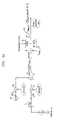
- FIGS. 1A and 1Bare high level block diagrama of a Doppler-corrected rake finger structure used in a communications receiver of the present invention.
- FIG. 2is a high level flow chart illustrating basic operation of the method used with communications receiver of the present invention.
- FIGS. 3A , 3 B, and 3 Care detailed block diagrams of the Doppler-corrected rake finger structure shown in FIGS. 1A and 1B .
- the present inventionadvantageously removes the Doppler frequency shift in a communications receiver, such as the illustrated rake receiver 10 , using differential detection.
- a communications receiversuch as the illustrated rake receiver 10
- differential detectionAs is well known, third generation mobile systems must support mobile speeds up to 500 Km/Hr, which incurs a large Doppler frequency shift.
- the architecture and circuit of the present inventionuses differential detection and removes the Doppler frequency shift in the rake receiver 10 .
- the type of spread spectrum communications signalis a direct sequence spread spectrum signal, such as a code division multiple access (CDMA) communications signal.
- CDMAcode division multiple access
- W-CDMA3G wideband CDMA
- itincludes a common pilot channel and dedicated physical channel, such as for data, e.g., a data channel.
- the present inventionuses mathematical derivations and associated algorithms with the common pilot channel to estimate the Doppler frequency and use that Doppler frequency estimation to remove, i.e., cancel, the Doppler frequency for the dedicated physical channel of the wideband code division multiple access (W-CDMA) communications signal.
- FIGS. 1A and 1Ba high level block diagram of a rake receiver 10 having a Doppler-corrected rake finger structure is illustrated.
- the signalis down converted 10 a and descrambled 10 b .
- the signalis next split at baseband via a mixer and phase shift circuit 11 into in-phase (I) and quadrature (Q) components and into in-phase (I) first and second pats and quadrature (Q) first and second paths.
- the first pathincludes a pilot channel rake section 12 having I and Q Doppler estimation channels 14 , 16 for estimating the Doppler change in frequency based on a common pilot channel.
- a data channel rake section 18has two parts 20 , 22 , which receive the data from the dedicated physical channel and cancels the Doppler frequency shift. To have data recovered, the rake section 12 receives the pilot from the common pilot channel and uses it to estimate the Doppler frequency shift.
- Each I and Q data channel 20 , 22includes a delay circuit 24 for receiving respective I and Q signals split from the spread spectrum communications signal at baseband.
- Sine and cosine branches 26 , 28have mixers 30 , 32 that receive and multiply at the mixers 30 , 32 the Doppler frequency change in frequency that is estimated from the pilot channel rake section 12 .
- the sine branch 26includes phase shift circuit 34 for shifting the delayed signal 90°, imparting the necessary phase change for the sine branch.
- An addition/subtraction circuit 36adds and subtracts the necessary multiplied product received from respective sine and cosine branches 26 , 28 .
- a mixer 38receives the channelization code and an integration circuit 40 to cancel the Doppler error over every symbol. It integrates over one symbol time, which is equal to the spreading factor multiplied by the chip time (SF ⁇ T c ).
- Each I and Q Doppler estimation channel 14 , 16includes a mixer 42 for receiving the I and Q portions of the spread spectrum communications signal at baseband and a respective I, Q channelization code.
- Each I and Q Doppler estimation channelalso includes an integrator 44 , a sample circuit 46 , and a delay circuit 48 , including a phase shifter 50 and multiplier and add/sum circuit 52 .
- a divide circuit 53 for the produced Ak and Bk signal componentsis subject to an arc tangent function in arc tangent circuit 54 , together with a sine and phase circuit 56 to produce the estimated sine and cosine Doppler frequency correction components. Further details of the circuit are shown and explained with reference to FIG. 3 below.
- FIG. 2illustrates a high level flow chart of the sequence of steps of the present invention, where a spread spectrum communication signal is received in a receiver (block 100 ).
- the spread spectrum communication signalhas a dedicated physical channel and common pilot channel.
- a channelization codeis multiplied (mixed) into respective in-phase (I) and quadrature (Q) channels (block 102 ), summed over a symbol period (block 104 ) and sampled to obtain respective I and Q sampled values (block 106 ).
- the channelization code I/Qis mixed for the pilot channels (block 108 ). These values are summed over the symbol period (block 110 ) and then sampled to obtain I/Q samples (block 112 ).
- CPICHcommon pilot channel
- DPCHdedicated physical channel
- r ( t )⁇ square root over (2) ⁇ p ⁇ ( t ) a 1 ( t ) C 1 ( t )sin(2 ⁇ ft+ ⁇ ( t ))+ n 1 ( t )+ ⁇ square root over (2) ⁇ p ⁇ ( t ) a q ( t ) C Q ( t )cos(2 ⁇ ft+ ⁇ ( t ))+ n Q ( t ) Equation 1
- pis the signal power.
- C 1 (t) and C Q (t)are the channelization codes for the I and Q channels respectively, while ⁇ (t) is the fading amplitude.
- the systemuses the common pilot to estimate the frequency error, a I (t) and a Q (t) are symbol data. It should be understood, however, that the system can be extended to using the pilot pattern in the dedicated common control physical channel also.
- the signalis sampled.
- the sampled values I k and Q kare given as follows. For the explanatory purposes in the following equation, the noise terms are ignored.
- the ⁇ f estimateis used to remove the frequency error due to the Doppler shift and imperfect down conversion.
- Equation 7the frequency-corrected data is obtained.
- the phase error ⁇ (t) ⁇is over the symbol period. Therefore, it can be alleviated using the simple channel estimation.
- the channelization codeis multiplied for the channel and accumulated over SF ⁇ T c , i.e., the symbol period.
- FIGS. 3A through 3Cshow a more detailed block circuit diagram of the rake finger structure shown in FIG. 1 .
- the phase error introduced due to the imperfect acquisition and trackingis considered in ⁇ (t), which can be alleviated via simple averaged channel estimation,
- ⁇ (t)which can be alleviated via simple averaged channel estimation.
- the spread spectrum communications signal after down conversionis received within the RF receive circuitry 11 where it is split into two signals and mixed in mixers 200 , 201 with signals produced from the appropriate sine (2 ⁇ f c T) and 90° phase shift circuits 202 , 203 to form the respective I and Q baseband signals. These signals, in turn, are again split as described before.
- the signalis delayed by the delay circuit 24 and then split into sine, cosine branches, where on sine branch it is rotated 90°.
- the two signalsenter the addition/subtraction circuit 36 and are combined and mixed with the channelization code in mixer 38 for the data channel and integrated over SF ⁇ Tc period of time.
- the signalis sampled at circuit 210 to form the Doppler cancelled data.
- the signalsenter the mixers 42 where the respective I or Q channel components are mixed with the pilot channelization code and then integrated, sampled, delayed and 90° phase shifted. Part of the sampled signal is cross-coupled into a pair of mixer/multipliers 212 that receive signals from the delay circuit. The signals from the delay circuit also are cross-coupled into a second pair of mixer/multipliers 214 that receive the 90° phase shift signal. These are then received within respective addition/subtraction circuits 216 producing signals Ak, Bk, which are received and divided by the dividing circuit 53 . The arc tangent is taken in circuit 54 .
- the mixer/multiplier 230receives the signal and mixes input 1/NT c , which product is received within a sine logic circuit 232 where the estimated sine Doppler cancellation signal and the cosine cancellation signal (after entering the 90° phase shift circuit 234 ) is obtained. These resultant values are used to cancel the Doppler as described above.
Landscapes
- Engineering & Computer Science (AREA)
- Computer Networks & Wireless Communication (AREA)
- Signal Processing (AREA)
- Digital Transmission Methods That Use Modulated Carrier Waves (AREA)
- Mobile Radio Communication Systems (AREA)
Abstract
Description
r(t)=√{square root over (2)}pα(t)a1(t)C1(t)sin(2πΔft+θ(t))+n1(t)+√{square root over (2)}pα(t)aq(t)CQ(t)cos(2πΔft+θ(t))+nQ(t)
Ik90°=√{square root over (2)}pαka1k[sin(2πΔfkNTc+θ)−sin(2πΔf(k−1)NTc+θ]
Qk90°=√{square root over (2)}pαkaQk[cos (2πΔfkNTc+θ)−cos(2πΔf(k−1)NTc+θ] Equation 3
Ak=IkQk+1−QkIk+1=sin(2πΔf(2NTc))−2sin(2πΔfNTc)=2 sin(2πΔfNTc)[cos2πΔfNTc−]
Bk=IkQ90°k−1−QkI90°k+1=2 cos2(2πΔfNTc)−2cos(2πΔfNTc)=2cos(2πΔfNTc)[cos 2πΔfNTc−1] Equation 4
r1(t)=√{square root over (2)}pα(t)a1(t)C1(t)sin(2πΔft+θ(t))+n1(t)
rQ(t)=√{square root over (2)}pα(t)aQ(t)CQ1(t)cos(2πΔft+θ(t))+nQ(t) Equation 6
X1(t)=r1(t)·cos2πΔft−r190°(t)·sin 2πΔf=√{square root over (2)}pα(t)a1(t)C1(t)sin(θ(t))+nX1(t)
XQ(t)=rQ(t)·cos 2πΔft−rQ90°(t)·sin 2πΔf=√{square root over (2)}pα(t)aQ(t)CQ(t)cos(θ(t)+nXq(t) Equation 7
Claims (24)
Priority Applications (3)
| Application Number | Priority Date | Filing Date | Title |
|---|---|---|---|
| US09/841,487US7035315B2 (en) | 2001-04-24 | 2001-04-24 | Doppler corrected communications receiver and method of removing doppler frequency shift |
| EP02252086AEP1253724A1 (en) | 2001-04-24 | 2002-03-22 | Removing Doppler shift from a spread-spectrum signal |
| JP2002106746AJP2002344351A (en) | 2001-04-24 | 2002-04-09 | Method and communication receiver for removing doppler frequency shift in spread spectrum communication signal |
Applications Claiming Priority (1)
| Application Number | Priority Date | Filing Date | Title |
|---|---|---|---|
| US09/841,487US7035315B2 (en) | 2001-04-24 | 2001-04-24 | Doppler corrected communications receiver and method of removing doppler frequency shift |
Publications (2)
| Publication Number | Publication Date |
|---|---|
| US20020181626A1 US20020181626A1 (en) | 2002-12-05 |
| US7035315B2true US7035315B2 (en) | 2006-04-25 |
Family
ID=25284998
Family Applications (1)
| Application Number | Title | Priority Date | Filing Date |
|---|---|---|---|
| US09/841,487Expired - LifetimeUS7035315B2 (en) | 2001-04-24 | 2001-04-24 | Doppler corrected communications receiver and method of removing doppler frequency shift |
Country Status (3)
| Country | Link |
|---|---|
| US (1) | US7035315B2 (en) |
| EP (1) | EP1253724A1 (en) |
| JP (1) | JP2002344351A (en) |
Cited By (4)
| Publication number | Priority date | Publication date | Assignee | Title |
|---|---|---|---|---|
| US20050009544A1 (en)* | 2003-04-04 | 2005-01-13 | Mitsubishi Denki Kabushiki Kaisha | Method for efficient equalization in a telecommunication system including at least one mobile transceiver |
| US20050271000A1 (en)* | 2002-09-27 | 2005-12-08 | Tekefonaktiebolaget L M Ericsson (Publ) | Evaluating orthogonal codes transmitted in a wireless communications network |
| US20060193409A1 (en)* | 2005-02-28 | 2006-08-31 | Chou Shaohan J | Method and apparatus for compensation of doppler induced carrier frequency offset in a digital receiver system |
| US20090285266A1 (en)* | 2008-05-13 | 2009-11-19 | Fujitsu Limited | Rake receiving device, base station apparatus, reception control method, and reception control program |
Families Citing this family (8)
| Publication number | Priority date | Publication date | Assignee | Title |
|---|---|---|---|---|
| US7596190B2 (en)* | 2002-04-01 | 2009-09-29 | Qualcomm Incorporated | System, method, and apparatus for correction of code doppler shift |
| CA2503694A1 (en)* | 2002-11-22 | 2004-06-10 | Interdigital Technology Corporation | Channel gain estimation in a rake receiver |
| US7599453B2 (en)* | 2005-04-21 | 2009-10-06 | Telefonaktiebolaget L M Ericsson (Publ) | Doppler spread estimation for OFDM systems |
| KR101488787B1 (en)* | 2008-07-08 | 2015-02-03 | 삼성전자주식회사 | Apparatus and method for estimating doppler frequency in mobile communication terminal |
| US8477828B2 (en)* | 2008-12-02 | 2013-07-02 | Infineon Technologies Ag | Adaptive correlation for detection of a high-frequency signal |
| US9647867B2 (en)* | 2015-06-19 | 2017-05-09 | Texas Instruments Incorporated | Wideband IQ mismatch correction for direct down-conversion receiver |
| US10601459B1 (en)* | 2018-11-02 | 2020-03-24 | Cisco Technology, Inc. | Efficient handling of clock offset in spread spectrum decoders |
| CN111060920B (en)* | 2019-12-18 | 2023-03-24 | 重庆大学 | Method for eliminating Doppler error of frequency modulation continuous wave laser ranging system |
Citations (15)
| Publication number | Priority date | Publication date | Assignee | Title |
|---|---|---|---|---|
| US5007068A (en)* | 1988-06-07 | 1991-04-09 | The United States Of America As Represented By The Administrator Of The National Aeronautics And Space Administration | Doppler-corrected differential detection system |
| WO1996010879A1 (en) | 1994-10-04 | 1996-04-11 | Motorola Inc. | Method and apparatus for coherent communication reception in a spread-spectrum communication system |
| US5640431A (en) | 1995-03-10 | 1997-06-17 | Motorola, Inc. | Method and apparatus for offset frequency estimation for a coherent receiver |
| US5659573A (en) | 1994-10-04 | 1997-08-19 | Motorola, Inc. | Method and apparatus for coherent reception in a spread-spectrum receiver |
| US5691974A (en) | 1995-01-04 | 1997-11-25 | Qualcomm Incorporated | Method and apparatus for using full spectrum transmitted power in a spread spectrum communication system for tracking individual recipient phase, time and energy |
| EP0898379A2 (en) | 1997-08-20 | 1999-02-24 | Matsushita Electric Industrial Co., Ltd. | Code division multiple access communication with pilot aided detection |
| US5894473A (en) | 1996-02-29 | 1999-04-13 | Ericsson Inc. | Multiple access communications system and method using code and time division |
| US5910950A (en) | 1996-08-16 | 1999-06-08 | Lucent Technologies Inc. | Demodulator phase correction for code division multiple access receiver |
| US6085104A (en) | 1998-03-25 | 2000-07-04 | Sharp Laboratories Of America, Inc. | Pilot aided, time-varying finite impulse response, adaptive channel matching receiving system and method |
| US6141374A (en) | 1998-10-14 | 2000-10-31 | Lucent Technologies Inc. | Method and apparatus for generating multiple matched-filter PN vectors in a CDMA demodulator |
| WO2000065797A1 (en) | 1999-04-23 | 2000-11-02 | Qualcomm Incorporated | Method and apparatus for frequency offset correction |
| US6163563A (en) | 1996-12-31 | 2000-12-19 | Lucent Technologies Inc. | Digital communication system for high-speed complex correlation |
| US6678314B2 (en)* | 1999-12-30 | 2004-01-13 | Nokia Corporation | Spreading factor determination |
| US6680969B1 (en)* | 1999-03-22 | 2004-01-20 | Ericsson, Inc. | Methods for estimating doppler spreads including autocorrelation function hypotheses and related systems and receivers |
| US6700919B1 (en)* | 1999-11-30 | 2004-03-02 | Texas Instruments Incorporated | Channel estimation for communication system using weighted estimates based on pilot data and information data |
Family Cites Families (1)
| Publication number | Priority date | Publication date | Assignee | Title |
|---|---|---|---|---|
| US5715276A (en)* | 1996-08-22 | 1998-02-03 | Golden Bridge Technology, Inc. | Symbol-matched filter having a low silicon and power requirement |
- 2001
- 2001-04-24USUS09/841,487patent/US7035315B2/ennot_activeExpired - Lifetime
- 2002
- 2002-03-22EPEP02252086Apatent/EP1253724A1/ennot_activeCeased
- 2002-04-09JPJP2002106746Apatent/JP2002344351A/enactivePending
Patent Citations (16)
| Publication number | Priority date | Publication date | Assignee | Title |
|---|---|---|---|---|
| US5007068A (en)* | 1988-06-07 | 1991-04-09 | The United States Of America As Represented By The Administrator Of The National Aeronautics And Space Administration | Doppler-corrected differential detection system |
| WO1996010879A1 (en) | 1994-10-04 | 1996-04-11 | Motorola Inc. | Method and apparatus for coherent communication reception in a spread-spectrum communication system |
| US5659573A (en) | 1994-10-04 | 1997-08-19 | Motorola, Inc. | Method and apparatus for coherent reception in a spread-spectrum receiver |
| US5691974A (en) | 1995-01-04 | 1997-11-25 | Qualcomm Incorporated | Method and apparatus for using full spectrum transmitted power in a spread spectrum communication system for tracking individual recipient phase, time and energy |
| US5640431A (en) | 1995-03-10 | 1997-06-17 | Motorola, Inc. | Method and apparatus for offset frequency estimation for a coherent receiver |
| US5894473A (en) | 1996-02-29 | 1999-04-13 | Ericsson Inc. | Multiple access communications system and method using code and time division |
| US5910950A (en) | 1996-08-16 | 1999-06-08 | Lucent Technologies Inc. | Demodulator phase correction for code division multiple access receiver |
| US6163563A (en) | 1996-12-31 | 2000-12-19 | Lucent Technologies Inc. | Digital communication system for high-speed complex correlation |
| EP0898379A2 (en) | 1997-08-20 | 1999-02-24 | Matsushita Electric Industrial Co., Ltd. | Code division multiple access communication with pilot aided detection |
| US6085104A (en) | 1998-03-25 | 2000-07-04 | Sharp Laboratories Of America, Inc. | Pilot aided, time-varying finite impulse response, adaptive channel matching receiving system and method |
| US6141374A (en) | 1998-10-14 | 2000-10-31 | Lucent Technologies Inc. | Method and apparatus for generating multiple matched-filter PN vectors in a CDMA demodulator |
| US6680969B1 (en)* | 1999-03-22 | 2004-01-20 | Ericsson, Inc. | Methods for estimating doppler spreads including autocorrelation function hypotheses and related systems and receivers |
| WO2000065797A1 (en) | 1999-04-23 | 2000-11-02 | Qualcomm Incorporated | Method and apparatus for frequency offset correction |
| US6363102B1 (en)* | 1999-04-23 | 2002-03-26 | Qualcomm Incorporated | Method and apparatus for frequency offset correction |
| US6700919B1 (en)* | 1999-11-30 | 2004-03-02 | Texas Instruments Incorporated | Channel estimation for communication system using weighted estimates based on pilot data and information data |
| US6678314B2 (en)* | 1999-12-30 | 2004-01-13 | Nokia Corporation | Spreading factor determination |
Non-Patent Citations (1)
| Title |
|---|
| Glisic, Savo G. et al., "Design Study For A CDMA-Based LEO Satellite Network: Downlink System Level Parameters," IEEE Journal on Selected Areas in Communications, vol. 14, No. 9, Dec. 9, 1996. |
Cited By (6)
| Publication number | Priority date | Publication date | Assignee | Title |
|---|---|---|---|---|
| US20050271000A1 (en)* | 2002-09-27 | 2005-12-08 | Tekefonaktiebolaget L M Ericsson (Publ) | Evaluating orthogonal codes transmitted in a wireless communications network |
| US7653021B2 (en)* | 2002-09-27 | 2010-01-26 | Telefonaktiebolaget Lm Ericsson (Publ0 | Evaluating orthogonal codes transmitted in a wireless communications network |
| US20050009544A1 (en)* | 2003-04-04 | 2005-01-13 | Mitsubishi Denki Kabushiki Kaisha | Method for efficient equalization in a telecommunication system including at least one mobile transceiver |
| US8290018B2 (en)* | 2003-04-04 | 2012-10-16 | Mitsubishi Denki Kabushiki Kaisha | Method for efficient equalization in a telecommunication system including at least one mobile transceiver |
| US20060193409A1 (en)* | 2005-02-28 | 2006-08-31 | Chou Shaohan J | Method and apparatus for compensation of doppler induced carrier frequency offset in a digital receiver system |
| US20090285266A1 (en)* | 2008-05-13 | 2009-11-19 | Fujitsu Limited | Rake receiving device, base station apparatus, reception control method, and reception control program |
Also Published As
| Publication number | Publication date |
|---|---|
| JP2002344351A (en) | 2002-11-29 |
| EP1253724A1 (en) | 2002-10-30 |
| US20020181626A1 (en) | 2002-12-05 |
Similar Documents
| Publication | Publication Date | Title |
|---|---|---|
| US7167456B2 (en) | Apparatus for estimating propagation path characteristics | |
| US5237587A (en) | Pseudo-noise modem and related digital correlation method | |
| US7889782B2 (en) | Joint de-spreading and frequency correction using a correlator | |
| US7035315B2 (en) | Doppler corrected communications receiver and method of removing doppler frequency shift | |
| US5930305A (en) | Signal demodulation and diversity combining in a communications system using orthogonal modulation | |
| US6289061B1 (en) | Wideband frequency tracking system and method | |
| JP3462364B2 (en) | RAKE receiver in direct spread CDMA transmission system | |
| US6307850B1 (en) | CDMA radio transmission system | |
| US6094449A (en) | Spread spectrum communication synchronization acquisition decoding apparatus | |
| US6728301B1 (en) | System and method for automatic frequency control in spread spectrum communications | |
| US7248622B2 (en) | Low-power code division multiple access receiver | |
| US5594755A (en) | Apparatus for use in equipment providing a digital radio link between a fixed radio unit and a mobile radio unit | |
| US7003020B2 (en) | Selection of multiple propagation paths by successive removal and detection of high autocorrelations | |
| GB2290010A (en) | Phase ambiguity resolution in direct sequence spread spectrum modulation | |
| KR100393647B1 (en) | Spectrum spread communication synchronization establishing method and apparatus using frequency offset and receiver with the same | |
| US5267260A (en) | Spread spectrum receiver using the code division multiple access mode | |
| US6577674B1 (en) | Channel compensator for DS-CDMA receiver | |
| US6233272B1 (en) | Spread spectrum communication receiver | |
| JP2002290254A (en) | Direct conversion receiver | |
| US6850558B1 (en) | Spread spectrum receiver | |
| CN1613195B (en) | Rake receiver with individual finger compensator(s) and related method | |
| US7443934B2 (en) | Method and apparatus for detecting signals, and transmitting apparatus and receiving apparatus using the same | |
| JP3417024B2 (en) | Pilot signal detection circuit | |
| KR20020001138A (en) | Apparatus for automatic frequency controlling in W-CDMA receiver | |
| JPH08331011A (en) | Receiver for spread communication system |
Legal Events
| Date | Code | Title | Description |
|---|---|---|---|
| AS | Assignment | Owner name:LUCENT TECHNOLOGIES INC., NEW JERSEY Free format text:ASSIGNMENT OF ASSIGNORS INTEREST;ASSIGNOR:SUNG, PO-AN;REEL/FRAME:012262/0746 Effective date:20010926 | |
| STCF | Information on status: patent grant | Free format text:PATENTED CASE | |
| FEPP | Fee payment procedure | Free format text:PAYOR NUMBER ASSIGNED (ORIGINAL EVENT CODE: ASPN); ENTITY STATUS OF PATENT OWNER: LARGE ENTITY | |
| FPAY | Fee payment | Year of fee payment:4 | |
| AS | Assignment | Owner name:CREDIT SUISSE AG, NEW YORK Free format text:SECURITY INTEREST;ASSIGNOR:ALCATEL-LUCENT USA INC.;REEL/FRAME:030510/0627 Effective date:20130130 | |
| FPAY | Fee payment | Year of fee payment:8 | |
| AS | Assignment | Owner name:ALCATEL-LUCENT USA INC., NEW JERSEY Free format text:RELEASE BY SECURED PARTY;ASSIGNOR:CREDIT SUISSE AG;REEL/FRAME:033950/0261 Effective date:20140819 | |
| AS | Assignment | Owner name:PROVENANCE ASSET GROUP LLC, CONNECTICUT Free format text:ASSIGNMENT OF ASSIGNORS INTEREST;ASSIGNORS:NOKIA TECHNOLOGIES OY;NOKIA SOLUTIONS AND NETWORKS BV;ALCATEL LUCENT SAS;REEL/FRAME:043877/0001 Effective date:20170912 Owner name:NOKIA USA INC., CALIFORNIA Free format text:SECURITY INTEREST;ASSIGNORS:PROVENANCE ASSET GROUP HOLDINGS, LLC;PROVENANCE ASSET GROUP LLC;REEL/FRAME:043879/0001 Effective date:20170913 Owner name:CORTLAND CAPITAL MARKET SERVICES, LLC, ILLINOIS Free format text:SECURITY INTEREST;ASSIGNORS:PROVENANCE ASSET GROUP HOLDINGS, LLC;PROVENANCE ASSET GROUP, LLC;REEL/FRAME:043967/0001 Effective date:20170913 | |
| MAFP | Maintenance fee payment | Free format text:PAYMENT OF MAINTENANCE FEE, 12TH YEAR, LARGE ENTITY (ORIGINAL EVENT CODE: M1553) Year of fee payment:12 | |
| AS | Assignment | Owner name:NOKIA US HOLDINGS INC., NEW JERSEY Free format text:ASSIGNMENT AND ASSUMPTION AGREEMENT;ASSIGNOR:NOKIA USA INC.;REEL/FRAME:048370/0682 Effective date:20181220 | |
| AS | Assignment | Owner name:ALCATEL-LUCENT USA INC, NEW JERSEY Free format text:CHANGE OF NAME;ASSIGNOR:LUCENT TECHNOLOGIES INC.;REEL/FRAME:050479/0982 Effective date:20081101 | |
| AS | Assignment | Owner name:PROVENANCE ASSET GROUP LLC, CONNECTICUT Free format text:RELEASE BY SECURED PARTY;ASSIGNOR:CORTLAND CAPITAL MARKETS SERVICES LLC;REEL/FRAME:058983/0104 Effective date:20211101 Owner name:PROVENANCE ASSET GROUP HOLDINGS LLC, CONNECTICUT Free format text:RELEASE BY SECURED PARTY;ASSIGNOR:CORTLAND CAPITAL MARKETS SERVICES LLC;REEL/FRAME:058983/0104 Effective date:20211101 Owner name:PROVENANCE ASSET GROUP LLC, CONNECTICUT Free format text:RELEASE BY SECURED PARTY;ASSIGNOR:NOKIA US HOLDINGS INC.;REEL/FRAME:058363/0723 Effective date:20211129 Owner name:PROVENANCE ASSET GROUP HOLDINGS LLC, CONNECTICUT Free format text:RELEASE BY SECURED PARTY;ASSIGNOR:NOKIA US HOLDINGS INC.;REEL/FRAME:058363/0723 Effective date:20211129 | |
| AS | Assignment | Owner name:RPX CORPORATION, CALIFORNIA Free format text:ASSIGNMENT OF ASSIGNORS INTEREST;ASSIGNOR:PROVENANCE ASSET GROUP LLC;REEL/FRAME:059352/0001 Effective date:20211129 | |
| AS | Assignment | Owner name:BARINGS FINANCE LLC, AS COLLATERAL AGENT, NORTH CAROLINA Free format text:PATENT SECURITY AGREEMENT;ASSIGNOR:RPX CORPORATION;REEL/FRAME:063429/0001 Effective date:20220107 |