US7034987B2 - Electrophoretic display device - Google Patents
Electrophoretic display deviceDownload PDFInfo
- Publication number
- US7034987B2 US7034987B2US10/504,707US50470704AUS7034987B2US 7034987 B2US7034987 B2US 7034987B2US 50470704 AUS50470704 AUS 50470704AUS 7034987 B2US7034987 B2US 7034987B2
- Authority
- US
- United States
- Prior art keywords
- particles
- spectral range
- optical spectral
- particle
- light
- Prior art date
- Legal status (The legal status is an assumption and is not a legal conclusion. Google has not performed a legal analysis and makes no representation as to the accuracy of the status listed.)
- Expired - Lifetime
Links
- 239000002245particleSubstances0.000claimsabstractdescription162
- 230000003287optical effectEffects0.000claimsabstractdescription45
- 230000003595spectral effectEffects0.000claimsabstractdescription40
- 238000009826distributionMethods0.000claimsdescription5
- 239000011148porous materialSubstances0.000claimsdescription2
- 239000003086colorantSubstances0.000abstractdescription19
- 230000005684electric fieldEffects0.000abstractdescription6
- 238000010521absorption reactionMethods0.000abstractdescription5
- 230000000694effectsEffects0.000description7
- 239000012530fluidSubstances0.000description5
- 239000000049pigmentSubstances0.000description5
- 230000008447perceptionEffects0.000description3
- 238000001228spectrumMethods0.000description3
- 239000004986Cholesteric liquid crystals (ChLC)Substances0.000description2
- NRCMAYZCPIVABH-UHFFFAOYSA-NQuinacridoneChemical compoundN1C2=CC=CC=C2C(=O)C2=C1C=C1C(=O)C3=CC=CC=C3NC1=C2NRCMAYZCPIVABH-UHFFFAOYSA-N0.000description2
- 239000007788liquidSubstances0.000description2
- 238000004519manufacturing processMethods0.000description2
- 239000000463materialSubstances0.000description2
- TXWSZJSDZKWQAU-UHFFFAOYSA-N2,9-dimethyl-5,12-dihydroquinolino[2,3-b]acridine-7,14-dioneChemical compoundN1C2=CC=C(C)C=C2C(=O)C2=C1C=C(C(=O)C=1C(=CC=C(C=1)C)N1)C1=C2TXWSZJSDZKWQAU-UHFFFAOYSA-N0.000description1
- IAFBRPFISOTXSO-UHFFFAOYSA-N2-[[2-chloro-4-[3-chloro-4-[[1-(2,4-dimethylanilino)-1,3-dioxobutan-2-yl]diazenyl]phenyl]phenyl]diazenyl]-n-(2,4-dimethylphenyl)-3-oxobutanamideChemical compoundC=1C=C(C)C=C(C)C=1NC(=O)C(C(=O)C)N=NC(C(=C1)Cl)=CC=C1C(C=C1Cl)=CC=C1N=NC(C(C)=O)C(=O)NC1=CC=C(C)C=C1CIAFBRPFISOTXSO-UHFFFAOYSA-N0.000description1
- LPDSNGAFAJYVKH-UHFFFAOYSA-N4-(4-aminophenyl)-2,3-dichloroanilineChemical compoundC1=CC(N)=CC=C1C1=CC=C(N)C(Cl)=C1ClLPDSNGAFAJYVKH-UHFFFAOYSA-N0.000description1
- 230000009286beneficial effectEffects0.000description1
- 239000002775capsuleSubstances0.000description1
- 230000003098cholesteric effectEffects0.000description1
- 239000011248coating agentSubstances0.000description1
- 238000000576coating methodMethods0.000description1
- 230000021615conjugationEffects0.000description1
- 239000000839emulsionSubstances0.000description1
- 238000005516engineering processMethods0.000description1
- 230000006870functionEffects0.000description1
- 230000031700light absorptionEffects0.000description1
- 238000000034methodMethods0.000description1
- 238000002156mixingMethods0.000description1
- 239000000203mixtureSubstances0.000description1
- 229920006395saturated elastomerPolymers0.000description1
- 239000002904solventSubstances0.000description1
- 239000000758substrateSubstances0.000description1
- 239000001052yellow pigmentSubstances0.000description1
Images


Classifications
- G—PHYSICS
- G02—OPTICS
- G02F—OPTICAL DEVICES OR ARRANGEMENTS FOR THE CONTROL OF LIGHT BY MODIFICATION OF THE OPTICAL PROPERTIES OF THE MEDIA OF THE ELEMENTS INVOLVED THEREIN; NON-LINEAR OPTICS; FREQUENCY-CHANGING OF LIGHT; OPTICAL LOGIC ELEMENTS; OPTICAL ANALOGUE/DIGITAL CONVERTERS
- G02F1/00—Devices or arrangements for the control of the intensity, colour, phase, polarisation or direction of light arriving from an independent light source, e.g. switching, gating or modulating; Non-linear optics
- G02F1/01—Devices or arrangements for the control of the intensity, colour, phase, polarisation or direction of light arriving from an independent light source, e.g. switching, gating or modulating; Non-linear optics for the control of the intensity, phase, polarisation or colour
- G02F1/165—Devices or arrangements for the control of the intensity, colour, phase, polarisation or direction of light arriving from an independent light source, e.g. switching, gating or modulating; Non-linear optics for the control of the intensity, phase, polarisation or colour based on translational movement of particles in a fluid under the influence of an applied field
- G02F1/166—Devices or arrangements for the control of the intensity, colour, phase, polarisation or direction of light arriving from an independent light source, e.g. switching, gating or modulating; Non-linear optics for the control of the intensity, phase, polarisation or colour based on translational movement of particles in a fluid under the influence of an applied field characterised by the electro-optical or magneto-optical effect
- G02F1/167—Devices or arrangements for the control of the intensity, colour, phase, polarisation or direction of light arriving from an independent light source, e.g. switching, gating or modulating; Non-linear optics for the control of the intensity, phase, polarisation or colour based on translational movement of particles in a fluid under the influence of an applied field characterised by the electro-optical or magneto-optical effect by electrophoresis
- G—PHYSICS
- G02—OPTICS
- G02F—OPTICAL DEVICES OR ARRANGEMENTS FOR THE CONTROL OF LIGHT BY MODIFICATION OF THE OPTICAL PROPERTIES OF THE MEDIA OF THE ELEMENTS INVOLVED THEREIN; NON-LINEAR OPTICS; FREQUENCY-CHANGING OF LIGHT; OPTICAL LOGIC ELEMENTS; OPTICAL ANALOGUE/DIGITAL CONVERTERS
- G02F1/00—Devices or arrangements for the control of the intensity, colour, phase, polarisation or direction of light arriving from an independent light source, e.g. switching, gating or modulating; Non-linear optics
- G02F1/01—Devices or arrangements for the control of the intensity, colour, phase, polarisation or direction of light arriving from an independent light source, e.g. switching, gating or modulating; Non-linear optics for the control of the intensity, phase, polarisation or colour
- G02F1/13—Devices or arrangements for the control of the intensity, colour, phase, polarisation or direction of light arriving from an independent light source, e.g. switching, gating or modulating; Non-linear optics for the control of the intensity, phase, polarisation or colour based on liquid crystals, e.g. single liquid crystal display cells
- G02F1/133—Constructional arrangements; Operation of liquid crystal cells; Circuit arrangements
- G02F1/1333—Constructional arrangements; Manufacturing methods
- G02F1/1343—Electrodes
- G02F1/134309—Electrodes characterised by their geometrical arrangement
- G02F1/134363—Electrodes characterised by their geometrical arrangement for applying an electric field parallel to the substrate, i.e. in-plane switching [IPS]
- G—PHYSICS
- G02—OPTICS
- G02F—OPTICAL DEVICES OR ARRANGEMENTS FOR THE CONTROL OF LIGHT BY MODIFICATION OF THE OPTICAL PROPERTIES OF THE MEDIA OF THE ELEMENTS INVOLVED THEREIN; NON-LINEAR OPTICS; FREQUENCY-CHANGING OF LIGHT; OPTICAL LOGIC ELEMENTS; OPTICAL ANALOGUE/DIGITAL CONVERTERS
- G02F1/00—Devices or arrangements for the control of the intensity, colour, phase, polarisation or direction of light arriving from an independent light source, e.g. switching, gating or modulating; Non-linear optics
- G02F1/01—Devices or arrangements for the control of the intensity, colour, phase, polarisation or direction of light arriving from an independent light source, e.g. switching, gating or modulating; Non-linear optics for the control of the intensity, phase, polarisation or colour
- G02F1/13—Devices or arrangements for the control of the intensity, colour, phase, polarisation or direction of light arriving from an independent light source, e.g. switching, gating or modulating; Non-linear optics for the control of the intensity, phase, polarisation or colour based on liquid crystals, e.g. single liquid crystal display cells
- G02F1/133—Constructional arrangements; Operation of liquid crystal cells; Circuit arrangements
- G02F1/1333—Constructional arrangements; Manufacturing methods
- G02F1/1347—Arrangement of liquid crystal layers or cells in which the final condition of one light beam is achieved by the addition of the effects of two or more layers or cells
- G—PHYSICS
- G02—OPTICS
- G02F—OPTICAL DEVICES OR ARRANGEMENTS FOR THE CONTROL OF LIGHT BY MODIFICATION OF THE OPTICAL PROPERTIES OF THE MEDIA OF THE ELEMENTS INVOLVED THEREIN; NON-LINEAR OPTICS; FREQUENCY-CHANGING OF LIGHT; OPTICAL LOGIC ELEMENTS; OPTICAL ANALOGUE/DIGITAL CONVERTERS
- G02F1/00—Devices or arrangements for the control of the intensity, colour, phase, polarisation or direction of light arriving from an independent light source, e.g. switching, gating or modulating; Non-linear optics
- G02F1/01—Devices or arrangements for the control of the intensity, colour, phase, polarisation or direction of light arriving from an independent light source, e.g. switching, gating or modulating; Non-linear optics for the control of the intensity, phase, polarisation or colour
- G02F1/13—Devices or arrangements for the control of the intensity, colour, phase, polarisation or direction of light arriving from an independent light source, e.g. switching, gating or modulating; Non-linear optics for the control of the intensity, phase, polarisation or colour based on liquid crystals, e.g. single liquid crystal display cells
- G02F1/137—Devices or arrangements for the control of the intensity, colour, phase, polarisation or direction of light arriving from an independent light source, e.g. switching, gating or modulating; Non-linear optics for the control of the intensity, phase, polarisation or colour based on liquid crystals, e.g. single liquid crystal display cells characterised by the electro-optical or magneto-optical effect, e.g. field-induced phase transition, orientation effect, guest-host interaction or dynamic scattering
- G—PHYSICS
- G02—OPTICS
- G02F—OPTICAL DEVICES OR ARRANGEMENTS FOR THE CONTROL OF LIGHT BY MODIFICATION OF THE OPTICAL PROPERTIES OF THE MEDIA OF THE ELEMENTS INVOLVED THEREIN; NON-LINEAR OPTICS; FREQUENCY-CHANGING OF LIGHT; OPTICAL LOGIC ELEMENTS; OPTICAL ANALOGUE/DIGITAL CONVERTERS
- G02F1/00—Devices or arrangements for the control of the intensity, colour, phase, polarisation or direction of light arriving from an independent light source, e.g. switching, gating or modulating; Non-linear optics
- G02F1/01—Devices or arrangements for the control of the intensity, colour, phase, polarisation or direction of light arriving from an independent light source, e.g. switching, gating or modulating; Non-linear optics for the control of the intensity, phase, polarisation or colour
- G02F1/165—Devices or arrangements for the control of the intensity, colour, phase, polarisation or direction of light arriving from an independent light source, e.g. switching, gating or modulating; Non-linear optics for the control of the intensity, phase, polarisation or colour based on translational movement of particles in a fluid under the influence of an applied field
- G02F1/1675—Constructional details
- G02F1/1677—Structural association of cells with optical devices, e.g. reflectors or illuminating devices
- G—PHYSICS
- G02—OPTICS
- G02F—OPTICAL DEVICES OR ARRANGEMENTS FOR THE CONTROL OF LIGHT BY MODIFICATION OF THE OPTICAL PROPERTIES OF THE MEDIA OF THE ELEMENTS INVOLVED THEREIN; NON-LINEAR OPTICS; FREQUENCY-CHANGING OF LIGHT; OPTICAL LOGIC ELEMENTS; OPTICAL ANALOGUE/DIGITAL CONVERTERS
- G02F1/00—Devices or arrangements for the control of the intensity, colour, phase, polarisation or direction of light arriving from an independent light source, e.g. switching, gating or modulating; Non-linear optics
- G02F1/01—Devices or arrangements for the control of the intensity, colour, phase, polarisation or direction of light arriving from an independent light source, e.g. switching, gating or modulating; Non-linear optics for the control of the intensity, phase, polarisation or colour
- G02F1/17—Devices or arrangements for the control of the intensity, colour, phase, polarisation or direction of light arriving from an independent light source, e.g. switching, gating or modulating; Non-linear optics for the control of the intensity, phase, polarisation or colour based on variable-absorption elements not provided for in groups G02F1/015 - G02F1/169
- G02F1/172—Devices or arrangements for the control of the intensity, colour, phase, polarisation or direction of light arriving from an independent light source, e.g. switching, gating or modulating; Non-linear optics for the control of the intensity, phase, polarisation or colour based on variable-absorption elements not provided for in groups G02F1/015 - G02F1/169 based on a suspension of orientable dipolar particles, e.g. suspended particles displays
- G—PHYSICS
- G02—OPTICS
- G02F—OPTICAL DEVICES OR ARRANGEMENTS FOR THE CONTROL OF LIGHT BY MODIFICATION OF THE OPTICAL PROPERTIES OF THE MEDIA OF THE ELEMENTS INVOLVED THEREIN; NON-LINEAR OPTICS; FREQUENCY-CHANGING OF LIGHT; OPTICAL LOGIC ELEMENTS; OPTICAL ANALOGUE/DIGITAL CONVERTERS
- G02F1/00—Devices or arrangements for the control of the intensity, colour, phase, polarisation or direction of light arriving from an independent light source, e.g. switching, gating or modulating; Non-linear optics
- G02F1/01—Devices or arrangements for the control of the intensity, colour, phase, polarisation or direction of light arriving from an independent light source, e.g. switching, gating or modulating; Non-linear optics for the control of the intensity, phase, polarisation or colour
- G02F1/165—Devices or arrangements for the control of the intensity, colour, phase, polarisation or direction of light arriving from an independent light source, e.g. switching, gating or modulating; Non-linear optics for the control of the intensity, phase, polarisation or colour based on translational movement of particles in a fluid under the influence of an applied field
- G02F1/1675—Constructional details
- G02F2001/1678—Constructional details characterised by the composition or particle type
- G—PHYSICS
- G02—OPTICS
- G02F—OPTICAL DEVICES OR ARRANGEMENTS FOR THE CONTROL OF LIGHT BY MODIFICATION OF THE OPTICAL PROPERTIES OF THE MEDIA OF THE ELEMENTS INVOLVED THEREIN; NON-LINEAR OPTICS; FREQUENCY-CHANGING OF LIGHT; OPTICAL LOGIC ELEMENTS; OPTICAL ANALOGUE/DIGITAL CONVERTERS
- G02F2202/00—Materials and properties
- G02F2202/04—Materials and properties dye
Definitions
- the inventionrelates to an electrophoretic display device for generating a colored image, the device comprising picture elements which have a visible area, a medium that is substantially transparent in the optical spectral range, at least two types of independently controllable electrophoretic particles, and means for controlling the distribution of the particles in the medium.
- An electrophoretic display deviceis known from patent application WO99/53373.
- the display devicecomprises picture elements, each element having several types of particles in a suspending fluid, e.g. as shown in FIGS. 5 to 8 of the document.
- the particlesare charged and are therefore controllable by an electric field, which effect is called the electrophoretic effect.
- the suspending fluidfunctions as a medium that permits the particles of different types to travel at different speeds under the influence of the electric field.
- the movement of each type of particlesis controlled by providing electrodes and a suitable pattern of control voltages. Selected particles are moved to a visible area of the picture element.
- Each type of particleshas a specific color, and therefore a specific type of particles at the front surface of the picture element in the visible area result in a specific color of the picture element.
- the picture elementcomprises red (R), green (G) and blue (B) particles.
- the particlesare supposed to be negatively charged, and are first moved to the back end of the picture element by an electric field in a direction transverse to the visible area by a positive voltage between a bottom electrode and a top electrode. Then the voltage is reversed, and the particles start to move to the front of the picture element.
- the red particlesare the fastest, so they arrive first.
- the voltageis then removed from the electrodes, and the red particles are visible because the red component from the incident white light is reflected. The remaining part of the light is absorbed so that the blue and green components of the incident light cannot reach the blue and green particles which are floating lower in the picture element.
- Different colorscan be generated by moving all particles to the front and thereafter removing faster particles to the backside of the picture element. For example yellow could be generated by moving a mix of red and green particles to the front.
- a problem of the known displayis that contrast and brightness of the colors generated are not satisfactory.
- a device as defined in the opening paragraphwhich comprises at least one reservoir located outside the visible area for containing particles that are not in the visible area, each particle type being substantially transparent for a first part of the optical spectral range, being substantially non-back scattering, and being absorbing or reflective for a second part of the optical spectral range, the first and second part together covering the optical spectral range, and the second parts of the optical spectral range of said particle types being substantially non-overlapping.
- the effectis that particles of a specific type are obstructing substantially no light outside the specific second part of the spectral range.
- the light produced by the picture element in the specific second part of the optical spectral rangeis controlled by moving particles of that type to the visible area.
- the intensity of all second parts of the optical spectral rangecan be controlled independently, while no light is absorbed in parts of the spectral range by particles that are needed for controlling other spectral ranges.
- the advantageous effectis that the brightness and contrast for all colors will be high.
- the inventionis also based on the following recognition.
- the inventorhas seen that the known multicolored picture elements can produce mixed colors only at a reduced brightness.
- a primary colori.e. a color that is produced by a single particle type
- a high brightnessmay be achieved because all incident light of that primary color will be reflected by the particles at the front surface of the picture element.
- a mixed colorsuch as yellow in a system having red, green and blue particles is produced by having 50% green and 50% red particles at the surface of the visible area.
- Hence only 50% of the incident lightis reflected and the brightness for yellow is reduced to 50%.
- the inventorhas concluded that the known system is flawed because it uses particles that obstruct, i.e. absorb or scatter light outside the part of the spectrum that is controlled. Particles that do not obstruct prevent the reduced brightness, provided that they are removed from the visible area to the reservoir when they are not needed.
- the non-overlapping second partstogether substantially cover the optical spectral range.
- the particlesare substantially non-scattering due to at least one of the following: due to having a refractive index substantially equal to the refractive index of the electrophoretic medium, due to the size of the particles being smaller than the wavelength of light in the optical spectral range, due to the size of the light absorbing layers/structures in the particle being below an internal wavelength in the particle, the internal wavelength being the wavelength of light in the optical spectral range divided by the refractive index of the particle.
- the advantageis that the contrast is enhanced by the particles being non-scattering.
- the picture elementscomprise color filters in which each picture element color filter absorbs or reflects at least one filtered part of the optical spectral range while the remaining non-filtered part of the optical spectral range substantially corresponds to the range of the optical spectral range covered by said second parts of the particle types in the respective picture element.
- FIG. 1Ashows a prior art picture element of a reflective display in reset mode
- FIG. 1Bshows a prior art picture element of a reflective display in red display mode
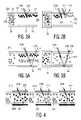
- FIG. 2Ashows a display having obstructing particles in red display mode
- FIG. 2Bshows a display having obstructing particles in yellow display mode
- FIG. 3Ashows a display having non-obstructing particles in red display mode
- FIG. 3Bshows a display having non-obstructing particles in yellow display mode
- FIG. 4shows three cooperating picture elements having color filters
- FIG. 5shows a picture element having a color filter.
- FIG. 1shows a prior art electrophoretic display picture element in different states.
- FIG. 1Ashows a prior art picture element of a reflective display in reset state.
- the picture element 13(also called pixel) is seen from a viewing direction 10 .
- a medium 12comprises electrophoretic particles indicated by the characters R, G, B indicating the colors red, green and blue. Each particle type reflects a particular color, and absorbs the remaining part of the optical spectrum.
- a top electrode 11 and a bottom electrode 14are provided for controlling the movement of the colored particles in the depth direction indicated by ‘d’ transverse to the visible area. The electrodes 11 , 14 do not block the visible area of the picture element.
- the particlesare supposed to be negatively charged, and are moved to the bottom end of the picture element 13 by an electric field in a direction transverse to the visible area by a positive voltage between the bottom electrode 14 and the top electrode 11 . All particles R, G, B are moved to the bottom of the picture element 13 for achieving the reset state.
- the mediumusually is transparent, and therefore in the reset state light of all colors will be reflected resulting in a white color being produced by the picture element.
- the medium in this type of pixelmay also be colored.
- FIG. 1 bshows a prior art picture element of a reflective display in red display state. Selected particles R are located at the visible front surface area of the picture element 13 .
- the specific type R of particles at the front surface of the picture element in the visible arearesults in the specific color red of the picture element.
- the red stateis achieved as follows. After the reset state the voltage is reversed, and the particles start to move to the front of the picture element. Particles have different speeds of movement at certain strength of the electric field. The red particles R are the fastest, so they arrive first at the front surface. The voltage is then removed from the electrodes, and the red particles are visible because the red component from incident white light is reflected. The remaining part of the light is absorbed so that the blue and green components of the incident light cannot reach the blue and green particles which are floating lower in the picture element. Different colors can be generated by moving all particles to the front and thereafter removing faster particles to the backside of the picture element.
- FIG. 2Ashows a display having obstructing particles in red display mode.
- FIG. 2Bshows the same picture element in yellow display mode.
- the Figureis intended to explain the negative effect of using obstructing particles.
- White light 21 Wis shown to be incident on the visible area 23 of the picture element.
- a reservoir 24is shown on the left side of the picture element, which reservoir is not visible for the viewer, e.g. by providing a black mask above the reservoir 24 .
- a top electrode 25 and a bottom electrode 26are positioned in the reservoir to control the movement of the particles.
- a top electrode 27 and a bottom electrode 28are positioned in the visible area 23 to control the movement of the particles.
- Positive and negative voltagesare applied to the various electrodes 25 , 26 , 27 , 28 to independently control the movement of the different types of particles.
- the pixelpreferably is placed on a black background.
- the picture elementis shown in red display state. Red light 21 R is shown to be reflected by the red particles 22 R, which are located in the visible area. The blue particles 22 B and the green particles 22 G are located in the reservoir.
- the picture elementis shown in yellow display state. Red light 21 R and green light 21 G is shown to be reflected by the red particles 22 R and 22 G, which are located in the visible area. The blue particles 22 B and some green particles 22 G and red particles 22 R are located in the reservoir.
- Particles used in existing electrophoretic display conceptsobscure other particles, and colors are made by having different particle species near the top electrode where there is a limited viewing area available.
- electrophoretic displays based on obscuring particlesit is not possible to produce any color over the full pixel area. This results in a considerable loss of (color) brightness.
- FIG. 3Ashows a display having non-obstructing particles in red display state.
- FIG. 3Bshows a display having non-obstructing particles in yellow display state.
- FIG. 3shows a picture element according to the invention.
- the pixel of the electrophoretic displayhas three non-obstructing particle species in a suspending medium.
- the mediummay for example be a transparent fluid or a gas.
- the particle speciesare absorbing for red indicated as cyan 31 C, absorbing green indicated as species magenta 31 M and absorbing blue indicated as yellow 31 Y, whereas each species is basically transparent for the light absorbed in other species.
- the pixelhas a reservoir 24 that is not visible to the observer.
- the pixelhas a visible area which is visible to the viewer and has a reflecting background 34 .
- FIG. 3Ashows the red state where the full visible area can contain both green 31 M and blue 31 Y absorbing particles.
- FIG. 3Bshows the yellow state where the pixel volume contains blue absorbing particles 31 Y. In both cases 100% of the maximum achievable brightness is obtained for the colors produced. Note that in FIG. 3A the same optical perception of the pixel would result when the particle species are distributed more randomly throughout the pixel volume.
- all picture elements shown in FIGS. 3 and 4have a configuration similar to FIG. 2 , including the visible area 23 , the reservoir 24 and electrodes 25 , 26 , 27 , 28 .
- the picture elements according to the inventionmay have a reflector and be used in a reflective system as shown in FIGS. 3 and 4 , but alternatively be used in a transmissive system without a background reflector, e.g. using a backlight unit.
- the electrophoretic display according to the inventionuses particle species that absorb (or reflect) certain wavelengths whereas they are transparent (and basically non-scattering) for light that is absorbed in other particle species. It is noted that back-scattering is to be prevented, but some degree of forward scattering can be beneficial for the contrast. Further it is to be noted particles in this document also includes (micro-) emulsions, i.e. the suspending medium comprises small droplets of a second liquid medium, which droplets are electrophoretically controllable. By moving the particles in/out a pixel volume, color absorption can be controlled or switched on and off at will.
- the full pixel area (and volume)can be used for any particle species. This way the maximum brightness can be achieved for any color.
- the particle speciesare moved electrophoretically into the pixel volume from a connecting reservoir (area or volume) or vice-versa. In the reservoir particles are not visible to the observer.
- the reservoiris adjacent or below the pixel volume. In an embodiment the reservoir is common for all particle species; alternatively each particle species can have its own specific reservoir area or volume.
- the suspending mediumis transparent so that in the absence of particles the observer sees the background through the pixel volume.
- the backgroundcan be a white diffuser, a rough reflector or, when combined with a front scattering film, a specular reflector.
- particle speciesabsorbing for transparent for 1 red green, blue 2 green red, blue 3 blue red, green This set of three particle species results in a full color pixel by using a reservoir from which the particles are drawn into the pixel volume. Without particles, the background is visible through the pixel volume. The background is reflecting for all colors. The reflection can be specular, diffuse or any combination.
- top filters or an additional ‘black’ absorbing particle speciescan be used to enhance the contrast.
- the ‘black’ particlesare absorbing in a substantial part of the optical spectral range, including an overlap with at least some of the second parts.
- the white stateis produced by removing all particles from the pixel volume into the reservoir so that the background becomes visible through the pixel volume.
- Any colorcan be made in the electrophoretic pixel by mixing the right amount of the various particle species in the pixel volume.
- FIG. 4shows three cooperating picture elements having color filters.
- the left pixelhas a cyan filter 41 C
- the middle pixelhas a magenta filter 41 M
- the right pixelhas a yellow filer 41 Y.
- the three sub-pixelshave CMY color filters combined with three different kinds of two-particle electrophoretic sub-pixels based on non-obstructing particle species and constitute a full color system. Particles in the reservoir to the left of the visible area having the filter are not visible to the viewer. Below the pixel volume a reflecting background is placed. The blue state can be achieved in only two of the three sub pixels.
- the yellow color filter element 41 Y on the rightblue light is absorbed and the corresponding pixel is switched to the dark (absorbing) state in order to obtain a saturated blue for the viewer.
- 1 ⁇ 3 of the display areacannot be used for blue.
- the total color brightnessis 67% of the maximum achievable color brightness.
- each sub-pixelonly needs to control two types of particles, which is easier to manufacture and faster in response.
- electrophoretic pixelsare combined with a spatially separated subtractive color filter.
- only two particles speciesare required per pixel to produce a full color display as shown in FIG. 4 .
- the optical properties of the particlesare chosen depending on the color absorbed in the overlying color filter element. The table below gives an example for particles that can be combined in an electrophoretic pixel underlying a cyan color filter element.
- CMY color filter displayabsorbing for transparent for cyan color filter element red green, blue particle 1 green (red) blue particle 2 blue (red) green
- the cyan color filter elementalways absorbs red light so the combination given in the table cannot yield a red pixel.
- Magenta and yellow color filter elementscan be combined with other electrophoretic pixels to yield red.
- CMY color filter displayonly two out of the three CMY color filter elements can be used to yield a certain primary color (red, green, blue). This means that 1 ⁇ 3 of the incoming light is lost for color production.
- a color brightness of 2 ⁇ 3 of the maximal color brightnesscan be achieved, and it requires only two particle species.
- the whole pixel volumedetermines the optical perception of a pixel.
- the perceptionis rather independent of the internal distribution of the particle species in the pixel volume. Random and ordered distributions may give the same optical appearance.
- the reservoircan be partially shielded from the pixel volume by means of a wall.
- Each pixelcan have its own reservoir but one reservoir can also serve several pixels.
- Electrode structures in the reservoir and pixelallow selectively transporting particle species from the reservoir into the pixel volume.
- the electrode structurescan move particles through lateral or transversal fields or any combination. Particles in the reservoir are not visible to the observer. This can be achieved by means of a black mask, by a black reservoir background or by situating the reservoir beneath the reflecting background of the pixel.
- the reservoirhas to be designed in such a way that it occupies a minimal viewing area.
- Pixel wallscan surround pixels as long as these walls do allow for connections to the reservoir(s).
- Non-obstructing particle speciescan be derived along methods known from the liquid toner, ink and pigment industry, or from electrophotographic technologies.
- Non-obstructing particles that reflect specific parts of the optical spectrumare cholesteric flakes.
- the size of the light absorbing layers/structures in each particleshould be well below the internal wavelength in the article (i.e., the wavelength of the light divided by the refractive index of the particle).
- small (nanometer sized) particlescan be used.
- a larger (porous) particle with a refractive index matched to the solventcan be used.
- Suitable pigment particlescan be acquired from pigment industry, e.g. a diarylide yellow pigment based on dichlorobenzidine (known as Novoperm Yellow HR02 from Clariant), a quinacridone magenta pigment (known as Toner Magenta E 02, or PV Fast Red E5B, or PV Fast Pink E from Clariant), and a phtalocyanine cyan pigment (known as Toner Cyan BG from Clariant), all having particle sizes of 50 to 150 nm (typical values).
- a diarylide yellow pigment based on dichlorobenzidineknown as Novoperm Yellow HR02 from Clariant
- a quinacridone magenta pigmentknown as Toner Magenta E 02, or PV Fast Red E5B, or PV Fast Pink E from Clariant
- a phtalocyanine cyan pigmentknown as Toner Cyan BG from Clariant
- FIG. 5shows a picture element having a color filter. Between two transparent substrates or support plates 50 a suspending fluid and electrophoretic particles are located.
- the Figureshows a picture element having a magenta color filter element 41 M.
- a reservoir 56comprises a substantially transparent or translucent fluid while the auxiliary reservoirs 57 comprise particles, 58 Y and 58 C, which absorb at least blue and at least red respectively.
- the particles 58move to the reservoir 56 .
- the electro-optical components particles, 58 Y and 58 C)are now intermixed within the reservoir 56 .
- the auxiliary reservoirs 57are provided with a black mask 59 .
- an embodiment of the picture elementhas no filter element 41 M, but only at least two types of particles.
- a number of additional reservoirsmay be used for different types of particles. Further details of configurations for controlling different types of electrophoretic particles using reservoirs and electrodes are described in co-pending patent application EP 01203176.1 (application number of PHNL 010567).
- the particlesare not fully mobile or may be partially fixed, for instance a working device can be based on a Cholesteric Liquid Crystal material of two different colors in which switching between a transparent or translucent state and a reflective state occurs at different voltages for different colors.
- the CLC materialdoes not necessarily have to be a layer. It can also have the form of encapsulated flakes or particles.
- Layers comprising such capsules or other layers comprising (controllable) reflecting or absorbing particlesdo not need to be completely transparent, as long as the main direction of the light propagation is maintained (translucent or forward scattering layers). Scattering may even be advantageous, provided no significant backscattering occurs, to obtain better absorption, leading to thinner layers.
- the pixel walls 54may be provided with a reflecting or absorbing layer.
- the color filter partsabsorb (or reflect) the colors cyan, magenta and yellow.
- the devicecan also be based on a color filter having colors which absorb (or reflect) other parts of the optical spectral range and adapting the switchable components (layers) accordingly.
- a color filterhaving colors which absorb (or reflect) other parts of the optical spectral range and adapting the switchable components (layers) accordingly.
- the optical spectral rangeon the other hand may include infrared and ultraviolet.
- the above embodiment of the devicecan be understood as having a color filter in which n sub-pixel color filter parts absorb or reflect n parts of the optical spectral range (preferably non-overlapping or having minimal overlap), the device comprising (n ⁇ 1) switchable electro-optical components for controlling absorption or reflection of the remainder of the spectral range in each sub-pixel.
Landscapes
- Physics & Mathematics (AREA)
- Nonlinear Science (AREA)
- Optics & Photonics (AREA)
- General Physics & Mathematics (AREA)
- Chemical & Material Sciences (AREA)
- Electrochemistry (AREA)
- Molecular Biology (AREA)
- Health & Medical Sciences (AREA)
- Chemical Kinetics & Catalysis (AREA)
- Life Sciences & Earth Sciences (AREA)
- Crystallography & Structural Chemistry (AREA)
- Mathematical Physics (AREA)
- Geometry (AREA)
- Electrochromic Elements, Electrophoresis, Or Variable Reflection Or Absorption Elements (AREA)
- Measuring Pulse, Heart Rate, Blood Pressure Or Blood Flow (AREA)
- Control Of Indicators Other Than Cathode Ray Tubes (AREA)
Abstract
Description
| particle species | absorbing for | transparent for |
| 1 | red | green, blue |
| 2 | green | red, blue |
| 3 | blue | red, green |
This set of three particle species results in a full color pixel by using a reservoir from which the particles are drawn into the pixel volume. Without particles, the background is visible through the pixel volume. The background is reflecting for all colors. The reflection can be specular, diffuse or any combination.
| display element | absorbing for | transparent for | ||
| cyan color filter element | red | green, | ||
| particle | ||||
| 1 | green | (red) blue | ||
| particle 2 | blue | (red) green | ||
The cyan color filter element always absorbs red light so the combination given in the table cannot yield a red pixel. Magenta and yellow color filter elements can be combined with other electrophoretic pixels to yield red. In the CMY color filter display, only two out of the three CMY color filter elements can be used to yield a certain primary color (red, green, blue). This means that ⅓ of the incoming light is lost for color production. Hence, a color brightness of ⅔ of the maximal color brightness can be achieved, and it requires only two particle species.
Claims (10)
Applications Claiming Priority (5)
| Application Number | Priority Date | Filing Date | Title |
|---|---|---|---|
| EP02075675.5 | 2002-02-19 | ||
| EP02075675 | 2002-02-19 | ||
| EP02078077.1 | 2002-07-26 | ||
| EP02078077 | 2002-07-26 | ||
| PCT/IB2003/000455WO2003071348A1 (en) | 2002-02-19 | 2003-02-07 | Electrophoretic display device |
Publications (2)
| Publication Number | Publication Date |
|---|---|
| US20050104843A1 US20050104843A1 (en) | 2005-05-19 |
| US7034987B2true US7034987B2 (en) | 2006-04-25 |
Family
ID=27758765
Family Applications (1)
| Application Number | Title | Priority Date | Filing Date |
|---|---|---|---|
| US10/504,707Expired - LifetimeUS7034987B2 (en) | 2002-02-19 | 2003-02-07 | Electrophoretic display device |
Country Status (10)
| Country | Link |
|---|---|
| US (1) | US7034987B2 (en) |
| EP (1) | EP1478973B1 (en) |
| JP (1) | JP4874524B2 (en) |
| KR (1) | KR20040093059A (en) |
| CN (1) | CN1324391C (en) |
| AT (1) | ATE402428T1 (en) |
| AU (1) | AU2003202761A1 (en) |
| DE (1) | DE60322350D1 (en) |
| TW (1) | TW200307170A (en) |
| WO (1) | WO2003071348A1 (en) |
Cited By (46)
| Publication number | Priority date | Publication date | Assignee | Title |
|---|---|---|---|---|
| US20060033676A1 (en)* | 2004-08-10 | 2006-02-16 | Kenneth Faase | Display device |
| US20060050362A1 (en)* | 2003-01-17 | 2006-03-09 | Koninklijke Philips Electronics, N.V. | Eletrophoretic display |
| US20060050378A1 (en)* | 2002-06-13 | 2006-03-09 | Johnson Mark T | Electro-optically active device |
| US20060061530A1 (en)* | 2003-03-05 | 2006-03-23 | Satoshi Yuasa | Color image display panel and driving method thereof |
| US20060152464A1 (en)* | 2005-01-12 | 2006-07-13 | Seiko Epson Corporation | Drive circuit of electro-optical device, driving method of electro-optical device, and electro-optical device having the same |
| US20060152475A1 (en)* | 2003-07-04 | 2006-07-13 | Koninklijke Philips Electronics N.V. | Electrophoretic display panel |
| US20070188848A1 (en)* | 2006-02-10 | 2007-08-16 | Fuji Xerox Co., Ltd. | Image display medium, and image display device equipped with the image display medium |
| US20080024429A1 (en)* | 2006-07-25 | 2008-01-31 | E Ink Corporation | Electrophoretic displays using gaseous fluids |
| US20080036731A1 (en)* | 2006-02-14 | 2008-02-14 | Fuji Xerox Co., Ltd. | Image displaying medium, image display device, writing device and displaying method |
| US20080055234A1 (en)* | 2006-08-30 | 2008-03-06 | Xerox Corporation | Color electrophoretic display device |
| US20080273237A1 (en)* | 2005-05-27 | 2008-11-06 | Koninklijke Philips Electronics, N.V. | Robust Multi Particle System For Color Electrophoretic Displays With Very Low Driving Voltages Comprising a Low Amount of Electrolytes |
| US20090316252A1 (en)* | 2008-04-22 | 2009-12-24 | Advanced Display Technology Ag | Fluidic Multi Color Display |
| US20110085229A1 (en)* | 2009-10-13 | 2011-04-14 | Kent State University | Methods and Apparatus for Controlling Dispersions of Nanoparticles |
| US7957054B1 (en) | 2009-12-21 | 2011-06-07 | Hewlett-Packard Development Company, L.P. | Electro-optical display systems |
| US20110134508A1 (en)* | 2008-08-20 | 2011-06-09 | Ikue Kawashima | Electrophoretic liquid and display device using electrophoretic liquid |
| US20110149376A1 (en)* | 2009-12-21 | 2011-06-23 | Mabeck Jeffrey T | Electro-optical display systems |
| US20120223929A1 (en)* | 2011-03-02 | 2012-09-06 | Seiko Epson Corporation | Electrophoretic display device, driving method of the same, and electronic apparatus |
| US20130176612A1 (en)* | 2008-04-03 | 2013-07-11 | Sipix Imaging, Inc. | Color display devices |
| US8704756B2 (en) | 2010-05-26 | 2014-04-22 | Sipix Imaging, Inc. | Color display architecture and driving methods |
| US8717664B2 (en) | 2012-10-02 | 2014-05-06 | Sipix Imaging, Inc. | Color display device |
| US8786935B2 (en) | 2011-06-02 | 2014-07-22 | Sipix Imaging, Inc. | Color electrophoretic display |
| US8797636B2 (en) | 2012-07-17 | 2014-08-05 | Sipix Imaging, Inc. | Light-enhancing structure for electrophoretic display |
| US8917439B2 (en) | 2012-02-09 | 2014-12-23 | E Ink California, Llc | Shutter mode for color display devices |
| US8964282B2 (en) | 2012-10-02 | 2015-02-24 | E Ink California, Llc | Color display device |
| US8976444B2 (en) | 2011-09-02 | 2015-03-10 | E Ink California, Llc | Color display devices |
| US9013783B2 (en) | 2011-06-02 | 2015-04-21 | E Ink California, Llc | Color electrophoretic display |
| RU2559453C2 (en)* | 2009-12-18 | 2015-08-10 | Налко Компани | Aldehyde-functionalised polymers with improved stability |
| US9116412B2 (en) | 2010-05-26 | 2015-08-25 | E Ink California, Llc | Color display architecture and driving methods |
| US9170468B2 (en) | 2013-05-17 | 2015-10-27 | E Ink California, Llc | Color display device |
| US9285649B2 (en) | 2013-04-18 | 2016-03-15 | E Ink California, Llc | Color display device |
| US9341916B2 (en)* | 2010-05-21 | 2016-05-17 | E Ink Corporation | Multi-color electro-optic displays |
| US9360733B2 (en) | 2012-10-02 | 2016-06-07 | E Ink California, Llc | Color display device |
| US9459510B2 (en) | 2013-05-17 | 2016-10-04 | E Ink California, Llc | Color display device with color filters |
| US9513527B2 (en) | 2014-01-14 | 2016-12-06 | E Ink California, Llc | Color display device |
| US9541814B2 (en) | 2014-02-19 | 2017-01-10 | E Ink California, Llc | Color display device |
| US9646547B2 (en) | 2013-05-17 | 2017-05-09 | E Ink California, Llc | Color display device |
| US9759981B2 (en) | 2014-03-18 | 2017-09-12 | E Ink California, Llc | Color display device |
| US20180088411A1 (en)* | 2016-09-29 | 2018-03-29 | Boe Technology Group Co., Ltd. | Display device |
| US10147366B2 (en) | 2014-11-17 | 2018-12-04 | E Ink California, Llc | Methods for driving four particle electrophoretic display |
| US10162242B2 (en) | 2013-10-11 | 2018-12-25 | E Ink California, Llc | Color display device |
| US10380955B2 (en) | 2014-07-09 | 2019-08-13 | E Ink California, Llc | Color display device and driving methods therefor |
| US10891906B2 (en) | 2014-07-09 | 2021-01-12 | E Ink California, Llc | Color display device and driving methods therefor |
| US11017705B2 (en) | 2012-10-02 | 2021-05-25 | E Ink California, Llc | Color display device including multiple pixels for driving three-particle electrophoretic media |
| WO2021205280A1 (en) | 2020-04-08 | 2021-10-14 | Nexter Systems | Infrared reflectivity control device |
| US11266832B2 (en) | 2017-11-14 | 2022-03-08 | E Ink California, Llc | Electrophoretic active delivery system including porous conductive electrode layer |
| US11938215B2 (en) | 2019-11-27 | 2024-03-26 | E Ink Corporation | Method for operating a benefit agent delivery system comprising microcells having an electrically eroding sealing layer |
Families Citing this family (26)
| Publication number | Priority date | Publication date | Assignee | Title |
|---|---|---|---|---|
| WO2004008238A1 (en)* | 2002-07-17 | 2004-01-22 | Koninklijke Philips Electronics N.V. | In-plane switching electrophoretic display devices |
| US7529019B2 (en) | 2004-07-09 | 2009-05-05 | Koninklijke Philips Electronics N.V. | Light modulator |
| WO2006103605A1 (en)* | 2005-04-01 | 2006-10-05 | Koninklijke Philips Electronics N.V. | Method of manufacturing an electrophoretic display device and an electrophoretic display device |
| KR101143002B1 (en) | 2005-04-11 | 2012-05-08 | 삼성전자주식회사 | Electrophoretic display |
| ITBO20050646A1 (en)* | 2005-10-26 | 2007-04-27 | Silicon Biosystem S R L | METHOD AND APPARATUS FOR CHARACTERIZATION AND COUNTING OF PARTICLES |
| WO2007072355A2 (en)* | 2005-12-20 | 2007-06-28 | Koninklijke Philips Electronics, N.V. | Improved in-plane switching electrophoretic display |
| KR20070121403A (en)* | 2006-06-22 | 2007-12-27 | 삼성전자주식회사 | Electrophoretic display device and manufacturing method thereof |
| US8228290B2 (en)* | 2006-08-17 | 2012-07-24 | Adrea, LLC | Electrophoretic display device with overlapping first and second row and column electrodes |
| CN101512425A (en)* | 2006-08-31 | 2009-08-19 | 皇家飞利浦电子股份有限公司 | Colour reflective display devices |
| US20080088551A1 (en)* | 2006-10-12 | 2008-04-17 | Honeywell International Inc. | Microfluidic prism |
| WO2008065608A1 (en)* | 2006-11-30 | 2008-06-05 | Koninklijke Philips Electronics N.V. | Display device using movement of particles |
| JP2010511200A (en)* | 2006-11-30 | 2010-04-08 | コーニンクレッカ フィリップス エレクトロニクス エヌ ヴィ | Display device using particle movement |
| JP5654236B2 (en)* | 2006-11-30 | 2015-01-14 | コーニンクレッカ フィリップス エヌ ヴェ | Subtractive color display |
| KR101437164B1 (en) | 2007-12-20 | 2014-09-03 | 삼성전자주식회사 | Electrophoretic display element and driving method thereof |
| US9201282B2 (en)* | 2009-07-27 | 2015-12-01 | Hj Forever Patents B.V. | Electrophoretic display device |
| GB2476799A (en)* | 2010-01-07 | 2011-07-13 | Sharp Kk | Reflective display, sensor and camera |
| JP5477124B2 (en)* | 2010-04-05 | 2014-04-23 | セイコーエプソン株式会社 | Electrophoretic display device, electronic apparatus and electrophoretic display body |
| US20120001842A1 (en)* | 2010-06-30 | 2012-01-05 | Stellbrink Joseph W | Display |
| US20130278491A1 (en)* | 2010-12-20 | 2013-10-24 | Hewlett-Packard Development Company, L.P. | Traveling wave dielectrophoretic displays |
| CN102830522B (en)* | 2011-06-17 | 2014-12-24 | 苏州汉朗光电有限公司 | High-brightness high-contrast smectic-phase liquid crystal display screen |
| JP5942394B2 (en)* | 2011-11-22 | 2016-06-29 | ソニー株式会社 | Electrophoretic element and display device |
| CN102540618A (en)* | 2011-12-23 | 2012-07-04 | 乐凯华光印刷科技有限公司 | Manufacturing method for electronic paper display material |
| NL2010936C2 (en) | 2013-06-07 | 2014-09-25 | Hj Forever B V | Electrophoretic display. |
| KR102227477B1 (en)* | 2014-07-08 | 2021-03-15 | 삼성디스플레이 주식회사 | Liquid crystal display device and method of manufacturing the same |
| WO2017110137A1 (en)* | 2015-12-22 | 2017-06-29 | シャープ株式会社 | Photoreflective material and dimmer |
| CN113614631B (en)* | 2019-08-21 | 2024-08-23 | 矽光学有限公司 | Optical element with variable transmissivity and screen with such an optical element |
Citations (7)
| Publication number | Priority date | Publication date | Assignee | Title |
|---|---|---|---|---|
| US3668106A (en)* | 1970-04-09 | 1972-06-06 | Matsushita Electric Industrial Co Ltd | Electrophoretic display device |
| US6017584A (en)* | 1995-07-20 | 2000-01-25 | E Ink Corporation | Multi-color electrophoretic displays and materials for making the same |
| US6504524B1 (en)* | 2000-03-08 | 2003-01-07 | E Ink Corporation | Addressing methods for displays having zero time-average field |
| US20030038772A1 (en)* | 2001-08-23 | 2003-02-27 | De Boer Dirk Kornelis Gerhardus | Electrophoretic display device |
| US6531997B1 (en)* | 1999-04-30 | 2003-03-11 | E Ink Corporation | Methods for addressing electrophoretic displays |
| US6822782B2 (en)* | 2001-05-15 | 2004-11-23 | E Ink Corporation | Electrophoretic particles and processes for the production thereof |
| US6870661B2 (en)* | 2001-05-15 | 2005-03-22 | E Ink Corporation | Electrophoretic displays containing magnetic particles |
Family Cites Families (9)
| Publication number | Priority date | Publication date | Assignee | Title |
|---|---|---|---|---|
| JPH01137240A (en)* | 1987-11-25 | 1989-05-30 | Kinseki Ltd | electrophoretic display device |
| US5325220A (en)* | 1993-03-09 | 1994-06-28 | Research Frontiers Incorporated | Light valve with low emissivity coating as electrode |
| US5930026A (en)* | 1996-10-25 | 1999-07-27 | Massachusetts Institute Of Technology | Nonemissive displays and piezoelectric power supplies therefor |
| JPH1137240A (en)* | 1997-07-16 | 1999-02-12 | Nippon Seiko Kk | Friction roller type transmission |
| WO1999010768A1 (en)* | 1997-08-28 | 1999-03-04 | E-Ink Corporation | Novel addressing schemes for electrophoretic displays |
| US6271823B1 (en)* | 1998-09-16 | 2001-08-07 | International Business Machines Corporation | Reflective electrophoretic display with laterally adjacent color cells using a reflective panel |
| US6144361A (en)* | 1998-09-16 | 2000-11-07 | International Business Machines Corporation | Transmissive electrophoretic display with vertical electrodes |
| EP1162496A1 (en)* | 1999-01-21 | 2001-12-12 | Miwa Science Laboratory Inc. | Image recording medium, image recording/erasing device, and image recording method |
| DE19923906A1 (en)* | 1999-05-26 | 2000-11-30 | Basf Ag | Optically transparent polymeric solid electrolyte |
- 2003
- 2003-02-07EPEP03701672Apatent/EP1478973B1/ennot_activeExpired - Lifetime
- 2003-02-07KRKR10-2004-7012683Apatent/KR20040093059A/ennot_activeWithdrawn
- 2003-02-07AUAU2003202761Apatent/AU2003202761A1/ennot_activeAbandoned
- 2003-02-07WOPCT/IB2003/000455patent/WO2003071348A1/enactiveIP Right Grant
- 2003-02-07JPJP2003570182Apatent/JP4874524B2/ennot_activeExpired - Lifetime
- 2003-02-07DEDE60322350Tpatent/DE60322350D1/ennot_activeExpired - Lifetime
- 2003-02-07CNCNB038041375Apatent/CN1324391C/ennot_activeExpired - Lifetime
- 2003-02-07USUS10/504,707patent/US7034987B2/ennot_activeExpired - Lifetime
- 2003-02-07ATAT03701672Tpatent/ATE402428T1/ennot_activeIP Right Cessation
- 2003-02-14TWTW092103082Apatent/TW200307170A/enunknown
Patent Citations (7)
| Publication number | Priority date | Publication date | Assignee | Title |
|---|---|---|---|---|
| US3668106A (en)* | 1970-04-09 | 1972-06-06 | Matsushita Electric Industrial Co Ltd | Electrophoretic display device |
| US6017584A (en)* | 1995-07-20 | 2000-01-25 | E Ink Corporation | Multi-color electrophoretic displays and materials for making the same |
| US6531997B1 (en)* | 1999-04-30 | 2003-03-11 | E Ink Corporation | Methods for addressing electrophoretic displays |
| US6504524B1 (en)* | 2000-03-08 | 2003-01-07 | E Ink Corporation | Addressing methods for displays having zero time-average field |
| US6822782B2 (en)* | 2001-05-15 | 2004-11-23 | E Ink Corporation | Electrophoretic particles and processes for the production thereof |
| US6870661B2 (en)* | 2001-05-15 | 2005-03-22 | E Ink Corporation | Electrophoretic displays containing magnetic particles |
| US20030038772A1 (en)* | 2001-08-23 | 2003-02-27 | De Boer Dirk Kornelis Gerhardus | Electrophoretic display device |
Cited By (77)
| Publication number | Priority date | Publication date | Assignee | Title |
|---|---|---|---|---|
| US7463407B2 (en)* | 2002-06-13 | 2008-12-09 | Koninklijke Philips Electronics N.V. | Electro-optically active device |
| US20060050378A1 (en)* | 2002-06-13 | 2006-03-09 | Johnson Mark T | Electro-optically active device |
| US7609436B2 (en) | 2002-06-13 | 2009-10-27 | Koninklijke Philips Electronics N.V. | Electro-optically active device |
| US20080088913A1 (en)* | 2002-06-13 | 2008-04-17 | Koninklijke Philips Electronics, N.V. | Electro-optically active device |
| US20060050362A1 (en)* | 2003-01-17 | 2006-03-09 | Koninklijke Philips Electronics, N.V. | Eletrophoretic display |
| US7379228B2 (en)* | 2003-01-17 | 2008-05-27 | Koninklijke Philips Electroncis N.V. | Electrophoretic display |
| US20060061530A1 (en)* | 2003-03-05 | 2006-03-23 | Satoshi Yuasa | Color image display panel and driving method thereof |
| US7859512B2 (en)* | 2003-03-05 | 2010-12-28 | Canon Kabushiki Kaisha | Color image display panel and driving method thereof |
| US20060152475A1 (en)* | 2003-07-04 | 2006-07-13 | Koninklijke Philips Electronics N.V. | Electrophoretic display panel |
| US20060033676A1 (en)* | 2004-08-10 | 2006-02-16 | Kenneth Faase | Display device |
| US20060152464A1 (en)* | 2005-01-12 | 2006-07-13 | Seiko Epson Corporation | Drive circuit of electro-optical device, driving method of electro-optical device, and electro-optical device having the same |
| US8778229B2 (en)* | 2005-05-27 | 2014-07-15 | Koninklijke Philips N.V. | Robust multi particle system for color electrophoretic displays with very low driving voltages comprising a low amount of electrolytes |
| US20080273237A1 (en)* | 2005-05-27 | 2008-11-06 | Koninklijke Philips Electronics, N.V. | Robust Multi Particle System For Color Electrophoretic Displays With Very Low Driving Voltages Comprising a Low Amount of Electrolytes |
| US20070188848A1 (en)* | 2006-02-10 | 2007-08-16 | Fuji Xerox Co., Ltd. | Image display medium, and image display device equipped with the image display medium |
| US7414777B2 (en)* | 2006-02-10 | 2008-08-19 | Fuji Xerox Co., Ltd. | Image display medium, and image display device equipped with the image display medium |
| US20080036731A1 (en)* | 2006-02-14 | 2008-02-14 | Fuji Xerox Co., Ltd. | Image displaying medium, image display device, writing device and displaying method |
| US9129566B2 (en)* | 2006-02-14 | 2015-09-08 | Fuji Xerox Co., Ltd. | Image displaying medium, image display device, writing device and displaying method |
| US20080024429A1 (en)* | 2006-07-25 | 2008-01-31 | E Ink Corporation | Electrophoretic displays using gaseous fluids |
| WO2008014257A3 (en)* | 2006-07-25 | 2008-07-31 | E Ink Corp | Electrophoretic displays using gaseous fluids |
| US7675502B2 (en) | 2006-08-30 | 2010-03-09 | Xerox Corporation | Color electrophoretic display device |
| US20080055234A1 (en)* | 2006-08-30 | 2008-03-06 | Xerox Corporation | Color electrophoretic display device |
| US20130176612A1 (en)* | 2008-04-03 | 2013-07-11 | Sipix Imaging, Inc. | Color display devices |
| US8810899B2 (en)* | 2008-04-03 | 2014-08-19 | E Ink California, Llc | Color display devices |
| US7804634B2 (en)* | 2008-04-22 | 2010-09-28 | Advanced Display Technology Ag | Fluidic multi color display |
| US20090316252A1 (en)* | 2008-04-22 | 2009-12-24 | Advanced Display Technology Ag | Fluidic Multi Color Display |
| US20110134508A1 (en)* | 2008-08-20 | 2011-06-09 | Ikue Kawashima | Electrophoretic liquid and display device using electrophoretic liquid |
| US8441713B2 (en)* | 2008-08-20 | 2013-05-14 | Ricoh Company, Ltd. | Electrophoretic liquid and display device using electrophoretic liquid |
| US20110085229A1 (en)* | 2009-10-13 | 2011-04-14 | Kent State University | Methods and Apparatus for Controlling Dispersions of Nanoparticles |
| US8867121B2 (en)* | 2009-10-13 | 2014-10-21 | Kent State University | Methods and apparatus for controlling dispersions of nanoparticles |
| RU2559453C2 (en)* | 2009-12-18 | 2015-08-10 | Налко Компани | Aldehyde-functionalised polymers with improved stability |
| US7957054B1 (en) | 2009-12-21 | 2011-06-07 | Hewlett-Packard Development Company, L.P. | Electro-optical display systems |
| US8089687B2 (en) | 2009-12-21 | 2012-01-03 | Hewlett-Packard Development Company, L.P. | Electro-optical display systems |
| US20110149376A1 (en)* | 2009-12-21 | 2011-06-23 | Mabeck Jeffrey T | Electro-optical display systems |
| US9341916B2 (en)* | 2010-05-21 | 2016-05-17 | E Ink Corporation | Multi-color electro-optic displays |
| US11733580B2 (en) | 2010-05-21 | 2023-08-22 | E Ink Corporation | Method for driving two layer variable transmission display |
| US12158684B2 (en) | 2010-05-21 | 2024-12-03 | E Ink Corporation | Method for driving two layer variable transmission display |
| US11029576B2 (en) | 2010-05-21 | 2021-06-08 | E Ink Corporation | Method for driving two layer variable transmission display |
| US9989829B2 (en) | 2010-05-21 | 2018-06-05 | E Ink Corporation | Multi-color electro-optic displays |
| US8704756B2 (en) | 2010-05-26 | 2014-04-22 | Sipix Imaging, Inc. | Color display architecture and driving methods |
| US9116412B2 (en) | 2010-05-26 | 2015-08-25 | E Ink California, Llc | Color display architecture and driving methods |
| US8976162B2 (en)* | 2011-03-02 | 2015-03-10 | Seiko Epson Corporation | Electrophoretic display device, driving method of the same, and electronic apparatus |
| US20120223929A1 (en)* | 2011-03-02 | 2012-09-06 | Seiko Epson Corporation | Electrophoretic display device, driving method of the same, and electronic apparatus |
| US9013783B2 (en) | 2011-06-02 | 2015-04-21 | E Ink California, Llc | Color electrophoretic display |
| US8786935B2 (en) | 2011-06-02 | 2014-07-22 | Sipix Imaging, Inc. | Color electrophoretic display |
| US8976444B2 (en) | 2011-09-02 | 2015-03-10 | E Ink California, Llc | Color display devices |
| US8917439B2 (en) | 2012-02-09 | 2014-12-23 | E Ink California, Llc | Shutter mode for color display devices |
| US8797636B2 (en) | 2012-07-17 | 2014-08-05 | Sipix Imaging, Inc. | Light-enhancing structure for electrophoretic display |
| US10332435B2 (en) | 2012-10-02 | 2019-06-25 | E Ink California, Llc | Color display device |
| US9360733B2 (en) | 2012-10-02 | 2016-06-07 | E Ink California, Llc | Color display device |
| US11017705B2 (en) | 2012-10-02 | 2021-05-25 | E Ink California, Llc | Color display device including multiple pixels for driving three-particle electrophoretic media |
| US8964282B2 (en) | 2012-10-02 | 2015-02-24 | E Ink California, Llc | Color display device |
| US8717664B2 (en) | 2012-10-02 | 2014-05-06 | Sipix Imaging, Inc. | Color display device |
| US9285649B2 (en) | 2013-04-18 | 2016-03-15 | E Ink California, Llc | Color display device |
| US9170468B2 (en) | 2013-05-17 | 2015-10-27 | E Ink California, Llc | Color display device |
| US9459510B2 (en) | 2013-05-17 | 2016-10-04 | E Ink California, Llc | Color display device with color filters |
| US9646547B2 (en) | 2013-05-17 | 2017-05-09 | E Ink California, Llc | Color display device |
| US10162242B2 (en) | 2013-10-11 | 2018-12-25 | E Ink California, Llc | Color display device |
| US10234742B2 (en) | 2014-01-14 | 2019-03-19 | E Ink California, Llc | Color display device |
| US10036931B2 (en) | 2014-01-14 | 2018-07-31 | E Ink California, Llc | Color display device |
| US9513527B2 (en) | 2014-01-14 | 2016-12-06 | E Ink California, Llc | Color display device |
| US9541814B2 (en) | 2014-02-19 | 2017-01-10 | E Ink California, Llc | Color display device |
| US9759981B2 (en) | 2014-03-18 | 2017-09-12 | E Ink California, Llc | Color display device |
| US11315505B2 (en) | 2014-07-09 | 2022-04-26 | E Ink California, Llc | Color display device and driving methods therefor |
| US10380955B2 (en) | 2014-07-09 | 2019-08-13 | E Ink California, Llc | Color display device and driving methods therefor |
| US10891906B2 (en) | 2014-07-09 | 2021-01-12 | E Ink California, Llc | Color display device and driving methods therefor |
| US10147366B2 (en) | 2014-11-17 | 2018-12-04 | E Ink California, Llc | Methods for driving four particle electrophoretic display |
| US10431168B2 (en) | 2014-11-17 | 2019-10-01 | E Ink California, Llc | Methods for driving four particle electrophoretic display |
| US10586499B2 (en) | 2014-11-17 | 2020-03-10 | E Ink California, Llc | Electrophoretic display including four particles with different charges and optical characteristics |
| US10891907B2 (en) | 2014-11-17 | 2021-01-12 | E Ink California, Llc | Electrophoretic display including four particles with different charges and optical characteristics |
| US20180088411A1 (en)* | 2016-09-29 | 2018-03-29 | Boe Technology Group Co., Ltd. | Display device |
| US10527884B2 (en)* | 2016-09-29 | 2020-01-07 | Boe Technology Group Co., Ltd. | Display device |
| US11266832B2 (en) | 2017-11-14 | 2022-03-08 | E Ink California, Llc | Electrophoretic active delivery system including porous conductive electrode layer |
| US11938215B2 (en) | 2019-11-27 | 2024-03-26 | E Ink Corporation | Method for operating a benefit agent delivery system comprising microcells having an electrically eroding sealing layer |
| US11938214B2 (en) | 2019-11-27 | 2024-03-26 | E Ink Corporation | Benefit agent delivery system comprising microcells having an electrically eroding sealing layer |
| FR3109219A1 (en)* | 2020-04-08 | 2021-10-15 | Nexter Systems | Infrared reflectivity control device |
| WO2021205280A1 (en) | 2020-04-08 | 2021-10-14 | Nexter Systems | Infrared reflectivity control device |
| AU2021252630B2 (en)* | 2020-04-08 | 2025-04-17 | Cy Cergy Paris Universite | Infrared reflectivity control device |
Also Published As
| Publication number | Publication date |
|---|---|
| WO2003071348A1 (en) | 2003-08-28 |
| CN1633623A (en) | 2005-06-29 |
| AU2003202761A1 (en) | 2003-09-09 |
| KR20040093059A (en) | 2004-11-04 |
| CN1324391C (en) | 2007-07-04 |
| EP1478973A1 (en) | 2004-11-24 |
| US20050104843A1 (en) | 2005-05-19 |
| JP4874524B2 (en) | 2012-02-15 |
| ATE402428T1 (en) | 2008-08-15 |
| JP2005517995A (en) | 2005-06-16 |
| TW200307170A (en) | 2003-12-01 |
| DE60322350D1 (en) | 2008-09-04 |
| EP1478973B1 (en) | 2008-07-23 |
Similar Documents
| Publication | Publication Date | Title |
|---|---|---|
| US7034987B2 (en) | Electrophoretic display device | |
| CN1979320B (en) | Display device | |
| US6727873B2 (en) | Reflective electrophoretic display with stacked color cells | |
| EP1678554B1 (en) | A fast full color electrophoretic display with improved driving | |
| US7274416B2 (en) | Display device | |
| US6271823B1 (en) | Reflective electrophoretic display with laterally adjacent color cells using a reflective panel | |
| US9335454B2 (en) | Color filter and display apparatus including the same | |
| WO2012074792A1 (en) | Multi-color electrophoretic displays | |
| TWI472799B (en) | Display panel | |
| CN110322844A (en) | A kind of electrophoretic display apparatus and its display methods for realizing more grayscale colours | |
| JP2004110041A (en) | Filter for display system, display system, method for filtering light or displaying image | |
| CN106054426A (en) | Grayscale electronics-paper | |
| CN103907149A (en) | Display device | |
| KR20190000184A (en) | Reflective Color Filter And Reflective Display Using The Same | |
| TW202522454A (en) | Electrophoretic device with ambient light sensor and adaptive whiteness restoring and color balancing frontlight | |
| WO2023211867A1 (en) | Color displays configured to convert rgb image data for display on advanced color electronic paper | |
| HK40046654B (en) | Illumination systems for reflective displays | |
| HK1107414A (en) | Display device |
Legal Events
| Date | Code | Title | Description |
|---|---|---|---|
| AS | Assignment | Owner name:KONINKLIJKE PHILIPS ELECTRONICS N.V., NETHERLANDS Free format text:ASSIGNMENT OF ASSIGNORS INTEREST;ASSIGNOR:SCHLANGEN, LUCAS JOSEF MARIA;REEL/FRAME:016137/0694 Effective date:20030915 | |
| STCF | Information on status: patent grant | Free format text:PATENTED CASE | |
| FPAY | Fee payment | Year of fee payment:4 | |
| FPAY | Fee payment | Year of fee payment:8 | |
| AS | Assignment | Owner name:KONINKLIJKE PHILIPS N.V., NETHERLANDS Free format text:CHANGE OF NAME;ASSIGNOR:KONINKLIJKE PHILIPS ELECTRONICS N.V.;REEL/FRAME:039428/0606 Effective date:20130515 | |
| AS | Assignment | Owner name:PHILIPS LIGHTING HOLDING B.V., NETHERLANDS Free format text:ASSIGNMENT OF ASSIGNORS INTEREST;ASSIGNOR:KONINKLIJKE PHILIPS N.V.;REEL/FRAME:040060/0009 Effective date:20160607 | |
| MAFP | Maintenance fee payment | Free format text:PAYMENT OF MAINTENANCE FEE, 12TH YEAR, LARGE ENTITY (ORIGINAL EVENT CODE: M1553) Year of fee payment:12 | |
| AS | Assignment | Owner name:SIGNIFY HOLDING B.V., NETHERLANDS Free format text:CHANGE OF NAME;ASSIGNOR:PHILIPS LIGHTING HOLDING B.V.;REEL/FRAME:050837/0576 Effective date:20190201 |