US7033345B2 - Deflectable microimplant delivery system - Google Patents
Deflectable microimplant delivery systemDownload PDFInfo
- Publication number
- US7033345B2 US7033345B2US10/152,110US15211002AUS7033345B2US 7033345 B2US7033345 B2US 7033345B2US 15211002 AUS15211002 AUS 15211002AUS 7033345 B2US7033345 B2US 7033345B2
- Authority
- US
- United States
- Prior art keywords
- section
- distal
- proximal
- distal end
- proximal section
- Prior art date
- Legal status (The legal status is an assumption and is not a legal conclusion. Google has not performed a legal analysis and makes no representation as to the accuracy of the status listed.)
- Expired - Fee Related, expires
Links
- 238000003780insertionMethods0.000claimsabstractdescription24
- 230000037431insertionEffects0.000claimsabstractdescription24
- 230000000007visual effectEffects0.000claimsdescription13
- 239000004642PolyimideSubstances0.000claimsdescription3
- 229920001721polyimidePolymers0.000claimsdescription3
- 238000002347injectionMethods0.000abstractdescription16
- 239000007924injectionSubstances0.000abstractdescription16
- 239000003814drugSubstances0.000abstractdescription14
- 229940124597therapeutic agentDrugs0.000abstractdescription11
- 239000000463materialSubstances0.000abstractdescription9
- 230000001413cellular effectEffects0.000abstractdescription7
- 230000007246mechanismEffects0.000abstractdescription5
- 230000006835compressionEffects0.000abstractdescription3
- 238000007906compressionMethods0.000abstractdescription3
- 210000004165myocardiumAnatomy0.000description12
- 210000002216heartAnatomy0.000description8
- 210000001519tissueAnatomy0.000description8
- 210000005240left ventricleAnatomy0.000description6
- 238000011282treatmentMethods0.000description6
- 230000002491angiogenic effectEffects0.000description5
- 210000004413cardiac myocyteAnatomy0.000description5
- 208000010125myocardial infarctionDiseases0.000description5
- 230000001225therapeutic effectEffects0.000description5
- 230000008901benefitEffects0.000description4
- 239000003795chemical substances by applicationSubstances0.000description4
- 238000000034methodMethods0.000description4
- 206010061216InfarctionDiseases0.000description3
- 210000001174endocardiumAnatomy0.000description3
- 239000003102growth factorSubstances0.000description3
- 230000007574infarctionEffects0.000description3
- 230000001114myogenic effectEffects0.000description3
- 230000000250revascularizationEffects0.000description3
- 239000000126substanceSubstances0.000description3
- 108050007372Fibroblast Growth FactorProteins0.000description2
- 102000018233Fibroblast Growth FactorHuman genes0.000description2
- 206010019280Heart failuresDiseases0.000description2
- 108010019530Vascular Endothelial Growth FactorsProteins0.000description2
- 102000005789Vascular Endothelial Growth FactorsHuman genes0.000description2
- 208000027418Wounds and injuryDiseases0.000description2
- 239000000853adhesiveSubstances0.000description2
- 230000001070adhesive effectEffects0.000description2
- 210000002376aorta thoracicAnatomy0.000description2
- 238000013459approachMethods0.000description2
- 210000004027cellAnatomy0.000description2
- 230000006378damageEffects0.000description2
- 230000008021depositionEffects0.000description2
- 229940079593drugDrugs0.000description2
- 238000002651drug therapyMethods0.000description2
- 238000002592echocardiographyMethods0.000description2
- 210000002889endothelial cellAnatomy0.000description2
- 208000014674injuryDiseases0.000description2
- 230000004048modificationEffects0.000description2
- 238000012986modificationMethods0.000description2
- 231100000241scarToxicity0.000description2
- 239000000243solutionSubstances0.000description2
- 210000000130stem cellAnatomy0.000description2
- 230000002792vascularEffects0.000description2
- 206010007559Cardiac failure congestiveDiseases0.000description1
- 210000000709aortaAnatomy0.000description1
- 210000001765aortic valveAnatomy0.000description1
- 239000003124biologic agentSubstances0.000description1
- 239000012620biological materialSubstances0.000description1
- 230000017531blood circulationEffects0.000description1
- 230000036770blood supplyEffects0.000description1
- 210000001185bone marrowAnatomy0.000description1
- 210000002798bone marrow cellAnatomy0.000description1
- 210000004556brainAnatomy0.000description1
- 230000001101cardioplegic effectEffects0.000description1
- 230000002612cardiopulmonary effectEffects0.000description1
- 238000004113cell cultureMethods0.000description1
- -1cell culturesSubstances0.000description1
- 230000008859changeEffects0.000description1
- 239000000788chromium alloySubstances0.000description1
- 208000029078coronary artery diseaseDiseases0.000description1
- 210000004351coronary vesselAnatomy0.000description1
- 230000002950deficientEffects0.000description1
- 238000013461designMethods0.000description1
- 230000006866deteriorationEffects0.000description1
- 201000010099diseaseDiseases0.000description1
- 208000037265diseases, disorders, signs and symptomsDiseases0.000description1
- 238000005553drillingMethods0.000description1
- 230000000694effectsEffects0.000description1
- 230000002708enhancing effectEffects0.000description1
- 210000003238esophagusAnatomy0.000description1
- 210000001105femoral arteryAnatomy0.000description1
- 210000003191femoral veinAnatomy0.000description1
- 239000012530fluidSubstances0.000description1
- 238000002594fluoroscopyMethods0.000description1
- 210000001035gastrointestinal tractAnatomy0.000description1
- 239000000499gelSubstances0.000description1
- 230000035876healingEffects0.000description1
- 230000004217heart functionEffects0.000description1
- 238000003384imaging methodMethods0.000description1
- 238000012977invasive surgical procedureMethods0.000description1
- 210000004731jugular veinAnatomy0.000description1
- 210000003734kidneyAnatomy0.000description1
- 210000004185liverAnatomy0.000description1
- 238000004519manufacturing processMethods0.000description1
- 239000003550markerSubstances0.000description1
- 239000004005microsphereSubstances0.000description1
- 238000002324minimally invasive surgeryMethods0.000description1
- 210000003205muscleAnatomy0.000description1
- 210000003098myoblastAnatomy0.000description1
- 230000002107myocardial effectEffects0.000description1
- 210000001087myotubuleAnatomy0.000description1
- 210000000056organAnatomy0.000description1
- 239000008188pelletSubstances0.000description1
- 239000002831pharmacologic agentSubstances0.000description1
- 230000000144pharmacologic effectEffects0.000description1
- 229920000642polymerPolymers0.000description1
- 230000000750progressive effectEffects0.000description1
- 230000008929regenerationEffects0.000description1
- 238000011069regeneration methodMethods0.000description1
- 230000008439repair processEffects0.000description1
- 239000007787solidSubstances0.000description1
- 239000010935stainless steelSubstances0.000description1
- 229910001220stainless steelInorganic materials0.000description1
- 208000024891symptomDiseases0.000description1
- 238000002560therapeutic procedureMethods0.000description1
- 238000002054transplantationMethods0.000description1
- 238000010967transthoracic echocardiographyMethods0.000description1
- 238000002604ultrasonographyMethods0.000description1
Images


Classifications
- A—HUMAN NECESSITIES
- A61—MEDICAL OR VETERINARY SCIENCE; HYGIENE
- A61M—DEVICES FOR INTRODUCING MEDIA INTO, OR ONTO, THE BODY; DEVICES FOR TRANSDUCING BODY MEDIA OR FOR TAKING MEDIA FROM THE BODY; DEVICES FOR PRODUCING OR ENDING SLEEP OR STUPOR
- A61M25/00—Catheters; Hollow probes
- A61M25/0067—Catheters; Hollow probes characterised by the distal end, e.g. tips
- A61M25/0082—Catheter tip comprising a tool
- A61M25/0084—Catheter tip comprising a tool being one or more injection needles
- A—HUMAN NECESSITIES
- A61—MEDICAL OR VETERINARY SCIENCE; HYGIENE
- A61M—DEVICES FOR INTRODUCING MEDIA INTO, OR ONTO, THE BODY; DEVICES FOR TRANSDUCING BODY MEDIA OR FOR TAKING MEDIA FROM THE BODY; DEVICES FOR PRODUCING OR ENDING SLEEP OR STUPOR
- A61M25/00—Catheters; Hollow probes
- A61M25/01—Introducing, guiding, advancing, emplacing or holding catheters
- A61M25/0105—Steering means as part of the catheter or advancing means; Markers for positioning
- A61M25/0133—Tip steering devices
- A61M25/0136—Handles therefor
- A—HUMAN NECESSITIES
- A61—MEDICAL OR VETERINARY SCIENCE; HYGIENE
- A61M—DEVICES FOR INTRODUCING MEDIA INTO, OR ONTO, THE BODY; DEVICES FOR TRANSDUCING BODY MEDIA OR FOR TAKING MEDIA FROM THE BODY; DEVICES FOR PRODUCING OR ENDING SLEEP OR STUPOR
- A61M25/00—Catheters; Hollow probes
- A61M25/0067—Catheters; Hollow probes characterised by the distal end, e.g. tips
- A61M25/0082—Catheter tip comprising a tool
- A61M25/0084—Catheter tip comprising a tool being one or more injection needles
- A61M2025/0089—Single injection needle protruding axially, i.e. along the longitudinal axis of the catheter, from the distal tip
- A—HUMAN NECESSITIES
- A61—MEDICAL OR VETERINARY SCIENCE; HYGIENE
- A61M—DEVICES FOR INTRODUCING MEDIA INTO, OR ONTO, THE BODY; DEVICES FOR TRANSDUCING BODY MEDIA OR FOR TAKING MEDIA FROM THE BODY; DEVICES FOR PRODUCING OR ENDING SLEEP OR STUPOR
- A61M25/00—Catheters; Hollow probes
- A61M25/01—Introducing, guiding, advancing, emplacing or holding catheters
- A61M25/0105—Steering means as part of the catheter or advancing means; Markers for positioning
- A61M25/0133—Tip steering devices
- A61M25/0144—Tip steering devices having flexible regions as a result of inner reinforcement means, e.g. struts or rods
- A—HUMAN NECESSITIES
- A61—MEDICAL OR VETERINARY SCIENCE; HYGIENE
- A61M—DEVICES FOR INTRODUCING MEDIA INTO, OR ONTO, THE BODY; DEVICES FOR TRANSDUCING BODY MEDIA OR FOR TAKING MEDIA FROM THE BODY; DEVICES FOR PRODUCING OR ENDING SLEEP OR STUPOR
- A61M25/00—Catheters; Hollow probes
- A61M25/01—Introducing, guiding, advancing, emplacing or holding catheters
- A61M25/0105—Steering means as part of the catheter or advancing means; Markers for positioning
- A61M25/0133—Tip steering devices
- A61M25/0147—Tip steering devices with movable mechanical means, e.g. pull wires
Definitions
- the present inventionpertains to the field of catheter-based delivery systems. Particularly, it relates to an intravascular apparatus for delivering pharmacological or biological materials. More particularly, it involves a deflectable injection catheter for introducing therapeutic agents, such as cell cultures, growth factors, angiogenic agents, and the like, from within a chamber of the heart into damaged myocardium.
- therapeutic agentssuch as cell cultures, growth factors, angiogenic agents, and the like
- Coronary diseaseis the most prevalent cause of death in the United States.
- a heart attackor myocardial infarction, occurs when coronary artery blockages severely restrict or deprive the heart muscle of blood flow. Blood supply which is greatly reduced or blocked for more than a transitory period of time can result in a significant loss of functioning heart muscle.
- the heart muscle cells, or cardiomyocytes, that die following a heart attackcannot be replaced by the body under normal conditions, because heart muscle cells are incapable of effective regeneration after injury or infarction. Instead, as a result of the healing phase after a heart attack, a scar is formed in the affected region of the heart.
- This fibrous scar tissuecannot contract, does not contribute to heart function, and causes the rest of the heart to work harder and overcompensate for the nonfunctioning portion. As the uninjured regions of the heart become overburdened, a progressive deterioration can occur culminating in congestive heart failure.
- Treatment options for damaged heart muscle and resulting end-stage heart failureinclude drug therapy, revascularization of the damaged tissue, mechanical circulatory assist devices, ventriculotomy, and heart transplantation.
- Drug therapyis precluded in a number of refractory patients, generally only treat symptoms and has a limited effect on the progression of the disease. Transplant is limited by a shortage of donor hearts and need for continuous immunosupression.
- What is neededis a method and means for delivering therapeutic agents to such patients in a minimally invasive procedure. More preferably, the need exists for percutaneous, localized delivery of therapeutic and pharmacological agents.
- Catheter systemshave been proposed for myocardial revascularization, via drilling or boring channels in the myocardium, such as by laser or needle, and, possibly, deposition of angiogenic substances within the channels created as an adjunct thereto. Such devices, however, raise performance and safety issues.
- the inventionpresents a system for delivery of therapeutic agents and/or cellular-based matter into body tissue. And, more specifically, a deflectable catheter-based method and apparatus for injecting such agents and materials directly into damaged or injured muscle tissue.
- the present inventionprovides a catheter system for precise and controlled delivery of therapeutic agents and cellular materials to one or more sites in target body tissue.
- agents and materialscan be in aqueous form, microspheres suspended in solution, gels, pellets or any other media, whether in solid or fluid form, capable of delivery through the inner lumen of the catheter.
- the delivery systemincludes a distal shaft, a proximal handle assembly and inner core member.
- the handle assemblyhas a mechanism for setting and limiting the depth of insertion of the inner core member or injection needle, a slide for moving the injection needle between retracted and extended positions, a return spring for biasing the inner core member to the retracted position.
- a modified pulley mechanismis incorporated for compensating for catheter shaft compression when the catheter is deflected.
- myogenic cellsmyoblasts, myotubes, young muscle fiber cells
- angiogenic substancesgrowth factors, drugs and other therapeutic agents to a desired endoventricular treatment site.
- the systemprovides for multiple injections to a predetermined needle insertion depth with a single core needle that can be advanced and retracted from the tip of the catheter.
- the delivery systemis designed to perform with an inner core member having a sufficiently large inner diameter to minimize resistance to the flow of media through the inner core member and so as not to subject the media being injected to high pressures.
- the injected mediacan include a radiopaque material. This is especially useful in situations where multiple injections in a spaced apart pattern are contemplated. Although, however, a radiopaque marker can be used with single injections also.
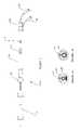
- FIG. 1depicts a general view of the entire deflectable microimplant-delivery system
- FIG. 1Ais a view through cross section A—A of the distal working length of the catheter assembly
- FIG. 1Bis a view through cross section B—B of the proximal working length of the catheter assembly
- FIG. 2Adepicts a cross section view of the distal portion of the handle assembly with the distal working length of the catheter in a substantially non-deflected mode
- FIG. 2Bdepicts a cross section view of the distal portion of the handle assembly with the distal working length of the catheter in a deflected mode
- FIG. 3shows a detailed cross section view of the proximal portion of the handle assembly
- FIG. 4is a cross section of the entire catheter assembly in a non-deflected position showing the relative position of the inner core member and the catheter;
- FIG. 5is a cross section of the entire catheter assembly with the distal end in a deflected position indicating the relative position of the inner core member, with respect to the distal end of the catheter, remaining substantially unchanged;
- FIG. 6is a cross section of the entire catheter assembly with the catheter shaft in a deflected position and the inner core member in an extended position.
- the present inventionrelates to a deflectable catheter assembly including a distal shaft section, a proximal handle subassembly and an inner core member for delivery of therapeutic agents, cellular-based materials, or a combination thereof, to diseased, injured or defective tissue.
- a deflectable catheter assemblyincluding a distal shaft section, a proximal handle subassembly and an inner core member for delivery of therapeutic agents, cellular-based materials, or a combination thereof, to diseased, injured or defective tissue.
- FIG. 1An overall view of the deflectable microimplant delivery system 10 is given in FIG. 1 .
- This catheter apparatusincludes shaft or working length (that portion of the catheter apparatus which physically enters the patient) 20 and handle assembly 30 .
- FIG. 1also shows the deflection knob 32 , inner core advancement control member 42 , insertion depth gauge 54 , inner core depth control knob 52 , injection port 56 and sheath port 58 , all of which will be explained in more detail below with reference to FIGS. 2A , 2 B and 3 .
- FIG. 1Ais a cross section through the distal portion of working length 20 .
- This distal working lengthadmits to an outer shaft with a multi-lumen section comprising a first inner lumen within which is the inner core member or needle assembly 22 , a second lumen containing pull wire 24 , which is fixed at its distal end to the distal portion of shaft 20 , and a third lumen housing ribbon 26 .
- the pull wire 24is tensioned, by distal advancement of the deflection knob 32 , the distal end of the shaft 20 is deflected (as better seen in FIG. 2B ).
- ribbon 26exists only in the distal portion of the shaft 20 as can be seen in a comparison between FIG. 1A and FIG. 1B (which is a cross section through the proximal portion of working length 20 ).
- the ribbon 26assists in returning the distal tip of the catheter shaft to the substantially non-deflected position when deflection knob 32 is retracted proximally.
- ribbon 26assists in the torquing and tracking of the distal portion of the working length 20 and in deflection thereof.
- the ribbon 26also enhances pushability of the delivery system while maintaining integrity of the distal portion of the working length 20 .
- Ribbon 26can me made from any suitable material such as stainless steel, cobalt-chromium alloys, polymers and the like.
- FIGS. 2A and 2Bindicate the working length 20 of the catheter system along with a longitudinal cross section through the distal portion of the handle assembly 30 .
- Pull wire 24traverses a groove in pulley member 36 and is fixed at its proximal end to deflection rod 34 .
- Pulley 36is fixed to pulley base 35 .
- pulley base 35is not fixed to the distal handle housing. But the pulley base 35 may be secured with respect to the handle assembly with, for example, mechanical fasteners, such as a set screw, or adhesives or the like.
- the deflection knob 32When the deflection knob 32 is advanced distally, as shown in FIG. 2B , it places the pull wire 24 in tension, thereby causing the distal end of the shaft 20 to deflect.
- the pulley 36is employed to substantially maintain the relative position of the inner core member 22 with respect to the distal end of shaft 20 when the shaft 20 is deflected (as better shown in FIG. 5 ). And pulley 36 also lessens the risk of the inner core member 22 from advancing out of, or retracting in from, the distal end of shaft 20 when the shaft 20 is manipulated during delivery to the site to be treated.
- the distal tip of the inner core member 22can be caused to extend beyond, or retreat proximally, from the distal end of the shaft 20 unintentionally. And therefore, the relative position of the inner core member 22 with respect to the distal end of shaft 20 when the shaft 20 is deflected can vary leading to inaccurate insertion depths of the inner core member 22 , without such advantage.
- FIG. 3shows the details of the proximal end of the handle assembly 30 .
- This portion of the handle assembly 30includes seal housing 38 surrounding the inner core member 22 , slide member 40 , insertion knob or inner core member advancement control 42 , return spring 46 , internal flange 48 , depth stop member 50 , depth knob or inner core insertion depth control 52 , depth indicator or insertion depth gauge 54 , injection port 56 , and sheath port 58 .
- Insertion knob 42is fixed to and slides with slide member 40 .
- Slide member 40can comprise a one piece unit or include a second proximal element 44 (as shown), for ease of manufacturing, which is fixed to the slide member 40 by, for example, mechanical fasteners, adhesives and the like.
- Insertion depth gauge 54which is fixed to depth stop member 50 , gives a visual indication of the maximum depth of insertion of inner core member 22 .
- Inner core insertion depth control 52sets the position of the insertion depth gauge 54 .
- depth knob 52which threadingly engages depth stop 50 , axially translates depth stop member 50 and depth indicator 54 , therefore limiting maximum distal axial movement of inner core member 22 by limiting the maximum distal axial travel, in the embodiment shown, of second proximal slide element 44 , which is fixed to the slide member 40 , which is in turn fixed to insertion knob 42 .
- Injection port 56is used to inject various therapeutic treatments such as myogenic cells, bone marrow derived stem cells, endothelial cells, cardiomyocytes, angiogenic growth factors, drugs or any combination thereof.
- Sheath port 58is used to flush the lumen containing the inner core member 22 .
- the inner core insertion depth control 52sets the maximum distance that the inner core member 22 , slide member 40 and insertion knob 42 can travel. That maximum distance is indicated on the depth gauge 54 .
- Inner core advancement control 42is advanced manually against the bias of return spring 46 .
- Return spring 46has its distal end seated in abutting fashion to flange 48 formed on the inside of the handle assembly 30 .
- the return spring 46acts to retract the inner core member 22 when pressure is released on the insertion knob 42 .
- therapeutic agentscan then be delivered through the injection port 56 .
- FIG. 4depicts a cut away view of the entire microimplant delivery system in the non-deflected mode with the inner core member in the retracted position.
- FIG. 5is similar to FIG. 4 except that the catheter apparatus is indicated in a deflected mode with the inner core member remaining in the retracted position.
- FIG. 6is a view similar to FIG. 5 except that the inner core member is now shown in an extended position.
- the present inventionis embodied in a deflectable microimplant delivery system 10 for treating regions of the myocardium damaged by myocardial infarction.
- the systemis introduced into the patient's vascular system through a major vessel in a manner and using techniques well known to those of ordinary skill in this art.
- the systemis introduced into the femoral artery, advanced up through the descending aorta, over the aortic arch, down the ascending aorta, through the aortic valve and into the left ventricle.
- the location of the distal tip of the catheter shaft 20 within the left ventriclecan be verified.
- the catheter shaft 20is deflected, by deflection knob 32 , as depicted in FIG. 5 , such that the distal tip is disposed against a site on the endocardial surface of the left ventricle.
- the maximum depth of insertion of the inner core member into the myocardiumis set via rotation of the insertion depth control knob 52 .
- Inner core advancement control member 42is then manipulated to move the inner core member 22 towards an extended position, as shown in FIG. 6 , piercing through the endocardium and into the myocardium.
- the inner core member 22is provided with a beveled or skived tip to facilitate piercing of the endocardium through and into the myocardium.
- the desired therapeutic solutionis then injected through the injection port and the inner core member into the myocardium. A number of injections may be performed at or around the infarct zone or the catheter can be repositioned to treat other areas of the left ventricle.
- the deflectable microimplant delivery system described abovecan be used to inject therapeutic agents and cellular-based materials into any other chamber of the heart, such as by venous approach, for example femoral vein or internal jugular vein, or into almost any body tissue requiring treatment or repair. Including, for example, the kidneys, liver, brain, gastrointestinal tract, esophagus, and vascular system.
- a deflectable catheter assembly with a working length section and a handle subassembly for delivery of one or more therapeutic agents and/or cellular-based therapieshas been disclosed.
- the present inventionhas been described in accordance with the embodiments shown, one of ordinary skill in the art will readily recognize that there could be variations to the embodiments and those variations would be within the spirit and scope of the present invention.
- the inner core member and/or the distal portion of the catheter shaftcould be designed to cause the inner core member to deflect at an angle oblique to the distal tip of the catheter shaft. This could allow for a longer track for the implanted media, with more therapeutic media being implanted with less risk of leakage of the therapeutic media. Moreover, this modification could also reduce the risk or likelihood of the inner core member piercing or passing completely through the organ or tissue to be treated.
- inner core member 22can be drawn from a single piece of hypotubing or be formed as a multi-piece assembly. More specifically, needle assembly 22 can comprise a proximal hypotube portion, a distal skived hypotube section, with an intermediate polyimide tubing bonded at its proximal end to the proximal hypotube portin and at its distal end to the skived hypotube section. The latter described multi-section needle assembly enhances the overall deliverablity of the deflectable delivery system.
- microimplant delivery systemcan be used to introduce a host of cellular matter to the treatment site, which can include myogenic cells, vascular endothelial growth factors, fibroblast growth factors, bone marrow derived stem cells, endothelial cells, cardiomyocytes or any combination of these or other biological or therapeutic agents.
- the catheter apparatuscan be used as a tool for transmyocardial revascularization.
- the catheter apparatusfor example, could be used to form channels into the myocardium with or without the deposition of angiogenic enhancing substances such as vascular endothelial growth factors and fibroblast growth factors.
Landscapes
- Health & Medical Sciences (AREA)
- Life Sciences & Earth Sciences (AREA)
- Biophysics (AREA)
- Pulmonology (AREA)
- Engineering & Computer Science (AREA)
- Anesthesiology (AREA)
- Biomedical Technology (AREA)
- Heart & Thoracic Surgery (AREA)
- Hematology (AREA)
- Animal Behavior & Ethology (AREA)
- General Health & Medical Sciences (AREA)
- Public Health (AREA)
- Veterinary Medicine (AREA)
- Media Introduction/Drainage Providing Device (AREA)
Abstract
Description
Claims (34)
Priority Applications (2)
| Application Number | Priority Date | Filing Date | Title |
|---|---|---|---|
| US10/152,110US7033345B2 (en) | 2002-05-21 | 2002-05-21 | Deflectable microimplant delivery system |
| US11/271,076US8002739B2 (en) | 2002-05-21 | 2005-11-10 | Deflectable microimplant delivery system |
Applications Claiming Priority (1)
| Application Number | Priority Date | Filing Date | Title |
|---|---|---|---|
| US10/152,110US7033345B2 (en) | 2002-05-21 | 2002-05-21 | Deflectable microimplant delivery system |
Related Child Applications (1)
| Application Number | Title | Priority Date | Filing Date |
|---|---|---|---|
| US11/271,076ContinuationUS8002739B2 (en) | 2002-05-21 | 2005-11-10 | Deflectable microimplant delivery system |
Publications (2)
| Publication Number | Publication Date |
|---|---|
| US20040039338A1 US20040039338A1 (en) | 2004-02-26 |
| US7033345B2true US7033345B2 (en) | 2006-04-25 |
Family
ID=31886338
Family Applications (2)
| Application Number | Title | Priority Date | Filing Date |
|---|---|---|---|
| US10/152,110Expired - Fee RelatedUS7033345B2 (en) | 2002-05-21 | 2002-05-21 | Deflectable microimplant delivery system |
| US11/271,076Expired - Fee RelatedUS8002739B2 (en) | 2002-05-21 | 2005-11-10 | Deflectable microimplant delivery system |
Family Applications After (1)
| Application Number | Title | Priority Date | Filing Date |
|---|---|---|---|
| US11/271,076Expired - Fee RelatedUS8002739B2 (en) | 2002-05-21 | 2005-11-10 | Deflectable microimplant delivery system |
Country Status (1)
| Country | Link |
|---|---|
| US (2) | US7033345B2 (en) |
Cited By (10)
| Publication number | Priority date | Publication date | Assignee | Title |
|---|---|---|---|---|
| US20070156116A1 (en)* | 2005-12-30 | 2007-07-05 | Gonzalez Pablo A | Dual-lever bi-directional handle |
| DE102009037827A1 (en) | 2009-08-10 | 2011-02-17 | Epflex Feinwerktechnik Gmbh | Medical catheter instrument |
| WO2011041478A1 (en) | 2009-10-02 | 2011-04-07 | Baxter International Inc. | Hematopoietic stem cells for use in the treatment of a kidney injury |
| US20130123620A1 (en)* | 2011-11-16 | 2013-05-16 | Cook Medical Technologies Llc | Tip deflecting puncture needle |
| US8486024B2 (en) | 2011-04-27 | 2013-07-16 | Covidien Lp | Safety IV catheter assemblies |
| WO2013126590A2 (en) | 2012-02-21 | 2013-08-29 | Baxter International Inc. | Pharmaceutical composition comprising cd34+ cells |
| US8628497B2 (en) | 2011-09-26 | 2014-01-14 | Covidien Lp | Safety catheter |
| US8715250B2 (en) | 2011-09-26 | 2014-05-06 | Covidien Lp | Safety catheter and needle assembly |
| US8834422B2 (en) | 2011-10-14 | 2014-09-16 | Covidien Lp | Vascular access assembly and safety device |
| US8939938B2 (en) | 2006-10-12 | 2015-01-27 | Covidien Lp | Needle tip protector |
Families Citing this family (27)
| Publication number | Priority date | Publication date | Assignee | Title |
|---|---|---|---|---|
| US7192415B2 (en)* | 2002-03-22 | 2007-03-20 | Scimed Life Systems, Inc. | Drainage catheter with visual indicator and/or lock system |
| US7328064B2 (en) | 2002-07-04 | 2008-02-05 | Inovio As | Electroporation device and injection apparatus |
| US8636694B2 (en)* | 2004-06-14 | 2014-01-28 | Medtronic, Inc. | Modular medical injection system |
| US8114110B2 (en)* | 2004-09-22 | 2012-02-14 | St. Jude Medical, Atrial Fibrillation Division, Inc. | Transseptal puncture needle and needle assemblies |
| US9326756B2 (en)* | 2006-05-17 | 2016-05-03 | St. Jude Medical, Atrial Fibrillation Division, Inc. | Transseptal catheterization assembly and methods |
| US8430888B2 (en)* | 2005-02-22 | 2013-04-30 | Boston Scientific Neuromodulation Corporation | Minimally invasive methods for locating an optimal location for deep brain stimulation |
| US7369899B2 (en)* | 2005-02-22 | 2008-05-06 | Boston Scientific Neuromodulation Corporation | Minimally invasive systems for locating an optimal location for deep brain stimulation |
| CA2600277A1 (en)* | 2005-03-04 | 2006-09-08 | Cathrx Ltd | A catheter handle and a catheter assembly including such a handle |
| EP1907041B1 (en)* | 2005-07-11 | 2019-02-20 | Catheter Precision, Inc. | Remotely controlled catheter insertion system |
| US8038595B2 (en)* | 2006-01-25 | 2011-10-18 | Beth Israel Deaconess Medical Center | Devices and methods for tissue transplant and regeneration |
| US20080287909A1 (en)* | 2007-05-17 | 2008-11-20 | Viswanathan Raju R | Method and apparatus for intra-chamber needle injection treatment |
| US8480653B2 (en) | 2007-05-23 | 2013-07-09 | Biosense Webster, Inc. | Magnetically guided catheter with concentric needle port |
| US8192399B2 (en)* | 2007-05-23 | 2012-06-05 | Biosense Webster, Inc. | Extension control handle with adjustable locking mechanism |
| US8603046B2 (en)* | 2007-05-23 | 2013-12-10 | Biosense Webster, Inc. | Automated injection catheter device and system |
| AU2008202483B2 (en)* | 2007-06-15 | 2011-07-14 | Cathrx Ltd | A deflectable stylet |
| US8808345B2 (en) | 2008-12-31 | 2014-08-19 | Medtronic Ardian Luxembourg S.A.R.L. | Handle assemblies for intravascular treatment devices and associated systems and methods |
| US8298187B2 (en) | 2009-07-07 | 2012-10-30 | Cook Medical Technologies Llc | Fluid injection device |
| EP2633876B1 (en) | 2012-03-02 | 2014-09-24 | Cook Medical Technologies LLC | Dilation cap for endoluminal device |
| WO2019094834A1 (en) | 2017-11-09 | 2019-05-16 | Inceptus Medical LLC | Interlocking loop coupling/decoupling system for deploying vascular implant devices |
| CN110638488B (en)* | 2018-06-26 | 2025-08-15 | 杭州唯强医疗科技有限公司 | Implant pushing device with reliable connection and implant conveying system |
| CN110638490B (en)* | 2018-06-26 | 2025-08-15 | 杭州唯强医疗科技有限公司 | Lockable implant pushing device and implant delivery system |
| CN111803170A (en)* | 2019-04-12 | 2020-10-23 | 杭州诺茂医疗科技有限公司 | Interventional medical device pusher and interventional medical device delivery system |
| EP4167892A4 (en) | 2020-06-19 | 2024-10-30 | Remedy Robotics, Inc. | SYSTEMS AND METHODS FOR GUIDING INTRALUMINAL DEVICES WITHIN THE VASCULAR SYSTEM |
| KR102372360B1 (en)* | 2020-06-24 | 2022-03-08 | 권승열 | Multi catheter |
| US11707332B2 (en) | 2021-07-01 | 2023-07-25 | Remedy Robotics, Inc. | Image space control for endovascular tools |
| EP4364163A1 (en) | 2021-07-01 | 2024-05-08 | Remedy Robotics, Inc. | Vision-based position and orientation determination for endovascular tools |
| US12121307B2 (en) | 2021-07-01 | 2024-10-22 | Remedy Robotics, Inc. | Vision-based position and orientation determination for endovascular tools |
Citations (53)
| Publication number | Priority date | Publication date | Assignee | Title |
|---|---|---|---|---|
| US3780733A (en) | 1972-07-24 | 1973-12-25 | Manzor M Martinez | Catheter |
| US4578057A (en) | 1984-08-31 | 1986-03-25 | Cordis Corporation | Ventricular right angle connector and system |
| US4898577A (en) | 1988-09-28 | 1990-02-06 | Advanced Cardiovascular Systems, Inc. | Guiding cathether with controllable distal tip |
| US5092848A (en) | 1988-10-13 | 1992-03-03 | Deciutiis Vincent L | Intravenous catheter with built-in cutting tip and method for making the same |
| WO1992010142A1 (en) | 1990-12-10 | 1992-06-25 | Howmedica Inc. | A device and method for interstitial laser energy delivery |
| US5281218A (en) | 1992-06-05 | 1994-01-25 | Cardiac Pathways Corporation | Catheter having needle electrode for radiofrequency ablation |
| US5336252A (en) | 1992-06-22 | 1994-08-09 | Cohen Donald M | System and method for implanting cardiac electrical leads |
| US5354279A (en) | 1992-10-21 | 1994-10-11 | Bavaria Medizin Technologie Gmbh | Plural needle injection catheter |
| US5380292A (en) | 1993-12-22 | 1995-01-10 | Wilson-Cook Medical, Inc. | Gastrointestinal needle mechanism |
| US5437632A (en) | 1993-06-02 | 1995-08-01 | Target Therapeutics, Inc. | Variable stiffness balloon catheter |
| US5591159A (en) | 1994-11-09 | 1997-01-07 | Taheri; Syde A. | Transcavitary myocardial perfusion apparatus |
| US5606974A (en) | 1995-05-02 | 1997-03-04 | Heart Rhythm Technologies, Inc. | Catheter having ultrasonic device |
| US5658263A (en) | 1995-05-18 | 1997-08-19 | Cordis Corporation | Multisegmented guiding catheter for use in medical catheter systems |
| US5785689A (en) | 1996-07-18 | 1998-07-28 | Act Medical, Inc. | Endoscopic catheter sheath position control |
| US5797870A (en) | 1995-06-07 | 1998-08-25 | Indiana University Foundation | Pericardial delivery of therapeutic and diagnostic agents |
| EP0861632A1 (en) | 1997-01-30 | 1998-09-02 | Nissho Corporation | Catheter assembly for intracardiac suture |
| US5814028A (en) | 1993-11-03 | 1998-09-29 | Daig Corporation | Curved guiding introducers for cardiac access |
| US5876373A (en) | 1997-04-04 | 1999-03-02 | Eclipse Surgical Technologies, Inc. | Steerable catheter |
| US5916214A (en) | 1995-05-01 | 1999-06-29 | Medtronic Cardiorhythm | Dual curve ablation catheter |
| US5921982A (en) | 1993-07-30 | 1999-07-13 | Lesh; Michael D. | Systems and methods for ablating body tissue |
| EP0938871A2 (en) | 1998-02-27 | 1999-09-01 | ECLIPSE SURGICAL TECHNOLOGIES, Inc. | Surgical apparatus |
| US5964754A (en) | 1996-05-24 | 1999-10-12 | Sulzer Osypka Gmbh | Device for perforating the heart wall |
| US5980545A (en) | 1996-05-13 | 1999-11-09 | United States Surgical Corporation | Coring device and method |
| US5989278A (en) | 1996-09-13 | 1999-11-23 | Eclipse Surgical Technologies, Inc. | Method and apparatus for mechanical transmyocardial revascularization of the heart |
| US6036677A (en) | 1997-03-07 | 2000-03-14 | Cardiogenesis Corporation | Catheter with flexible intermediate section |
| US6045530A (en) | 1998-10-14 | 2000-04-04 | Heyer-Schulte Neurocare Inc. | Adjustable angle catheter |
| US6045565A (en) | 1997-11-04 | 2000-04-04 | Scimed Life Systems, Inc. | Percutaneous myocardial revascularization growth factor mediums and method |
| US6066126A (en) | 1997-12-18 | 2000-05-23 | Medtronic, Inc. | Precurved, dual curve cardiac introducer sheath |
| US6106520A (en) | 1997-09-30 | 2000-08-22 | Hearten Medical, Inc. | Endocardial device for producing reversible damage to heart tissue |
| WO2000071196A1 (en) | 1999-05-21 | 2000-11-30 | Micro Therapeutics, Inc. | Interface needle and method for creating a blunt interface between delivered liquids |
| US6165164A (en) | 1999-03-29 | 2000-12-26 | Cordis Corporation | Catheter for injecting therapeutic and diagnostic agents |
| US6165183A (en) | 1998-07-15 | 2000-12-26 | St. Jude Medical, Inc. | Mitral and tricuspid valve repair |
| US6179809B1 (en) | 1997-09-24 | 2001-01-30 | Eclipse Surgical Technologies, Inc. | Drug delivery catheter with tip alignment |
| US6183444B1 (en) | 1998-05-16 | 2001-02-06 | Microheart, Inc. | Drug delivery module |
| US6206893B1 (en) | 1993-11-08 | 2001-03-27 | Perclose, Inc. | Device and method for suturing of internal puncture sites |
| US6224584B1 (en) | 1997-01-14 | 2001-05-01 | Eclipse Surgical Technologies, Inc. | Therapeutic and diagnostic agent delivery |
| US6241710B1 (en) | 1999-12-20 | 2001-06-05 | Tricardia Llc | Hypodermic needle with weeping tip and method of use |
| US6251104B1 (en) | 1995-05-10 | 2001-06-26 | Eclipse Surgical Technologies, Inc. | Guiding catheter system for ablating heart tissue |
| WO2001049357A2 (en) | 1999-12-30 | 2001-07-12 | Advanced Cardiovascular Systems, Inc. | A substance delivery apparatus and a method of delivering a therapeutic substance into the wall of an anatomical passageway |
| US6269819B1 (en) | 1997-06-27 | 2001-08-07 | The Trustees Of Columbia University In The City Of New York | Method and apparatus for circulatory valve repair |
| US6270496B1 (en) | 1998-05-05 | 2001-08-07 | Cardiac Pacemakers, Inc. | Steerable catheter with preformed distal shape and method for use |
| US6283947B1 (en) | 1999-07-13 | 2001-09-04 | Advanced Cardiovascular Systems, Inc. | Local drug delivery injection catheter |
| US6309370B1 (en) | 1998-02-05 | 2001-10-30 | Biosense, Inc. | Intracardiac drug delivery |
| US6312447B1 (en) | 1999-10-13 | 2001-11-06 | The General Hospital Corporation | Devices and methods for percutaneous mitral valve repair |
| US6322548B1 (en) | 1995-05-10 | 2001-11-27 | Eclipse Surgical Technologies | Delivery catheter system for heart chamber |
| US6358258B1 (en) | 1999-09-14 | 2002-03-19 | Abbott Laboratories | Device and method for performing end-to-side anastomosis |
| US20020035361A1 (en) | 1999-06-25 | 2002-03-21 | Houser Russell A. | Apparatus and methods for treating tissue |
| US6511471B2 (en)* | 2000-12-22 | 2003-01-28 | Biocardia, Inc. | Drug delivery catheters that attach to tissue and methods for their use |
| US6554794B1 (en)* | 1997-09-24 | 2003-04-29 | Richard L. Mueller | Non-deforming deflectable multi-lumen catheter |
| US6599267B1 (en) | 2000-12-22 | 2003-07-29 | Advanced Cardiovascular Systems, Inc. | Transluminal injection device for intravascular drug delivery |
| US6623473B1 (en)* | 1998-06-04 | 2003-09-23 | Biosense Webster, Inc. | Injection catheter with multi-directional delivery injection needle |
| US20030181869A1 (en)* | 2002-03-20 | 2003-09-25 | Becton, Dickinson And Company | Needle assembly |
| US20030220619A1 (en)* | 1997-03-26 | 2003-11-27 | Polidoro John M. | Parenteral fluid transfer apparatus |
Family Cites Families (4)
| Publication number | Priority date | Publication date | Assignee | Title |
|---|---|---|---|---|
| US5944690A (en)* | 1997-03-17 | 1999-08-31 | C.R. Bard, Inc. | Slidable control mechanism for steerable catheter |
| US6358358B1 (en)* | 1999-09-07 | 2002-03-19 | Thomas Bilisoly | Method and apparatus for producing signs with a weeding and laminating system |
| IT1313625B1 (en)* | 1999-09-22 | 2002-09-09 | Boehringer Ingelheim Italia | BENZIMIDAZOLONIC DERIVATIVES WITH MIXED AFFINITY FOR DYEROTONIN AND DOPAMIN RECEPTORS. |
| US6293947B1 (en)* | 2000-01-28 | 2001-09-25 | Daniel Buchbinder | Distraction osteogenesis device and method |
- 2002
- 2002-05-21USUS10/152,110patent/US7033345B2/ennot_activeExpired - Fee Related
- 2005
- 2005-11-10USUS11/271,076patent/US8002739B2/ennot_activeExpired - Fee Related
Patent Citations (57)
| Publication number | Priority date | Publication date | Assignee | Title |
|---|---|---|---|---|
| US3780733A (en) | 1972-07-24 | 1973-12-25 | Manzor M Martinez | Catheter |
| US4578057A (en) | 1984-08-31 | 1986-03-25 | Cordis Corporation | Ventricular right angle connector and system |
| US4898577A (en) | 1988-09-28 | 1990-02-06 | Advanced Cardiovascular Systems, Inc. | Guiding cathether with controllable distal tip |
| US5092848A (en) | 1988-10-13 | 1992-03-03 | Deciutiis Vincent L | Intravenous catheter with built-in cutting tip and method for making the same |
| WO1992010142A1 (en) | 1990-12-10 | 1992-06-25 | Howmedica Inc. | A device and method for interstitial laser energy delivery |
| US5281218A (en) | 1992-06-05 | 1994-01-25 | Cardiac Pathways Corporation | Catheter having needle electrode for radiofrequency ablation |
| US5336252A (en) | 1992-06-22 | 1994-08-09 | Cohen Donald M | System and method for implanting cardiac electrical leads |
| US5354279A (en) | 1992-10-21 | 1994-10-11 | Bavaria Medizin Technologie Gmbh | Plural needle injection catheter |
| US5437632A (en) | 1993-06-02 | 1995-08-01 | Target Therapeutics, Inc. | Variable stiffness balloon catheter |
| US5921982A (en) | 1993-07-30 | 1999-07-13 | Lesh; Michael D. | Systems and methods for ablating body tissue |
| US5814028A (en) | 1993-11-03 | 1998-09-29 | Daig Corporation | Curved guiding introducers for cardiac access |
| US6206893B1 (en) | 1993-11-08 | 2001-03-27 | Perclose, Inc. | Device and method for suturing of internal puncture sites |
| US5380292A (en) | 1993-12-22 | 1995-01-10 | Wilson-Cook Medical, Inc. | Gastrointestinal needle mechanism |
| US5591159A (en) | 1994-11-09 | 1997-01-07 | Taheri; Syde A. | Transcavitary myocardial perfusion apparatus |
| US5916214A (en) | 1995-05-01 | 1999-06-29 | Medtronic Cardiorhythm | Dual curve ablation catheter |
| US5606974A (en) | 1995-05-02 | 1997-03-04 | Heart Rhythm Technologies, Inc. | Catheter having ultrasonic device |
| US6251104B1 (en) | 1995-05-10 | 2001-06-26 | Eclipse Surgical Technologies, Inc. | Guiding catheter system for ablating heart tissue |
| US6322548B1 (en) | 1995-05-10 | 2001-11-27 | Eclipse Surgical Technologies | Delivery catheter system for heart chamber |
| US5658263A (en) | 1995-05-18 | 1997-08-19 | Cordis Corporation | Multisegmented guiding catheter for use in medical catheter systems |
| US5797870A (en) | 1995-06-07 | 1998-08-25 | Indiana University Foundation | Pericardial delivery of therapeutic and diagnostic agents |
| US5980545A (en) | 1996-05-13 | 1999-11-09 | United States Surgical Corporation | Coring device and method |
| US5964754A (en) | 1996-05-24 | 1999-10-12 | Sulzer Osypka Gmbh | Device for perforating the heart wall |
| US5785689A (en) | 1996-07-18 | 1998-07-28 | Act Medical, Inc. | Endoscopic catheter sheath position control |
| US5989278A (en) | 1996-09-13 | 1999-11-23 | Eclipse Surgical Technologies, Inc. | Method and apparatus for mechanical transmyocardial revascularization of the heart |
| US6224584B1 (en) | 1997-01-14 | 2001-05-01 | Eclipse Surgical Technologies, Inc. | Therapeutic and diagnostic agent delivery |
| EP0861632A1 (en) | 1997-01-30 | 1998-09-02 | Nissho Corporation | Catheter assembly for intracardiac suture |
| US6036677A (en) | 1997-03-07 | 2000-03-14 | Cardiogenesis Corporation | Catheter with flexible intermediate section |
| US6093177A (en) | 1997-03-07 | 2000-07-25 | Cardiogenesis Corporation | Catheter with flexible intermediate section |
| US20030220619A1 (en)* | 1997-03-26 | 2003-11-27 | Polidoro John M. | Parenteral fluid transfer apparatus |
| US5876373A (en) | 1997-04-04 | 1999-03-02 | Eclipse Surgical Technologies, Inc. | Steerable catheter |
| US6126654A (en) | 1997-04-04 | 2000-10-03 | Eclipse Surgical Technologies, Inc. | Method of forming revascularization channels in myocardium using a steerable catheter |
| US6269819B1 (en) | 1997-06-27 | 2001-08-07 | The Trustees Of Columbia University In The City Of New York | Method and apparatus for circulatory valve repair |
| US6554794B1 (en)* | 1997-09-24 | 2003-04-29 | Richard L. Mueller | Non-deforming deflectable multi-lumen catheter |
| US6179809B1 (en) | 1997-09-24 | 2001-01-30 | Eclipse Surgical Technologies, Inc. | Drug delivery catheter with tip alignment |
| US6106520A (en) | 1997-09-30 | 2000-08-22 | Hearten Medical, Inc. | Endocardial device for producing reversible damage to heart tissue |
| US6045565A (en) | 1997-11-04 | 2000-04-04 | Scimed Life Systems, Inc. | Percutaneous myocardial revascularization growth factor mediums and method |
| US6066126A (en) | 1997-12-18 | 2000-05-23 | Medtronic, Inc. | Precurved, dual curve cardiac introducer sheath |
| US6309370B1 (en) | 1998-02-05 | 2001-10-30 | Biosense, Inc. | Intracardiac drug delivery |
| EP0938871A2 (en) | 1998-02-27 | 1999-09-01 | ECLIPSE SURGICAL TECHNOLOGIES, Inc. | Surgical apparatus |
| US6270496B1 (en) | 1998-05-05 | 2001-08-07 | Cardiac Pacemakers, Inc. | Steerable catheter with preformed distal shape and method for use |
| US6183444B1 (en) | 1998-05-16 | 2001-02-06 | Microheart, Inc. | Drug delivery module |
| US6623473B1 (en)* | 1998-06-04 | 2003-09-23 | Biosense Webster, Inc. | Injection catheter with multi-directional delivery injection needle |
| US6165183A (en) | 1998-07-15 | 2000-12-26 | St. Jude Medical, Inc. | Mitral and tricuspid valve repair |
| US6045530A (en) | 1998-10-14 | 2000-04-04 | Heyer-Schulte Neurocare Inc. | Adjustable angle catheter |
| US6165164A (en) | 1999-03-29 | 2000-12-26 | Cordis Corporation | Catheter for injecting therapeutic and diagnostic agents |
| WO2000071196A1 (en) | 1999-05-21 | 2000-11-30 | Micro Therapeutics, Inc. | Interface needle and method for creating a blunt interface between delivered liquids |
| US20020035361A1 (en) | 1999-06-25 | 2002-03-21 | Houser Russell A. | Apparatus and methods for treating tissue |
| US6283947B1 (en) | 1999-07-13 | 2001-09-04 | Advanced Cardiovascular Systems, Inc. | Local drug delivery injection catheter |
| US6358258B1 (en) | 1999-09-14 | 2002-03-19 | Abbott Laboratories | Device and method for performing end-to-side anastomosis |
| US6312447B1 (en) | 1999-10-13 | 2001-11-06 | The General Hospital Corporation | Devices and methods for percutaneous mitral valve repair |
| WO2001045548A2 (en) | 1999-12-20 | 2001-06-28 | Tricardia, L.L.C. | Surgical needle with weeping tip and method of use |
| US20010023349A1 (en) | 1999-12-20 | 2001-09-20 | Tricardia, Llc | Hypodermic needle with weeping tip and method of use |
| US6241710B1 (en) | 1999-12-20 | 2001-06-05 | Tricardia Llc | Hypodermic needle with weeping tip and method of use |
| WO2001049357A2 (en) | 1999-12-30 | 2001-07-12 | Advanced Cardiovascular Systems, Inc. | A substance delivery apparatus and a method of delivering a therapeutic substance into the wall of an anatomical passageway |
| US6511471B2 (en)* | 2000-12-22 | 2003-01-28 | Biocardia, Inc. | Drug delivery catheters that attach to tissue and methods for their use |
| US6599267B1 (en) | 2000-12-22 | 2003-07-29 | Advanced Cardiovascular Systems, Inc. | Transluminal injection device for intravascular drug delivery |
| US20030181869A1 (en)* | 2002-03-20 | 2003-09-25 | Becton, Dickinson And Company | Needle assembly |
Cited By (18)
| Publication number | Priority date | Publication date | Assignee | Title |
|---|---|---|---|---|
| US11511078B2 (en) | 2005-12-30 | 2022-11-29 | Biosense Webster, Inc. | Dual-lever bi-directional handle |
| US10569053B2 (en) | 2005-12-30 | 2020-02-25 | Biosense Webster, Inc. | Dual-lever bi-directional handle |
| US9833595B2 (en)* | 2005-12-30 | 2017-12-05 | Biosense Webster, Inc. | Dual-lever bi-directional handle |
| US20070156116A1 (en)* | 2005-12-30 | 2007-07-05 | Gonzalez Pablo A | Dual-lever bi-directional handle |
| US8939938B2 (en) | 2006-10-12 | 2015-01-27 | Covidien Lp | Needle tip protector |
| DE102009037827A1 (en) | 2009-08-10 | 2011-02-17 | Epflex Feinwerktechnik Gmbh | Medical catheter instrument |
| US9174022B2 (en) | 2009-08-10 | 2015-11-03 | Epflex Feinwerktechnik Gmbh | Medical catheter instrument |
| WO2011041478A1 (en) | 2009-10-02 | 2011-04-07 | Baxter International Inc. | Hematopoietic stem cells for use in the treatment of a kidney injury |
| US20110091427A1 (en)* | 2009-10-02 | 2011-04-21 | Baxter International Inc. | Methods for treating a kidney injury |
| US8926563B2 (en) | 2011-04-27 | 2015-01-06 | Covidien Lp | Safety IV catheter assemblies |
| US8486024B2 (en) | 2011-04-27 | 2013-07-16 | Covidien Lp | Safety IV catheter assemblies |
| US8715250B2 (en) | 2011-09-26 | 2014-05-06 | Covidien Lp | Safety catheter and needle assembly |
| US9375552B2 (en) | 2011-09-26 | 2016-06-28 | Covidien Lp | Safety needle assembly |
| US8628497B2 (en) | 2011-09-26 | 2014-01-14 | Covidien Lp | Safety catheter |
| US8834422B2 (en) | 2011-10-14 | 2014-09-16 | Covidien Lp | Vascular access assembly and safety device |
| US8831707B2 (en)* | 2011-11-16 | 2014-09-09 | Cook Medical Technologies Llc | Tip deflecting puncture needle |
| US20130123620A1 (en)* | 2011-11-16 | 2013-05-16 | Cook Medical Technologies Llc | Tip deflecting puncture needle |
| WO2013126590A2 (en) | 2012-02-21 | 2013-08-29 | Baxter International Inc. | Pharmaceutical composition comprising cd34+ cells |
Also Published As
| Publication number | Publication date |
|---|---|
| US20060095004A1 (en) | 2006-05-04 |
| US8002739B2 (en) | 2011-08-23 |
| US20040039338A1 (en) | 2004-02-26 |
Similar Documents
| Publication | Publication Date | Title |
|---|---|---|
| US7033345B2 (en) | Deflectable microimplant delivery system | |
| AU712738B2 (en) | Steerable catheter | |
| US6179809B1 (en) | Drug delivery catheter with tip alignment | |
| US20220031389A1 (en) | Catheter for peri-vascular fluid injection | |
| US6623473B1 (en) | Injection catheter with multi-directional delivery injection needle | |
| US7691086B2 (en) | Catheter for introduction of medications to the tissues of a heart or other organ | |
| US6322548B1 (en) | Delivery catheter system for heart chamber | |
| US6217554B1 (en) | Methods and apparatus for delivering substances into extravascular tissue | |
| US7416547B2 (en) | Injection catheter | |
| US6905476B2 (en) | Catheter with injection needle | |
| US7468057B2 (en) | Injection catheter with controllably extendable injection needle | |
| US6575931B1 (en) | Catheter with injection needle | |
| US20080045890A1 (en) | Methods and systems for ablating tissue | |
| US20030032936A1 (en) | Side-exit catheter and method for its use | |
| US20040116868A1 (en) | Intra-pericardial drug delivery device with multiple-balloons and method for angiogenesis | |
| EP1231864A2 (en) | Drug delivery catheters that attach to tissue and methods for their use | |
| WO2002047753A1 (en) | Catheter assembly for treating ischemic tissue | |
| CA2326409C (en) | Injection catheter | |
| US20050182071A1 (en) | Methods and systems for inhibiting arrhythmia | |
| US20090118673A1 (en) | Needle injection catheter | |
| AU8703298A (en) | Drug delivery catheter | |
| WO2002047750A2 (en) | Catheter assembly for treating ischemic tissue |
Legal Events
| Date | Code | Title | Description |
|---|---|---|---|
| AS | Assignment | Owner name:ADVANCED CARDIOVASCULAR SYSTEMS, INC., CALIFORNIA Free format text:ASSIGNMENT OF ASSIGNORS INTEREST;ASSIGNOR:BIOHEART, INC.;REEL/FRAME:014567/0385 Effective date:20030914 Owner name:ADVANCED CARDIOVASCULAR SYSTEMS, INC.,CALIFORNIA Free format text:ASSIGNMENT OF ASSIGNORS INTEREST;ASSIGNOR:BIOHEART, INC.;REEL/FRAME:014567/0385 Effective date:20030914 | |
| AS | Assignment | Owner name:ADVANCED CARDIOVASCULAR SYSTEMS, INC., CALIFORNIA Free format text:ASSIGNMENT OF ASSIGNORS INTEREST;ASSIGNOR:BIOHEART, INC.;REEL/FRAME:014119/0629 Effective date:20030624 Owner name:ADVANCED CARDIOVASCULAR SYSTEMS, INC.,CALIFORNIA Free format text:ASSIGNMENT OF ASSIGNORS INTEREST;ASSIGNOR:BIOHEART, INC.;REEL/FRAME:014119/0629 Effective date:20030624 | |
| FPAY | Fee payment | Year of fee payment:4 | |
| FPAY | Fee payment | Year of fee payment:8 | |
| FEPP | Fee payment procedure | Free format text:MAINTENANCE FEE REMINDER MAILED (ORIGINAL EVENT CODE: REM.) | |
| LAPS | Lapse for failure to pay maintenance fees | Free format text:PATENT EXPIRED FOR FAILURE TO PAY MAINTENANCE FEES (ORIGINAL EVENT CODE: EXP.) | |
| STCH | Information on status: patent discontinuation | Free format text:PATENT EXPIRED DUE TO NONPAYMENT OF MAINTENANCE FEES UNDER 37 CFR 1.362 | |
| FP | Lapsed due to failure to pay maintenance fee | Effective date:20180425 |