US7033317B2 - Disposable endoscope and method of making a disposable endoscope - Google Patents
Disposable endoscope and method of making a disposable endoscopeDownload PDFInfo
- Publication number
- US7033317B2 US7033317B2US10/863,874US86387404AUS7033317B2US 7033317 B2US7033317 B2US 7033317B2US 86387404 AUS86387404 AUS 86387404AUS 7033317 B2US7033317 B2US 7033317B2
- Authority
- US
- United States
- Prior art keywords
- sheath
- endoscope
- distal tip
- distal
- distal end
- Prior art date
- Legal status (The legal status is an assumption and is not a legal conclusion. Google has not performed a legal analysis and makes no representation as to the accuracy of the status listed.)
- Expired - Fee Related
Links
- 238000004519manufacturing processMethods0.000titledescription8
- 238000003384imaging methodMethods0.000claimsabstractdescription45
- 239000000463materialSubstances0.000claimsdescription13
- 238000005520cutting processMethods0.000claimsdescription8
- 238000000034methodMethods0.000claimsdescription8
- 239000004593EpoxySubstances0.000claimsdescription6
- 239000011521glassSubstances0.000claimsdescription4
- 239000010410layerSubstances0.000claimsdescription4
- 239000012790adhesive layerSubstances0.000claimsdescription3
- 230000003213activating effectEffects0.000claims2
- 239000000835fiberSubstances0.000description13
- 239000000853adhesiveSubstances0.000description9
- 230000001070adhesive effectEffects0.000description9
- 230000003287optical effectEffects0.000description3
- 238000005498polishingMethods0.000description3
- 238000000926separation methodMethods0.000description2
- 238000004026adhesive bondingMethods0.000description1
- 239000006117anti-reflective coatingSubstances0.000description1
- 239000011324beadSubstances0.000description1
- 238000005452bendingMethods0.000description1
- 230000005540biological transmissionEffects0.000description1
- 150000001875compoundsChemical class0.000description1
- 230000000694effectsEffects0.000description1
- 229920006332epoxy adhesivePolymers0.000description1
- 239000012530fluidSubstances0.000description1
- 238000005286illuminationMethods0.000description1
- 238000001746injection mouldingMethods0.000description1
- 208000014674injuryDiseases0.000description1
- 230000002262irrigationEffects0.000description1
- 238000003973irrigationMethods0.000description1
- 239000002184metalSubstances0.000description1
- 210000001747pupilAnatomy0.000description1
- 230000000717retained effectEffects0.000description1
- 239000013589supplementSubstances0.000description1
- 230000001225therapeutic effectEffects0.000description1
- 230000008733traumaEffects0.000description1
- 238000011144upstream manufacturingMethods0.000description1
- 238000003466weldingMethods0.000description1
Images


Classifications
- A—HUMAN NECESSITIES
- A61—MEDICAL OR VETERINARY SCIENCE; HYGIENE
- A61B—DIAGNOSIS; SURGERY; IDENTIFICATION
- A61B1/00—Instruments for performing medical examinations of the interior of cavities or tubes of the body by visual or photographical inspection, e.g. endoscopes; Illuminating arrangements therefor
- A61B1/00064—Constructional details of the endoscope body
- A61B1/00071—Insertion part of the endoscope body
- A61B1/0008—Insertion part of the endoscope body characterised by distal tip features
- A61B1/00096—Optical elements
- A—HUMAN NECESSITIES
- A61—MEDICAL OR VETERINARY SCIENCE; HYGIENE
- A61B—DIAGNOSIS; SURGERY; IDENTIFICATION
- A61B1/00—Instruments for performing medical examinations of the interior of cavities or tubes of the body by visual or photographical inspection, e.g. endoscopes; Illuminating arrangements therefor
- A61B1/00064—Constructional details of the endoscope body
- A61B1/00071—Insertion part of the endoscope body
- A61B1/0008—Insertion part of the endoscope body characterised by distal tip features
- A61B1/00101—Insertion part of the endoscope body characterised by distal tip features the distal tip features being detachable
- A—HUMAN NECESSITIES
- A61—MEDICAL OR VETERINARY SCIENCE; HYGIENE
- A61B—DIAGNOSIS; SURGERY; IDENTIFICATION
- A61B1/00—Instruments for performing medical examinations of the interior of cavities or tubes of the body by visual or photographical inspection, e.g. endoscopes; Illuminating arrangements therefor
- A61B1/00064—Constructional details of the endoscope body
- A61B1/00103—Constructional details of the endoscope body designed for single use
- A—HUMAN NECESSITIES
- A61—MEDICAL OR VETERINARY SCIENCE; HYGIENE
- A61B—DIAGNOSIS; SURGERY; IDENTIFICATION
- A61B1/00—Instruments for performing medical examinations of the interior of cavities or tubes of the body by visual or photographical inspection, e.g. endoscopes; Illuminating arrangements therefor
- A61B1/00163—Optical arrangements
- A61B1/00165—Optical arrangements with light-conductive means, e.g. fibre optics
- A—HUMAN NECESSITIES
- A61—MEDICAL OR VETERINARY SCIENCE; HYGIENE
- A61B—DIAGNOSIS; SURGERY; IDENTIFICATION
- A61B1/00—Instruments for performing medical examinations of the interior of cavities or tubes of the body by visual or photographical inspection, e.g. endoscopes; Illuminating arrangements therefor
- A61B1/06—Instruments for performing medical examinations of the interior of cavities or tubes of the body by visual or photographical inspection, e.g. endoscopes; Illuminating arrangements therefor with illuminating arrangements
- A61B1/07—Instruments for performing medical examinations of the interior of cavities or tubes of the body by visual or photographical inspection, e.g. endoscopes; Illuminating arrangements therefor with illuminating arrangements using light-conductive means, e.g. optical fibres
Definitions
- Endoscopesare expensive pieces of surgical equipment which are difficult to clean and sterilize between different patients. Moreover, endoscopes contain fiber optic bundles of lighting and imaging fibers which are rather fragile. Therefore, a problem that is common to endoscopes is that they break easily, especially when being cleaned and sterilized. For example, a typical lifetime is only about ten uses when re-using uretroscopic endoscopes.
- an endoscopewhich can be manufactured much more inexpensively than is possible with current designs.
- an endoscopeincluding a sheath having a plurality of lumens; an imaging bundle received in a first lumen in the sheath; a lighting bundle received in one or more second lumens in the sheath; a distal tip connected to a distal end of the sheath; and an objective lens disposed in the distal tip, wherein the objective lens is spaced apart from the distal end of the imaging bundle.
- a method of forming an endoscopeincluding the steps of providing a sheath having a plurality of lumens; inserting an imaging bundle into a first lumen; inserting a lighting bundle into one or more second lumens; simultaneously cutting the distal ends of the sheath and the imaging and lighting bundles; and attaching a distal tip over the distal end of the sheath, the distal tip comprising an objective lens, wherein the distal tip is spaced apart from the distal ends of the imaging and lighting bundles.
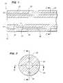
- FIG. 1is a sectional view of the distal end of a sheath, with lighting and imaging fiber bundles passing therethrough, prior to attaching a novel clear distal tip, in accordance with the present invention. (Corresponding to line 1 — 1 in FIG. 2 ).
- FIG. 2is a sectional view taken along line 2 — 2 in FIG. 1 .
- FIG. 3shows the attachment of the clear distal tip to the sheath/fiber bundle structure of FIG. 1 .
- FIG. 4is a sectional view of the distal end of a common pre-existing endoscope design.
- FIG. 5is a sectional view of an alternative embodiment of the distal tip.
- FIG. 6is a sectional view taken along line 6 — 6 in FIG. 2 showing an optional embodiment of the present invention with pull wires passing through the distal tip.
- FIGS. 1 and 2show the sheath 20 /fiber bundles 30 , 40 of the present endoscope 10 .
- the sheath 20has three lumen 22 , 32 , 42 passing therealong. It is to be understood that sheaths 20 having additional (or fewer) lumen are also encompassed by the present invention.
- a fiber optic lighting bundle 30is received in a first lumen 32 and a fiber optic imaging bundle 40 is received in a second lumen 42 .
- the third lumen 22is left open and functions as a large central working channel 50 .
- the system of FIGS. 1 and 2is first assembled, and thereafter the distal tip 60 shown in FIG. 3 is attached.
- the distal tip 60 shown in FIG. 3will preferably be made of a light transmitting or more preferably “clear” material.
- Exemplary light transmitting materialsinclude glass and plastic. It is to be understood, however, that the present invention also encompasses embodiments in which the distal tip 60 is not clear, with light instead passing through a lumen in the distal tip 60 .
- An advantage of manufacturing the present system by first assembling the components of FIGS. 1 and 2 , and then attaching the clear distal tip 60 of FIG. 3is as follows.
- very long sections of sheath 20can be made with imaging 40 and lighting bundles 30 pre-fit therein. Then, these very long sections of sheath 20 /fiber bundles 30 , 40 can be cut into individual endoscopes 10 of desired lengths. At the time of this cutting, both the sheath 20 and the fiber (lighting and imaging) bundles 30 , 40 disposed therein will be cut cleanly together at its distal end 12 .
- the distal ends 12 of the imaging and lighting bundles 40 , 30will be polished when they are cut. If the bundles 30 , 40 are plastic, the cutting and polishing may be done with a hot wire. Alternatively, if the bundles 30 , 40 are glass, they can be simultaneously cut, ground and polished.
- a result of performing a single cut through the sheath 20 and its imaging and lighting bundles 40 , 30results in the distal ends 12 of these three elements all being co-planar to one another.
- pre-existing endoscopes 100did not have the distal ends 102 of the imaging and lighting bundles 130 , 120 disposed co-planar to one another. This was due to the fact that an objective lens 140 needs to be attached to the distal end of the imaging bundle 130 . (An example of such a pre-existing system is shown in FIG. 4 .)
- these pre-existing endoscopes 100did not cut/polish the ends of the imaging and lighting bundles 120 , 130 together as is conveniently accomplished by the present invention. Rather, these common pre-existing endoscopes 100 were assembled by first cutting the sheath 110 to a desired length, and then separately cutting and polishing the distal ends 132 , 122 of the imaging and lighting bundles 130 , 120 , slipping a ferrule (metal ring) around the distal end 132 of the imaging bundle 130 and then inserting each of the imaging and lighting bundles 130 , 120 into separate lumens in the sheath 110 . As such, the ferrule is used to connect the lens 140 and the distal end 132 of the imaging fiber 130 together.
- the present inventionis thus able to simplify manufacturing steps considerably by positioning the distal ends 44 , 34 of the imaging and lighting bundles 40 , 30 co-planar to one another.
- the objective lens 70is positioned in alignment with, and distal to, the imaging bundle 40 without the distal end 34 of the lighting bundle 30 having to be co-planar with the distal end 74 of the objective lens 70 (as in FIG. 4 ), by instead using a novel “clear tip” distal end 60 , as follows.
- a “clear” distal tip 60is received over the distal end 12 , of components FIGS. 1 and 2 .
- This distal tip 60may preferably be made from glass, or more preferably, from plastic.
- a first advantage of the distal tip 60 being made of a clear materialis that light from the end of the lighting bundle 30 will diffuse therethrough such that the target tissue will be illuminated even though the distal end 34 of the lighting bundle 30 is positioned proximally (i.e. upstream) of the distal end 74 of the objective lens 70 .
- the light exiting the lighting bundle 30may diffuse widely, thereby illuminating a larger tissue surface area than could be accomplished with a pre-existing system as shown in FIG. 4 where the distal end 122 of the lighting bundle 120 and the objective lens 140 are co-planar.
- materials having a higher index of refractioncould potentially exhibit more diffuse lighting therethrough, thus illumination a greater tissue surface area.
- a second advantage of the present distal tip 60is that it can be pre-fitted with the objective lens 70 therein. (This advantage is true even if the distal tip 60 is not made of a clear material). As such, there is no need to attach, or otherwise position, the objective lens 70 to the distal end 44 of the imaging bundle 40 (as was done, for example in the prior art system seen in FIG. 4 ).
- a disadvantage of the approach seen in the pre-existing system of FIG. 4is that, by gluing the objective lens 140 to the imaging bundle 130 , partial or complete lens separation from the imaging bundle 130 can occur. Such lens 140 separations tend to disrupt the picture, most notably by producing rainbow effects.
- the lens 70would preferably be mounted into the distal tip 60 with an appropriate anti-reflective coating to assure optimal image transmission.
- the lens 70 and tip carriercould be could be made as separate components and then assembled into the distal tip 60 .
- a third advantage of the system shown in FIG. 3is that an air space “gap” 72 is preferably provided between the distal end 44 of the imaging bundle 40 and the proximal end 76 of the objective lens 70 .
- This featureis not seen in any pre-existing system. It offers many advantages. For example, the bending stresses in the imaging bundle 40 are not transmitted to the objective lens 70 at all. Moreover, frequencies of light which may cause the imaging (and lighting) bundles 40 , 30 to overheat would not necessarily cause the objective lens 70 to overheat, since heat from the bundle(s) 30 , 40 would not be conducted directly into the lens 70 , due to the presence of the “air gap” 72 .
- an “air gap” 72 between the distal end 44 of the imaging bundle 40 and the proximal end 76 of the lens 70would still be advantageous even in those embodiments in which the distal end 32 is not clear (i.e.: in which light from the lighting bundle 30 instead passes through a lumen in the distal tip 60 ).
- a fourth advantage of the present clear tip designis that it can be easily attached to the distal end 12 of the endoscope 10 .
- a thin layer of adhesive 80can be provided between the inner surface 62 of the clear tip 60 and the outer surface 26 of the sheath ( FIG. 3 ). Any medically acceptable adhesive that will not damage the optical surface of the instrument is potentially of use in the invention.
- this thin adhesive layer 80can be made from a UV curable adhesive, for example a UV-curable epoxy adhesive.
- the epoxywill “cure”.
- a distinct advantage of the present clear tip designis that such UV light will simply pass through the tip 60 and reach the epoxy disposed thereunder.
- the present epoxycan be cured by UV light although it is positioned between two separate components of the system. This advantageously reduces manufacturing steps and their associated costs.
- Another useful feature of the design as shownis that the adhesive 80 is not in the light path, minimizing potential interference of the adhesive 80 with image quality or brightness. It can be appreciated that any suitable adhesive 80 , which can reliably adhere the tip 60 to the outer surface 26 of the sheath 20 can be used.
- adhesives 80can also be used.
- sonic or heat weldingcan join parts, especially plastic parts.
- detents or other mechanical interlocksis possible, but might raise costs. Interference fits are possible, but it will generally be better to supplement such contacts with adhesive, for safety.
- a fifth advantage of the clear tip 60is that it can be made of a material which only passes selective wavelengths of light therethrough. This can be advantageous when using therapeutic compounds which are activated by specific frequencies of light.
- the clear tipis preferably constructed optionally with lenses to focus and distribute the illuminating light in the area, which is imaged by the imaging lens.
- FIG. 5An alternative shape of the tip 60 is shown in FIG. 5 .
- the tip 60has curved surfaces 68 in it, so it can act as a lens, especially for the imaging fiber bundle 40 .
- Such surfaces 68can be cast integrally with the tip 60 during its manufacture, for example by injection molding.
- the surfaces 68are simple curves, but aspheric surfaces may be preferred so as to focus as much light as possible on the entrance pupil of the fiber bundle 30 , 40 . If required, a corresponding aspheric could be positioned at the exit of the fiber bundle 30 , 40 to reshape the image.
- a second alternative feature also shown in FIG. 5is a projection rim 90 that fits inside the central working lumen 50 . Either by closeness of fit, or by virtue of adhesive for a reliable seal, the rim 90 seals the empty optical space so that fluid cannot get into the optical path during the procedure.
- the clear tip 60also has a central working channel 52 passing therethrough, which can be placed in alignment with the working channel 50 of the sheath 20 , permitting tool or irrigation access therethrough.
- the distal tip 60may be cylindrical. More preferably, the distal end 64 of the distal tip 60 can be beveled or curved to minimize the potential for tissue trauma as the endoscope 10 is advanced into the patient.
- FIG. 6shows an embodiment of the present invention corresponding to a view taken along line 6 - 6 in FIG. 2 , showing optional pull wires 94 passing through the distal tip 60 .
- the drawingillustrates a useful design option that can simplify assembly.
- a funnel-shaped 98 feature in the distal tip 60retains the pull wire 94 .
- the wires 94can be threaded into the endoscope 10 after the distal tip 60 is bonded in place, simplifying assembly.
- the application of force to pull wires 94will tend to pull the tip 60 against the distal sheath 20 .
- the pull wires 94can be inserted in such a slot in the sheath 20 , and then the tip 60 , optionally lacking openings for pull wires 94 would be bonded in place.
- the endoscope 10has been illustrated with two pull wire lumens 16 , a working lumen 52 , and one lumen 32 , 42 each for lighting and imaging. This is a minimal configuration, and embodiments having more lumens are within the scope of the invention. For example, there could be three or four pull wire lumens 16 , and two or three lighting lumens, for example as shown in U.S. Pat. No. 6,458,076, by the same inventor.
Landscapes
- Health & Medical Sciences (AREA)
- Life Sciences & Earth Sciences (AREA)
- Surgery (AREA)
- Optics & Photonics (AREA)
- Physics & Mathematics (AREA)
- Nuclear Medicine, Radiotherapy & Molecular Imaging (AREA)
- Medical Informatics (AREA)
- Radiology & Medical Imaging (AREA)
- Biophysics (AREA)
- Engineering & Computer Science (AREA)
- Biomedical Technology (AREA)
- Heart & Thoracic Surgery (AREA)
- Pathology (AREA)
- Molecular Biology (AREA)
- Animal Behavior & Ethology (AREA)
- General Health & Medical Sciences (AREA)
- Public Health (AREA)
- Veterinary Medicine (AREA)
- Endoscopes (AREA)
Abstract
Description
Claims (20)
Priority Applications (1)
| Application Number | Priority Date | Filing Date | Title |
|---|---|---|---|
| US10/863,874US7033317B2 (en) | 2003-06-05 | 2004-06-07 | Disposable endoscope and method of making a disposable endoscope |
Applications Claiming Priority (2)
| Application Number | Priority Date | Filing Date | Title |
|---|---|---|---|
| US47647403P | 2003-06-05 | 2003-06-05 | |
| US10/863,874US7033317B2 (en) | 2003-06-05 | 2004-06-07 | Disposable endoscope and method of making a disposable endoscope |
Publications (2)
| Publication Number | Publication Date |
|---|---|
| US20050043589A1 US20050043589A1 (en) | 2005-02-24 |
| US7033317B2true US7033317B2 (en) | 2006-04-25 |
Family
ID=33551607
Family Applications (1)
| Application Number | Title | Priority Date | Filing Date |
|---|---|---|---|
| US10/863,874Expired - Fee RelatedUS7033317B2 (en) | 2003-06-05 | 2004-06-07 | Disposable endoscope and method of making a disposable endoscope |
Country Status (2)
| Country | Link |
|---|---|
| US (1) | US7033317B2 (en) |
| WO (1) | WO2005000096A2 (en) |
Cited By (48)
| Publication number | Priority date | Publication date | Assignee | Title |
|---|---|---|---|---|
| US20030220574A1 (en)* | 2002-03-18 | 2003-11-27 | Sarcos Investments Lc. | Miniaturized imaging device including utility aperture and SSID |
| US20060276692A1 (en)* | 2005-06-01 | 2006-12-07 | Cannuflow Incorporated | Protective cap for arthroscopic instruments |
| US20080304143A1 (en)* | 2007-06-05 | 2008-12-11 | Jacobsen Stephen C | Mini-scope for multi-directional imaging |
| US20090180197A1 (en)* | 2008-01-11 | 2009-07-16 | Sterling Lc | Grin lens microscope system |
| US20090287048A1 (en)* | 2008-05-16 | 2009-11-19 | Sterling Lc | Method and apparatus for imaging within a living body |
| US20100188492A1 (en)* | 2008-07-30 | 2010-07-29 | Jacobsen Stephen C | Method And Device For Incremental Wavelength Variation To Analyze Tissue |
| US20110211104A1 (en)* | 2008-11-14 | 2011-09-01 | Koninklijke Philips Electronics N.V. | Optical fiber scanning probe |
| US20110295072A1 (en)* | 2006-04-20 | 2011-12-01 | Boston Scientific Scimed, Inc. | Imaging assembly with transparent distal cap |
| US8088163B1 (en) | 2008-02-06 | 2012-01-03 | Kleiner Jeffrey B | Tools and methods for spinal fusion |
| USD656610S1 (en) | 2009-02-06 | 2012-03-27 | Kleiner Jeffrey B | Spinal distraction instrument |
| US8366748B2 (en) | 2008-12-05 | 2013-02-05 | Kleiner Jeffrey | Apparatus and method of spinal implant and fusion |
| US20130197311A1 (en)* | 2010-04-12 | 2013-08-01 | Cleanoscope Inc. | Lens protector for endoscopic devices |
| US8614768B2 (en) | 2002-03-18 | 2013-12-24 | Raytheon Company | Miniaturized imaging device including GRIN lens optically coupled to SSID |
| US8685031B2 (en) | 2009-09-18 | 2014-04-01 | Spinal Surgical Strategies, Llc | Bone graft delivery system |
| US8690762B2 (en) | 2008-06-18 | 2014-04-08 | Raytheon Company | Transparent endoscope head defining a focal length |
| US8717428B2 (en) | 2009-10-01 | 2014-05-06 | Raytheon Company | Light diffusion apparatus |
| US20140163317A1 (en)* | 2012-12-07 | 2014-06-12 | Cook Medical Technologies Llc | Flexible lens |
| US8828028B2 (en) | 2009-11-03 | 2014-09-09 | Raytheon Company | Suture device and method for closing a planar opening |
| US8864654B2 (en) | 2010-04-20 | 2014-10-21 | Jeffrey B. Kleiner | Method and apparatus for performing retro peritoneal dissection |
| US8906028B2 (en) | 2009-09-18 | 2014-12-09 | Spinal Surgical Strategies, Llc | Bone graft delivery device and method of using the same |
| US8905921B2 (en) | 2011-02-16 | 2014-12-09 | The General Hospital Corporation | Optical coupler for an endoscope |
| USD723682S1 (en) | 2013-05-03 | 2015-03-03 | Spinal Surgical Strategies, Llc | Bone graft delivery tool |
| US20150080896A1 (en) | 2013-07-19 | 2015-03-19 | Ouroboros Medical, Inc. | Anti-clogging device for a vacuum-assisted, tissue removal system |
| US9060877B2 (en) | 2009-09-18 | 2015-06-23 | Spinal Surgical Strategies, Llc | Fusion cage with combined biological delivery system |
| US9060704B2 (en) | 2008-11-04 | 2015-06-23 | Sarcos Lc | Method and device for wavelength shifted imaging |
| US9119659B2 (en) | 2011-12-03 | 2015-09-01 | Ouroboros Medical, Inc. | Safe cutting heads and systems for fast removal of a target tissue |
| US9144664B2 (en) | 2009-10-01 | 2015-09-29 | Sarcos Lc | Method and apparatus for manipulating movement of a micro-catheter |
| US9173694B2 (en) | 2009-09-18 | 2015-11-03 | Spinal Surgical Strategies, Llc | Fusion cage with combined biological delivery system |
| US9186193B2 (en) | 2009-09-18 | 2015-11-17 | Spinal Surgical Strategies, Llc | Fusion cage with combined biological delivery system |
| US9238122B2 (en) | 2012-01-26 | 2016-01-19 | Covidien Lp | Thrombectomy catheter systems |
| US9247943B1 (en) | 2009-02-06 | 2016-02-02 | Kleiner Intellectual Property, Llc | Devices and methods for preparing an intervertebral workspace |
| USD750249S1 (en) | 2014-10-20 | 2016-02-23 | Spinal Surgical Strategies, Llc | Expandable fusion cage |
| WO2016064449A1 (en) | 2014-10-20 | 2016-04-28 | Research Development International Corporation | Steerable micro-endoscope |
| US9459442B2 (en) | 2014-09-23 | 2016-10-04 | Scott Miller | Optical coupler for optical imaging visualization device |
| US9629729B2 (en) | 2009-09-18 | 2017-04-25 | Spinal Surgical Strategies, Llc | Biological delivery system with adaptable fusion cage interface |
| US9661996B2 (en) | 2009-10-01 | 2017-05-30 | Sarcos Lc | Needle delivered imaging device |
| US9717403B2 (en) | 2008-12-05 | 2017-08-01 | Jeffrey B. Kleiner | Method and apparatus for performing retro peritoneal dissection |
| USD797290S1 (en) | 2015-10-19 | 2017-09-12 | Spinal Surgical Strategies, Llc | Bone graft delivery tool |
| US9943214B2 (en) | 2014-07-02 | 2018-04-17 | Xenocor, Inc. | Medical borescopes and related methods and systems |
| US10245159B1 (en) | 2009-09-18 | 2019-04-02 | Spinal Surgical Strategies, Llc | Bone graft delivery system and method for using same |
| USD853560S1 (en) | 2008-10-09 | 2019-07-09 | Nuvasive, Inc. | Spinal implant insertion device |
| US10548467B2 (en) | 2015-06-02 | 2020-02-04 | GI Scientific, LLC | Conductive optical element |
| US10856724B2 (en) | 2015-07-21 | 2020-12-08 | GI Scientific, LLC | Endoscope accessory with angularly adjustable exit portal |
| US10973656B2 (en) | 2009-09-18 | 2021-04-13 | Spinal Surgical Strategies, Inc. | Bone graft delivery system and method for using same |
| US11324387B2 (en) | 2014-07-02 | 2022-05-10 | Xenocor, Inc. | Medical borescopes and related tip assemblies |
| US11666455B2 (en) | 2009-09-18 | 2023-06-06 | Spinal Surgical Strategies, Inc., A Nevada Corporation | Bone graft delivery devices, systems and kits |
| US11903557B2 (en) | 2019-04-30 | 2024-02-20 | Psip2 Llc | Endoscope for imaging in nonvisible light |
| US12279972B2 (en) | 2008-05-22 | 2025-04-22 | Spinal Surgical Strategies, Inc. | Spinal fusion cage system with inserter |
Families Citing this family (8)
| Publication number | Priority date | Publication date | Assignee | Title |
|---|---|---|---|---|
| CA2590737A1 (en) | 2004-12-09 | 2006-06-15 | Virochem Pharma Inc. | Novel spirotropane compounds and methods for the modulation of chemokine receptor activity |
| US20070260273A1 (en)* | 2006-05-08 | 2007-11-08 | Ethicon Endo-Surgery, Inc. | Endoscopic Translumenal Surgical Systems |
| US20070260121A1 (en)* | 2006-05-08 | 2007-11-08 | Ethicon Endo-Surgery, Inc. | Endoscopic Translumenal Surgical Systems |
| US7583876B2 (en)* | 2006-06-30 | 2009-09-01 | Schott Corporation | Illuminable image-conducting optical assembly including light-conductive optics housing for creating an illuminating halo |
| JP2012509159A (en)* | 2008-11-19 | 2012-04-19 | コーニンクレッカ フィリップス エレクトロニクス エヌ ヴィ | Needle with built-in fiber |
| EP2830495A1 (en)* | 2012-03-30 | 2015-02-04 | Koninklijke Philips N.V. | Medical needle |
| US11026676B2 (en)* | 2017-02-06 | 2021-06-08 | Covidien Lp | Surgical wound closure apparatus |
| US20220354350A1 (en)* | 2021-05-06 | 2022-11-10 | Karl Storz Endovision, Inc. | Endoscope Heads With Light-Permeable Housing and Method of Manufacturing Endoscope Heads |
Citations (44)
| Publication number | Priority date | Publication date | Assignee | Title |
|---|---|---|---|---|
| US4392485A (en) | 1981-02-17 | 1983-07-12 | Richard Wolf Gmbh | Endoscope |
| US4580551A (en) | 1984-11-02 | 1986-04-08 | Warner-Lambert Technologies, Inc. | Flexible plastic tube for endoscopes and the like |
| US4706656A (en) | 1985-05-15 | 1987-11-17 | Olympus Optical Co., Ltd. | Endoscope device with tool channel |
| US4784144A (en) | 1982-07-31 | 1988-11-15 | Sumitomo Electric Industries, Ltd. | Optical fiber image sensor |
| US4872740A (en) | 1987-02-12 | 1989-10-10 | Mitsubishi Rayon Company, Ltd. | Endoscope |
| US4892099A (en) | 1984-07-18 | 1990-01-09 | Sumitomo Electric Industries, Ltd. | Catheter |
| US4911148A (en) | 1989-03-14 | 1990-03-27 | Intramed Laboratories, Inc. | Deflectable-end endoscope with detachable flexible shaft assembly |
| US4919112A (en) | 1989-04-07 | 1990-04-24 | Schott Fiber Optics | Low-cost semi-disposable endoscope |
| US4947827A (en) | 1988-12-30 | 1990-08-14 | Opielab, Inc. | Flexible endoscope |
| WO1991015793A1 (en) | 1990-04-11 | 1991-10-17 | Washington University | Endoscope with single plastic fiber optic bundle |
| US5140975A (en) | 1991-02-15 | 1992-08-25 | Welch Allyn, Inc. | Insertion tube assembly for probe with biased bending neck |
| US5188092A (en) | 1990-12-13 | 1993-02-23 | United States Surgical Corporation | Disposable rigid endoscope |
| WO1993015647A1 (en) | 1992-02-06 | 1993-08-19 | Linvatec Corporation | Disposable endoscope |
| US5241970A (en) | 1991-05-17 | 1993-09-07 | Wilson-Cook Medical, Inc. | Papillotome/sphincterotome procedures and a wire guide specially |
| US5307803A (en) | 1992-03-04 | 1994-05-03 | Intramed Laboratories | Deflecting endoscope |
| US5320602A (en) | 1993-05-14 | 1994-06-14 | Wilson-Cook Medical, Inc. | Peel-away endoscopic retrograde cholangio pancreatography catheter and a method for using the same |
| US5325845A (en) | 1992-06-08 | 1994-07-05 | Adair Edwin Lloyd | Steerable sheath for use with selected removable optical catheter |
| US5397302A (en) | 1992-05-11 | 1995-03-14 | Arrow Precision Products, Inc. | Method of using a dual lumen biliary catheter |
| US5398687A (en) | 1992-05-18 | 1995-03-21 | Wilson-Cook Medical Inc. | Methods for measuring motility within the biliary tract and instrumentation useful therefor |
| US5458112A (en) | 1994-08-15 | 1995-10-17 | Arrow Precision Products, Inc. | Biliary biopsy device |
| US5547457A (en)* | 1993-01-22 | 1996-08-20 | Olympus Optical Co., Ltd. | Objective optical system for endoscopes |
| US5549542A (en) | 1992-11-17 | 1996-08-27 | Life Medical Technologies, Inc. | Deflectable endoscope |
| US5555131A (en) | 1994-10-27 | 1996-09-10 | Symbiosis Corporation | Objective lens system for endoscope |
| US5704899A (en) | 1995-10-10 | 1998-01-06 | Conceptus, Inc. | Protective sheath for a fiberoptic image guide within an articulated endoscope |
| WO1998001074A1 (en) | 1996-07-08 | 1998-01-15 | Boston Scientific Corporation | Diagnosing and performing interventional procedures on tissue in vivo |
| US5779624A (en) | 1996-12-05 | 1998-07-14 | Boston Scientific Corporation | Sigmoid splint device for endoscopy |
| US5788681A (en) | 1992-05-11 | 1998-08-04 | Medical Innovations Corporation | Multi-lumen endoscopic catheter |
| US5834214A (en) | 1992-12-24 | 1998-11-10 | Institut National De La Sante Et De La Recherche Medicale | Detection of pancreatitis-associated protein for screening for cystic fibrosis |
| US5892630A (en) | 1992-02-10 | 1999-04-06 | Linvatec Corporation | Disposable endoscope |
| US5916147A (en) | 1997-09-22 | 1999-06-29 | Boury; Harb N. | Selectively manipulable catheter |
| US5938585A (en) | 1998-03-20 | 1999-08-17 | Boston Scientific Corporation | Anchoring and positioning device and method for an endoscope |
| US5960145A (en) | 1997-01-21 | 1999-09-28 | Sanchez; Jorge O. | Optical fiber image conduit and method using same |
| US6010449A (en) | 1997-02-28 | 2000-01-04 | Lumend, Inc. | Intravascular catheter system for treating a vascular occlusion |
| US6013024A (en) | 1997-01-20 | 2000-01-11 | Suzuki Motor Corporation | Hybrid operation system |
| US6099485A (en) | 1996-08-27 | 2000-08-08 | C. R. Bard, Inc. | Torquable, low mass medical guidewire |
| WO2000054653A1 (en) | 1999-03-12 | 2000-09-21 | Boston Scientific Limited | Controllable endoscopic sheath |
| US6146389A (en) | 1998-04-23 | 2000-11-14 | Boston Scientific Corporation | Stent deployment device and method for deploying a stent |
| US6184923B1 (en)* | 1994-11-25 | 2001-02-06 | Olympus Optical Co., Ltd. | Endoscope with an interchangeable distal end optical adapter |
| US6213974B1 (en) | 1996-12-30 | 2001-04-10 | Visionary Biomedical, Inc. | Steerable catheter having segmented tip and one-piece inlet housing, and method of fabricating same |
| US6217510B1 (en) | 1997-10-02 | 2001-04-17 | Olympus Optical Co., Ltd. | Endoscopes and endoscope devices which image regular observation images and fluorescent images as well as which provide easier operation of treatment tools |
| US20020099267A1 (en)* | 2001-01-25 | 2002-07-25 | Scimed Life Systems, Inc. | Endoscopic vision system |
| US20020186478A1 (en)* | 2001-06-07 | 2002-12-12 | Fuji Photo Optical Co., Ltd. | Lens assembly for endoscopic lens system |
| US20040143162A1 (en)* | 2001-04-27 | 2004-07-22 | Beat Krattiger | Optical instrument, in particular an endoscope, having an interchangeable head |
| US20050014996A1 (en)* | 2003-04-11 | 2005-01-20 | Yutaka Konomura | Optical adaptor and endoscope device |
Family Cites Families (13)
| Publication number | Priority date | Publication date | Assignee | Title |
|---|---|---|---|---|
| US4321038A (en)* | 1980-07-18 | 1982-03-23 | Van R Dental Products, Inc. | Braided gingival retraction cord |
| US4465462A (en)* | 1983-04-27 | 1984-08-14 | Ticknor Verne E | Gingival retraction cord |
| US4522593A (en)* | 1983-07-07 | 1985-06-11 | Fischer Dan E | Knitted gingival retraction cord |
| US4617950A (en)* | 1985-04-22 | 1986-10-21 | Van R Dental Products, Inc. | Gingival retraction cord with wet, drip-free astringent |
| SE458984B (en)* | 1986-05-26 | 1989-05-29 | Leif Hagne | PROCEDURAL AND RETIREMENT STRATEGY FOR EXPOSURE AND TARGETING OF THE LIMIT OF PREPARATION ON TIRE |
| US4892482A (en)* | 1988-08-30 | 1990-01-09 | Lococo Michael P | Dental retraction cord |
| US5022859A (en)* | 1989-10-10 | 1991-06-11 | Oliva Richard A | Gingival rectractor instrument |
| US5834028A (en)* | 1993-12-17 | 1998-11-10 | Mochida Pharmaceutical Co., Ltd. | Soluble thrombomodulin-containing composition |
| US5540588A (en)* | 1994-11-02 | 1996-07-30 | Earle; Jeffrey O. | Teflon-coated intraoral tissue retraction cord |
| US5676543A (en)* | 1995-03-08 | 1997-10-14 | Centrix, Inc. | Gum tissue retraction device and method |
| US5899694A (en)* | 1998-02-20 | 1999-05-04 | Summer; John | Gingival retraction apparatus and method |
| US6375461B1 (en)* | 2000-09-18 | 2002-04-23 | Ultradent Products, Inc. | Gingival retraction cords incorporating propylhexedrine |
| US6612839B2 (en)* | 2001-04-04 | 2003-09-02 | Murgesh J. Loynes | Gingival retractor |
- 2004
- 2004-06-07WOPCT/US2004/017962patent/WO2005000096A2/enactiveApplication Filing
- 2004-06-07USUS10/863,874patent/US7033317B2/ennot_activeExpired - Fee Related
Patent Citations (51)
| Publication number | Priority date | Publication date | Assignee | Title |
|---|---|---|---|---|
| US4392485A (en) | 1981-02-17 | 1983-07-12 | Richard Wolf Gmbh | Endoscope |
| US4784144A (en) | 1982-07-31 | 1988-11-15 | Sumitomo Electric Industries, Ltd. | Optical fiber image sensor |
| US4892099A (en) | 1984-07-18 | 1990-01-09 | Sumitomo Electric Industries, Ltd. | Catheter |
| US4580551A (en) | 1984-11-02 | 1986-04-08 | Warner-Lambert Technologies, Inc. | Flexible plastic tube for endoscopes and the like |
| US4706656A (en) | 1985-05-15 | 1987-11-17 | Olympus Optical Co., Ltd. | Endoscope device with tool channel |
| US4872740A (en) | 1987-02-12 | 1989-10-10 | Mitsubishi Rayon Company, Ltd. | Endoscope |
| US4947827A (en) | 1988-12-30 | 1990-08-14 | Opielab, Inc. | Flexible endoscope |
| US4911148A (en) | 1989-03-14 | 1990-03-27 | Intramed Laboratories, Inc. | Deflectable-end endoscope with detachable flexible shaft assembly |
| US4919112A (en) | 1989-04-07 | 1990-04-24 | Schott Fiber Optics | Low-cost semi-disposable endoscope |
| US4919112B1 (en) | 1989-04-07 | 1993-12-28 | Low-cost semi-disposable endoscope | |
| WO1991015793A1 (en) | 1990-04-11 | 1991-10-17 | Washington University | Endoscope with single plastic fiber optic bundle |
| US5188092A (en) | 1990-12-13 | 1993-02-23 | United States Surgical Corporation | Disposable rigid endoscope |
| US5140975A (en) | 1991-02-15 | 1992-08-25 | Welch Allyn, Inc. | Insertion tube assembly for probe with biased bending neck |
| US5241970A (en) | 1991-05-17 | 1993-09-07 | Wilson-Cook Medical, Inc. | Papillotome/sphincterotome procedures and a wire guide specially |
| WO1993015647A1 (en) | 1992-02-06 | 1993-08-19 | Linvatec Corporation | Disposable endoscope |
| US5341240A (en) | 1992-02-06 | 1994-08-23 | Linvatec Corporation | Disposable endoscope |
| US5416638A (en) | 1992-02-06 | 1995-05-16 | Linvatec Corporation | Disposable endoscope |
| US5519532A (en) | 1992-02-06 | 1996-05-21 | Linvatec Corporation | Disposable endoscope |
| US5892630A (en) | 1992-02-10 | 1999-04-06 | Linvatec Corporation | Disposable endoscope |
| US5307803A (en) | 1992-03-04 | 1994-05-03 | Intramed Laboratories | Deflecting endoscope |
| US5397302A (en) | 1992-05-11 | 1995-03-14 | Arrow Precision Products, Inc. | Method of using a dual lumen biliary catheter |
| US5843028A (en) | 1992-05-11 | 1998-12-01 | Medical Innovations Corporation | Multi-lumen endoscopic catheter |
| US5788681A (en) | 1992-05-11 | 1998-08-04 | Medical Innovations Corporation | Multi-lumen endoscopic catheter |
| US5599299A (en) | 1992-05-11 | 1997-02-04 | Arrow Precision Products, Inc. | Multi-lumen endoscopic catheter |
| US5398687A (en) | 1992-05-18 | 1995-03-21 | Wilson-Cook Medical Inc. | Methods for measuring motility within the biliary tract and instrumentation useful therefor |
| US5325845A (en) | 1992-06-08 | 1994-07-05 | Adair Edwin Lloyd | Steerable sheath for use with selected removable optical catheter |
| US5549542A (en) | 1992-11-17 | 1996-08-27 | Life Medical Technologies, Inc. | Deflectable endoscope |
| US5834214A (en) | 1992-12-24 | 1998-11-10 | Institut National De La Sante Et De La Recherche Medicale | Detection of pancreatitis-associated protein for screening for cystic fibrosis |
| US5547457A (en)* | 1993-01-22 | 1996-08-20 | Olympus Optical Co., Ltd. | Objective optical system for endoscopes |
| US5320602A (en) | 1993-05-14 | 1994-06-14 | Wilson-Cook Medical, Inc. | Peel-away endoscopic retrograde cholangio pancreatography catheter and a method for using the same |
| US5458112A (en) | 1994-08-15 | 1995-10-17 | Arrow Precision Products, Inc. | Biliary biopsy device |
| US5555131A (en) | 1994-10-27 | 1996-09-10 | Symbiosis Corporation | Objective lens system for endoscope |
| US6184923B1 (en)* | 1994-11-25 | 2001-02-06 | Olympus Optical Co., Ltd. | Endoscope with an interchangeable distal end optical adapter |
| US5704899A (en) | 1995-10-10 | 1998-01-06 | Conceptus, Inc. | Protective sheath for a fiberoptic image guide within an articulated endoscope |
| WO1998001074A1 (en) | 1996-07-08 | 1998-01-15 | Boston Scientific Corporation | Diagnosing and performing interventional procedures on tissue in vivo |
| US6099485A (en) | 1996-08-27 | 2000-08-08 | C. R. Bard, Inc. | Torquable, low mass medical guidewire |
| US5779624A (en) | 1996-12-05 | 1998-07-14 | Boston Scientific Corporation | Sigmoid splint device for endoscopy |
| US6213974B1 (en) | 1996-12-30 | 2001-04-10 | Visionary Biomedical, Inc. | Steerable catheter having segmented tip and one-piece inlet housing, and method of fabricating same |
| US6013024A (en) | 1997-01-20 | 2000-01-11 | Suzuki Motor Corporation | Hybrid operation system |
| US5960145A (en) | 1997-01-21 | 1999-09-28 | Sanchez; Jorge O. | Optical fiber image conduit and method using same |
| US6010449A (en) | 1997-02-28 | 2000-01-04 | Lumend, Inc. | Intravascular catheter system for treating a vascular occlusion |
| US5916147A (en) | 1997-09-22 | 1999-06-29 | Boury; Harb N. | Selectively manipulable catheter |
| US6217510B1 (en) | 1997-10-02 | 2001-04-17 | Olympus Optical Co., Ltd. | Endoscopes and endoscope devices which image regular observation images and fluorescent images as well as which provide easier operation of treatment tools |
| US5938585A (en) | 1998-03-20 | 1999-08-17 | Boston Scientific Corporation | Anchoring and positioning device and method for an endoscope |
| US6277065B1 (en) | 1998-03-20 | 2001-08-21 | Boston Scientific Corporation | Anchoring and positioning device and method for an endoscope |
| US6146389A (en) | 1998-04-23 | 2000-11-14 | Boston Scientific Corporation | Stent deployment device and method for deploying a stent |
| WO2000054653A1 (en) | 1999-03-12 | 2000-09-21 | Boston Scientific Limited | Controllable endoscopic sheath |
| US20020099267A1 (en)* | 2001-01-25 | 2002-07-25 | Scimed Life Systems, Inc. | Endoscopic vision system |
| US20040143162A1 (en)* | 2001-04-27 | 2004-07-22 | Beat Krattiger | Optical instrument, in particular an endoscope, having an interchangeable head |
| US20020186478A1 (en)* | 2001-06-07 | 2002-12-12 | Fuji Photo Optical Co., Ltd. | Lens assembly for endoscopic lens system |
| US20050014996A1 (en)* | 2003-04-11 | 2005-01-20 | Yutaka Konomura | Optical adaptor and endoscope device |
Cited By (117)
| Publication number | Priority date | Publication date | Assignee | Title |
|---|---|---|---|---|
| US8614768B2 (en) | 2002-03-18 | 2013-12-24 | Raytheon Company | Miniaturized imaging device including GRIN lens optically coupled to SSID |
| US7787939B2 (en) | 2002-03-18 | 2010-08-31 | Sterling Lc | Miniaturized imaging device including utility aperture and SSID |
| US20030220574A1 (en)* | 2002-03-18 | 2003-11-27 | Sarcos Investments Lc. | Miniaturized imaging device including utility aperture and SSID |
| US9833134B2 (en)* | 2005-06-01 | 2017-12-05 | Cannuflow, Inc. | Protective cap for arthroscopic instruments |
| US20060276692A1 (en)* | 2005-06-01 | 2006-12-07 | Cannuflow Incorporated | Protective cap for arthroscopic instruments |
| US7553278B2 (en)* | 2005-06-01 | 2009-06-30 | Cannuflow, Inc. | Protective cap for arthroscopic instruments |
| US8216131B2 (en)* | 2005-06-01 | 2012-07-10 | Cannuflow, Inc. | Protective cap for arthroscopic instruments |
| US20160045105A1 (en)* | 2005-06-01 | 2016-02-18 | Cannuflow, Inc. | Protective cap for arthroscopic instruments |
| US20090326328A1 (en)* | 2005-06-01 | 2009-12-31 | Cannuflow Incorporated | Protective Cap for Arthroscopic Instruments |
| US9167955B2 (en) | 2005-06-01 | 2015-10-27 | Cannuflow, Inc. | Protective cap for arthroscopic instruments |
| US20110295072A1 (en)* | 2006-04-20 | 2011-12-01 | Boston Scientific Scimed, Inc. | Imaging assembly with transparent distal cap |
| US8870753B2 (en)* | 2006-04-20 | 2014-10-28 | Boston Scientific Scimed, Inc. | Imaging assembly with transparent distal cap |
| US8358462B2 (en) | 2007-06-05 | 2013-01-22 | Jacobsen Stephen C | Mini-scope for multi-directional imaging |
| US7835074B2 (en) | 2007-06-05 | 2010-11-16 | Sterling Lc | Mini-scope for multi-directional imaging |
| US20080304143A1 (en)* | 2007-06-05 | 2008-12-11 | Jacobsen Stephen C | Mini-scope for multi-directional imaging |
| US7969659B2 (en) | 2008-01-11 | 2011-06-28 | Sterling Lc | Grin lens microscope system |
| US20090180197A1 (en)* | 2008-01-11 | 2009-07-16 | Sterling Lc | Grin lens microscope system |
| USD696399S1 (en) | 2008-02-06 | 2013-12-24 | Kleiner Intellectual Property, Llc | Spinal distraction instrument |
| US8715355B2 (en) | 2008-02-06 | 2014-05-06 | Nuvasive, Inc. | Spinal fusion cage with removable planar elements |
| US8277510B2 (en) | 2008-02-06 | 2012-10-02 | Kleiner Intellectual Property, Llc | Tools and methods for spinal fusion |
| US8088163B1 (en) | 2008-02-06 | 2012-01-03 | Kleiner Jeffrey B | Tools and methods for spinal fusion |
| US8292960B2 (en) | 2008-02-06 | 2012-10-23 | Kleiner Intellectual Property, Llc | Spinal fusion cage with removable planar elements |
| US8808305B2 (en) | 2008-02-06 | 2014-08-19 | Jeffrey B. Kleiner | Spinal fusion cage system with inserter |
| US10179054B2 (en) | 2008-02-06 | 2019-01-15 | Jeffrey B. Kleiner | Spinal fusion cage system with inserter |
| US9439782B2 (en) | 2008-02-06 | 2016-09-13 | Jeffrey B. Kleiner | Spinal fusion cage system with inserter |
| USD700322S1 (en) | 2008-02-06 | 2014-02-25 | Jeffrey B. Kleiner | Intervertebral surgical tool |
| US11129730B2 (en) | 2008-02-06 | 2021-09-28 | Spinal Surgical Strategies, Inc., a Nevada corpora | Spinal fusion cage system with inserter |
| US20090287048A1 (en)* | 2008-05-16 | 2009-11-19 | Sterling Lc | Method and apparatus for imaging within a living body |
| US12279972B2 (en) | 2008-05-22 | 2025-04-22 | Spinal Surgical Strategies, Inc. | Spinal fusion cage system with inserter |
| US8690762B2 (en) | 2008-06-18 | 2014-04-08 | Raytheon Company | Transparent endoscope head defining a focal length |
| US9521946B2 (en) | 2008-06-18 | 2016-12-20 | Sarcos Lc | Transparent endoscope head defining a focal length |
| US20100188492A1 (en)* | 2008-07-30 | 2010-07-29 | Jacobsen Stephen C | Method And Device For Incremental Wavelength Variation To Analyze Tissue |
| US8486735B2 (en) | 2008-07-30 | 2013-07-16 | Raytheon Company | Method and device for incremental wavelength variation to analyze tissue |
| US9259142B2 (en) | 2008-07-30 | 2016-02-16 | Sarcos Lc | Method and device for incremental wavelength variation to analyze tissue |
| USD853560S1 (en) | 2008-10-09 | 2019-07-09 | Nuvasive, Inc. | Spinal implant insertion device |
| US9717418B2 (en) | 2008-11-04 | 2017-08-01 | Sarcos Lc | Method and device for wavelength shifted imaging |
| US9060704B2 (en) | 2008-11-04 | 2015-06-23 | Sarcos Lc | Method and device for wavelength shifted imaging |
| US8842208B2 (en) | 2008-11-14 | 2014-09-23 | Koninklijke Philips N.V. | Optical fiber scanning probe |
| US20110211104A1 (en)* | 2008-11-14 | 2011-09-01 | Koninklijke Philips Electronics N.V. | Optical fiber scanning probe |
| US9427264B2 (en) | 2008-12-05 | 2016-08-30 | Jeffrey KLEINER | Apparatus and method of spinal implant and fusion |
| US9861496B2 (en) | 2008-12-05 | 2018-01-09 | Jeffrey B. Kleiner | Apparatus and method of spinal implant and fusion |
| US8366748B2 (en) | 2008-12-05 | 2013-02-05 | Kleiner Jeffrey | Apparatus and method of spinal implant and fusion |
| US9717403B2 (en) | 2008-12-05 | 2017-08-01 | Jeffrey B. Kleiner | Method and apparatus for performing retro peritoneal dissection |
| US8870882B2 (en) | 2008-12-05 | 2014-10-28 | Jeffrey KLEINER | Apparatus and method of spinal implant and fusion |
| US10617293B2 (en) | 2008-12-05 | 2020-04-14 | Jeffrey B. Kleiner | Method and apparatus for performing retro peritoneal dissection |
| US10201355B2 (en) | 2009-02-06 | 2019-02-12 | Kleiner Intellectual Property, Llc | Angled surgical tool for removing tissue from within an intervertebral space |
| USD656610S1 (en) | 2009-02-06 | 2012-03-27 | Kleiner Jeffrey B | Spinal distraction instrument |
| US9247943B1 (en) | 2009-02-06 | 2016-02-02 | Kleiner Intellectual Property, Llc | Devices and methods for preparing an intervertebral workspace |
| USD667542S1 (en) | 2009-02-06 | 2012-09-18 | Kleiner Jeffrey B | Spinal distraction instrument |
| US9826988B2 (en) | 2009-02-06 | 2017-11-28 | Kleiner Intellectual Property, Llc | Devices and methods for preparing an intervertebral workspace |
| US8709088B2 (en) | 2009-09-18 | 2014-04-29 | Spinal Surgical Strategies, Llc | Fusion cage with combined biological delivery system |
| US11666455B2 (en) | 2009-09-18 | 2023-06-06 | Spinal Surgical Strategies, Inc., A Nevada Corporation | Bone graft delivery devices, systems and kits |
| US8685031B2 (en) | 2009-09-18 | 2014-04-01 | Spinal Surgical Strategies, Llc | Bone graft delivery system |
| US9186193B2 (en) | 2009-09-18 | 2015-11-17 | Spinal Surgical Strategies, Llc | Fusion cage with combined biological delivery system |
| US9173694B2 (en) | 2009-09-18 | 2015-11-03 | Spinal Surgical Strategies, Llc | Fusion cage with combined biological delivery system |
| US10245159B1 (en) | 2009-09-18 | 2019-04-02 | Spinal Surgical Strategies, Llc | Bone graft delivery system and method for using same |
| US8906028B2 (en) | 2009-09-18 | 2014-12-09 | Spinal Surgical Strategies, Llc | Bone graft delivery device and method of using the same |
| US12167971B2 (en) | 2009-09-18 | 2024-12-17 | Spinal Surgical Strategies, Inc. | Bone graft delivery devices, systems and kits |
| US11660208B2 (en) | 2009-09-18 | 2023-05-30 | Spinal Surgical Strategies, Inc. | Bone graft delivery system and method for using same |
| US10195053B2 (en) | 2009-09-18 | 2019-02-05 | Spinal Surgical Strategies, Llc | Bone graft delivery system and method for using same |
| US10973656B2 (en) | 2009-09-18 | 2021-04-13 | Spinal Surgical Strategies, Inc. | Bone graft delivery system and method for using same |
| US12053393B2 (en) | 2009-09-18 | 2024-08-06 | Spinal Surgical Strategies, Inc. | Bone graft delivery system and method for use |
| US9629729B2 (en) | 2009-09-18 | 2017-04-25 | Spinal Surgical Strategies, Llc | Biological delivery system with adaptable fusion cage interface |
| US9060877B2 (en) | 2009-09-18 | 2015-06-23 | Spinal Surgical Strategies, Llc | Fusion cage with combined biological delivery system |
| US9661996B2 (en) | 2009-10-01 | 2017-05-30 | Sarcos Lc | Needle delivered imaging device |
| US9144664B2 (en) | 2009-10-01 | 2015-09-29 | Sarcos Lc | Method and apparatus for manipulating movement of a micro-catheter |
| US8717428B2 (en) | 2009-10-01 | 2014-05-06 | Raytheon Company | Light diffusion apparatus |
| US8828028B2 (en) | 2009-11-03 | 2014-09-09 | Raytheon Company | Suture device and method for closing a planar opening |
| US9521943B2 (en)* | 2010-04-12 | 2016-12-20 | Cleanoscope Inc. | Lens protector for endoscopic devices |
| US20130197311A1 (en)* | 2010-04-12 | 2013-08-01 | Cleanoscope Inc. | Lens protector for endoscopic devices |
| US8864654B2 (en) | 2010-04-20 | 2014-10-21 | Jeffrey B. Kleiner | Method and apparatus for performing retro peritoneal dissection |
| US10506918B2 (en) | 2011-02-16 | 2019-12-17 | The General Hospital Corporation | Optical coupler for an endoscope |
| US20150065795A1 (en) | 2011-02-16 | 2015-03-05 | The General Hospital Corporation | Optical Coupler for an Endoscope |
| US8905921B2 (en) | 2011-02-16 | 2014-12-09 | The General Hospital Corporation | Optical coupler for an endoscope |
| US9119659B2 (en) | 2011-12-03 | 2015-09-01 | Ouroboros Medical, Inc. | Safe cutting heads and systems for fast removal of a target tissue |
| US9265521B2 (en) | 2011-12-03 | 2016-02-23 | Ouroboros Medical, Inc. | Tissue removal systems with articulating cutting heads |
| US9220528B2 (en) | 2011-12-03 | 2015-12-29 | Ouroboros Medical, Inc. | Tubular cutter having a talon with opposing, lateral cutting surfaces |
| US10448967B2 (en) | 2011-12-03 | 2019-10-22 | DePuy Synthes Products, Inc. | Discectomy kits with an obturator, guard cannula |
| US10064643B2 (en) | 2012-01-26 | 2018-09-04 | Covidien Lp | Thrombectomy catheter systems |
| US9238122B2 (en) | 2012-01-26 | 2016-01-19 | Covidien Lp | Thrombectomy catheter systems |
| US10932810B2 (en) | 2012-01-26 | 2021-03-02 | Covidien Lp | Thrombectomy catheter systems |
| US9451875B2 (en)* | 2012-12-07 | 2016-09-27 | Cook Medical Technologies Llc | Flexible lens |
| US20140163317A1 (en)* | 2012-12-07 | 2014-06-12 | Cook Medical Technologies Llc | Flexible lens |
| USD723682S1 (en) | 2013-05-03 | 2015-03-03 | Spinal Surgical Strategies, Llc | Bone graft delivery tool |
| US20150080896A1 (en) | 2013-07-19 | 2015-03-19 | Ouroboros Medical, Inc. | Anti-clogging device for a vacuum-assisted, tissue removal system |
| US10342563B2 (en) | 2013-07-19 | 2019-07-09 | DePuy Synthes Products, Inc. | Anti-clogging device for a vacuum-assisted, tissue removal system |
| US9943214B2 (en) | 2014-07-02 | 2018-04-17 | Xenocor, Inc. | Medical borescopes and related methods and systems |
| US12429685B2 (en) | 2014-07-02 | 2025-09-30 | Xenocor, Inc. | Medical borescopes and related tip assemblies |
| US11846766B2 (en) | 2014-07-02 | 2023-12-19 | Xenocor, Inc. | Medical borescopes and related tip assemblies |
| US11324387B2 (en) | 2014-07-02 | 2022-05-10 | Xenocor, Inc. | Medical borescopes and related tip assemblies |
| US10335015B2 (en) | 2014-07-02 | 2019-07-02 | Xenocor, Inc. | Medical borescopes and related tip assemblies |
| US9459442B2 (en) | 2014-09-23 | 2016-10-04 | Scott Miller | Optical coupler for optical imaging visualization device |
| US9709795B2 (en) | 2014-09-23 | 2017-07-18 | Scott Miller | Optical coupler for optical imaging visualization device |
| US10642020B2 (en) | 2014-09-23 | 2020-05-05 | Scott Miller | Optical coupler for optical imaging visualization device |
| US12196945B2 (en) | 2014-09-23 | 2025-01-14 | Scott Miller | Optical imaging device |
| US10101574B2 (en) | 2014-09-23 | 2018-10-16 | Scott Miller | Optical coupler for optical imaging visualization device |
| US10989912B2 (en) | 2014-09-23 | 2021-04-27 | Scott Miller | Optical coupler for optical imaging visualization device |
| US11782257B2 (en) | 2014-09-23 | 2023-10-10 | Scott Miller | Optical imaging device |
| US11428922B2 (en) | 2014-09-23 | 2022-08-30 | Scott Miller | Optical coupler for optical imaging visualization device |
| EP3735925A1 (en) | 2014-10-20 | 2020-11-11 | Research Development International Corporation | Steerable micro-endoscope having an electro-surgery tool and zip-catheter |
| US11540703B2 (en) | 2014-10-20 | 2023-01-03 | Research Development International Corporation | Steerable micro-endoscope |
| USD750249S1 (en) | 2014-10-20 | 2016-02-23 | Spinal Surgical Strategies, Llc | Expandable fusion cage |
| US11103127B2 (en) | 2014-10-20 | 2021-08-31 | Research Development International Corporation | Steerable micro-endoscope |
| WO2016064449A1 (en) | 2014-10-20 | 2016-04-28 | Research Development International Corporation | Steerable micro-endoscope |
| US10548467B2 (en) | 2015-06-02 | 2020-02-04 | GI Scientific, LLC | Conductive optical element |
| US11666208B2 (en) | 2015-06-02 | 2023-06-06 | GI Scientific, LLC | Conductive optical element |
| US12245753B2 (en) | 2015-06-02 | 2025-03-11 | GI Scientific, LLC | Conductive optical element |
| US11253137B2 (en) | 2015-07-21 | 2022-02-22 | GI Scientific, LLC | Endoscope accessory with locking elements |
| US12004712B2 (en) | 2015-07-21 | 2024-06-11 | GI Scientific, LLC | Medical device kit with endoscope accessory |
| US11910999B2 (en) | 2015-07-21 | 2024-02-27 | GI Scientific, LLC | Endoscope accessory with locking elements |
| US11882999B2 (en) | 2015-07-21 | 2024-01-30 | GI Scientific, LLC | Coupler device for an endoscope |
| US12256893B2 (en) | 2015-07-21 | 2025-03-25 | GI Scientific, LLC | Endoscope accessory and medical device kit |
| US10856724B2 (en) | 2015-07-21 | 2020-12-08 | GI Scientific, LLC | Endoscope accessory with angularly adjustable exit portal |
| US12414677B2 (en) | 2015-07-21 | 2025-09-16 | GI Scientific, LLC | Endoscope accessory with locking elements |
| US11019984B2 (en) | 2015-07-21 | 2021-06-01 | GI Scientific, LLC | Endoscope accessory with angularly adjustable exit portal |
| USD797290S1 (en) | 2015-10-19 | 2017-09-12 | Spinal Surgical Strategies, Llc | Bone graft delivery tool |
| US11903557B2 (en) | 2019-04-30 | 2024-02-20 | Psip2 Llc | Endoscope for imaging in nonvisible light |
Also Published As
| Publication number | Publication date |
|---|---|
| WO2005000096A2 (en) | 2005-01-06 |
| US20050043589A1 (en) | 2005-02-24 |
| WO2005000096A3 (en) | 2005-04-21 |
Similar Documents
| Publication | Publication Date | Title |
|---|---|---|
| US7033317B2 (en) | Disposable endoscope and method of making a disposable endoscope | |
| JP7431745B2 (en) | Light guide component or image guide component for disposable endoscopes | |
| US12251273B2 (en) | Illuminated suction apparatus | |
| US5651759A (en) | Method of making arthroscope having a shim for angularly orienting illumination fibers | |
| US10588497B2 (en) | Compact endoscope tip and method for constructing same | |
| EP2499959B1 (en) | Optical waveguide sheath | |
| US4784144A (en) | Optical fiber image sensor | |
| AU664070B2 (en) | Method for manufacturing a disposable arthroscopic probe | |
| WO2003034905A3 (en) | Miniature endoscope with imaging fiber system | |
| US20240330687A1 (en) | Surgical endoscope employing multi-spectrum ring-illuminated surgical camera | |
| JP2021502848A (en) | Multi-spot laser probe with irradiation function | |
| JP4471317B2 (en) | Manufacturing method of thin fiberscope | |
| JPS5928122A (en) | Image observing part | |
| US7603013B1 (en) | Fiberscopes and fiber bundles | |
| US20240268646A1 (en) | Imaging adapter for fluorescence imaging and method for manufacturing an imaging adapter for fluorescence imaging | |
| JP2934515B2 (en) | Endoscope | |
| JP2025513325A (en) | End caps for coherent fiber bundles to enable selective plane illumination microscopy | |
| CN116999013A (en) | Visual catheter head end and visual catheter | |
| JP3297477B2 (en) | Endoscope | |
| JPH0751217A (en) | Hard endoscope |
Legal Events
| Date | Code | Title | Description |
|---|---|---|---|
| FEPP | Fee payment procedure | Free format text:PAYOR NUMBER ASSIGNED (ORIGINAL EVENT CODE: ASPN); ENTITY STATUS OF PATENT OWNER: SMALL ENTITY | |
| REMI | Maintenance fee reminder mailed | ||
| FPAY | Fee payment | Year of fee payment:4 | |
| SULP | Surcharge for late payment | ||
| AS | Assignment | Owner name:BLUECREST VENTURE FINANCE MASTER FUND LIMITED,CAYM Free format text:SECURITY AGREEMENT;ASSIGNOR:HYDROCISION, INC.;REEL/FRAME:024402/0834 Effective date:20100427 Owner name:BLUECREST VENTURE FINANCE MASTER FUND LIMITED, CAY Free format text:SECURITY AGREEMENT;ASSIGNOR:HYDROCISION, INC.;REEL/FRAME:024402/0834 Effective date:20100427 | |
| AS | Assignment | Owner name:HYDROCISION, INC., MASSACHUSETTS Free format text:ASSIGNMENT OF ASSIGNORS INTEREST;ASSIGNOR:PRUITT, DAVID L;REEL/FRAME:024636/0905 Effective date:20100625 | |
| REMI | Maintenance fee reminder mailed | ||
| LAPS | Lapse for failure to pay maintenance fees | ||
| STCH | Information on status: patent discontinuation | Free format text:PATENT EXPIRED DUE TO NONPAYMENT OF MAINTENANCE FEES UNDER 37 CFR 1.362 | |
| FP | Lapsed due to failure to pay maintenance fee | Effective date:20140425 | |
| AS | Assignment | Owner name:HYDROCISION, INC., MASSACHUSETTS Free format text:RELEASE BY SECURED PARTY;ASSIGNOR:BLUECREST VENTURE FINANCE MASTER FUND LIMITED;REEL/FRAME:048700/0015 Effective date:20100802 |