US7032680B2 - Fire protection sprinkler head support - Google Patents
Fire protection sprinkler head supportDownload PDFInfo
- Publication number
- US7032680B2 US7032680B2US10/807,817US80781704AUS7032680B2US 7032680 B2US7032680 B2US 7032680B2US 80781704 AUS80781704 AUS 80781704AUS 7032680 B2US7032680 B2US 7032680B2
- Authority
- US
- United States
- Prior art keywords
- plate
- support system
- sprinkler head
- sleeve
- fire
- Prior art date
- Legal status (The legal status is an assumption and is not a legal conclusion. Google has not performed a legal analysis and makes no representation as to the accuracy of the status listed.)
- Expired - Lifetime
Links
- 238000000034methodMethods0.000claimsdescription41
- 230000007246mechanismEffects0.000abstractdescription20
- 239000012530fluidSubstances0.000abstractdescription16
- 238000009877renderingMethods0.000abstractdescription2
- 239000000463materialSubstances0.000description12
- -1e.g.Substances0.000description10
- 239000002184metalSubstances0.000description10
- 229910052751metalInorganic materials0.000description10
- 230000008901benefitEffects0.000description8
- 238000009434installationMethods0.000description8
- 230000001629suppressionEffects0.000description8
- 229910001220stainless steelInorganic materials0.000description6
- 239000010935stainless steelSubstances0.000description6
- XLYOFNOQVPJJNP-UHFFFAOYSA-NwaterSubstancesOXLYOFNOQVPJJNP-UHFFFAOYSA-N0.000description6
- 229910000831SteelInorganic materials0.000description5
- 238000009418renovationMethods0.000description5
- 239000010959steelSubstances0.000description5
- 229920001971elastomerPolymers0.000description4
- 239000004033plasticSubstances0.000description4
- 229920003023plasticPolymers0.000description4
- 238000009428plumbingMethods0.000description4
- 239000004417polycarbonateSubstances0.000description4
- 229920000515polycarbonatePolymers0.000description4
- 229920000642polymerPolymers0.000description4
- 239000005060rubberSubstances0.000description4
- 239000006185dispersionSubstances0.000description3
- 238000003466weldingMethods0.000description3
- PEDCQBHIVMGVHV-UHFFFAOYSA-NGlycerineChemical compoundOCC(O)COPEDCQBHIVMGVHV-UHFFFAOYSA-N0.000description2
- 230000006835compressionEffects0.000description2
- 238000007906compressionMethods0.000description2
- 230000000694effectsEffects0.000description2
- 229910000639Spring steelInorganic materials0.000description1
- 230000009471actionEffects0.000description1
- 235000011187glycerolNutrition0.000description1
- 238000007634remodelingMethods0.000description1
- 230000004044responseEffects0.000description1
- 230000035939shockEffects0.000description1
- 239000002023woodSubstances0.000description1
Images


Classifications
- A—HUMAN NECESSITIES
- A62—LIFE-SAVING; FIRE-FIGHTING
- A62C—FIRE-FIGHTING
- A62C35/00—Permanently-installed equipment
- A62C35/58—Pipe-line systems
- A62C35/68—Details, e.g. of pipes or valve systems
Definitions
- the inventionrelates to a fire protection sprinkler head support system.
- a typical automatic fire sprinkler systemincludes a network of pipes that carry a fire suppression fluid, e.g., water, to each room in the building.
- Conduit sectionscarry the fluid from the pipes to sprinkler heads strategically located in different rooms.
- the position and orientation of each sprinkler headis typically maintained in place by a support mechanism.
- the sprinkler headWhen the room reaches an elevated temperature due to a fire the sprinkler head is activated allowing a stream of fire suppression fluid to be directed over the intended area of coverage.
- the fluid pressure at the sprinkler headcan reach as high as 175 psi, generating significant back pressure on the sprinkler head's support system.
- the support mechanismmust be capable of holding the sprinkler head securely in place during operation.
- the inventionfeatures a fire sprinkler head support for positioning a sprinkler head relative to a support structure in a ceiling, floor or wall.
- the inventionfeatures a central hub including a plate and a sleeve attached to the plate and adapted to receive a sprinkler head.
- the inventionfeatures a support system including a central hub that includes a plate and a telescoping sleeve, attached to the plate, and adapted to receive a sprinkler head.
- the central hubBy providing a central hub with the plate and sleeve, the central hub provides increased stability and versatility to the sprinkler head.
- the plateprovides additional stability and support to the sleeve, and thus the sprinkler head, rendering the combination better able to operate effectively when high fluid pressures are utilized.
- the central hubis generally attached to a support structure by some mechanism, such as a leg.
- the addition of the plateadds versatility by increasing the number and variety of legs that can be used to attach the central hub to the support structure.
- Embodiments of these aspects of the inventionmay include one or more of the following features.
- the central hubincludes a flexible sprinkler assemblage having a flexible conduit, a fitting attached to the flexible conduit, and the sprinkler head attached to the fitting.
- the sleeveincludes a fastener (e.g., screw or bolt) adapted to removably secure the sleeve to the plate.
- the sleevemay be formed integral to the sprinkler head.
- the sleeveincludes a locking device (e.g., a set screw) adapted to adjust the position of the sprinkler head in a direction transverse to a plane defined by a broad dimension of the plate.
- a locking devicee.g., a set screw
- the platedefines a channel sized to slidably receive the sleeve.
- the plateincludes first and second plate sections, the sleeve includes a first sleeve section attached to the first plate section and a second sleeve section attached to the second plate section.
- the first and second plate sectionsare joined by a connection (e.g., hinge) adapted to allow the first and second plate sections to separate to receive the sprinkler head.
- the central hubfurther includes a first and a second leg, each attached to the plate, the second leg being substantially parallel to the first leg.
- the central hubfurther includes a rod having a first end attached to the central hub and a second end attached to a building component.
- FIG. 1is a diagrammatic, perspective view of a number of sprinkler support systems, in accordance with the invention, positioned within a suspended ceiling.
- FIG. 2is a perspective view of one of the support systems of FIG. 1 .
- FIG. 2Ais a perspective view of an alternative embodiment of the support system of FIG. 2 .
- FIG. 3is a perspective, partially exploded, view of the support system of FIG. 2 .
- FIG. 4is a perspective view of an end of a leg of the support system of FIG. 2 .
- FIG. 5is a cross-sectional side view of a fitting.
- FIG. 6is a side view of a sprinkler head.
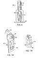
- FIG. 7Ais a perspective view of an embodiment of a clip attached to an end of a leg of the support system.
- FIG. 7Bis a side view of the clip of FIG. 7A .
- FIG. 8is a perspective view of an alternative embodiment of the support system including a rod.
- FIG. 9is a perspective view of an alternative embodiment of the rod of FIG. 8 .
- FIG. 10is a perspective view of an alternative embodiment of the support system.
- FIG. 11is a perspective view of a sprinkler support system having an alternative embodiment of a fitting.
- FIG. 12is a perspective view of an alternative embodiment of the support system.
- FIG. 13is a perspective view of an alternative embodiment of the support system
- FIG. 14is a perspective view, partially exploded, of an alternative embodiment of the central hub.
- FIG. 15is a perspective view, partially exploded, of an alternative embodiment of the central hub.
- FIG. 16is a perspective view, partially exploded, of an alternative embodiment of the central hub.
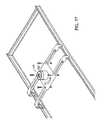
- FIG. 17is a perspective view, partially exploded, of an alternative embodiment of the central hub.
- FIG. 18is a perspective view, partially exploded, of an alternative embodiment of the central hub.
- FIG. 18Ais a perspective view of an alternative embodiment of the support system of FIG. 18 .
- FIG. 19is a perspective view, partially exploded, of an alternative embodiment of the central hub.
- a sprinkler system 2includes several support systems 30 mounted within a ceiling 4 having a ceiling frame 6 formed of an array of rectangular frame sections 8 .
- Ceiling frame 6can be a suspended ceiling for supporting a plurality of decorative panels 10 within rectangular frame sections 8 .
- sprinkler system 2is most commonly located above the ceiling frame 6 , but can also reside in a floor or in one or more walls. Support system 30 will effectively support sprinkler heads in any of these locations.
- each support system 30secures a sprinkler head 32 ( FIG. 2 ) at a predetermined position within an associated one of rectangular frame sections 8 .
- a flexible conduit 20carries a fire suppression fluid, e.g., water, from supply pipes 12 to sprinkler head 32 .
- Pipes 12can be part of a fluid delivery system dedicated to fire suppression, or can also deliver water to other functions (e.g., within the building).
- sprinkler head 32is activated and a stream of fire suppression fluid is directed into the room to extinguish the fire.
- sprinkler head 32In order to function effectively, sprinkler head 32 must be held firmly in place during operation. Due to the significant back pressure of the fluid flowing therethrough, sprinkler head 32 is subjected to tremendous side, rotational, and torsional forces, which are capable of changing the position of the sprinkler head, thereby causing the fluid to be directed away from the intended target.
- support system 30is configured to resist movement of sprinkler head 32 by distributing the forces to four spaced-apart points 34 along the periphery of one of the rectangular frame sections 8 .
- support system 30includes two legs 36 , 38 and a central hub 40 .
- Each legis attached to hub 40 and is configured to resist the forces imparted to sprinkler head 32 during its operation.
- both legs 36 , 38extend across the width of the rectangular frame section 8 from a frame side 14 to an opposite and parallel frame side 16 .
- each leg 36 , 38is formed as a channel-shaped, one-piece strut having a slot 42 extending along a substantial length of the leg.
- Central hub 40includes a plate 44 and a sleeve 46 . Plate 44 attaches at one or more points.
- Leg 36is attached on an opposite side of plate 44 than leg 38 .
- Plate 44has a width (w) defining the spacing between legs 36 , 38 .
- Plate 44can be permanently or slidably attached to legs 36 , 38 .
- a permanent attachmentenables plate 44 to firmly support sleeve 46 and sprinkler head 32 , as well as maintain a space between the two legs 36 , 38 .
- plate 44is configured to slide along the length of legs 36 , 38 to adjust the position of plate 44 and sprinkler head 32 attached thereto.
- Plate 44includes four bolts 48 , each of which extends through plate 44 and slot 42 of legs 36 , 38 .
- Plate 44is attached to each leg with two bolts 48 .
- By attaching each of bolts 48 to a nut positioned beneath legs 36 , 38plate 44 is fastened to the legs. If bolts 48 are loosened or removed, plate 44 is freely slidable along the length of legs 36 , 38 . Once plate 44 is properly positioned, bolts 48 are tightened to the nuts, fixing the plate at that location.
- Plate 44is preferably attached to legs 36 , 38 in a manner to maintain the space between the two legs, and to hold them substantially parallel to each other.
- the space between legs 36 , 38ensures that legs 36 , 38 connect to frame section 8 at four distinct points 34 , better distributing the forces on support system 30 during sprinkler head operation.
- the water pressure exiting the sprinkler head 32can reach as high as 175 psi, exerting upward and possible outward force on support system 30 . If support system 30 is not sufficiently stable these forces will disconnect it from frame section 8 .
- By using two spaced-apart legs support system 30distributes the forces to four spaced points, providing a more stable platform.
- Legs 36 , 38should be spaced-apart far enough that the four points at which the legs connect to ceiling frame section 8 give the bracket proper stability, distributing the back-pressure and preventing sprinkler head 32 from moving or rotating in any direction during sprinkler operation.
- legs 36 , 38have four clips 50 that attach to the four spaced-apart points 34 of rectangular frame 12 .
- the ends of legs 36 , 38can be punched and bent to form clip 50 .
- Clip 50includes a tongue 52 spaced from a seating frame 54 , and a gap 56 .
- Tongue 52serves as a cantilever spring that can be bent away from gap 56 to allow the frame side of frame section 8 to be positioned in the gap. Releasing tongue 52 engages the frame side between the tongue 52 and seating frame 54 .
- This type of clip 50can be especially useful when the ceiling 4 is a suspended ceiling, which typically uses a grid of T-bar to support decorative panels 10 .
- Clip 50can be easily slid or relocated on the T-bar to reposition the support system.
- Clips 50 at one end of each of legs 36 , 38attaches to frame side 14 , while clips 50 on opposite end of legs 36 , 38 attach to opposite frame side 16 .
- Clips 50can be detached from frame sides 14 , 16 and reattached at different points along frame sides 14 , 16 .
- clip 50can be slid along frame sides 14 , 16 .
- support system 30can be positioned at any point along frame section 8 , and can be moved to a different point if the need to reposition sprinkler head 32 arises. That is, when legs 36 , 38 span the width of the frame by connecting to frame sides 14 , 16 , clips 50 allow legs 36 , 38 to be slid along the length of frame sides 14 , 16 .
- clip 50is designed to slip off of decorative panel 10 in response to a predetermined amount of force. Thus, clip 50 can break away from decorative panel 10 in the event of a ceiling failure.
- Sleeve 46 of central hub 40is secured to plate 44 and is adapted to receive sprinkler head 32 .
- the height of sprinkler head 32may be adjusted within sleeve 46 by any of the commonly known attachment methods, e.g., by the loosening and tightening of a set screw. If the position of either central hub 40 on legs 36 , 38 or sprinkler head 32 in sleeve 46 is adjusted, it is preferable that the connections be securely fastened during installation to prevent any further movement during fire suppression operations.
- the mechanisms for adjusting the plate's 44 position on legs 36 , 38 and the sprinkler head's 32 positioncan be combined with the slidable clip 50 mechanisms, as described above, allowing the contractor installing the support system to position sprinkler head 32 at any point within frame section 8 .
- the ability to easily relocate or position support system 30especially when combined with flexible conduit 20 , provides installers with the maximum amount of flexibility for positioning sprinkler head 32 without additional plumbing work. This is especially advantageous in renovations or remodeling operations, where circumstances frequently require that sprinkler heads 32 be simply moved a few feet.
- flexible conduit 20delivers the fire suppression fluid from pipe 12 to sprinkler head 32 .
- Flexible conduit 20is constructed of stainless steel with a braided sleeve. Because conduit 20 is flexible numerous benefits are provided in many applications. For example, flexible conduit 20 eliminates elbows and additional pipe sections generally required to properly position sprinkler head 32 . As a result, the number of parts as well as the time and labor needed for installing the system is reduced. Flexible conduit 20 allows the contractor to easily move sprinkler drops during renovations. Further, flexible conduit 20 reduces the likelihood of leakage at joints, allows easy adjustment of sprinkler head 32 position without additional plumbing work, allows a greater latitude in positioning sprinkler head 32 to aesthetically pleasing locations, and helps reduce the possibility of damage to the sprinkler system 2 during seismic activity, fire, or renovation.
- Rigid fitting 62can be any one or more commonly known methods of connecting to pipe, including, for example, threaded, grooved, socket welded, socket glued, regular welded, pressed fit, compression fitting, or a flare fitting connections.
- an adaptorcan be used to attach fitting 62 to conduit 20 . The method selected will depend on the material used for conduit 20 .
- Rigid fitting 62can be made of any material, but the material used will generally depend on the material used for conduit 20 .
- a second end 64 of flexible conduit 20is attached to a fitting 66 , which is in turn attached to sprinkler head 32 by any of the above methods.
- fitting 66can be a rigid, substantially cylindrical tube, e.g., a reducing fitting.
- fitting 66is a swaged fitting as described in U.S. Pat. No. 5,794,853, incorporated herein by reference.
- Fitting 66can include a conduit end 70 , a sprinkler head end 72 and an inner surface 74 .
- Conduit end 70includes an external surface to receive conduit 20 .
- Sprinkler head end 72is internally threaded on inner surface 74 to receive sprinkler head 32 .
- Sprinkler head 32can be any of the sprinkler head designs commonly used in the fire protection industry. Depending on the dimensions of sprinkler head 32 and the dimensions of flexible conduit 20 an adapter (not shown) may be required to connect fitting 66 and sprinkler head 32 . The type of connection between fitting 66 and the sprinkler head 32 will depend on the material used for fitting 66 .
- sprinkler head 32includes a length of cylindrical pipe 80 having a fluid passage obstructed by a plug 82 .
- Plug 82is held in place by fusible links 84 , which are fabricated to melt within a specific temperature range, e.g., between 130 EF and 212 EF.
- Alternative methods of holding plug 82 in placeinclude a bottle of glycerin that expands when heated to break the vile.
- links 84break, plug 82 is released from pipe 80 by the pressure of the sprinkler system fluid, and the fluid is scattered over a wide area by a dispersion device 86 .
- the outer surface of pipe 80includes threads 88 for connection to fitting 66 .
- a support structurecan either fail, that is, fall down, or may be removed, such as during renovations. For example, during a fire or an earthquake all or parts of ceiling frame 6 can collapse. Similarly, a crew removing ceiling frame 6 during renovations may not always take care to separate the sprinkler system from frame section 8 before it is torn down. In addition, if it is suspected that a fire is located above a suspended ceiling, a suspended ceiling will be torn down. In many locations local codes may require that the sprinkler system continue to operate when the ceiling is torn down.
- support system 30is rigidly or permanently attached to frame section 8 , then support system 30 will fall or be removed with frame section 8 .
- the resultwill be significant damage to sprinkler system 2 , as well as damage to the building from the inevitable water leaks. Further, if, due to this damage, sprinkler system 2 fails to operate during a fire or an earthquake the building may be destroyed.
- sprinkler system 2will not be damaged or fail to operate if support system 30 includes a mechanism capable of separating the support system 30 from frame section 8 when frame section 8 fails.
- support system 30can hang from a building component.
- an auxiliary support mechanismsuch as a rod, chain, wire, or rope, attached to the building component may continue to support system 30 .
- Break away clip 90is a break away clip 90 , as shown in FIGS. 7A and 7B .
- Leg 36can be attached to frame section 8 by break away clip 90 .
- Break away clip 90is formed with a metal sheet 92 , e.g., spring steel, which has been punched and bent as described above in conjunction with FIG. 4 .
- Break away clip 90includes a tongue 94 , a gap 96 and metal sheet 92 .
- Break away clip 90is attached to leg 36 (or 38 ) at a joint 98 by a loose rivet 100 .
- a break away embodimentis especially useful when combined with the auxiliary support mechanism, which can hold the support system in place during support structure failure.
- Joint 98is constructed such that under a predetermined amount of force, clip 90 breaks free from the leg allowing support system 30 to remain held in place by the auxiliary support mechanism in the event of a support structure failure. This break away action allows the sprinkler system to continue operation during a support structure failure. Further, loose rivet 100 allows flexibility, increasing the ease of installation.
- sprinkler system 2can be protected from support structure failure by other mechanisms, including clip 50 ( FIGS. 3 and 4 ) separating from frame section 8 , clip 50 separating from legs 36 , 38 , central hub 40 separating from legs 36 , 38 , or sleeve 46 separating from central hub 40 .
- a non-break away systemcan have (as shown in FIGS. 3 and 4 ) advantages. For instance, in geographic areas that experience frequent or significant seismic activity, a non-break away system may be preferred over a break away system.
- support system 30can attach to any manner of support structure in a ceiling, wall, or floor. As described above, support system 30 can attach to a suspended ceiling. Alternatively, support system 30 can attach directly to a building structural member, such as, for example, wood joists and studs or another building component. Support system 30 can be attached to the building structural member, e.g., a concrete ceiling above a suspended ceiling by changing the type of the connector to a concrete drop in anchor. A lengthened fitting can then be used to extend the sprinkler head to the suitable location in the suspended ceiling tile.
- a building structural membersuch as, for example, wood joists and studs or another building component.
- Support system 30can be attached to the building structural member, e.g., a concrete ceiling above a suspended ceiling by changing the type of the connector to a concrete drop in anchor. A lengthened fitting can then be used to extend the sprinkler head to the suitable location in the suspended ceiling tile.
- support system 30can include a rod 110 .
- Rod 110is designed to perform two functions. First, rod 110 helps hold support system 30 in place by resisting the back pressure and twisting forces generated during sprinkler head operation. Second, in the event of support structure failure, as described above, support system 30 will break away from the support structure and hang from rod 110 , enabling support system 30 to remain in position and continue to provide fire protection.
- an upper portion 112 of rod 110is connected to a building component (not shown) such as an I-beam, pipe, concrete wall, the ceiling, or other structural support, by a connection device (not shown).
- the connection devicecan be a c-clamp, concrete drop in anchor, nail, lag screw or other connection mechanism.
- a lower portion 114 of rod 110can be attached to support system 30 , at, for example, central hub 40 , e.g., at sleeve 46 .
- Rod 110can also attach to the flexible sprinkler assemblage, described below.
- Rod 110can be attached to sleeve 46 by welding, by screwing rod 110 into a hole drilled into sleeve 46 , or by any other commonly known attachment mechanism.
- a mounting block 116can be affixed, e.g., by welding, to sleeve 46 .
- Rod 110is screwed into internal threads within mounting block 116 .
- a channelmay be located on plate 44 , and rod 110 may be located at any point on the channel. This system has the advantage of easy adjustment of the rod's length and position.
- rod 110depends on the distance between support system 30 and the building component to which rod 110 is attached. Rod 110 must be long enough to reach from the support assembly to the building component. The distance between the best location for a sprinkler head and the nearest building component will vary widely. As a result, for many buildings it can prove difficult or simply unfeasible to predetermine the length of rod needed for each support system 30 . To solve this difficulty, rods of predetermined lengths can be provided alongside a mechanism for adjusting their length. One such mechanism is to provide a threaded hole at the point rod 110 connects to either the support system 30 or to the building component. Rod 110 can be threaded through this hole in varying amounts, to increase or decrease the available length of rod 110 . In another embodiment, shown in FIG.
- rod 110can consist of an upper rod 120 , a lower rod 122 , and a turnbuckle 124 .
- Upper rod 120 and lower rod 122both have threaded ends 126 , 128 , which are threaded into matching internal threads on turnbuckle 124 .
- the turnbuckleis turned in a first direction to tighten the rod and decrease the available length, and turned in a second direction to loosen the rod and increase the available length.
- Rod 110can be constructed from numerous materials, including but not limited to stainless steel, other steels, rubbers, plastics, polymers, ferrous metals, non ferrous metals, polycarbonates, or any combination thereof.
- rod 110can be a standard steel threaded plumbing rod.
- a pair of rods 130 , 132can be used to provide additional support. Both rods can be connected to the central hub 40 , as shown in FIG. 10 , or they may be connected elsewhere, to same or different locations. Similarly rods 130 , 132 may be connected to the same or to different building components by the same or different connection device. Alternatively, a support 134 can be attached to a building component 136 , e.g., by a c-clamp. The two rods 130 , 132 can be attached to support 134 and extend to support system 30 .
- a rodalternatives to a rod include a chain, wire or rope, all of which can be attached to support system 30 . These devices will similarly prevent support system 30 from falling during support structure failure. Further, in locations that experience frequent seismic events, a rod will transmit any shocks or vibrations directly from the building component to the support system. The more flexible devices will cushion the vibrations.
- fitting 66can be used with support system 30 .
- inner surface 74 of fitting 66can be any shape so long as water or fluid is conveyed to sprinkler head 32 .
- Inner surface 74is funnel shaped in FIG. 5 .
- inner surface 74may be, for example, cylindrical, or frustoconical.
- fitting 66can be lengthened and include a 90 E bend 140 , and a rigid pipe 142 . Any angle can be used for bend 140 , depending on system requirements.
- Various methods of connecting fitting 66 to sprinkler head 32 and conduit 20can also be used with support system 30 , including groove connections, press fittings, compression fittings, socket fittings, and flare fittings.
- the groovescan be on the inner or outer surfaces of the fitting.
- the conduit end and sprinkler head end groovescan be on the same surface, e.g., the outer surface, or they can be on different surfaces.
- Fitting 66can be formed from stainless steel, other steels, rubbers, plastics, polymers, ferrous metals, non ferrous metals, polycarbonates, or any combination thereof. Its configuration depends on the type of conduit, the type of sprinkler head, the method by which the conduit and sprinkler heads are attached to the fitting, and the materials used.
- legs 36 , 38can extend between either pairs of opposing frame sides. That is, legs 36 , 38 can span between frame sides 14 and 16 , or legs 36 , 38 can extend between the other two frame sides.
- legs 36 , 38can be parallel to the plane of the ceiling 4 .
- part or all of the legsmay have an upward incline from the connection to frame section 8 towards central hub 40 , forming a inverted V shape.
- Numerous other leg designsare within the scope of the invention and claims.
- legs 36 , 38can consist of a combination of parallel portions and angled portions.
- center portions of legs 36 , 38can be parallel to each other, and outer portions of both legs can be angled away from each other.
- This designhas the advantage of increasing the distance between the four distinct points 34 at which ends 50 of legs 36 , 38 attach to frame section 8 , better distributing the forces on support system 30 during sprinkler head operation.
- central hub 40remains relatively small and compact because the distance between the center portions of legs 36 , 38 is smaller than the distance between the outer portions.
- each legcan be U shaped and connect to the same frame side at two locations.
- leg 150attaches to frame side 14 twice, while leg 152 attaches to the opposite frame side 16 .
- Support system 30can use three or more legs to provide additional support to sprinkler head 32 . As shown in FIG. 13 , support system 30 can use four legs, for example. A third leg 154 and a fourth leg 156 can be perpendicular to legs 36 , 38 , as shown, or can take any other orientation.
- Legs 36 , 38may be constructed of nearly any material, including, but not limited, to stainless steel, other steels, rubbers, plastics, polymers, ferrous metals, non ferrous metals, polycarbonates, or any combination thereof.
- the materials used for the support system and the flexible sprinkler assemblageare non-burnable.
- fastening devicesfor securing legs 36 , 38 to frame section 8 .
- the specific fastening devicewill depend on what building component the support system 30 must be attached to, and include all known attachment methods known in the art.
- Fastening devicesinclude nails, other clips, bolts, screws, slotted connections, tab and slot connections, and other connection styles known in the art.
- the members of suspended ceiling support structuresgenerally include slots in the frame sections to accommodate other cross members of the support structure.
- the fastening devicecan be one or more tabs attached to one or more legs (or to the plate, for example) that are inserted into the slot and bent over to secure the tabs.
- Sprinkler head 32 , fitting 66 and conduit 20can be pre-connected, either by the contractor while on the ground, or by the manufacturer at the factory, and provided as a flexible sprinkler assemblage.
- a flexible sprinkler assemblagehas the added advantage that the connections between conduit 20 , fitting 66 , and sprinkler head 32 can be tested for leaks before installation.
- the orientation of the sprinkler headscan be uniform, with the dispersion devices rotated to a uniform position.
- a markcan be added to the flexible conduit before the sprinkler head is fastened within the support system. The mark indicates the relative orientation of the dispersion device. During installation the mark is positioned relative to the central hub, which can include a corresponding mark. The mark can be made during installation, or it can be provided as part of the flexible sprinkler assemblage or the support system.
- Plate 44 and sleeve 46can be rigidly connected by any known connection method, e.g., by welding. However, if plate 44 and sleeve 46 are permanently and rigidly connected, the contractor may need to thread sprinkler head 32 and fitting 66 through sleeve 46 while the sleeve is connected to the more bulky support system 30 . Further, if the contractor connects the conduit to the pipes before the sprinkler head is threaded through sleeve 46 , then sleeve 46 should be formed wide enough to accommodate the sprinkler head, the fitting, and an escutcheon. The escutcheon is a decorative plate that hides the hole cut in the decorative panel to accommodate the sprinkler head.
- FIG. 14demonstrates one embodiment of a removable sleeve 160 .
- This embodimentallows the same model of a plate 162 and support assembly 30 to be capable of supporting widely different sizes and shapes of sprinkler heads 32 .
- Various connection mechanismsare contemplated for connecting removable sleeve 160 to plate 162 .
- Sleeve 160can simply be bolted or screwed on top of plate 162 .
- a channel 163may be provided within plate 162 , with sleeve 160 slid within the channel.
- a two part central hubcan also be constructed by splitting plate 162 and sleeve 160 into two plate sections, 164 and 166 , and two sleeve sections, 168 and 170 .
- a hinge(not shown) connects the two plate sections, allowing the central hub to swing open to receive sprinkler head 32 , and then to swing shut to hold the sprinkler head 32 in place.
- just plate 162may be split into two sections and hinged. The relative orientation of the hinge can be parallel to the legs or transverse to them.
- sleeve 160can comprise a telescoping sleeve.
- sleeve 160is rotated in one direction to open its center. While open, sprinkler head 32 is inserted and positioned to the proper height. Once sprinkler head 32 is in place sleeve 160 is rotated in the opposite direction to close it and fasten sprinkler head 32 in place.
- plate 44can simply be a narrow strip 190 between legs 36 , 38 , with a ring 192 for a sleeve.
- plate 44may support more than one sleeve 46 , allowing multiple sprinkler heads 32 , or simply offering the installer the choice of which sleeve to place the sprinkler head 32 into.
- sleeve 46is formed as strip 200 with a hole in its center for the flexible sprinkler assemblage.
- Strip 200can be two wings that are attached, e.g., welded, to the flexible sprinkler assemblage.
- Plate 162can be formed to include a flat section 180 and two bent sections 182 , 184 .
- the bent sections 182 , 184can be bent at approximately a 90E angle to the flat section, and are thus designed to slide over and attach to legs 36 , 38 .
- the flexible hose used for conduit 20can be constructed out of any material that is flexible in nature, including, but not limited to, stainless steel, stainless steel with a braided sleeve, other steels, rubbers, plastics, polymers, ferrous metals, non ferrous metals, polycarbonates, or any combination thereof.
- conduit 20can be any type of tubing, including plumbing pipe or PVC pipe.
- plate 44can also be formed with an integral clip to attach to legs 36 , 38 , or simply be designed to fold around or to snap on to legs 36 , 38 . Either of these embodiments can provide a break away mechanism in the event of support structure failure.
- the order of steps the contractor follows during installationcan be varied.
- the contractorcan first attach one or more of clips 50 on the ends of legs 36 , 38 to ceiling frame section 8 at the approximate location desired.
- Support assembly 30can be moved along frame section 8 to adjust the support assembly's 30 position.
- the position of central hub 40 on legs 36 , 38can also be adjusted to fine tune the position of sprinkler head 32 in the plane of the ceiling, wall or floor it is being installed in. Adjustments on these two axis allow the contractor to place sprinkler head 32 in the best position for safety or aesthetic reasons. If rod 110 is to be used it can be installed next.
- sprinkler head 32can be positioned within sleeve 46 , adjusting the sprinkler head's 32 position on the axis transverse to the plane of the ceiling, wall, or floor. Pipe 12 , conduit 20 , fitting 66 , and sprinkler head 32 must all be connected and checked for leaks.
- support system 30provides the contractor with maximum flexibility, allowing sprinkler head's 32 position to be adjusted in three dimensions.
Landscapes
- Health & Medical Sciences (AREA)
- Public Health (AREA)
- Business, Economics & Management (AREA)
- Emergency Management (AREA)
- Fire-Extinguishing By Fire Departments, And Fire-Extinguishing Equipment And Control Thereof (AREA)
Abstract
Description
Claims (61)
Priority Applications (5)
| Application Number | Priority Date | Filing Date | Title |
|---|---|---|---|
| US10/807,817US7032680B2 (en) | 1999-01-08 | 2004-03-24 | Fire protection sprinkler head support |
| US11/352,449US20070039743A1 (en) | 1999-01-08 | 2006-02-09 | Fire protection sprinkler head support |
| US11/566,317US20070095548A1 (en) | 1999-01-08 | 2006-12-04 | Fire Protection Sprinkler Head Support |
| US11/862,852US20080066932A1 (en) | 1999-01-08 | 2007-09-27 | Fire protection sprinkler head support |
| US12/212,009US20090008104A1 (en) | 1999-01-08 | 2008-09-17 | Fire protection sprinkler head support |
Applications Claiming Priority (3)
| Application Number | Priority Date | Filing Date | Title |
|---|---|---|---|
| US09/227,525US6488097B1 (en) | 1999-01-08 | 1999-01-08 | Fire protection sprinkler head support |
| US10/294,886US6752218B2 (en) | 1999-01-08 | 2002-11-14 | Fire protection sprinkler head support |
| US10/807,817US7032680B2 (en) | 1999-01-08 | 2004-03-24 | Fire protection sprinkler head support |
Related Parent Applications (1)
| Application Number | Title | Priority Date | Filing Date |
|---|---|---|---|
| US10/294,886ContinuationUS6752218B2 (en) | 1999-01-08 | 2002-11-14 | Fire protection sprinkler head support |
Related Child Applications (2)
| Application Number | Title | Priority Date | Filing Date |
|---|---|---|---|
| US11/352,449ContinuationUS20070039743A1 (en) | 1999-01-08 | 2006-02-09 | Fire protection sprinkler head support |
| US11/566,317ContinuationUS20070095548A1 (en) | 1999-01-08 | 2006-12-04 | Fire Protection Sprinkler Head Support |
Publications (2)
| Publication Number | Publication Date |
|---|---|
| US20040177976A1 US20040177976A1 (en) | 2004-09-16 |
| US7032680B2true US7032680B2 (en) | 2006-04-25 |
Family
ID=22853442
Family Applications (7)
| Application Number | Title | Priority Date | Filing Date |
|---|---|---|---|
| US09/227,525Expired - LifetimeUS6488097B1 (en) | 1999-01-08 | 1999-01-08 | Fire protection sprinkler head support |
| US10/294,886Expired - LifetimeUS6752218B2 (en) | 1999-01-08 | 2002-11-14 | Fire protection sprinkler head support |
| US10/807,817Expired - LifetimeUS7032680B2 (en) | 1999-01-08 | 2004-03-24 | Fire protection sprinkler head support |
| US11/352,449AbandonedUS20070039743A1 (en) | 1999-01-08 | 2006-02-09 | Fire protection sprinkler head support |
| US11/566,317AbandonedUS20070095548A1 (en) | 1999-01-08 | 2006-12-04 | Fire Protection Sprinkler Head Support |
| US11/862,852AbandonedUS20080066932A1 (en) | 1999-01-08 | 2007-09-27 | Fire protection sprinkler head support |
| US12/212,009AbandonedUS20090008104A1 (en) | 1999-01-08 | 2008-09-17 | Fire protection sprinkler head support |
Family Applications Before (2)
| Application Number | Title | Priority Date | Filing Date |
|---|---|---|---|
| US09/227,525Expired - LifetimeUS6488097B1 (en) | 1999-01-08 | 1999-01-08 | Fire protection sprinkler head support |
| US10/294,886Expired - LifetimeUS6752218B2 (en) | 1999-01-08 | 2002-11-14 | Fire protection sprinkler head support |
Family Applications After (4)
| Application Number | Title | Priority Date | Filing Date |
|---|---|---|---|
| US11/352,449AbandonedUS20070039743A1 (en) | 1999-01-08 | 2006-02-09 | Fire protection sprinkler head support |
| US11/566,317AbandonedUS20070095548A1 (en) | 1999-01-08 | 2006-12-04 | Fire Protection Sprinkler Head Support |
| US11/862,852AbandonedUS20080066932A1 (en) | 1999-01-08 | 2007-09-27 | Fire protection sprinkler head support |
| US12/212,009AbandonedUS20090008104A1 (en) | 1999-01-08 | 2008-09-17 | Fire protection sprinkler head support |
Country Status (1)
| Country | Link |
|---|---|
| US (7) | US6488097B1 (en) |
Cited By (17)
| Publication number | Priority date | Publication date | Assignee | Title |
|---|---|---|---|---|
| US20070290101A1 (en)* | 2006-06-16 | 2007-12-20 | Witzenmann Gmbh | Sprinkler Mount |
| US20080230238A1 (en)* | 2007-03-22 | 2008-09-25 | The Viking Corporation | Mounting Coupling For Sprinkler Support System |
| US20090045301A1 (en)* | 2007-08-13 | 2009-02-19 | C&S Manufacturing Corporation | Rail mount for flexible conduit |
| US20090184226A1 (en)* | 2008-01-17 | 2009-07-23 | Target Brands, Inc. | Ceiling grid spanner |
| US20110215566A1 (en)* | 2009-09-11 | 2011-09-08 | Victaulic Company | Flexible Assembly for Sprinklers |
| US8272615B2 (en) | 2010-05-20 | 2012-09-25 | Flexhead Industries, Inc. | Hub with locking mechanism |
| US20130081250A1 (en)* | 2011-10-03 | 2013-04-04 | The Wanda Group | Sprinkler fitting attachment device |
| US8413734B2 (en) | 2010-10-26 | 2013-04-09 | Flexhead Industries, Inc. | Clamp for sprinkler support assembly |
| US20130284078A1 (en)* | 2012-04-25 | 2013-10-31 | Domenick Francis De Rose | Suspension of a storage framework from a beam |
| US8740158B2 (en) | 2010-06-25 | 2014-06-03 | Flexhead Industries, Inc. | Hat channel adaptor for sprinkler support assembly |
| US8887822B2 (en) | 2012-06-01 | 2014-11-18 | Reliable Automatic Sprinkler Co., Inc. | Flexible dry sprinklers |
| US9004422B2 (en) | 2011-11-02 | 2015-04-14 | The Viking Corporation | Fire protection sprinkler support system |
| US9004421B2 (en) | 2011-11-02 | 2015-04-14 | The Viking Corporation | Fire protection sprinkler support system |
| US9889327B2 (en) | 2014-06-27 | 2018-02-13 | Flexhead Industries, Inc. | Adjustable bracket and hub for flexible hose support |
| US10143872B2 (en) | 2011-05-27 | 2018-12-04 | Victaulic Company | Flexible dry sprinkler |
| US10173088B2 (en) | 2014-05-28 | 2019-01-08 | The Reliable Automatic Sprinkler Co., Inc. | Bracket for installation of a fire protection sprinkler |
| US10561872B2 (en) | 2016-11-17 | 2020-02-18 | Anvil International, Llc | Fire sprinkler assembly including adjustable drop |
Families Citing this family (35)
| Publication number | Priority date | Publication date | Assignee | Title |
|---|---|---|---|---|
| US6488097B1 (en)* | 1999-01-08 | 2002-12-03 | Pnm, Inc. | Fire protection sprinkler head support |
| JP3818968B2 (en)* | 2003-01-21 | 2006-09-06 | ティーオーエー株式会社 | Auxiliary mounting device for ceiling-mounted speaker system |
| US7568313B1 (en)* | 2003-07-03 | 2009-08-04 | Matley William T | Suspended ceiling projector mount apparatus |
| US8555571B2 (en)* | 2004-01-09 | 2013-10-15 | Vkr Holding A/S | Skylight with displacement absorber and interlocking telescoping tubes |
| CA2518294C (en)* | 2004-09-07 | 2009-06-23 | Chicago Metallic Corporation | Seismic perimeter clip for suspended ceiling grid |
| US7520538B2 (en)* | 2005-01-14 | 2009-04-21 | Mcgushion Kevin David | Orbital tube welding purge adaptor |
| US7172221B1 (en) | 2005-02-11 | 2007-02-06 | Ferrara Joseph F | Pipe stabilizing system |
| US7255315B2 (en)* | 2005-02-25 | 2007-08-14 | Kofulso Co., Ltd. | Mounting structure for sprinklers |
| US7950614B1 (en)* | 2005-04-22 | 2011-05-31 | Strobridge Stephen A | Medical equipment overhead mounting structure |
| US7269908B1 (en)* | 2005-04-28 | 2007-09-18 | Ryan Alvar | Tool for projecting a visually perceptible plumb line from a proposed location of a fire sprinkler head on a suspended ceiling and method of using |
| US20080016811A1 (en)* | 2006-07-19 | 2008-01-24 | Johnston Wayne R | Fire protection mounting system and method for mounting |
| US20080148665A1 (en)* | 2006-12-21 | 2008-06-26 | Yonash Richard F | Ceiling tiles made of rigid pvc |
| US7699117B2 (en)* | 2007-05-09 | 2010-04-20 | The Wanda Group | Fire protection sprinkler system and related apparatus |
| KR101014385B1 (en)* | 2010-09-14 | 2011-02-15 | 임영순 | Mounting Clamp for Fire Sprinkler |
| MX344119B (en) | 2011-05-27 | 2016-12-06 | Victaulic Co Of America | X-brace valve and flexible connection for fire sprinklers. |
| US9511248B2 (en)* | 2011-08-10 | 2016-12-06 | Victaulic Company | Sprinkler system and installation |
| USD674123S1 (en) | 2011-10-25 | 2013-01-08 | Empire West, Inc. | Ceiling tile |
| CA2802728A1 (en) | 2012-02-03 | 2013-08-03 | The Reliable Automatic Sprinkler Co., Inc. | Flexible dry sprinklers |
| US10449402B2 (en) | 2012-12-20 | 2019-10-22 | Victaulic Company | Dry sprinkler |
| US9345918B2 (en) | 2012-12-20 | 2016-05-24 | Victaulic Company | Dry sprinkler |
| US9415250B2 (en) | 2012-12-20 | 2016-08-16 | Victaulic Company | Dry sprinkler |
| US20140231103A1 (en)* | 2013-02-15 | 2014-08-21 | Victaulic Company | Identification Sleeve for Flexible Conduit |
| US9849320B2 (en)* | 2013-03-13 | 2017-12-26 | Tyco Fire Products Lp | Fire protection sprinkler assembly |
| US9605687B1 (en)* | 2013-05-15 | 2017-03-28 | Chien Luen Industries Co., Ltd., Inc. | Automatic locking downward coupler for ceiling fan |
| US9302131B2 (en)* | 2013-08-15 | 2016-04-05 | Ewing Johnson | Hold down bracket for fire valve |
| US10173874B2 (en)* | 2014-07-16 | 2019-01-08 | Dell Products, L.P. | Integrated rack lifting apparatus |
| US10859190B2 (en) | 2016-05-16 | 2020-12-08 | Victaulic Company | Sprung coupling |
| US10527203B2 (en) | 2016-10-12 | 2020-01-07 | Anvil International, Llc | Snap to grid bracket for a sprinkler support assembly |
| US10610716B2 (en)* | 2017-06-08 | 2020-04-07 | Anvil International, Llc | Sprinkler drop bracket for intersecting downlight |
| US10010731B1 (en)* | 2017-06-08 | 2018-07-03 | Anvil International, Llc | Sprinkler drop bracket for intersecting downlight |
| US10981189B2 (en)* | 2017-07-07 | 2021-04-20 | Anvil International, Llc | Hanging connector for flexible sprinkler conduit |
| USD854915S1 (en) | 2017-11-08 | 2019-07-30 | Anvil International, Llc | Conduit hanger adapter |
| IL280860B2 (en) | 2018-08-23 | 2024-07-01 | Victaulic Co Of America | Dry sprinkler assembly |
| US12239866B2 (en)* | 2019-08-02 | 2025-03-04 | Tyco Fire Products Lp | Sprinkler box for embedded sprinkler pipe system |
| US20220025672A1 (en)* | 2020-07-23 | 2022-01-27 | Ex Nihilo, LLC dba Jumping Targets | Base for vertical posts |
Citations (72)
| Publication number | Priority date | Publication date | Assignee | Title |
|---|---|---|---|---|
| US1056759A (en) | 1912-02-19 | 1913-03-18 | Alice L Hennessy | Switch-box and support. |
| US1156885A (en) | 1911-12-12 | 1915-10-19 | New England Electric Company | Outlet-box bracket. |
| US2375513A (en) | 1943-09-30 | 1945-05-08 | William F Bach | Pipe hanger system |
| US3341909A (en) | 1965-09-01 | 1967-09-19 | Spring Steel Fasteners Inc | Clamp |
| US3529671A (en) | 1968-10-22 | 1970-09-22 | Charles Adams Jr | Adjustable drop nipple for sprinklers below hung ceilings |
| US3556452A (en) | 1969-06-02 | 1971-01-19 | William W Ramsey | Lighting fixture clamping device |
| US3558091A (en) | 1968-11-18 | 1971-01-26 | Bundy Corp | Channel-beam clamp |
| US3597889A (en) | 1969-10-08 | 1971-08-10 | Antonio Lo Nigro | Junction box suspension unit for suspended ceilings |
| US3608857A (en) | 1969-12-11 | 1971-09-28 | Richard H Hibbeler | Channel clip for t-bars |
| US3612461A (en) | 1970-04-20 | 1971-10-12 | Minerallac Electric Co | Light fixture supporting clip |
| US3652780A (en) | 1970-10-30 | 1972-03-28 | Dare Products Inc | Reversibly mountable insulator |
| US3675952A (en) | 1970-07-24 | 1972-07-11 | Grinnell Corp | Adjustable drop nipple for pendent sprinkler |
| US3685235A (en) | 1970-09-21 | 1972-08-22 | Bajer Ind Inc | Suspended ceiling system including a grid network |
| US3703307A (en) | 1970-10-16 | 1972-11-21 | Integrated Ceilings Inc | Connector structure for suspended ceilings and the like |
| US3797789A (en) | 1972-03-22 | 1974-03-19 | Armstrong Cork Co | Support bar for suspended ceiling light fixture |
| US3848385A (en) | 1970-06-12 | 1974-11-19 | Nat Ceiling Corp | Modular ceiling construction |
| US3874035A (en) | 1974-06-26 | 1975-04-01 | Fastway Fasteners | Hanger clip |
| US4041657A (en) | 1975-09-18 | 1977-08-16 | Fastway Fasteners, Inc. | Fixture support for grid type ceiling |
| US4122762A (en) | 1977-03-07 | 1978-10-31 | Williams Arthur C | Air-slot spacer clip |
| US4135692A (en) | 1978-01-05 | 1979-01-23 | Ferguson William J | Hanger device |
| US4149693A (en) | 1977-12-02 | 1979-04-17 | Lonigro Antonio | Fixture support with twisted central portion |
| US4408428A (en) | 1982-09-28 | 1983-10-11 | United States Gypsum Company | Suspended panel ceiling having impact absorbent panel retaining clip assemblies |
| US4484634A (en) | 1983-01-10 | 1984-11-27 | Aeroquip Corporation | Flexible fire protection system |
| US4544119A (en) | 1983-11-01 | 1985-10-01 | Kellett Roger N | Bar joist supported suspension clips |
| US4717099A (en) | 1986-05-15 | 1988-01-05 | Hubbard George R | Fire sprinkler alignment bracket |
| US4723749A (en) | 1986-05-19 | 1988-02-09 | Erico International Corporation | Channel clip |
| US4785887A (en) | 1987-03-03 | 1988-11-22 | Lifesaving Systems, Inc. | Adjustable fire sprinkler head support system |
| US4834186A (en) | 1987-10-19 | 1989-05-30 | Ballard Estus E | Sprinkler head mounting system |
| JPH0210A (en) | 1987-10-12 | 1990-01-05 | Seiko Epson Corp | Driving method for electrooptical device |
| JPH0296160A (en) | 1988-05-03 | 1990-04-06 | Flex Prod Inc | High-resolution hot-stamped transfer foil article, to which image is formed previously, and method |
| DE3913638A1 (en) | 1989-04-26 | 1990-10-31 | Licentia Gmbh | Forming speech pattern for speech-controlled dishwashers etc. - involves acoustic-visual repetition of code word spoken by operator |
| KR910002450A (en) | 1989-07-26 | 1991-02-25 | 게리 디.스트리트 | Pharmaceutical composition for the treatment of diabetes |
| US5018586A (en) | 1990-01-26 | 1991-05-28 | Dennis Cawley | Fire suppression system for a decorative tree |
| JPH045971A (en) | 1990-04-23 | 1992-01-09 | Isuzu Kogyo Kk | Constructing method for sprinkler head fitting piping and sprinkler head fitting wiring structure |
| US5085393A (en) | 1990-07-24 | 1992-02-04 | Ryan Patrick V | Hanger assembly method and apparatus |
| US5127479A (en) | 1990-12-31 | 1992-07-07 | 21St Century International Fire Equipment Services Corporation | Fire extinguishing system for cookstoves and ranges |
| JPH04361759A (en) | 1991-06-10 | 1992-12-15 | Takenaka Komuten Co Ltd | Method for installing sprinkler head |
| JPH0560283A (en) | 1991-08-27 | 1993-03-09 | Matsushita Electric Works Ltd | Piping part for sprinkler |
| KR930004992A (en) | 1991-08-20 | 1993-03-23 | 오오가 노리오 | Audio signal playback device |
| JPH0584321A (en) | 1991-08-23 | 1993-04-06 | Shimizu Corp | Connection structure of sprinkler head and piping |
| JPH05137810A (en) | 1991-11-18 | 1993-06-01 | Nishihara Eisei Kogyosho Oosakaten:Kk | Unwinding tube for sprinkler |
| JPH05309146A (en) | 1992-05-07 | 1993-11-22 | Benkan Corp | Sprinkler head mounting piping construction method and sprinkler head mounting piping structure |
| JPH05329223A (en) | 1992-05-29 | 1993-12-14 | Takenaka Komuten Co Ltd | Sprinkler fire extinguishing equipment |
| JPH06125999A (en) | 1992-10-16 | 1994-05-10 | Bosai Kikaku:Kk | Extinguishing sprinkler piping structure |
| KR940009689A (en) | 1992-10-06 | 1994-05-20 | 알. 헤이스팅즈 캘빈 | Flow rate measuring device |
| US5316254A (en) | 1992-05-14 | 1994-05-31 | Mccartha Robert D | Junction box support for suspended ceilings |
| KR940019364A (en) | 1993-02-02 | 1994-09-14 | 데루키요 기타자와 | Waste disposal equipment |
| KR940023229A (en) | 1993-03-01 | 1994-10-22 | 로버트 디. 쉐드 | Automatic display device of auxiliary video information during audio muting |
| US5396959A (en) | 1993-09-20 | 1995-03-14 | Pnm, Inc. | Sprinkler system |
| JPH0796050A (en) | 1992-10-16 | 1995-04-11 | Bosai Kikaku:Kk | Sprinkler piping and installation method of sprinkler piping |
| US5516068A (en) | 1992-07-31 | 1996-05-14 | Rice; Frank | Device support bracket |
| US5564505A (en) | 1994-04-12 | 1996-10-15 | Etablissements Moliere Sa | Sprinkler mounted to pivotable conduit |
| US5570745A (en) | 1995-05-31 | 1996-11-05 | Pnm, Inc. | Relocatable sprinkler assemblage |
| US5595363A (en) | 1995-09-18 | 1997-01-21 | De Leebeeck; Marcel | Plastic pipe beam support |
| US5609212A (en) | 1990-05-03 | 1997-03-11 | Agf Manufacturing, Inc. | Adjustable sprinkler head positioning assembly |
| US5619263A (en) | 1995-03-21 | 1997-04-08 | Erico International Corporation | Box hanger and method |
| US5667181A (en) | 1994-04-18 | 1997-09-16 | Erico International Corporation | Hanger |
| US5667018A (en) | 1996-01-02 | 1997-09-16 | Fmc Corporation | Fire control foam distribution system for use in distributing foam beneath a passenger boarding bridge |
| US5699641A (en) | 1996-02-23 | 1997-12-23 | Usg Interiors, Inc. | Suspension ceiling with integrated openings |
| JPH1043325A (en) | 1997-04-28 | 1998-02-17 | Nohmi Bosai Ltd | Sprinkler extinguishing equipment |
| KR0118091Y1 (en) | 1994-11-09 | 1998-08-01 | 김형수 | Flexible joint for sprinkler |
| US5794853A (en) | 1996-08-06 | 1998-08-18 | Perkins; Lloyd | Institutional sprinkler head nipple |
| US5842526A (en) | 1995-09-26 | 1998-12-01 | Archer; Robert C. | Sprinkler head mounting system |
| US5845886A (en) | 1996-07-26 | 1998-12-08 | Mccormick; Henry | Adjustable ceiling fan support assembly |
| KR0133732Y1 (en) | 1994-06-29 | 1999-05-01 | 이대원 | Auto Iris Control |
| US6260810B1 (en) | 1999-08-16 | 2001-07-17 | Dong-A Flexible Metal Tubes Co., Ltd. | Sprinkler mounting device |
| US6341466B1 (en) | 2000-01-19 | 2002-01-29 | Cooper Technologies Company | Clip for securing an elongate member to a T-bar of a ceiling grid |
| US6345800B1 (en) | 1998-07-27 | 2002-02-12 | Nsi Enterprises, Inc. | Universal load-bearing hanger bracket and method for hanging a lighting fixture below a grid ceiling system at on-grid or off-grid locations |
| US6488097B1 (en) | 1999-01-08 | 2002-12-03 | Pnm, Inc. | Fire protection sprinkler head support |
| US20030029983A1 (en) | 1999-05-05 | 2003-02-13 | Thomas & Betts International, Inc. | Bar hanger and mounting clip assembly |
| US6554231B2 (en) | 1999-08-16 | 2003-04-29 | Dong-A Flexible Metal Tubes Co., Ltd. | Sprinkler mounting device and method |
| US6811130B1 (en) | 2003-12-10 | 2004-11-02 | Kofulso Co., Ltd. | Mounting structure for sprinklers |
Family Cites Families (1)
| Publication number | Priority date | Publication date | Assignee | Title |
|---|---|---|---|---|
| FR2624862B1 (en) | 1987-12-18 | 1990-06-08 | Oris Ind | RARE EARTH CRYPTATES, PROCESSES FOR OBTAINING SYNTHESIS INTERMEDIATES, AND APPLICATION AS FLUORESCENT MARKERS |
- 1999
- 1999-01-08USUS09/227,525patent/US6488097B1/ennot_activeExpired - Lifetime
- 2002
- 2002-11-14USUS10/294,886patent/US6752218B2/ennot_activeExpired - Lifetime
- 2004
- 2004-03-24USUS10/807,817patent/US7032680B2/ennot_activeExpired - Lifetime
- 2006
- 2006-02-09USUS11/352,449patent/US20070039743A1/ennot_activeAbandoned
- 2006-12-04USUS11/566,317patent/US20070095548A1/ennot_activeAbandoned
- 2007
- 2007-09-27USUS11/862,852patent/US20080066932A1/ennot_activeAbandoned
- 2008
- 2008-09-17USUS12/212,009patent/US20090008104A1/ennot_activeAbandoned
Patent Citations (74)
| Publication number | Priority date | Publication date | Assignee | Title |
|---|---|---|---|---|
| US1156885A (en) | 1911-12-12 | 1915-10-19 | New England Electric Company | Outlet-box bracket. |
| US1056759A (en) | 1912-02-19 | 1913-03-18 | Alice L Hennessy | Switch-box and support. |
| US2375513A (en) | 1943-09-30 | 1945-05-08 | William F Bach | Pipe hanger system |
| US3341909A (en) | 1965-09-01 | 1967-09-19 | Spring Steel Fasteners Inc | Clamp |
| US3529671A (en) | 1968-10-22 | 1970-09-22 | Charles Adams Jr | Adjustable drop nipple for sprinklers below hung ceilings |
| US3558091A (en) | 1968-11-18 | 1971-01-26 | Bundy Corp | Channel-beam clamp |
| US3556452A (en) | 1969-06-02 | 1971-01-19 | William W Ramsey | Lighting fixture clamping device |
| US3597889A (en) | 1969-10-08 | 1971-08-10 | Antonio Lo Nigro | Junction box suspension unit for suspended ceilings |
| US3608857A (en) | 1969-12-11 | 1971-09-28 | Richard H Hibbeler | Channel clip for t-bars |
| US3612461A (en) | 1970-04-20 | 1971-10-12 | Minerallac Electric Co | Light fixture supporting clip |
| US3848385A (en) | 1970-06-12 | 1974-11-19 | Nat Ceiling Corp | Modular ceiling construction |
| US3675952A (en) | 1970-07-24 | 1972-07-11 | Grinnell Corp | Adjustable drop nipple for pendent sprinkler |
| US3685235A (en) | 1970-09-21 | 1972-08-22 | Bajer Ind Inc | Suspended ceiling system including a grid network |
| US3703307A (en) | 1970-10-16 | 1972-11-21 | Integrated Ceilings Inc | Connector structure for suspended ceilings and the like |
| US3652780A (en) | 1970-10-30 | 1972-03-28 | Dare Products Inc | Reversibly mountable insulator |
| US3797789A (en) | 1972-03-22 | 1974-03-19 | Armstrong Cork Co | Support bar for suspended ceiling light fixture |
| US3874035A (en) | 1974-06-26 | 1975-04-01 | Fastway Fasteners | Hanger clip |
| US4041657A (en) | 1975-09-18 | 1977-08-16 | Fastway Fasteners, Inc. | Fixture support for grid type ceiling |
| US4122762A (en) | 1977-03-07 | 1978-10-31 | Williams Arthur C | Air-slot spacer clip |
| US4149693A (en) | 1977-12-02 | 1979-04-17 | Lonigro Antonio | Fixture support with twisted central portion |
| US4135692A (en) | 1978-01-05 | 1979-01-23 | Ferguson William J | Hanger device |
| US4408428A (en) | 1982-09-28 | 1983-10-11 | United States Gypsum Company | Suspended panel ceiling having impact absorbent panel retaining clip assemblies |
| US4484634A (en) | 1983-01-10 | 1984-11-27 | Aeroquip Corporation | Flexible fire protection system |
| US4544119A (en) | 1983-11-01 | 1985-10-01 | Kellett Roger N | Bar joist supported suspension clips |
| US4717099A (en) | 1986-05-15 | 1988-01-05 | Hubbard George R | Fire sprinkler alignment bracket |
| US4723749A (en) | 1986-05-19 | 1988-02-09 | Erico International Corporation | Channel clip |
| US4785887A (en) | 1987-03-03 | 1988-11-22 | Lifesaving Systems, Inc. | Adjustable fire sprinkler head support system |
| JPH0210A (en) | 1987-10-12 | 1990-01-05 | Seiko Epson Corp | Driving method for electrooptical device |
| US4834186A (en) | 1987-10-19 | 1989-05-30 | Ballard Estus E | Sprinkler head mounting system |
| JPH0296160A (en) | 1988-05-03 | 1990-04-06 | Flex Prod Inc | High-resolution hot-stamped transfer foil article, to which image is formed previously, and method |
| DE3913638A1 (en) | 1989-04-26 | 1990-10-31 | Licentia Gmbh | Forming speech pattern for speech-controlled dishwashers etc. - involves acoustic-visual repetition of code word spoken by operator |
| KR910002450A (en) | 1989-07-26 | 1991-02-25 | 게리 디.스트리트 | Pharmaceutical composition for the treatment of diabetes |
| US5018586A (en) | 1990-01-26 | 1991-05-28 | Dennis Cawley | Fire suppression system for a decorative tree |
| JPH045971A (en) | 1990-04-23 | 1992-01-09 | Isuzu Kogyo Kk | Constructing method for sprinkler head fitting piping and sprinkler head fitting wiring structure |
| US5327976A (en) | 1990-04-23 | 1994-07-12 | Takamasa Hattori | Method of installing pipes for sprinkler head mounting, and sprinkler-head mounting piping arrangement |
| US5609212A (en) | 1990-05-03 | 1997-03-11 | Agf Manufacturing, Inc. | Adjustable sprinkler head positioning assembly |
| US5085393A (en) | 1990-07-24 | 1992-02-04 | Ryan Patrick V | Hanger assembly method and apparatus |
| US5127479A (en) | 1990-12-31 | 1992-07-07 | 21St Century International Fire Equipment Services Corporation | Fire extinguishing system for cookstoves and ranges |
| JPH04361759A (en) | 1991-06-10 | 1992-12-15 | Takenaka Komuten Co Ltd | Method for installing sprinkler head |
| KR930004992A (en) | 1991-08-20 | 1993-03-23 | 오오가 노리오 | Audio signal playback device |
| JPH0584321A (en) | 1991-08-23 | 1993-04-06 | Shimizu Corp | Connection structure of sprinkler head and piping |
| JPH0560283A (en) | 1991-08-27 | 1993-03-09 | Matsushita Electric Works Ltd | Piping part for sprinkler |
| JPH05137810A (en) | 1991-11-18 | 1993-06-01 | Nishihara Eisei Kogyosho Oosakaten:Kk | Unwinding tube for sprinkler |
| JPH05309146A (en) | 1992-05-07 | 1993-11-22 | Benkan Corp | Sprinkler head mounting piping construction method and sprinkler head mounting piping structure |
| US5316254A (en) | 1992-05-14 | 1994-05-31 | Mccartha Robert D | Junction box support for suspended ceilings |
| JPH05329223A (en) | 1992-05-29 | 1993-12-14 | Takenaka Komuten Co Ltd | Sprinkler fire extinguishing equipment |
| US5516068A (en) | 1992-07-31 | 1996-05-14 | Rice; Frank | Device support bracket |
| KR940009689A (en) | 1992-10-06 | 1994-05-20 | 알. 헤이스팅즈 캘빈 | Flow rate measuring device |
| JPH0796050A (en) | 1992-10-16 | 1995-04-11 | Bosai Kikaku:Kk | Sprinkler piping and installation method of sprinkler piping |
| JPH06125999A (en) | 1992-10-16 | 1994-05-10 | Bosai Kikaku:Kk | Extinguishing sprinkler piping structure |
| KR940019364A (en) | 1993-02-02 | 1994-09-14 | 데루키요 기타자와 | Waste disposal equipment |
| KR940023229A (en) | 1993-03-01 | 1994-10-22 | 로버트 디. 쉐드 | Automatic display device of auxiliary video information during audio muting |
| US5396959A (en) | 1993-09-20 | 1995-03-14 | Pnm, Inc. | Sprinkler system |
| US5564505A (en) | 1994-04-12 | 1996-10-15 | Etablissements Moliere Sa | Sprinkler mounted to pivotable conduit |
| US5667181A (en) | 1994-04-18 | 1997-09-16 | Erico International Corporation | Hanger |
| KR0133732Y1 (en) | 1994-06-29 | 1999-05-01 | 이대원 | Auto Iris Control |
| KR0118091Y1 (en) | 1994-11-09 | 1998-08-01 | 김형수 | Flexible joint for sprinkler |
| US5619263A (en) | 1995-03-21 | 1997-04-08 | Erico International Corporation | Box hanger and method |
| US5743337A (en) | 1995-05-31 | 1998-04-28 | Pnm, Inc. | Relocatable sprinkler assemblage |
| US5570745A (en) | 1995-05-31 | 1996-11-05 | Pnm, Inc. | Relocatable sprinkler assemblage |
| US5595363A (en) | 1995-09-18 | 1997-01-21 | De Leebeeck; Marcel | Plastic pipe beam support |
| US5842526A (en) | 1995-09-26 | 1998-12-01 | Archer; Robert C. | Sprinkler head mounting system |
| US5667018A (en) | 1996-01-02 | 1997-09-16 | Fmc Corporation | Fire control foam distribution system for use in distributing foam beneath a passenger boarding bridge |
| US5699641A (en) | 1996-02-23 | 1997-12-23 | Usg Interiors, Inc. | Suspension ceiling with integrated openings |
| US5845886A (en) | 1996-07-26 | 1998-12-08 | Mccormick; Henry | Adjustable ceiling fan support assembly |
| US5794853A (en) | 1996-08-06 | 1998-08-18 | Perkins; Lloyd | Institutional sprinkler head nipple |
| JPH1043325A (en) | 1997-04-28 | 1998-02-17 | Nohmi Bosai Ltd | Sprinkler extinguishing equipment |
| US6345800B1 (en) | 1998-07-27 | 2002-02-12 | Nsi Enterprises, Inc. | Universal load-bearing hanger bracket and method for hanging a lighting fixture below a grid ceiling system at on-grid or off-grid locations |
| US6488097B1 (en) | 1999-01-08 | 2002-12-03 | Pnm, Inc. | Fire protection sprinkler head support |
| US20030029983A1 (en) | 1999-05-05 | 2003-02-13 | Thomas & Betts International, Inc. | Bar hanger and mounting clip assembly |
| US6260810B1 (en) | 1999-08-16 | 2001-07-17 | Dong-A Flexible Metal Tubes Co., Ltd. | Sprinkler mounting device |
| US6554231B2 (en) | 1999-08-16 | 2003-04-29 | Dong-A Flexible Metal Tubes Co., Ltd. | Sprinkler mounting device and method |
| US6341466B1 (en) | 2000-01-19 | 2002-01-29 | Cooper Technologies Company | Clip for securing an elongate member to a T-bar of a ceiling grid |
| US6811130B1 (en) | 2003-12-10 | 2004-11-02 | Kofulso Co., Ltd. | Mounting structure for sprinklers |
Non-Patent Citations (10)
| Title |
|---|
| A&G Manufacturing Co., Inc.'s brochure entitled "Fasteners, Conduit Supports, T-Bar Hangers", 1983, pp. 1-16. |
| A&G Manufacturing Co., Inc.'s brochure entitled "Fasteners, Conduit Supports, T-Bar Hangers", 1995, pp. 1-12. |
| Electrical Acoustical, "Caddy T-Grid Box Hanger". |
| FlexHead Industries brochure, "Flex-Head Sprinkler". |
| GB Electrical, Inc.'s brochure entitled "Quality Electrical Products", 1991, pp. 186, 187, 189, 210, 211, and the back cover. |
| Newspaper dated Jan. 25, 1991. |
| OC&B Industries brochure, "E-Z Drop Sprinkler". |
| Sick, Nam Boo, R.B. Sprinkler Joint Technical Data (Adjustable Drop Nipple), "Sprinkler Head Installation Methods", Yong Won E.N.C., Ltd., Japan Building Mechanical and Electrical Engineers Association, 1991. |
| Thomas Industries, Inc.'s brochure entitled "Spring Steel Clips for the Construction Industry", 1985, front page, pp. 38, 39, 42, 43, 44, 60, 61, and the back cover. |
| Tolfe Co., Inc., "Adjustable Drop Nipples for Fire Sprinkler Systems". |
Cited By (41)
| Publication number | Priority date | Publication date | Assignee | Title |
|---|---|---|---|---|
| US7954771B2 (en)* | 2006-06-16 | 2011-06-07 | Witzenmann Gmbh | Sprinkler mount |
| US20070290101A1 (en)* | 2006-06-16 | 2007-12-20 | Witzenmann Gmbh | Sprinkler Mount |
| US20080230238A1 (en)* | 2007-03-22 | 2008-09-25 | The Viking Corporation | Mounting Coupling For Sprinkler Support System |
| US7845599B2 (en) | 2007-03-22 | 2010-12-07 | The Viking Corporation | Mounting coupling for sprinkler support system |
| US20090045301A1 (en)* | 2007-08-13 | 2009-02-19 | C&S Manufacturing Corporation | Rail mount for flexible conduit |
| US20090184226A1 (en)* | 2008-01-17 | 2009-07-23 | Target Brands, Inc. | Ceiling grid spanner |
| US7805904B2 (en)* | 2008-01-17 | 2010-10-05 | Target Brands, Inc. | Ceiling grid spanner |
| USRE49600E1 (en) | 2009-09-11 | 2023-08-08 | Victaulic Company | Flexible assembly for sprinklers |
| US20110215566A1 (en)* | 2009-09-11 | 2011-09-08 | Victaulic Company | Flexible Assembly for Sprinklers |
| US9375594B2 (en) | 2009-09-11 | 2016-06-28 | Victaulic Company | Flexible assembly for sprinklers |
| US8336920B2 (en) | 2009-09-11 | 2012-12-25 | Victaulic Company | Flexible assembly for sprinklers |
| US10478650B2 (en) | 2009-09-11 | 2019-11-19 | Victaulic Company | Flexible assembly for sprinklers |
| US8272615B2 (en) | 2010-05-20 | 2012-09-25 | Flexhead Industries, Inc. | Hub with locking mechanism |
| US8678330B2 (en) | 2010-05-20 | 2014-03-25 | Flexhead Industries, Inc. | Hub with locking mechanism |
| US8740158B2 (en) | 2010-06-25 | 2014-06-03 | Flexhead Industries, Inc. | Hat channel adaptor for sprinkler support assembly |
| US8413734B2 (en) | 2010-10-26 | 2013-04-09 | Flexhead Industries, Inc. | Clamp for sprinkler support assembly |
| US12029929B2 (en) | 2011-05-27 | 2024-07-09 | Victaulic Company | Flexible dry sprinkler |
| US10143872B2 (en) | 2011-05-27 | 2018-12-04 | Victaulic Company | Flexible dry sprinkler |
| US20130081250A1 (en)* | 2011-10-03 | 2013-04-04 | The Wanda Group | Sprinkler fitting attachment device |
| US9004422B2 (en) | 2011-11-02 | 2015-04-14 | The Viking Corporation | Fire protection sprinkler support system |
| US9004421B2 (en) | 2011-11-02 | 2015-04-14 | The Viking Corporation | Fire protection sprinkler support system |
| US20130284078A1 (en)* | 2012-04-25 | 2013-10-31 | Domenick Francis De Rose | Suspension of a storage framework from a beam |
| US10391343B2 (en) | 2012-06-01 | 2019-08-27 | The Reliable Automatic Sprinkler Co., Inc. | Flexible dry sprinklers |
| US10335621B2 (en) | 2012-06-01 | 2019-07-02 | The Reliable Automatic Sprinkler Co., Inc. | Flexible dry sprinklers |
| US11596822B2 (en) | 2012-06-01 | 2023-03-07 | The Reliable Automatic Sprinkler Co. Inc. | Flexible dry sprinkler |
| US10265560B2 (en) | 2012-06-01 | 2019-04-23 | The Reliable Automatic Sprinkler Co., Inc. | Flexible dry sprinklers |
| US10493307B2 (en) | 2012-06-01 | 2019-12-03 | The Reliable Automatic Sprinkler Co., Inc. | Flexible dry sprinklers |
| US12201863B2 (en) | 2012-06-01 | 2025-01-21 | The Reliable Automatic Sprinkler Co. Inc. | Flexible dry sprinkler |
| US11872427B2 (en) | 2012-06-01 | 2024-01-16 | The Reliable Automatic Sprinkler Co. Inc. | Flexible dry sprinkler |
| US8887822B2 (en) | 2012-06-01 | 2014-11-18 | Reliable Automatic Sprinkler Co., Inc. | Flexible dry sprinklers |
| US10933267B2 (en) | 2012-06-01 | 2021-03-02 | The Reliable Automatic Sprinkler Co. Inc. | Flexible dry sprinklers |
| US10328296B2 (en) | 2014-05-28 | 2019-06-25 | The Reliable Automatic Sprinkler Co., Inc. | Bracket for installation of a fire protection sprinkler |
| US10426986B2 (en) | 2014-05-28 | 2019-10-01 | The Reliable Automatic Sprinkler Co., Inc. | Bracket for installation of a fire protection sprinkler |
| US10173088B2 (en) | 2014-05-28 | 2019-01-08 | The Reliable Automatic Sprinkler Co., Inc. | Bracket for installation of a fire protection sprinkler |
| US10500427B2 (en) | 2014-06-27 | 2019-12-10 | Anvil International, Llc | Adjustable bracket and hub for flexible hose support |
| US10792526B2 (en) | 2014-06-27 | 2020-10-06 | Anvil International, Llc | Adjustable bracket and hub for flexible hose support |
| US10744357B2 (en) | 2014-06-27 | 2020-08-18 | Anvil International, Llc | Adjustable bracket and hub for flexible hose support |
| US9889327B2 (en) | 2014-06-27 | 2018-02-13 | Flexhead Industries, Inc. | Adjustable bracket and hub for flexible hose support |
| US11433265B2 (en) | 2016-11-17 | 2022-09-06 | ASC Engineered Solutions, LLC | Fire sprinkler assembly including adjustable drop |
| US11833378B2 (en) | 2016-11-17 | 2023-12-05 | ASC Engineered Solutions, LLC | Fire sprinkler assembly |
| US10561872B2 (en) | 2016-11-17 | 2020-02-18 | Anvil International, Llc | Fire sprinkler assembly including adjustable drop |
Also Published As
| Publication number | Publication date |
|---|---|
| US6488097B1 (en) | 2002-12-03 |
| US20080066932A1 (en) | 2008-03-20 |
| US20090008104A1 (en) | 2009-01-08 |
| US20070039743A1 (en) | 2007-02-22 |
| US6752218B2 (en) | 2004-06-22 |
| US20040177976A1 (en) | 2004-09-16 |
| US20070095548A1 (en) | 2007-05-03 |
| US20030066658A1 (en) | 2003-04-10 |
Similar Documents
| Publication | Publication Date | Title |
|---|---|---|
| US7032680B2 (en) | Fire protection sprinkler head support | |
| US6123154A (en) | Support system attachment mechanism for fire protection sprinklers | |
| US6119784A (en) | Support system for fire protection sprinklers | |
| US20100126739A1 (en) | Decorative support panel | |
| US6364266B1 (en) | Universal electrical wire hanger | |
| MX2013004528A (en) | Clamp for sprinkler support assembly. | |
| US8726607B1 (en) | Sway brace assembly and method of restraining pipe relative to a building structure | |
| US20240060578A1 (en) | Bracket assembly for fire sprinkler support assembly | |
| AU2495800A (en) | Support system for fire protection sprinklers | |
| KR20100001841U (en) | Structure of sprinkler elbow and bracket | |
| KR20180112131A (en) | Support preventing shaking for fire pipe | |
| AU2004202840A1 (en) | Support system for fire protection sprinklers | |
| JP3852056B2 (en) | Unwinding piping support structure for sprinkler fire extinguishing equipment | |
| KR102420849B1 (en) | Safety rope fixing mechanism for coupling a clamp | |
| CA2436660C (en) | Decorative support panel | |
| KR200270115Y1 (en) | Nipple Hight Control Device For Fire Piping | |
| JP2008011869A (en) | Structure of sprinkler head attaching joint | |
| US20050150662A1 (en) | Fire protection sprinkler system | |
| KR200173253Y1 (en) | Difuser | |
| AU2012201550B2 (en) | An anchoring device | |
| AU2012216768B2 (en) | An anchoring device | |
| KR20000058359A (en) | A method and equipment of sprinkler fixation |
Legal Events
| Date | Code | Title | Description |
|---|---|---|---|
| AS | Assignment | Owner name:PNM, INC., MASSACHUSETTS Free format text:ASSIGNMENT OF ASSIGNORS INTEREST;ASSIGNORS:MACDONALD, NORMAN J., III;MACDONALD, PETER M.;SILCOX, PAUL S.F.;REEL/FRAME:015873/0983 Effective date:19990109 | |
| STCF | Information on status: patent grant | Free format text:PATENTED CASE | |
| CC | Certificate of correction | ||
| FPAY | Fee payment | Year of fee payment:4 | |
| AS | Assignment | Owner name:UBS AG, STAMFORD BRANCH, CONNECTICUT Free format text:ABL NOTICE AND CONFIRMATION OF GRANT OF SECURITY INTEREST IN PATENTS;ASSIGNOR:PNM, INC.;REEL/FRAME:028214/0329 Effective date:20120427 | |
| AS | Assignment | Owner name:FLEXHEAD INDUSTRIES, INC., ILLINOIS Free format text:MERGER;ASSIGNOR:PNM, INC.;REEL/FRAME:028398/0759 Effective date:20120531 | |
| AS | Assignment | Owner name:WILMINGTON TRUST, NATIONAL ASSOCIATION (SUCCESSOR Free format text:NOTE NOTICE AND CONFIRMATION OF GRANT OF SECURITY INTEREST IN PATENTS;ASSIGNOR:FLEXHEAD INDUSTRIES, INC.;REEL/FRAME:028550/0059 Effective date:20120709 | |
| RR | Request for reexamination filed | Effective date:20120915 | |
| FPAY | Fee payment | Year of fee payment:8 | |
| AS | Assignment | Owner name:FLEXHEAD INDUSTRIES INC., ILLINOIS Free format text:TERMINATION AND RELEASE OF SECURITY INTEREST IN PATENTS;ASSIGNOR:WILMINGTON TRUST, NATIONAL ASSOCIATION;REEL/FRAME:032644/0216 Effective date:20140409 | |
| AS | Assignment | Owner name:DEUTSCHE BANK AG, NEW YORK BRANCH, NEW YORK Free format text:NOTICE AND CONFIRMATION OF GRANT OF SECURITY INTEREST IN PATENTS (SECOND LIEN);ASSIGNOR:FLEXHEAD INDUSTRIES, INC.;REEL/FRAME:032689/0496 Effective date:20140409 Owner name:DEUTSCHE BANK AG, NEW YORK BRANCH, NEW YORK Free format text:NOTICE AND CONFIRMATION OF GRANT OF SECURITY INTEREST IN PATENTS (FIRST LIEN);ASSIGNOR:FLEXHEAD INDUSTRIES, INC.;REEL/FRAME:032688/0781 Effective date:20140409 | |
| AS | Assignment | Owner name:ALLIED TUBE & CONDUIT CORPORATION, ILLINOIS Free format text:RELEASE BY SECURED PARTY;ASSIGNOR:DEUTSCHE BANK AG NEW YORK BRANCH;REEL/FRAME:041178/0655 Effective date:20161222 Owner name:AFC CABLE SYSTEMS, INC., MASSACHUSETTS Free format text:RELEASE BY SECURED PARTY;ASSIGNOR:DEUTSCHE BANK AG NEW YORK BRANCH;REEL/FRAME:041178/0655 Effective date:20161222 Owner name:UNISTRUT INTERNATIONAL CORPORATION, MICHIGAN Free format text:RELEASE BY SECURED PARTY;ASSIGNOR:DEUTSCHE BANK AG NEW YORK BRANCH;REEL/FRAME:041178/0655 Effective date:20161222 Owner name:WPFY, INC., MASSACHUSETTS Free format text:RELEASE BY SECURED PARTY;ASSIGNOR:DEUTSCHE BANK AG NEW YORK BRANCH;REEL/FRAME:041178/0655 Effective date:20161222 Owner name:AMERICAN PIPE & PLASTICS, INC., NEW YORK Free format text:RELEASE BY SECURED PARTY;ASSIGNOR:DEUTSCHE BANK AG NEW YORK BRANCH;REEL/FRAME:041178/0655 Effective date:20161222 Owner name:ATKORE STEEL COMPONENTS, INC., ILLINOIS Free format text:RELEASE BY SECURED PARTY;ASSIGNOR:DEUTSCHE BANK AG NEW YORK BRANCH;REEL/FRAME:041178/0655 Effective date:20161222 Owner name:FLEXHEAD INDUSTRIES INC., MASSACHUSETTS Free format text:RELEASE BY SECURED PARTY;ASSIGNOR:DEUTSCHE BANK AG NEW YORK BRANCH;REEL/FRAME:041178/0655 Effective date:20161222 Owner name:ATKORE INTERNATIONAL, INC., ILLINOIS Free format text:RELEASE BY SECURED PARTY;ASSIGNOR:DEUTSCHE BANK AG NEW YORK BRANCH;REEL/FRAME:041178/0655 Effective date:20161222 | |
| MAFP | Maintenance fee payment | Free format text:PAYMENT OF MAINTENANCE FEE, 12TH YR, SMALL ENTITY (ORIGINAL EVENT CODE: M2553) Year of fee payment:12 | |
| AS | Assignment | Owner name:FLEXHEAD INDUSTRIES, INC., MASSACHUSETTS Free format text:RELEASE BY SECURED PARTY;ASSIGNOR:DEUTSCHE BANK AG NEW YORK BRANCH;REEL/FRAME:045411/0190 Effective date:20180330 | |
| AS | Assignment | Owner name:ANVIL INTERNATIONAL, LLC, NEW HAMPSHIRE Free format text:ASSIGNMENT OF ASSIGNORS INTEREST;ASSIGNOR:FLEXHEAD, INDUSTRIES, INC.;REEL/FRAME:045651/0257 Effective date:20180330 | |
| AS | Assignment | Owner name:FLEXHEAD INDUSTRIES, INC., MASSACHUSETTS Free format text:RELEASE OF SECURITY INTEREST IN PATENTS;ASSIGNOR:UBS AG, STAMFORD BRANCH;REEL/FRAME:049252/0516 Effective date:20190521 | |
| AS | Assignment | Owner name:JPMORGAN CHASE BANK, N.A., AS COLLATERAL AGENT, IL Free format text:SECURITY AGREEMENT (ABL);ASSIGNORS:FLO-RITE PRODUCTS COMPANY LLC;FLO-RITE ENERGY SALES, LLC;ANVIL INTERNATIONAL, LLC;REEL/FRAME:049312/0447 Effective date:20190528 Owner name:JPMORGAN CHASE BANK, N.A., AS COLLATERAL AGENT, ILLINOIS Free format text:SECURITY AGREEMENT (ABL);ASSIGNORS:FLO-RITE PRODUCTS COMPANY LLC;FLO-RITE ENERGY SALES, LLC;ANVIL INTERNATIONAL, LLC;REEL/FRAME:049312/0447 Effective date:20190528 | |
| AS | Assignment | Owner name:JPMORGAN CHASE BANK, N.A., AS COLLATERAL AGENT, IL Free format text:SECURITY AGREEMENT (FIRST LIEN);ASSIGNORS:FLO-RITE PRODUCTS COMPANY LLC;FLO-RITE ENERGY SALES, LLC;ANVIL INTERNATIONAL, LLC;REEL/FRAME:049314/0619 Effective date:20190528 Owner name:JPMORGAN CHASE BANK, N.A., AS COLLATERAL AGENT, ILLINOIS Free format text:SECURITY AGREEMENT (FIRST LIEN);ASSIGNORS:FLO-RITE PRODUCTS COMPANY LLC;FLO-RITE ENERGY SALES, LLC;ANVIL INTERNATIONAL, LLC;REEL/FRAME:049314/0619 Effective date:20190528 | |
| AS | Assignment | Owner name:JEFFERIES FINANCE LLC, AS COLLATERAL AGENT, NEW YO Free format text:SECOND LIEN PATENT SECURITY AGREEMENT;ASSIGNORS:FLO-RITE PRODUCTS COMPANY LLC;FLO-RITE ENERGY SALES, LLC;ANVIL INTERNATIONAL, LLC;REEL/FRAME:049352/0012 Effective date:20190528 Owner name:JEFFERIES FINANCE LLC, AS COLLATERAL AGENT, NEW YORK Free format text:SECOND LIEN PATENT SECURITY AGREEMENT;ASSIGNORS:FLO-RITE PRODUCTS COMPANY LLC;FLO-RITE ENERGY SALES, LLC;ANVIL INTERNATIONAL, LLC;REEL/FRAME:049352/0012 Effective date:20190528 | |
| AS | Assignment | Owner name:ASC ENGINEERED SOLUTIONS, LLC, NEW HAMPSHIRE Free format text:CHANGE OF NAME;ASSIGNOR:ANVIL INTERNATIONAL, LLC;REEL/FRAME:056787/0792 Effective date:20210205 | |
| AS | Assignment | Owner name:ANVIL INTERNATIONAL, LLC, NEW HAMPSHIRE Free format text:RELEASE (REEL 049314 / FRAME 0619);ASSIGNOR:JPMORGAN CHASE BANK, N.A.;REEL/FRAME:068284/0226 Effective date:20240710 Owner name:FLO-RITE ENERGY SALES, LLC, CALIFORNIA Free format text:RELEASE (REEL 049314 / FRAME 0619);ASSIGNOR:JPMORGAN CHASE BANK, N.A.;REEL/FRAME:068284/0226 Effective date:20240710 Owner name:FLO-RITE PRODUCTS COMPANY LLC, CALIFORNIA Free format text:RELEASE (REEL 049314 / FRAME 0619);ASSIGNOR:JPMORGAN CHASE BANK, N.A.;REEL/FRAME:068284/0226 Effective date:20240710 Owner name:ANVIL INTERNATIONAL, LLC, NEW HAMPSHIRE Free format text:RELEASE (REEL 049312 / FRAME 0447);ASSIGNOR:JPMORGAN CHASE BANK, N.A.;REEL/FRAME:068284/0213 Effective date:20240710 Owner name:FLO-RITE ENERGY SALES, LLC, CALIFORNIA Free format text:RELEASE (REEL 049312 / FRAME 0447);ASSIGNOR:JPMORGAN CHASE BANK, N.A.;REEL/FRAME:068284/0213 Effective date:20240710 Owner name:FLO-RITE PRODUCTS COMPANY LLC, CALIFORNIA Free format text:RELEASE (REEL 049312 / FRAME 0447);ASSIGNOR:JPMORGAN CHASE BANK, N.A.;REEL/FRAME:068284/0213 Effective date:20240710 Owner name:ANVIL INTERNATIONAL, LLC, NEW HAMPSHIRE Free format text:RELEASE (REEL 049352 / FRAME 0012);ASSIGNOR:JEFFERIES FINANCE LLC;REEL/FRAME:068284/0113 Effective date:20240710 Owner name:FLO-RITE ENERGY SALES, LLC, CALIFORNIA Free format text:RELEASE (REEL 049352 / FRAME 0012);ASSIGNOR:JEFFERIES FINANCE LLC;REEL/FRAME:068284/0113 Effective date:20240710 Owner name:FLO-RITE PRODUCTS COMPANY LLC, CALIFORNIA Free format text:RELEASE (REEL 049352 / FRAME 0012);ASSIGNOR:JEFFERIES FINANCE LLC;REEL/FRAME:068284/0113 Effective date:20240710 |