US7032677B2 - Multi-lock adapters for independent screwed wellheads and methods of using same - Google Patents
Multi-lock adapters for independent screwed wellheads and methods of using sameDownload PDFInfo
- Publication number
- US7032677B2 US7032677B2US10/607,921US60792103AUS7032677B2US 7032677 B2US7032677 B2US 7032677B2US 60792103 AUS60792103 AUS 60792103AUS 7032677 B2US7032677 B2US 7032677B2
- Authority
- US
- United States
- Prior art keywords
- pin
- adapter
- wellhead
- flange
- lockdown
- Prior art date
- Legal status (The legal status is an assumption and is not a legal conclusion. Google has not performed a legal analysis and makes no representation as to the accuracy of the status listed.)
- Expired - Lifetime, expires
Links
- 238000000034methodMethods0.000titleclaimsabstractdescription17
- KJLPSBMDOIVXSN-UHFFFAOYSA-N4-[4-[2-[4-(3,4-dicarboxyphenoxy)phenyl]propan-2-yl]phenoxy]phthalic acidChemical compoundC=1C=C(OC=2C=C(C(C(O)=O)=CC=2)C(O)=O)C=CC=1C(C)(C)C(C=C1)=CC=C1OC1=CC=C(C(O)=O)C(C(O)=O)=C1KJLPSBMDOIVXSN-UHFFFAOYSA-N0.000claimsabstractdescription130
- 239000012530fluidSubstances0.000claimsabstractdescription37
- 230000000638stimulationEffects0.000claimsabstractdescription34
- 210000002445nippleAnatomy0.000claimsdescription15
- 230000001012protectorEffects0.000claimsdescription15
- 238000007789sealingMethods0.000claimsdescription9
- 235000012771pancakesNutrition0.000claimsdescription8
- 238000005086pumpingMethods0.000claimsdescription7
- 230000000295complement effectEffects0.000claimsdescription5
- 230000004936stimulating effectEffects0.000claimsdescription5
- 238000004519manufacturing processMethods0.000description19
- 230000008901benefitEffects0.000description4
- 230000008878couplingEffects0.000description4
- 238000010168coupling processMethods0.000description4
- 238000005859coupling reactionMethods0.000description4
- 238000003780insertionMethods0.000description4
- 230000037431insertionEffects0.000description4
- 238000002347injectionMethods0.000description3
- 239000007924injectionSubstances0.000description3
- 230000001050lubricating effectEffects0.000description2
- 230000008569processEffects0.000description2
- 239000004576sandSubstances0.000description2
- 230000007704transitionEffects0.000description2
- 230000000712assemblyEffects0.000description1
- 238000000429assemblyMethods0.000description1
- 229910001570bauxiteInorganic materials0.000description1
- 230000015572biosynthetic processEffects0.000description1
- 238000004891communicationMethods0.000description1
- 230000003628erosive effectEffects0.000description1
- 229930195733hydrocarbonNatural products0.000description1
- 150000002430hydrocarbonsChemical class0.000description1
- 238000009434installationMethods0.000description1
- 238000002955isolationMethods0.000description1
- 238000005461lubricationMethods0.000description1
- 239000003129oil wellSubstances0.000description1
- 239000003208petroleumSubstances0.000description1
- 238000000926separation methodMethods0.000description1
- 230000000087stabilizing effectEffects0.000description1
Images


Classifications
- E—FIXED CONSTRUCTIONS
- E21—EARTH OR ROCK DRILLING; MINING
- E21B—EARTH OR ROCK DRILLING; OBTAINING OIL, GAS, WATER, SOLUBLE OR MELTABLE MATERIALS OR A SLURRY OF MINERALS FROM WELLS
- E21B33/00—Sealing or packing boreholes or wells
- E21B33/02—Surface sealing or packing
- E21B33/03—Well heads; Setting-up thereof
- E21B33/068—Well heads; Setting-up thereof having provision for introducing objects or fluids into, or removing objects from, wells
Definitions
- the present inventionrelates generally to wellhead assemblies and, in particular, to a lock down flange for use in independent screwed wellheads with existing casing mandrels.
- APIAmerican Petroleum Institute
- independent screwed wellheadsthat are well known in the art for securing a surface casing, and for supporting various well servicing equipment.
- Independent screwed wellheadssupport independently secured heads for each tubing string supported in a well bore.
- Independent screwed wellheadsare widely used for production from low-pressure production zones because they are economical to construct and maintain.
- FIG. 1illustrates a prior art Larkin style independent screwed wellhead apparatus.
- the independent screwed wellhead apparatusincludes a casing mandrel 20 supported in a casing bowl 22 of a wellhead 24 by a lockdown nut 26 that threadedly engages pin threads on an exterior periphery 37 of the wellhead 24 .
- the casing mandrel 20extends above the lockdown nut 26 .
- the wellhead 24is secured to a surface casing 28 that forms an outer periphery of the well bore at the surface.
- the casing mandrel 20is supported in the casing bowl 22 , and snubbed by the lockdown nut 26 .
- the casing mandrel 20supports a production casing 30 within the wellbore.
- the production casing 30is threadedly connected to the casing mandrel 20 by bottom box threads 32 that engage threads 34 on the outer periphery of the production casing 30 .
- a full-bore axial passage 36extends through the casing mandrel 20 concentric with the bottom box threads 32 .
- Top box threads 38can be used for connection of an adapter that permits connection of a well stimulation tool.
- a fluid sealis provided between the casing mandrel 20 and the casing bowl 22 by annular grooves 40 that retain O-ring seals.
- FIG. 3schematically illustrates the casing mandrel 20 ′ shown in FIG. 2 , in a typical configuration used for prior art well stimulation procedures.
- the casing mandrel 20 ′is threadedly connected to the production casing 30 , and to a flanged casing pin adapter 42 , and is secured to the wellhead 24 using lockdown nut 26 .
- the flanged casing pin adapter 42is typical of those in use today, in that the sole means for coupling the pin adapter 42 to the wellhead 24 is a pin thread 44 that engages the top box threads 38 of the casing mandrel 20 ′.
- the flanged casing pin adapter 42includes a body that forms an axial passage 46 with a cylindrical section 46 a and an upward widening truncated conical section 46 b .
- the function of the flanged casing pin adapter 42is to permit connection of well stimulation tools and other equipment (e.g. a high pressure valve or a blowout preventer (BOP)) to the casing mandrel 20 ′.
- BOPblowout preventer
- the flanged casing pin adapter 42has a flanged top surface 48 that enables secure connection of any flanged component.
- An annular groove 50accommodates a flange gasket for preventing fluid leakage across the interface between the flanged casing pin adapter 42 and the other component.
- a casing saver(not shown), such as a casing packer as described in U.S. Pat. No. 4,993,488, which issued to Macleod on Feb. 19, 1999, is inserted through a BOP and into the production casing 30 .
- the casing saveris sealed off against the production casing 30 and high pressure fluids are injected through the casing saver into a formation of the well. While the casing saver protects the exposed top end of the production casing 30 from “washout”, it does not relieve the top box thread 38 or the pin thread 44 from mechanical stress induced by the elevated fluid pressures generated by the injection of high pressure fracturing fluid into the well.
- high pressure fluidsare pumped into the well at around 9500 lbs per square inch (PSI). If “energized fluids” or high pumping rates at more than 50 barrels per minute are used, peak pressures can exceed 9500 PSI.
- the threads retaining the flanged casing pin adaptor 42 in the casing mandrel 20are engineered to withstand 7000 PSI, or less. Consequently, high pressure stimulation using standard equipment can expose the flanged casing pin adaptor 42 to an upward pressure that exceeds the strength of the bottom pin thread 44 . If either the top box thread 38 or the pin thread 44 fails, the flanged casing pin adaptor 42 and any connected equipment may be ejected from the well and hydrocarbons, and stimulation fluids may be released into the atmosphere. This is potentially dangerous and an undesirable situation.
- casing saverto perform well completion or re-completion slows down operations in a multi-zone well because the flow rates are hampered by the reduced internal diameter of the casing saver.
- the casing savermust be removed from the well each time the fracturing of a zone is performed, in order to permit isolation plugs or packers to be set, as it is necessary to isolate a next zone to be stimulated. It is well known in the art that the disconnection of fracturing lines and the removal of a casing saver is a time consuming operation that keeps expensive fracturing equipment and/or wireline equipment and crews sitting idle. It is therefore desirable to provide full-bore access to the well casing in order to ensure that transitions between zones in a multi-stage fracturing process are accomplished as quickly as possible.
- Applicantshave designed a wellhead that overcomes these problems by providing an improved casing mandrel for securing components to an independent screwed wellhead.
- the improved casing mandrelis described in co-pending U.S. Patent Application Publication No. 20040231856 entitled CASING MANDREL WITH WELL STIMULATION TOOL AND TUBING HEAD SPOOL FOR USE WITH THE CASING MANDREL, which was filed on May 19, 2003, the specification of which is incorporated herein by reference.
- the independent screwed wellheadssuch as the Larkin and Wellhead Inc. styles described above, which remain in wide use do not accommodate secure connection of high pressure components for reasons described above.
- the inventiontherefore provides a lockdown flange for use with an independent screwed wellhead.
- the lockdown flangecomprises an annular body having an axial passageway with an internal diameter at least as large as a passageway through the wellhead.
- the lockdown flangefurther comprises a bottom surface adapted to be mounted to a top of a casing mandrel in the wellhead, an annular shoulder for supporting a lockdown nut for engaging a pin thread disposed on an external periphery of the wellhead to secure the lockdown flange to the wellhead, and a top flange for secure connection of one of: a flanged adapter pin, a high pressure valve, a well stimulation tool, and a blowout preventer.
- the inventionfurther comprises a multi-lock adapter for a flanged adapter pin for an independent screwed wellhead.
- the multi-lock adaptercomprises an adapter pin having a pin threaded nipple for engaging top box threads in a central passage of a casing mandrel of the wellhead; a lockdown flange for locking the adapter pin to the independent screwed wellhead; a lockdown nut for locking the lockdown flange to the independent screwed wellhead; and means for interconnecting the adapter pin and the lockdown flange.
- the inventionalso provides a method for stimulating a well equipped with an independent screwed wellhead, in order to complete or re-complete the well.
- the methodcomprises steps of mounting a multi-lock adapter to the independent screwed wellhead; mounting one of a high pressure valve, a blowout preventer and a well stimulation tool to a top flange of the multi-lock adapter; and pumping high pressure fluid through the one of the high pressure valve, the blowout preventer and the well stimulation tool.
- the inventionfurther provides a method for stimulating a well equipped with an independent screwed wellhead, in order to complete or re-complete the well.
- the methodcomprises for mounting a lockdown flange to the independent screwed wellhead, the lockdown flange having an axial passage of a larger diameter than an axial passage through a casing mandrel of the independent screwed wellhead; mounting one of a blowout preventer a top flange of the lockdown flange; mounting a blowout preventer protector to a top of the blowout preventer; stroking the blowout preventer protector through the blowout preventer and into a high-pressure fluid sealing contact with the axial passage through the lockdown flange; and pumping high pressure fluid through the blowout preventer protector and into a casing of the well.
- FIG. 1is a schematic cross-sectional view of a first prior art independent screwed wellhead apparatus
- FIG. 2is a schematic cross-sectional view of a second prior art independent screwed wellhead apparatus
- FIG. 3is a schematic cross-sectional view of the prior art independent screwed wellhead apparatus shown in FIG. 2 connected to a prior art flanged pin adapter;
- FIG. 4is a schematic cross-sectional view of a two-piece multi-lock adapter using a first lock down flange for secure connection to the prior art independent screwed wellhead apparatus shown in FIG. 2 ;
- FIG. 5is a schematic cross-sectional view of an alternate two-piece multi-lock adapter using a second embodiment of the lock down flange for secure connection to the prior art independent screwed wellhead apparatus shown in FIG. 2 ;
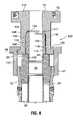
- FIG. 6is a schematic cross-sectional view of a second embodiment of a multi-lock adapter using a third embodiment of the lock down flange for secure connection to the prior art wellhead apparatus shown in FIG. 1 ;
- FIG. 7is a schematic cross-sectional view of the second embodiment of a multi-lock adapter using the third embodiment of the lock down flange for secure connection to the prior art wellhead apparatus shown in FIG. 2 ;
- FIG. 9is a schematic cross-sectional view of a second three-piece multi-lock adapter using the first embodiment of the lock down flange for secure connection to the prior art wellhead apparatus shown in FIG. 2 ;
- FIG. 10is a schematic cross-sectional view of a four-piece multi-lock adapter using the first embodiment of the lock down flange for secure connection to the prior art wellhead apparatus shown in FIG. 2 ;
- FIG. 11is a schematic cross-sectional view of a fifth lock down flange for secure connection to the prior art wellhead apparatus shown in FIG. 2 .
- the inventionprovides a lock down flange for providing a flanged connection to a casing mandrel of an independently screwed wellhead.
- the lock down flangemay be a multi-lock adapter for connecting a well stimulation tool, a blowout preventer, or a high pressure valve to a standard casing mandrel of a prior art independent screwed wellhead that only provides box threads for coupling the stimulation tool to the casing mandrel.
- the multi-lock adapterensures improved efficiency and safety while completing and/or re-completing wells. Efficiency is improved by enabling full-bore access to a casing of the well, and eliminating reliance on casing savers. Safety is improved by ensuring that stress on connection points to the wellhead during well stimulation procedures does not exceed engineered stress tolerances.
- FIG. 4is a schematic cross-sectional view of a multi-lock adapter 60 in accordance with the invention, secured to an independent screwed wellhead equipped with the prior art casing mandrel 20 ′.
- the multi-lock adapter 60includes a flanged adapter pin 62 having a pin-threaded nipple on a bottom end 64 for connection to the top box threads 38 of the casing mandrel 20 ′, an elongated hollow mandrel 66 that provides a coaxial extension of the axial passage 36 ′, and a top flanged end 68 .
- the top flanged end 68is adapted to support a high pressure valve, a blowout preventer or a well fracturing assembly, commonly referred to as a “fracstack”, in a manner well known in the art.
- the top flanged end 68provides an annular groove 70 for receiving a flange gasket, and a plurality of box threaded bores 72 for receiving and retaining respective flange bolts.
- the flanged adapter pin 62also includes an annular shoulder 74 for supporting a top lock-down nut 76 .
- the elongated hollow mandrel 66has a cylindrical outer wall that cooperates with an inner wall of a lockdown flange 80 to permit sliding and rotational movement of the lower part of the flanged adapter pin 62 within the lockdown flange 80 .
- the lockdown flange 80 , the lockdown nut 76 , and the flanged adapter pin 62together form the multi-lock adapter 60 of the present embodiment.
- the lockdown flange 80has a central passage with an interior wall 82 , a bottom end 84 for connection to the independent screwed wellhead 24 , and a top connector end 86 with connector pin threads 88 engaged by the top lockdown nut 76 .
- the interior wall 82includes a plurality of grooves 90 ( 3 shown) for retaining elastomeric seals, such as O-ring seals, in order to prevent fluid that may leak across an interface between the casing mandrel 20 ′ and the flanged adapter pin 62 , from escaping between the outer wall of the elongated hollow mandrel 66 and the interior wall 82 of the of the lockdown flange 80 .
- elastomeric sealssuch as O-ring seals
- the bottom end 84includes a radially extending flange with a bearing shoulder 92 that cooperates with a bottom lockdown nut 94 to permit the lockdown flange 80 to be secured to the independently screwed wellhead 24 . More specifically, the pin threads on the exterior periphery 37 of the wellhead 24 used to retain the casing mandrel 20 ′, are used to secure the bottom lockdown nut 94 .
- An annular groove 98 in a bottom surface 96 of the lockdown flange 80retains a fluid seal that prevents leakage of fluid between the lockdown flange 80 and the casing mandrel 20 ′.
- the multi-lock adapter 60is installed on the casing mandrel 20 ′ by inserting a seal in the annular groove 98 , and placing the lockdown flange 80 on the independent screwed wellhead 24 .
- the bottom lockdown nut 94is rotated to engage the pin threads 37 on the independent screwed wellhead 24 to provide a first lock to the wellhead.
- the flanged adapter pin 62is inserted into the lockdown flange 80 , and rotated so that the pin threads on the bottom end 64 threadedly engage the top box threads 38 of the casing mandrel 20 ′ until the flanged adapter pin 62 is securely connected to the casing mandrel 20 ′, providing the second lock between the multi-lock adapter 60 and the independent screwed wellhead 24 .
- the top lockdown nut 76is then placed over the flanged adapter pin 62 , and rotated into threaded engagement with the connector pin threads 88 to assemble the two parts of the multi-lock adapter 60 .
- the lockdown flange 80secures the flanged adapter pin 62 to the independent screwed wellhead 24 to reinforce the threaded coupling between the casing mandrel 20 ′ and the flanged adapter pin 62 .
- top lockdown nut 76with respect to the flanged adapter pin 62 is a matter of design choice. An embodiment showing an alternate placement of the top lockdown nut 76 is illustrated in FIG. 5 .
- FIG. 5is a schematic cross-sectional view of a multi-lock adapter 60 ′ in accordance with the invention that is the same as the embodiment illustrated in FIG. 4 except that a location of the top lockdown nut 74 ′ that secures the flanged adapter pin 62 to the lockdown flange 80 is changed.
- the outer wall of the elongated hollow mandrel 66 ′includes a section 65 of reduced diameter forming a supporting annular shoulder 74 ′ for rotatably retaining the top lockdown nut 76 ′.
- another example of a gasket for providing the fluid seal between the lockdown flange 80 and the top of the casing mandrel 20 ′is also shown.
- a pancake gasket 97is captively held in annular grooves in the bottom surface 96 ′ and a bottom of the elongated hollow mandrel 66 ′. A description of the remainder of the multi-lock adapter 60 ′ will not be repeated here, since the other components are the same as described above with reference to FIG. 4 .
- FIG. 6is a schematic cross-sectional view of another embodiment of multi-lock adapter 100 , which includes a threaded adapter pin 102 and a lockdown flange 104 .
- the threaded adapter pin 102is configured for threaded connection to the casing mandrel 20 of a Larkin-style independent screwed wellhead, and to the lockdown flange 104 .
- the threaded adapter pin 102is a cylindrical piece having a bottom end with a pin threaded nipple 106 for engaging the top box threads 38 of the casing mandrel 20 , and, at a top end of an exterior wall 108 , pin threads 110 for engaging complementary box threads of the lockdown flange 104 .
- An interior wall 112 of the threaded adapter pin 102provides an extension of the axial passage 36 , which is further extended by the lockdown flange 104 .
- the lockdown flange 104has a top flange 114 for securing a high pressure valve, blowout preventer, fracstack, or the like (none of which are shown) in fluid communication with the production casing 30 .
- An adapter pin chamber 116receives the threaded adapter pin 102 .
- the adapter pin chamber 116has a chamber wall 118 .
- the chamber wall 118includes box threads 120 complementary with the pin threads 110 on the exterior wall 108 of the threaded adapter pin 102 , and annular grooves 122 for receiving O-ring seals.
- the threaded adapter pin 102accommodates such variations by 1) providing a long nipple; and 2) accommodating a pancake gasket of a thickness selected to compensate for variations by providing a fluid seal in an annular gap 124 between a top end 117 of the adapter pin chamber 116 and the annular grooves 122 for retaining the O-ring seals. Any variation in insertion depth is therefore compensated for by a variable thickness of the pancake gasket inserted in the annular gap 124 . In this way the same multi-lock adapter 100 can be used on different casing mandrels 20 .
- the top flanged surface 114has the same features as the top flanged end 66 of the flanged adapter pin 62 of FIGS. 4 and 5 , and the bottom surface is substantially the same as the bottom connection surface 96 of the lockdown flange 80 shown in FIG. 4 , so those descriptions are not repeated.
- the outer periphery 128 of the lockdown flange 104includes an annular shoulder 130 for supporting a an elongated lockdown nut 132 that permits connection to the independent screwed wellhead 24 .
- the raised profile of the casing mandrel 20 to which the lockdown flange 104 is mountedvertically separates the bottom surface of the lockdown flange 104 from the independent screwed wellhead 24 . This vertical separation is compensated for by the extended length of the lockdown nut 132 .
- the threaded adapter pin 102is first screwed into the casing mandrel 20 .
- a distance the nipple extends above the top surface of the casing mandrel 20is measured to determine a height of the annular gap 124 , and therefore a thickness of the pancake gasket required.
- a suitable pancake gasketis selected and placed on a top end of the threaded adapter pin 102 .
- the lockdown flange 104is then lowered over the threaded adapter pin 102 , until the complementary box threads 120 of the lockdown flange 104 contact the pin threads 110 on the exterior wall 108 of the threaded adapter pin 102 .
- the lockdown flange 104is then rotated to engage the threads until the bottom connection surface 96 of the flanged adapter pin 104 rests against a top of the casing mandrel 20 , at which point the pancake gasket is compressed in a sealing operative condition between the top end 117 of the adapter pin chamber 116 , and a top end of the threaded adapter pin 102 .
- the lockdown nut 132is then secured to the exterior periphery 37 of the independent screwed wellhead 24 .
- FIG. 7is a schematic cross-sectional view of a multi-lock adapter 100 ′ similar to that shown in FIG. 6 , except that it is designed for coupling to the casing mandrel 20 ′ of the independently screwed wellhead assembly shown in FIG. 2 . Accordingly the extended length of the lockdown nut 132 is not required. Furthermore a flange gasket 98 ′ of the current embodiment is spaced nearer a periphery of the bottom surface 96 . It will be recognized that in this manner any of the lockdown flanges of the present invention can be adapted for use with either Larkin-style, or Wellhead Inc. independent screwed wellheads.
- FIG. 8schematically illustrates a cross-sectional view of a multi-lock adapter 150 having three parts: an adapter pin 152 , a pin sleeve 154 , and a lockdown flange 156 .
- the adapter pin 152resembles the adapter pin 102 of FIGS. 6 and 7 , except for the exterior wall 108 ′, which, is adapted to couple to the pin sleeve 154 , so that the coupled adapter pin 152 and pin sleeve 154 is inserted into an adapter pin chamber 116 ′ of the lockdown flange 156 .
- the exterior wall 108 ′ of the adapter pin 152is substantially cylindrical, having at a bottom edge, a neck region 158 that forms an annular step at a base of the nipple 106 .
- neck region 158Above the neck region 158 are adapter pin threads 160 for engaging complementary pin threads of the pin sleeve 154 .
- An upper region of the exterior wall 108 ′is a smooth cylinder and mates with a top part of the adapter pin chamber 116 ′.
- the lockdown flange 152resembles the lockdown flange 104 shown in FIG. 6 , except that the adapter pin chamber 116 ′ does not include any threads for engaging either the adapter pin 152 , or the pin sleeve 154 .
- the adapter pin chamber 116 ′includes a sealing section 164 above a sleeve chamber 166 .
- the sealing section 164includes the annular grooves 122 for receiving O-ring seals, or the like, to provide a fluid seal between the adapter pin 152 and the lockdown flange 156 .
- the sleeve chamber 166has an enlarged radius, and a smooth cylindrical inner wall.
- the pin sleeve 154has an inner surface that cooperates with the lower part of the exterior wall 108 ′ of the adapter pin 152 ; an outer surface that mates with the smooth cylindrical inner wall of the sealing section 166 of the lockdown flange 156 ; and a bottom surface for securely meeting a top of the casing mandrel 20 ′.
- the inner surfaceincludes an annular step 168 at the bottom that provides an enlarged base for bearing against the top of the casing mandrel 20 ′.
- the enlarged baseincludes an annular groove 170 for receiving a gasket, or the like.
- the neck region 158permits the pin sleeve 154 to be coaxially reciprocated with respect to the adapter pin 152 .
- the advantage of the current embodimentis that if the top box threads 38 of the casing mandrel 20 ′ are of a length that does not permit complete insertion of the adapter pin 152 , a position of the pin sleeve 154 is adjusted to provide a secure seating for the adapter pin 152 against the top surface of the casing mandrel. Adjusting of the pin sleeve 154 therefore provides readily apparent benefits for stabilizing the adapter pin 152 .
- the multi-lock adapter 150may be mounted to the wellhead 24 by inserting the adapter pin 152 into the pin sleeve 154 , and rotating the pin sleeve 154 to move it up above a bottom of the adapter pin 152 ′.
- the nipple 106 of the adapter pin 152is inserted into the top box threads 38 of the casing mandrel 20 ′, and screwed down.
- the pin sleeve 154is then lowered and tightened to make secure contact with the top of the casing mandrel 20 ′.
- the lockdown flange 156is then lowered over the adapter pin 152 and pin sleeve 154 , and locked into place using the lockdown nut 132 ′.
- Adapter pin threads 186are located above a neck region 188 of like form, arrangement and function as those ( 160 , 158 , respectively described above) shown in FIG. 8 .
- the lockdown flange 80is mounted to the independent screwed wellhead 24 using the bottom lockdown nut 94 , and then the flanged adapter pin 182 is inserted into the lockdown flange 80 , and when the pin threads of the nipple engage the top box threads 38 of the casing mandrel 20 ′, the top end of the flanged adapter pin 182 is rotated to threadably connect the flanged adapter pin 182 to the casing mandrel 20 ′.
- the bottom end of the adapter sleeve 154is securely seated against the top surface of the casing mandrel 20 ′.
- the flanged adapter pin 182is then secured to the lockdown flange 80 using the top lockdown nut 76 .
- FIG. 10schematically illustrates a 4-piece multi-lock adapter 200 in accordance with the invention.
- the multi-lock adapterincludes a flange connector 202 , an adapter pin 204 , the pin sleeve 154 , and the lockdown flange 80 .
- the flange connector 202provides the top flanged end 68 shown in FIG. 4 , including the annular shoulder 74 for supporting top lockdown nut 76 , and a mandrel with a pin-threaded nipple 206 .
- An outer wall of the mandrelseals against a top of the interior wall 82 of the lockdown flange 80 , which has the annular grooves 90 for receiving O-ring seals.
- a lower section of the adapter pin 204is the same as the adapter pin 152 shown in FIG. 8 .
- the nipple 106 for insertion into the casing mandrel 20 ′, the neck region 158 and the adapter pin threads 160 for engaging the pin sleeve 154have the same form and function as the corresponding features identified by like reference numerals in FIG. 8 .
- a top end of the adapter pin 204includes a box thread 208 , and annular O-ring grooves 210 , for permitting fluid-tight connection with the nipple 206 of the flange connector 202 .
- the advantage of this embodimentis that the adapter pin 204 can be inserted into the casing mandrel 20 ′ and the pin sleeve 154 can be lowered into secure position before the lockdown flange 80 is mounted to the independent screwed wellhead 24 .
- the flange connector 202is then screwed to the adapter pin 204 , and then fastened to the lockdown flange 80 using top lockdown nut 76 to complete the installation.
- the multi-lock adapters of the embodiments described aboveprovide full-bore access to the production casing 30 . Consequently, plugs, packers, perforating guns, fishing tools, and any other downhole tool or appliance can be run through these multi-lock adapters.
- the multi-lock adapters shown in the previous embodimentscan also be used in conjunction with a blowout preventer protector described in co-applicant's U.S. patent application Ser. No. 09/537,629 filed on Mar. 19, 2000, the specification of which is incorporated herein by reference, to permit a tubing string to be suspended in the well during well stimulation procedures.
- the tubing stringmay be used as a dead string to measure downhole pressures during well stimulation, or may be used as a fracturing string to permit well stimulation fluids to be pumped down the tubing string, and optionally down the annulus between the casing and the tubing string simultaneously.
- FIG. 11schematically illustrates an embodiment of a lockdown flange 220 in accordance with the invention connected to the casing mandrel 20 ′.
- the lockdown flange 220is mounted to a top of the casing mandrel 20 ′
- the lockdown flange 220includes top flanged end 68 a cylindrical mandrel 222 , and a bottom end 224 that includes an annular groove 226 for accommodating a high-pressure fluid seal, such as a flange gasket, well known in the art.
- the lockdown flange 220has an internal diameter that is greater than that of the axial passage through the casing mandrel 20 ′ to accommodate a blowout preventer protector described in co-applicant's U.S. Pat. No.
- the top flanged end 68provides a stud pad to which a blowout preventer (not shown) can be mounted.
- the blowout preventer protector (not shown)may then be mounted to a top of the blowout preventer.
- a mandrel of the blowout preventer protectoris stroked down through the blowout preventer and an annular sealing body on the bottom end of the blowout preventer protector mandrel seals off against an exposed annular portion 228 of a top of the casing mandrel 20 ′, or an inner surface of the mandrel 222 .
- the annular sealing bodyprovides a high pressure seal to ensure that high pressure well stimulation fluids cannot escape through the connection between the lockdown flange 220 and the casing mandrel 20 ′.
- the blowout preventer protectorprovides full-bore access to the well, and permits a tubing string to be suspended in the well during a well stimulation procedure.
- the lockdown flange 220further includes an annular shoulder 230 that supports a lockdown nut 232 .
- the lockdown nut 232has a box thread that engages the pin thread on the exterior periphery 37 of the casing mandrel 20 ′, to secure the lockdown flange 220 to the casing mandrel 20 ′.
- the tubing stringcan be run through the blowout preventer protector into or out of a live well at any time, and if a tubing string is not in the well, any downhole tool can be run into or out of the wellbore.
- the top box thread 38 of the casing mandrel 20 ′can be protected from erosion using a high pressure fluid seal for sealing against the exposed annular portion 228 as described in co-applicant's U.S. Pat. No. 6,247,537, which issued on Jun. 19, 2001.
- One embodiment of the high pressure fluid sealprovides an inner wall that extends downwardly past the pin thread 38 of the casing mandrel 20 ′ to prevent the pin thread 38 from being “washed out” by the abrasive proppants.
Landscapes
- Life Sciences & Earth Sciences (AREA)
- Engineering & Computer Science (AREA)
- Geology (AREA)
- Mining & Mineral Resources (AREA)
- Physics & Mathematics (AREA)
- Environmental & Geological Engineering (AREA)
- Fluid Mechanics (AREA)
- General Life Sciences & Earth Sciences (AREA)
- Geochemistry & Mineralogy (AREA)
- Earth Drilling (AREA)
- Pipe Accessories (AREA)
Abstract
Description
Claims (12)
Priority Applications (7)
| Application Number | Priority Date | Filing Date | Title |
|---|---|---|---|
| US10/607,921US7032677B2 (en) | 2003-06-27 | 2003-06-27 | Multi-lock adapters for independent screwed wellheads and methods of using same |
| CA002434804ACA2434804C (en) | 2003-06-27 | 2003-07-09 | Multi-lock adapters for independent screwed wellheads and methods of using same |
| US11/411,384US7267180B2 (en) | 2003-06-27 | 2006-04-25 | Multi-lock adapters for independent screwed wellheads and methods of using same |
| US11/890,906US7428931B2 (en) | 2003-06-27 | 2007-08-08 | Multi-lock adapters for independent screwed wellheads and methods of using same |
| US12/212,833US7708079B2 (en) | 2003-06-27 | 2008-09-18 | Multi-lock adapters for independent screwed wellheads and methods of using same |
| US12/751,589US7984758B2 (en) | 2003-06-27 | 2010-03-31 | Multi-lock adapters for independent screwed wellheads and methods of using same |
| US13/171,169US8100185B2 (en) | 2003-06-27 | 2011-06-28 | Multi-lock adapters for independent screwed wellheads and methods of using same |
Applications Claiming Priority (1)
| Application Number | Priority Date | Filing Date | Title |
|---|---|---|---|
| US10/607,921US7032677B2 (en) | 2003-06-27 | 2003-06-27 | Multi-lock adapters for independent screwed wellheads and methods of using same |
Related Child Applications (1)
| Application Number | Title | Priority Date | Filing Date |
|---|---|---|---|
| US11/411,384DivisionUS7267180B2 (en) | 2003-06-27 | 2006-04-25 | Multi-lock adapters for independent screwed wellheads and methods of using same |
Publications (2)
| Publication Number | Publication Date |
|---|---|
| US20040262012A1 US20040262012A1 (en) | 2004-12-30 |
| US7032677B2true US7032677B2 (en) | 2006-04-25 |
Family
ID=33540423
Family Applications (6)
| Application Number | Title | Priority Date | Filing Date |
|---|---|---|---|
| US10/607,921Expired - LifetimeUS7032677B2 (en) | 2003-06-27 | 2003-06-27 | Multi-lock adapters for independent screwed wellheads and methods of using same |
| US11/411,384Expired - LifetimeUS7267180B2 (en) | 2003-06-27 | 2006-04-25 | Multi-lock adapters for independent screwed wellheads and methods of using same |
| US11/890,906Expired - LifetimeUS7428931B2 (en) | 2003-06-27 | 2007-08-08 | Multi-lock adapters for independent screwed wellheads and methods of using same |
| US12/212,833Expired - Fee RelatedUS7708079B2 (en) | 2003-06-27 | 2008-09-18 | Multi-lock adapters for independent screwed wellheads and methods of using same |
| US12/751,589Expired - LifetimeUS7984758B2 (en) | 2003-06-27 | 2010-03-31 | Multi-lock adapters for independent screwed wellheads and methods of using same |
| US13/171,169Expired - Fee RelatedUS8100185B2 (en) | 2003-06-27 | 2011-06-28 | Multi-lock adapters for independent screwed wellheads and methods of using same |
Family Applications After (5)
| Application Number | Title | Priority Date | Filing Date |
|---|---|---|---|
| US11/411,384Expired - LifetimeUS7267180B2 (en) | 2003-06-27 | 2006-04-25 | Multi-lock adapters for independent screwed wellheads and methods of using same |
| US11/890,906Expired - LifetimeUS7428931B2 (en) | 2003-06-27 | 2007-08-08 | Multi-lock adapters for independent screwed wellheads and methods of using same |
| US12/212,833Expired - Fee RelatedUS7708079B2 (en) | 2003-06-27 | 2008-09-18 | Multi-lock adapters for independent screwed wellheads and methods of using same |
| US12/751,589Expired - LifetimeUS7984758B2 (en) | 2003-06-27 | 2010-03-31 | Multi-lock adapters for independent screwed wellheads and methods of using same |
| US13/171,169Expired - Fee RelatedUS8100185B2 (en) | 2003-06-27 | 2011-06-28 | Multi-lock adapters for independent screwed wellheads and methods of using same |
Country Status (2)
| Country | Link |
|---|---|
| US (6) | US7032677B2 (en) |
| CA (1) | CA2434804C (en) |
Cited By (21)
| Publication number | Priority date | Publication date | Assignee | Title |
|---|---|---|---|---|
| US20050092496A1 (en)* | 2002-02-19 | 2005-05-05 | Duhn Rex E. | Wellhead isolation tool and method of fracturing a well |
| US20070013188A1 (en)* | 2005-07-14 | 2007-01-18 | Hwces International | High-pressure threaded union with metal-to-metal seal, and metal ring gasket for same |
| US20070102150A1 (en)* | 2003-09-04 | 2007-05-10 | Oil States Energy Services, Inc. | Drilling flange and independent screwed wellhead with metal-to-metal seal and method of use |
| US20070107910A1 (en)* | 2004-03-17 | 2007-05-17 | Mcguire Bob | Hybrid wellhead system and method of use |
| US20070267198A1 (en)* | 2003-05-19 | 2007-11-22 | Stinger Wellhead Protection, Inc. | Casing mandrel for facilitating well completion, re-completion or workover |
| US20070272402A1 (en)* | 2002-02-19 | 2007-11-29 | Duhn Rex E | Wellhead isolation tool, wellhead assembly incorporating the same, and method of fracturing a well |
| US20070289748A1 (en)* | 2004-03-29 | 2007-12-20 | Hwces International | System and method for low-pressure well completion |
| US20080087439A1 (en)* | 2006-10-12 | 2008-04-17 | Stinger Wellhead Protection, Inc. | Configurable wellhead system with permanent fracturing spool and method of use |
| US20090025925A1 (en)* | 2003-06-27 | 2009-01-29 | Stinger Wellhead Protection, Inc. | Multi-lock adapters for independent screwed wellheads and methods of using same |
| US20090107685A1 (en)* | 2007-10-26 | 2009-04-30 | Weatherford/Lamb, Inc. | Wellhead Completion Assembly Capable of Versatile Arrangements |
| US20090160186A1 (en)* | 2007-12-19 | 2009-06-25 | Stinger Wellhead Protection, Inc. | Threaded union for tubulars used in high-pressure fluid applications |
| US20090236090A1 (en)* | 2008-03-20 | 2009-09-24 | Stinger Wellhead Protection, Inc. | Erosion Resistant Frac Head |
| US20120056413A1 (en)* | 2009-03-31 | 2012-03-08 | Cameron International Corporation | Multi-component tubular coupling for wellhead systems |
| US8256505B1 (en)* | 2006-01-23 | 2012-09-04 | James A Rose | Sealed well cellar |
| US8820400B2 (en) | 2008-03-20 | 2014-09-02 | Oil States Energy Services, L.L.C. | Erosion resistant frac head |
| US9366103B1 (en)* | 2015-09-21 | 2016-06-14 | Tech Energy Products, L.L.C. | Wellhead isolation tool and methods |
| US9441441B1 (en) | 2015-09-21 | 2016-09-13 | Tech Energy Products, L.L.C. | Wellsite connector apparatus and method |
| US9500306B2 (en)* | 2010-12-28 | 2016-11-22 | Beda Oxygentechnik Armaturen Gmbh | Multiple secured coupling device for oxygen lances |
| US11168532B2 (en) | 2020-03-06 | 2021-11-09 | Saudi Arabian Oil Company | Method and apparatus for sacrificial wellhead protector and testing adapter |
| US11208856B2 (en)* | 2018-11-02 | 2021-12-28 | Downing Wellhead Equipment, Llc | Subterranean formation fracking and well stack connector |
| US12252948B2 (en) | 2022-08-02 | 2025-03-18 | Klx Energy Services Llc | External wellhead sealing and clamping system |
Families Citing this family (17)
| Publication number | Priority date | Publication date | Assignee | Title |
|---|---|---|---|---|
| CA2444043C (en)* | 2003-10-08 | 2007-04-24 | L. Murray Dallas | Well stimulation tool and method for inserting a backpressure plug through a mandrel of the tool |
| CA2461233C (en)* | 2003-10-21 | 2007-11-13 | Bob Mcguire | Hybrid wellhead system and method of use |
| US7240735B2 (en)* | 2003-12-10 | 2007-07-10 | Vetco Gray Inc. | Subsea wellhead assembly |
| US7775288B2 (en)* | 2006-10-06 | 2010-08-17 | Stinger Wellhead Protection, Inc. | Retrievable frac mandrel and well control stack to facilitate well completion, re-completion or workover and method of use |
| WO2009154881A1 (en)* | 2008-06-19 | 2009-12-23 | Cameron International Corporation | Frac adapter for wellhead |
| NO333681B1 (en)* | 2009-01-08 | 2013-08-12 | Aker Subsea As | Underwater auxiliary compensator |
| US8327943B2 (en)* | 2009-11-12 | 2012-12-11 | Vetco Gray Inc. | Wellhead isolation protection sleeve |
| US20110280668A1 (en)* | 2009-11-16 | 2011-11-17 | Rn Motion Technologies | Hang-Off Adapter for Offshore Riser Systems and Associated Methods |
| US8573328B1 (en) | 2010-05-04 | 2013-11-05 | Cameron West Coast Inc. | Hydrocarbon well completion system and method of completing a hydrocarbon well |
| EP2593638B1 (en) | 2010-07-15 | 2019-01-09 | Deep Sea Innovations, LLC | Apparatuses and methods for closing and reopening a pipe |
| US8826990B2 (en) | 2010-07-15 | 2014-09-09 | Deep Sea Innovations, Llc | Apparatuses and methods for closing and reopening a pipe |
| US8746351B2 (en)* | 2011-06-23 | 2014-06-10 | Wright's Well Control Services, Llc | Method for stabilizing oilfield equipment |
| CN107288581B (en)* | 2017-07-28 | 2019-04-23 | 中国海洋石油集团有限公司 | Marine self-propelled installing wellhead work implement |
| US11280147B2 (en)* | 2018-02-28 | 2022-03-22 | Oil States Energy Services, L.L.C. | Mandrel head for wellhead isolation tool and method of use |
| CN111121211B (en)* | 2020-01-15 | 2025-08-08 | 广州市亿加环境科技有限公司 | A single-hole heat exchanger |
| CN112502657B (en)* | 2020-11-16 | 2022-07-05 | 中国石油天然气股份有限公司 | Packing box, production tree equipment and oil production system |
| CN115898314B (en)* | 2023-01-06 | 2023-05-05 | 通化易达石油化工设备制造有限公司 | Pressure-releasing-controllable anti-theft blowout preventer for oil gas wellhead |
Citations (21)
| Publication number | Priority date | Publication date | Assignee | Title |
|---|---|---|---|---|
| US2109031A (en)* | 1936-07-16 | 1938-02-22 | Gulf Coast Machine & Supply Co | Full hole casing or tubing head |
| US3158389A (en)* | 1960-08-10 | 1964-11-24 | Clyde T Turner | Gas and oil well casing head assembly |
| US3343603A (en) | 1965-08-02 | 1967-09-26 | Exxon Production Research Co | Wellhead for multiple low-pressure wells |
| US3675719A (en) | 1970-10-16 | 1972-07-11 | Damon T Slator | Tubing hanger assembly and method of using same |
| US4353420A (en) | 1980-10-31 | 1982-10-12 | Cameron Iron Works, Inc. | Wellhead apparatus and method of running same |
| US4993488A (en) | 1988-11-02 | 1991-02-19 | Mcleod Roderick D | Well casing packers |
| US5092401A (en) | 1989-08-17 | 1992-03-03 | Shell Oil Company | Wellhead assembly |
| US5103900A (en)* | 1989-09-28 | 1992-04-14 | Mcleod Roderick D | High pressure adapter for well-heads |
| US5605194A (en) | 1995-06-19 | 1997-02-25 | J. M. Huber Corporation | Independent screwed wellhead with high pressure capability and method |
| US5660234A (en) | 1996-02-01 | 1997-08-26 | Abb Vetco Gray Inc. | Shallow flow wellhead system |
| US6179053B1 (en) | 1999-08-12 | 2001-01-30 | L. Murray Dallas | Lockdown mechanism for well tools requiring fixed-point packoff |
| US6196323B1 (en) | 1996-05-24 | 2001-03-06 | Mercur Slimhole Drilling And Intervention As | Well head system |
| US6220363B1 (en) | 1999-07-16 | 2001-04-24 | L. Murray Dallas | Wellhead isolation tool and method of using same |
| US6247537B1 (en) | 1999-04-23 | 2001-06-19 | L. Murray Dallas | High pressure fluid seal for sealing against a bit guide in a wellhead and method of using |
| US6289993B1 (en) | 1999-06-21 | 2001-09-18 | L. Murray Dallas | Blowout preventer protector and setting tool |
| US6364024B1 (en) | 2000-01-28 | 2002-04-02 | L. Murray Dallas | Blowout preventer protector and method of using same |
| US20020117298A1 (en) | 2000-09-29 | 2002-08-29 | Henry Wong | Wellhead lsolation tool |
| US6491098B1 (en) | 2000-11-07 | 2002-12-10 | L. Murray Dallas | Method and apparatus for perforating and stimulating oil wells |
| US6626245B1 (en) | 2000-03-29 | 2003-09-30 | L Murray Dallas | Blowout preventer protector and method of using same |
| US6769489B2 (en) | 2001-11-28 | 2004-08-03 | L. Murray Dallas | Well stimulation tool and method of using same |
| US6817423B2 (en) | 2002-06-03 | 2004-11-16 | L. Murray Dallas | Wall stimulation tool and method of using same |
Family Cites Families (5)
| Publication number | Priority date | Publication date | Assignee | Title |
|---|---|---|---|---|
| CA2366404A1 (en)* | 2001-12-21 | 2003-06-21 | Murray L. Dallas | Slip spool and method of using same |
| CA2415631A1 (en)* | 2003-01-03 | 2004-07-03 | L. Murray Dallas | Backpressure adapter pin and method of use |
| US6938696B2 (en)* | 2003-01-06 | 2005-09-06 | H W Ces International | Backpressure adapter pin and methods of use |
| CA2428613C (en)* | 2003-05-13 | 2005-10-25 | Bob Mcguire | Casing mandrel with well stimulation tool and tubing head spool for use with the casing mandrel |
| US7032677B2 (en)* | 2003-06-27 | 2006-04-25 | H W Ces International | Multi-lock adapters for independent screwed wellheads and methods of using same |
- 2003
- 2003-06-27USUS10/607,921patent/US7032677B2/ennot_activeExpired - Lifetime
- 2003-07-09CACA002434804Apatent/CA2434804C/ennot_activeExpired - Fee Related
- 2006
- 2006-04-25USUS11/411,384patent/US7267180B2/ennot_activeExpired - Lifetime
- 2007
- 2007-08-08USUS11/890,906patent/US7428931B2/ennot_activeExpired - Lifetime
- 2008
- 2008-09-18USUS12/212,833patent/US7708079B2/ennot_activeExpired - Fee Related
- 2010
- 2010-03-31USUS12/751,589patent/US7984758B2/ennot_activeExpired - Lifetime
- 2011
- 2011-06-28USUS13/171,169patent/US8100185B2/ennot_activeExpired - Fee Related
Patent Citations (22)
| Publication number | Priority date | Publication date | Assignee | Title |
|---|---|---|---|---|
| US2109031A (en)* | 1936-07-16 | 1938-02-22 | Gulf Coast Machine & Supply Co | Full hole casing or tubing head |
| US3158389A (en)* | 1960-08-10 | 1964-11-24 | Clyde T Turner | Gas and oil well casing head assembly |
| US3343603A (en) | 1965-08-02 | 1967-09-26 | Exxon Production Research Co | Wellhead for multiple low-pressure wells |
| US3675719A (en) | 1970-10-16 | 1972-07-11 | Damon T Slator | Tubing hanger assembly and method of using same |
| US4353420A (en) | 1980-10-31 | 1982-10-12 | Cameron Iron Works, Inc. | Wellhead apparatus and method of running same |
| US4993488A (en) | 1988-11-02 | 1991-02-19 | Mcleod Roderick D | Well casing packers |
| US5092401A (en) | 1989-08-17 | 1992-03-03 | Shell Oil Company | Wellhead assembly |
| US5103900A (en)* | 1989-09-28 | 1992-04-14 | Mcleod Roderick D | High pressure adapter for well-heads |
| US5605194A (en) | 1995-06-19 | 1997-02-25 | J. M. Huber Corporation | Independent screwed wellhead with high pressure capability and method |
| US5660234A (en) | 1996-02-01 | 1997-08-26 | Abb Vetco Gray Inc. | Shallow flow wellhead system |
| US6196323B1 (en) | 1996-05-24 | 2001-03-06 | Mercur Slimhole Drilling And Intervention As | Well head system |
| US6247537B1 (en) | 1999-04-23 | 2001-06-19 | L. Murray Dallas | High pressure fluid seal for sealing against a bit guide in a wellhead and method of using |
| US6289993B1 (en) | 1999-06-21 | 2001-09-18 | L. Murray Dallas | Blowout preventer protector and setting tool |
| US6220363B1 (en) | 1999-07-16 | 2001-04-24 | L. Murray Dallas | Wellhead isolation tool and method of using same |
| US6179053B1 (en) | 1999-08-12 | 2001-01-30 | L. Murray Dallas | Lockdown mechanism for well tools requiring fixed-point packoff |
| US6364024B1 (en) | 2000-01-28 | 2002-04-02 | L. Murray Dallas | Blowout preventer protector and method of using same |
| US6626245B1 (en) | 2000-03-29 | 2003-09-30 | L Murray Dallas | Blowout preventer protector and method of using same |
| US6817421B2 (en) | 2000-03-29 | 2004-11-16 | L. Murray Dallas | Blowout preventer protector and method of using same |
| US20020117298A1 (en) | 2000-09-29 | 2002-08-29 | Henry Wong | Wellhead lsolation tool |
| US6491098B1 (en) | 2000-11-07 | 2002-12-10 | L. Murray Dallas | Method and apparatus for perforating and stimulating oil wells |
| US6769489B2 (en) | 2001-11-28 | 2004-08-03 | L. Murray Dallas | Well stimulation tool and method of using same |
| US6817423B2 (en) | 2002-06-03 | 2004-11-16 | L. Murray Dallas | Wall stimulation tool and method of using same |
Non-Patent Citations (4)
| Title |
|---|
| U.S. Appl. No. 10/327,268, entitled "Slip Spool and Method of Using Same," filed Dec. 20, 2002. |
| U.S. Appl. No. 10/336,911, entitled "Backpressure Adapter Pin and Methods of Use," filed Jan. 6, 2003. |
| U.S. Appl. No. 10/440,795 entitled "Casing Mandrel with Well Stimulation Tool and Tubing Head Spool for Use with the Casing Mandrel," filed May 19, 2003. |
| U.S. Appl. No. 10/912,894, entitled "Backpressure Adapter Pin and Methods of Use," filed Aug. 6, 2004. |
Cited By (73)
| Publication number | Priority date | Publication date | Assignee | Title |
|---|---|---|---|---|
| US8863829B2 (en) | 2002-02-19 | 2014-10-21 | Seaboard International Inc. | Wellhead isolation tool and wellhead assembly incorporating the same |
| US8272433B2 (en) | 2002-02-19 | 2012-09-25 | Seaboard International Inc. | Wellhead isolation tool and wellhead assembly incorporating the same |
| US7493944B2 (en) | 2002-02-19 | 2009-02-24 | Duhn Oil Tool, Inc. | Wellhead isolation tool and method of fracturing a well |
| US20100193178A1 (en)* | 2002-02-19 | 2010-08-05 | Duhn Rex E | Wellhead isolation tool and wellhead assembly incorporating the same |
| US8333237B2 (en) | 2002-02-19 | 2012-12-18 | Seaboard International Inc. | Wellhead isolation tool and wellhead assembly incorporating the same |
| US20070272402A1 (en)* | 2002-02-19 | 2007-11-29 | Duhn Rex E | Wellhead isolation tool, wellhead assembly incorporating the same, and method of fracturing a well |
| US7416020B2 (en) | 2002-02-19 | 2008-08-26 | Duhn Oil Tool, Inc. | Wellhead isolation tool, wellhead assembly incorporating the same, and method of fracturing a well |
| US7726393B2 (en) | 2002-02-19 | 2010-06-01 | Duhn Oil Tool, Inc. | Wellhead isolation tool and wellhead assembly incorporating the same |
| US20050092496A1 (en)* | 2002-02-19 | 2005-05-05 | Duhn Rex E. | Wellhead isolation tool and method of fracturing a well |
| US20110180252A1 (en)* | 2003-05-13 | 2011-07-28 | Stinger Wellhead Protection, Inc. | Casing mandrel for facilitating well completion, re-completion or workover |
| US20100012329A1 (en)* | 2003-05-13 | 2010-01-21 | Stinger Wellhead Protection, Inc. | Casing mandrel for facilitating well completion, re-completion or workover |
| US8157005B2 (en) | 2003-05-13 | 2012-04-17 | Stinger Wellhead Protection, Inc. | Casing mandrel for facilitating well completion, re-completion or workover |
| US7921923B2 (en) | 2003-05-13 | 2011-04-12 | Stinger Wellhead Protection, Inc. | Casing mandrel for facilitating well completion, re-completion or workover |
| US7604058B2 (en) | 2003-05-19 | 2009-10-20 | Stinger Wellhead Protection, Inc. | Casing mandrel for facilitating well completion, re-completion or workover |
| US20070267198A1 (en)* | 2003-05-19 | 2007-11-22 | Stinger Wellhead Protection, Inc. | Casing mandrel for facilitating well completion, re-completion or workover |
| US7708079B2 (en) | 2003-06-27 | 2010-05-04 | Stinger Wellhead Protection, Inc. | Multi-lock adapters for independent screwed wellheads and methods of using same |
| US20100181063A1 (en)* | 2003-06-27 | 2010-07-22 | Stinger Wellhead Protection, Inc. | Multi-lock adapters for independent screwed wellheads and methods of using same |
| US8100185B2 (en) | 2003-06-27 | 2012-01-24 | Stinger Wellhead Protection, Inc. | Multi-lock adapters for independent screwed wellheads and methods of using same |
| US20090025925A1 (en)* | 2003-06-27 | 2009-01-29 | Stinger Wellhead Protection, Inc. | Multi-lock adapters for independent screwed wellheads and methods of using same |
| US7984758B2 (en) | 2003-06-27 | 2011-07-26 | Stinger Wellhead Protection, Inc. | Multi-lock adapters for independent screwed wellheads and methods of using same |
| US20090084538A1 (en)* | 2003-09-04 | 2009-04-02 | Stinger Wellhead Protection, Inc. | Drilling flange and independent screwed wellhead with metal-to-metal seal and method of use |
| US7650936B2 (en) | 2003-09-04 | 2010-01-26 | Stinger Wellhead Protection, Inc. | Drilling flange and independent screwed wellhead with metal-to-metal seal and method of use |
| US20070102150A1 (en)* | 2003-09-04 | 2007-05-10 | Oil States Energy Services, Inc. | Drilling flange and independent screwed wellhead with metal-to-metal seal and method of use |
| US7350562B2 (en) | 2003-09-04 | 2008-04-01 | Stinger Wellhead Protection, Inc. | Drilling flange and independent screwed wellhead with metal-to-metal seal and method of use |
| US7475721B2 (en) | 2003-09-04 | 2009-01-13 | Stinger Wellhead Protection, Inc. | Drilling flange and independent screwed wellhead with metal-to-metal seal and method of use |
| US20080142210A1 (en)* | 2003-09-04 | 2008-06-19 | Stinger Wellhead Protection, Inc. | Drilling Flange and Independent Screwed Wellhead With Metal-to-Metal Seal and Method of Use |
| US20080087415A1 (en)* | 2004-03-17 | 2008-04-17 | Stinger Wellhead Protection, Inc. | Hybrid wellhead system and method of use |
| US7395867B2 (en) | 2004-03-17 | 2008-07-08 | Stinger Wellhead Protection, Inc. | Hybrid wellhead system and method of use |
| US20110198074A1 (en)* | 2004-03-17 | 2011-08-18 | Stinger Wellhead Protection, Inc. | Hybrid wellhead system and method of use |
| US7721808B2 (en) | 2004-03-17 | 2010-05-25 | Stinger Wellhead Protection, Inc. | Hybrid wellhead system and method of use |
| US7481269B2 (en) | 2004-03-17 | 2009-01-27 | Stinger Wellhead Protection, Inc. | Hybrid wellhead system and method of use |
| US20070107910A1 (en)* | 2004-03-17 | 2007-05-17 | Mcguire Bob | Hybrid wellhead system and method of use |
| US8118090B2 (en) | 2004-03-17 | 2012-02-21 | Stinger Wellhead Protection, Inc. | Hybrid wellhead system and method of use |
| US20100218939A1 (en)* | 2004-03-17 | 2010-09-02 | Stinger Wellhead Protection, Inc. | Hybrid wellhead system and method of use |
| US7905293B2 (en) | 2004-03-17 | 2011-03-15 | Stinger Wellhead Protection, Inc. | Hybrid wellhead system and method of use |
| US7886833B2 (en) | 2004-03-29 | 2011-02-15 | Stinger Wellhead Protection, Inc. | System and method for low-pressure well completion |
| US20070289748A1 (en)* | 2004-03-29 | 2007-12-20 | Hwces International | System and method for low-pressure well completion |
| US10267115B2 (en) | 2005-07-12 | 2019-04-23 | Oil States Energy Services, L.L.C. | Wellhead isolation tool and methods |
| US8205916B2 (en) | 2005-07-14 | 2012-06-26 | Stinger Wellhead Protection, Inc. | High-pressure threaded union with metal-to-metal seal, and metal ring gasket for same |
| US7654585B2 (en) | 2005-07-14 | 2010-02-02 | Stinger Wellhead Protection, Inc. | High-pressure threaded union with metal-to-metal seal, and metal ring gasket for same |
| US20070013188A1 (en)* | 2005-07-14 | 2007-01-18 | Hwces International | High-pressure threaded union with metal-to-metal seal, and metal ring gasket for same |
| US7484776B2 (en) | 2005-07-14 | 2009-02-03 | Stinger Wellhead Protection, Inc. | High-pressure threaded union with metal-to-metal seal, and metal ring gasket for same |
| US7922216B2 (en) | 2005-07-14 | 2011-04-12 | Stinger Wellhead Protection, Inc. | High-pressure threaded union with metal-to-metal seal, and metal ring gasket for same |
| US20090091131A1 (en)* | 2005-07-14 | 2009-04-09 | Stinger Wellhead Protection, Inc. | High-pressure threaded union with metal-to-metal seal, and metal ring gasket for same |
| US20110175349A1 (en)* | 2005-07-14 | 2011-07-21 | Stinger Wellhead Protection, Inc. | High-pressure threaded union with metal-to-metal seal, and metal ring gasket for same |
| US8256505B1 (en)* | 2006-01-23 | 2012-09-04 | James A Rose | Sealed well cellar |
| US20090283277A1 (en)* | 2006-10-12 | 2009-11-19 | Stinger Wellhead Protection, Inc. | Configurable wellhead system with permanent fracturing spool and method of use |
| US7857062B2 (en) | 2006-10-12 | 2010-12-28 | Stinger Wellhead Protection, Inc. | Configurable wellhead system with permanent fracturing spool and method of use |
| US20080087439A1 (en)* | 2006-10-12 | 2008-04-17 | Stinger Wellhead Protection, Inc. | Configurable wellhead system with permanent fracturing spool and method of use |
| US7578351B2 (en) | 2006-10-12 | 2009-08-25 | Stinger Wellhead Protection, Inc. | Configurable wellhead system with permanent fracturing spool and method of use |
| US20100288483A1 (en)* | 2007-10-26 | 2010-11-18 | Weatherford/Lamb, Inc. | Wellhead Completion Assembly Capable of Versatile Arrangements |
| US9140092B2 (en) | 2007-10-26 | 2015-09-22 | Weatherford Technology Holdings, Llc | Wellhead completion assembly capable of versatile arrangements |
| US7779921B2 (en) | 2007-10-26 | 2010-08-24 | Weatherford/Lamb, Inc. | Wellhead completion assembly capable of versatile arrangements |
| USRE46241E1 (en) | 2007-10-26 | 2016-12-20 | Weatherford Technology Holdings, Llc | Wellhead completion assembly capable of versatile arrangements |
| US20090107685A1 (en)* | 2007-10-26 | 2009-04-30 | Weatherford/Lamb, Inc. | Wellhead Completion Assembly Capable of Versatile Arrangements |
| US8567827B2 (en) | 2007-12-19 | 2013-10-29 | Oil States Energy Services, L.L.C. | Threaded union for tubulars used in high-pressure fluid applications |
| US20090160186A1 (en)* | 2007-12-19 | 2009-06-25 | Stinger Wellhead Protection, Inc. | Threaded union for tubulars used in high-pressure fluid applications |
| US9097369B2 (en) | 2007-12-19 | 2015-08-04 | Oil States Energy Services, L.L.C. | Threaded union for tubulars used in high-pressure fluid applications |
| US7984932B2 (en) | 2007-12-19 | 2011-07-26 | Stinger Wellhead Protection, Inc. | Threaded union for tubulars used in high-pressure fluid applications |
| US7789133B2 (en) | 2008-03-20 | 2010-09-07 | Stinger Wellhead Protection, Inc. | Erosion resistant frac head |
| US20100326648A1 (en)* | 2008-03-20 | 2010-12-30 | Stinger Wellhead Protection, Inc. | Erosion resistant frac head |
| US8820400B2 (en) | 2008-03-20 | 2014-09-02 | Oil States Energy Services, L.L.C. | Erosion resistant frac head |
| US20090236090A1 (en)* | 2008-03-20 | 2009-09-24 | Stinger Wellhead Protection, Inc. | Erosion Resistant Frac Head |
| US8016031B2 (en) | 2008-03-20 | 2011-09-13 | Stinger Wellhead Protection, Inc. | Erosion resistant frac head |
| US20120056413A1 (en)* | 2009-03-31 | 2012-03-08 | Cameron International Corporation | Multi-component tubular coupling for wellhead systems |
| US9790759B2 (en) | 2009-03-31 | 2017-10-17 | Cameron International Corporation | Multi-component tubular coupling for wellhead systems |
| US8893774B2 (en)* | 2009-03-31 | 2014-11-25 | Cameron International Corporation | Multi-component tubular coupling for wellhead systems |
| US9500306B2 (en)* | 2010-12-28 | 2016-11-22 | Beda Oxygentechnik Armaturen Gmbh | Multiple secured coupling device for oxygen lances |
| US9441441B1 (en) | 2015-09-21 | 2016-09-13 | Tech Energy Products, L.L.C. | Wellsite connector apparatus and method |
| US9366103B1 (en)* | 2015-09-21 | 2016-06-14 | Tech Energy Products, L.L.C. | Wellhead isolation tool and methods |
| US11208856B2 (en)* | 2018-11-02 | 2021-12-28 | Downing Wellhead Equipment, Llc | Subterranean formation fracking and well stack connector |
| US11168532B2 (en) | 2020-03-06 | 2021-11-09 | Saudi Arabian Oil Company | Method and apparatus for sacrificial wellhead protector and testing adapter |
| US12252948B2 (en) | 2022-08-02 | 2025-03-18 | Klx Energy Services Llc | External wellhead sealing and clamping system |
Also Published As
| Publication number | Publication date |
|---|---|
| US20060196677A1 (en) | 2006-09-07 |
| US7984758B2 (en) | 2011-07-26 |
| US20110253384A1 (en) | 2011-10-20 |
| US20070277968A1 (en) | 2007-12-06 |
| US7708079B2 (en) | 2010-05-04 |
| US20100181063A1 (en) | 2010-07-22 |
| US7267180B2 (en) | 2007-09-11 |
| US20090025925A1 (en) | 2009-01-29 |
| CA2434804A1 (en) | 2004-12-27 |
| CA2434804C (en) | 2005-11-15 |
| US7428931B2 (en) | 2008-09-30 |
| US8100185B2 (en) | 2012-01-24 |
| US20040262012A1 (en) | 2004-12-30 |
Similar Documents
| Publication | Publication Date | Title |
|---|---|---|
| US7267180B2 (en) | Multi-lock adapters for independent screwed wellheads and methods of using same | |
| US7040410B2 (en) | Adapters for double-locking casing mandrel and method of using same | |
| US7422070B2 (en) | Casing mandrel with well stimulation tool and tubing head spool for use with the casing mandrel | |
| US7604058B2 (en) | Casing mandrel for facilitating well completion, re-completion or workover | |
| US7886833B2 (en) | System and method for low-pressure well completion | |
| US7159663B2 (en) | Hybrid wellhead system and method of use | |
| US7481269B2 (en) | Hybrid wellhead system and method of use | |
| US6817423B2 (en) | Wall stimulation tool and method of using same | |
| US7243733B2 (en) | Cup tool for a high-pressure mandrel and method of using same | |
| CA2512263C (en) | Cup tool for a high-pressure mandrel and method of using same |
Legal Events
| Date | Code | Title | Description |
|---|---|---|---|
| AS | Assignment | Owner name:HWCES INTERNATIONAL, C/O OIL STATES INTERNATIONAL, Free format text:ASSIGNMENT OF ASSIGNORS INTEREST;ASSIGNORS:DALLAS, L MURRAY;MCGUIRE, BOB;REEL/FRAME:016713/0171 Effective date:20050501 | |
| AS | Assignment | Owner name:HWC ENERGY SERVICES, INC., TEXAS Free format text:ASSIGNMENT OF ASSIGNORS INTEREST;ASSIGNOR:HWCES INTERNATIONAL;REEL/FRAME:017636/0559 Effective date:20060228 | |
| STCF | Information on status: patent grant | Free format text:PATENTED CASE | |
| AS | Assignment | Owner name:OIL STATES ENERGY SERVICES, INC, TEXAS Free format text:CHANGE OF NAME;ASSIGNOR:HWC ENERGY SERVICE, INC.;REEL/FRAME:017957/0310 Effective date:20060309 | |
| AS | Assignment | Owner name:STINGER WELLHEAD PROTECTION, INC., TEXAS Free format text:ASSIGNMENT OF ASSIGNORS INTEREST;ASSIGNOR:OIL STATES ENERGY SERVICES, INC.;REEL/FRAME:018767/0230 Effective date:20061219 | |
| CC | Certificate of correction | ||
| AS | Assignment | Owner name:STINGER WELLHEAD PROTECTION, INC., OKLAHOMA Free format text:CHANGE OF ASSIGNEE ADDRESS;ASSIGNOR:STINGER WELLHEAD PROTECTION, INC.;REEL/FRAME:019588/0172 Effective date:20070716 Owner name:STINGER WELLHEAD PROTECTION, INC.,OKLAHOMA Free format text:CHANGE OF ASSIGNEE ADDRESS;ASSIGNOR:STINGER WELLHEAD PROTECTION, INC.;REEL/FRAME:019588/0172 Effective date:20070716 | |
| FPAY | Fee payment | Year of fee payment:4 | |
| AS | Assignment | Owner name:OIL STATES ENERGY SERVICES, L.L.C., TEXAS Free format text:MERGER;ASSIGNOR:STINGER WELLHEAD PROTECTION, INCORPORATED;REEL/FRAME:029130/0379 Effective date:20111231 | |
| FPAY | Fee payment | Year of fee payment:8 | |
| MAFP | Maintenance fee payment | Free format text:PAYMENT OF MAINTENANCE FEE, 12TH YEAR, LARGE ENTITY (ORIGINAL EVENT CODE: M1553) Year of fee payment:12 | |
| AS | Assignment | Owner name:WELLS FARGO BANK, NATIONAL ASSOCIATION, GEORGIA Free format text:ASSIGNMENT OF ASSIGNORS INTEREST;ASSIGNOR:OIL STATES INTERNATIONAL, INC.;REEL/FRAME:055314/0482 Effective date:20210210 |