US7031997B2 - Method and apparatus for connecting terminals in a remote consulting system - Google Patents
Method and apparatus for connecting terminals in a remote consulting systemDownload PDFInfo
- Publication number
- US7031997B2 US7031997B2US09/846,615US84661501AUS7031997B2US 7031997 B2US7031997 B2US 7031997B2US 84661501 AUS84661501 AUS 84661501AUS 7031997 B2US7031997 B2US 7031997B2
- Authority
- US
- United States
- Prior art keywords
- terminal
- clerk
- expert
- connectable
- customer
- Prior art date
- Legal status (The legal status is an assumption and is not a legal conclusion. Google has not performed a legal analysis and makes no representation as to the accuracy of the status listed.)
- Expired - Fee Related, expires
Links
Images


Classifications
- H—ELECTRICITY
- H04—ELECTRIC COMMUNICATION TECHNIQUE
- H04L—TRANSMISSION OF DIGITAL INFORMATION, e.g. TELEGRAPHIC COMMUNICATION
- H04L12/00—Data switching networks
- H04L12/02—Details
- H04L12/16—Arrangements for providing special services to substations
- H04L12/18—Arrangements for providing special services to substations for broadcast or conference, e.g. multicast
- H04L12/1813—Arrangements for providing special services to substations for broadcast or conference, e.g. multicast for computer conferences, e.g. chat rooms
- H04L12/1822—Conducting the conference, e.g. admission, detection, selection or grouping of participants, correlating users to one or more conference sessions, prioritising transmission
- H—ELECTRICITY
- H04—ELECTRIC COMMUNICATION TECHNIQUE
- H04L—TRANSMISSION OF DIGITAL INFORMATION, e.g. TELEGRAPHIC COMMUNICATION
- H04L12/00—Data switching networks
- H04L12/02—Details
- H04L12/16—Arrangements for providing special services to substations
- H04L12/18—Arrangements for providing special services to substations for broadcast or conference, e.g. multicast
- H04L12/1813—Arrangements for providing special services to substations for broadcast or conference, e.g. multicast for computer conferences, e.g. chat rooms
- H—ELECTRICITY
- H04—ELECTRIC COMMUNICATION TECHNIQUE
- H04M—TELEPHONIC COMMUNICATION
- H04M3/00—Automatic or semi-automatic exchanges
- H04M3/42—Systems providing special services or facilities to subscribers
- H04M3/50—Centralised arrangements for answering calls; Centralised arrangements for recording messages for absent or busy subscribers ; Centralised arrangements for recording messages
- H04M3/51—Centralised call answering arrangements requiring operator intervention, e.g. call or contact centers for telemarketing
- H—ELECTRICITY
- H04—ELECTRIC COMMUNICATION TECHNIQUE
- H04M—TELEPHONIC COMMUNICATION
- H04M3/00—Automatic or semi-automatic exchanges
- H04M3/42—Systems providing special services or facilities to subscribers
- H04M3/58—Arrangements for transferring received calls from one subscriber to another; Arrangements affording interim conversations between either the calling or the called party and a third party
- H—ELECTRICITY
- H04—ELECTRIC COMMUNICATION TECHNIQUE
- H04L—TRANSMISSION OF DIGITAL INFORMATION, e.g. TELEGRAPHIC COMMUNICATION
- H04L51/00—User-to-user messaging in packet-switching networks, transmitted according to store-and-forward or real-time protocols, e.g. e-mail
- H04L51/21—Monitoring or handling of messages
- H04L51/23—Reliability checks, e.g. acknowledgments or fault reporting
Definitions
- the present inventionrelates to a method and apparatus for connecting a lobby terminal to a special clerk terminal for corresponding to a consulting detail in a remote consulting support system using a network.
- connection methods between a lobby terminal and a remote service terminalthere is a method of realizing dispersion of processing load for avoiding concentrated connection to a specific terminal.
- a remote service manager controlling remote service terminals for supplying information in a uniform mannersounds out each remote service terminal as to whether information can be supplied.
- each terminalreturns the load value thereof to the remote service manager.
- the remote service managerselects the remote service terminal having the minimum among the load values returned from the remote service terminals, connects the terminal, and supplies information to it.
- a prior art for realizing such a functionis described in Japanese Patent Application Laid-Open 5-134959.
- a counselor in charge of consultationsends information that he leaves his seat to the communication control unit for batch controlling telephone connection when he leaves his seat.
- the communication control unitstores the inquiry information from the user in the communication control unit.
- the communication control unitsends the inquiry information sent to the counselor during leaving his seat to the counselor.
- the remote service managerfor batch controlling the remote service terminals, decides the remote service terminal to be connected, the remote service manager aeces ses each remote service terminal and reads and decides information (load value) about connectable or not.
- Each remote service terminalrequires a process of changing the load value of the own terminal whenever it is connected.
- the batch controlling remote service managerjudges the decision of the remote service terminal to be connected on the basis of only the load values of all the remote service terminals. Therefore, even if the consulting detail is the same, a specific remote service terminal cannot be always connected. Therefore, a terminal such that a special expert clerk corresponding to a specific consulting detail operates from a remote service terminal cannot be connected.
- the present inventionconnects a lobby terminal to a clerk terminal conforming to the consulting detail of the user according to the main procedure indicated below.
- the lobby terminalreceives the information from the server for making a connection with clerk terminals for batch controlling the operating statuses of the clerk terminals and displays a list of connectable expert clerks.
- the clerk terminal operated by the selected expert clerkis connected to the lobby terminal operated by the user for communication and the expert clerk holds a remote consultation using functions such as video conference and display screen sharing.
- the clerk terminalwaits for connection from the lobby terminal according to the following procedure.
- the special expert clerksends an information data that is able to connect to the server for making a connection with clerk terminals for controlling the clerk terminals in a uniform manner from the clerk terminal.
- the server for making a connection with clerk terminalscounts the past consulting frequency of connectable expert clerks, sets the consultation connectable priority level when there are a plurality of expert clerks in charge of the same consulting detail, and displays a list on the lobby terminal.
- the clerk terminaldisconnects the line with the lobby terminal, sends information that the expert clerk becomes connectable again to the server for making a connection with clerk terminals, and waits for connection from the lobby terminal.
- FIG. 1is a system block diagram of the present invention.
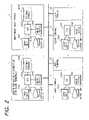
- FIG. 2is a hardware and network constitution for realizing the system constitution of the present invention.
- FIG. 3is a table constitution of a control table of clerk terminal connection.
- FIG. 4is a table constitution of a control table of priority connection of clerk terminal.
- FIG. 5is a table constitution of a control table lobby terminal connection.
- FIG. 6is a table constitution of a connective table to clerk terminal (call instruction).
- FIG. 7is a table constitution of a display table of clerk terminal codes able to connect to lobby terminals.
- FIG. 8is a table constitution of a selective table of clerk terminal able to connect to lobby terminal.
- FIG. 10is a table constitution of a control table of a connection with clerk terminal.
- FIG. 11is a table constitution of a completion table of a connection with clerk terminal.
- FIG. 12is a table constitution of a supplemental table of consultative information.
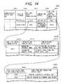
- FIG. 14is a table constitution of a consultative reply database.
- FIG. 15is a table constitution of a database of clerk terminal codes able to connect to lobby terminals.
- FIG. 16is a flow chart showing an embodiment of the present invention mostly with a process at a lobby terminal.
- FIG. 17is a detailed drawing of Step 100 .
- FIG. 18is a detailed drawing of Step 110 .
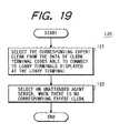
- FIG. 19is a detailed drawing of Step 120 .
- FIG. 20is a detailed drawing of Step 180 .
- FIG. 21is a detailed drawing of Step 190 .
- FIG. 22is a detailed drawing of Step 210 .
- FIG. 23is a flow chart showing an embodiment of the present invention mostly with a process in a clerk terminal.
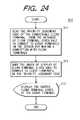
- FIG. 24is a detailed drawing of Step 310 .
- FIG. 25is a time chart of an actual example of taking over from an unattended agent server to a clerk terminal.
- FIG. 26is an example of a display screen from an output unit in a lobby terminal of the present invention when an expert clerk is called.
- a plurality of lobby terminals 2 for use by a user when requesting consultationa plurality of clerk terminals 4 used by a special expert clerk, a server for making a connection with clerk terminals 1 for controlling the connective status of the clerk terminals 4 in a uniform manner when the lobby terminals 2 are connected to the clerk terminals 4 , and an unattended agent server 3 for corresponding to an inquiry from the user when there is no expert clerk who can correspond to a consultation from the lobby terminals 2 are connected via a network.
- the server for making a connection with clerk terminals 1has a database 14 of clerk terminal codes able to connect to lobby terminals for controlling information on a clerk terminal which is able to connect in a uniform manner and performs a control function 11 of clerk terminal connection for selecting a connectable expert clerk using data stored in the database 14 of clerk terminal codes able to connect to lobby terminals, a control function 12 of priority connection of clerk terminal for deciding the connection priority to the lobby terminals 2 according to the past consulting frequency of an expert clerk, and a control function 13 of lobby terminal connection for controlling the lobby terminals 2 .
- the unattended agent server 3has a consultative reply database 33 storing the past consultative reply data for an inquiry of a user from the connected lobby terminal 2 and performs a supplemental function 31 of consultative information for supplying information corresponding to the inquiry detail to the lobby terminal 2 and a store function 32 of consultative inquiry and replay data for inquiring so as to take over the previous corresponding process and to store reply data when the terminal is changed to the clerk terminal 4 during correspondence with the consultation from the lobby terminal 2 .
- the clerk terminals 4perform a register function 41 of clerk terminal code able to connect to server for sending information that an expert clerk is able to connect to the server 1 for making a connection with clerk terminals 1 for controlling the plurality of clerk terminals 4 in a uniform manner, a control function 42 of a connection with clerk terminal for controlling (n) after connection with the lobby terminals 2 and controlling taking over of consultation from the unattended agent server 3 , and a completion function 43 of a connection with clerk terminal for breaking the connection with the lobby terminals 2 after the consultation ends and newly sending information that connection is able from the lobby terminals 2 to the server for making a connection (m) with clerk terminals 1 .
- FIG. 2shows a hardware constitution for realizing the process shown in FIG. 1 .
- the server 1 for making a connection with clerk terminals, a plurality of lobby terminals 2 and 2 a, the unattended agent server 3 , and a plurality of clerk terminals 4 and 4 aare connected to each other via a network such as Ethernet.
- the server 1 for making a connection with clerk terminalscomprises an input unit 1001 , an output unit 1002 , a CPU 1003 for executing the process shown in FIG. 1 , a main device 1004 for temporarily preserving a processing program and data in the table, and an external storage 1005 for storing a database.
- the lobby terminal 2comprises an input unit 2001 , an output unit 2002 , a CPU 2003 for executing a process, and a main device 2004 .
- the unattended agent server 3comprises an input unit 3001 , an output unit 3002 , a CPU 3003 , a main device 3004 , and an external storage 3005 same as with the server 1 for making a connection with clerk terminals mentioned above.
- the clerk terminal 4comprises an input unit 4001 , an output unit 4002 , a CPU 4003 , and a main device 4004 same as with the lobby terminal 2 mentioned above.
- FIG. 1a table for performing the process in each terminal (server included) is shown in FIG. 1 and the table constitution of the database 14 of clerk terminal codes able to connect to lobby terminals and of the consultative reply database 33 will be described.
- FIG. 3a control table of clerk terminal connection 1100 for the control function 11 of clerk terminal connection in the server for making a connection with clerk terminals 1 shown in FIG. 1 is shown in FIG. 3 .
- the control table of clerk terminal connection 1100 shown in FIG. 3comprises an expert clerk code field 1101 for storing an expert clerk code corresponding to a user, an area code field 1102 for storing an area code where an expert clerk exists, a station code field 1103 for storing a station code to which an expert clerk belongs, a terminal ID code field for storing the terminal ID of the clerk terminal 4 , a consulting frequency field 1105 while the clerk terminal connects server for storing the consulting frequency while the clerk terminal connects to server in the clerk terminal 4 by an expert clerk, and a connective status code field 1106 for storing the code corresponding to the connective status of the clerk terminal 4 .
- the control table 1200 of priority connection of clerk terminal shown in FIG. 4comprises an expert clerk field 1201 for storing the expert clerk code stored in the expert clerk code field 1101 shown in FIG. 3 , a login time field 1202 for storing a login time of an expert clerk from the clerk terminal 4 , a consulting frequency field 1203 while the clerk terminal connects server for storing the consulting frequency data stored in the consulting frequency field while the clerk terminal connects server 1105 shown in FIG. 3 , a station code field 1204 for storing the station code stored in the station code field 1103 shown in FIG. 3 , and a priority judgment code field 1205 for storing a clerk terminal priority code of a connectable expert clerk.
- the control table of lobby terminal connection 1300 shown in FIG. 5comprises a lobby terminal ID code field 1301 for storing a lobby terminal ID code to be connected, a lobby terminal status field 1302 for storing the status of the lobby terminal in the connective status, a selected expert clerk code field 1303 for storing an expert clerk code corresponding to an expert clerk selected from the lobby terminal, a consulting detail field 1304 for storing a consulting detail after consultation start, and a consulting time field 1305 for storing a consulting time after consultation start.
- FIG. 6a processing table 2100 of clerk terminal for the connective function 21 to clerk terminal (call function) in the lobby terminal 2 shown in FIG. 1 is shown in FIG. 6 .
- the processing table 2100 of clerk terminal shown in FIG. 6comprises a lobby terminal ID code field 2101 for storing the corresponding lobby terminal ID code and a lobby terminal status field 2102 for storing the connective status of the lobby terminal.
- FIG. 7a display table 2200 of clerk terminal codes able to connect to lobby terminals for the display function 22 of clerk terminal codes able to connect to lobby terminals in the lobby terminal 2 is shown in FIG. 7 .
- the display table 2200 of clerk terminal codes able to connect to lobby terminals shown in FIG. 7comprises a list number field 2201 for storing numbers in the listing order, an expert clerk code field 2202 for storing a connectable expert clerk code, an area code field 2203 for storing the area code of each expert clerk, a station code field 2204 for storing the station code of each expert clerk, and a terminal ID code field 2205 for storing the terminal ID code of the clerk terminal 4 corresponding to each expert clerk.
- FIG. 8a selective table 2300 of clerk terminal able to connect to lobby terminal for the selective function 23 of clerk terminal able to connect to lobby terminal in the lobby terminal 2 is shown in FIG. 8 .
- the selective table 2300 of clerk terminal able to connect to lobby terminal shown in FIG. 8comprises a list number field 2301 for storing a selected list number, an expert clerk code field 2302 for storing an expert clerk code, and a terminal ID code field 2303 for storing the terminal ID code of the clerk terminal 4 corresponding to each expert clerk.
- FIG. 9a register table 4100 of clerk terminal code able to connect to server for the register function of clerk terminal code cable to connect co server in the clerk terminal 4 shown in FIG. 1 is shown in FIG. 9 .
- the register table 4100 of clerk terminal code able to connect to server shown in FIG. 9comprises an expert clerk code field 4101 for storing an expert clerk code using the clerk terminal, an area code field 4102 for storina the area code corresponding to the expert clerk stored in the expert clerk code field 4101 , a station code field 4103 for also storing the station code corresponding to an expert clerk, a terminal ID code field 4104 for storing the terminal ID code of the clerk terminal, and a login time field 4105 for storing the time logged in the clerk terminal by an expert clerk.
- the control table 4200 of a connection with clerk terminal shown in FIG. 10comprises a lobby terminal ID code field 4201 for storing the ID code of the connected lobby terminal 2 , a lobby terminal status field 4202 for storing the lobby terminal status of the lobby terminal 2 , a consulting detail field 4203 for storing a consulting detail from a user, and a code field 4204 for taking over the consulting detail for storing a code for taking over the consulting detail from the unattended agent server 3 shown in FIG. 1 .
- the completion table 4300 of a connection with clerk terminal for the completion function 43 of a connection with clerk terminal in the clerk terminal 4is shown in FIG. 11 .
- the completion table 4300 of a connection with clerk terminal shown in FIG. 11comprises an expert clerk code field 4301 for storing the expert clerk code stored in the expert clerk code field 4101 shown in FIG. 9 , a terminal ID code field 4302 for storing the terminal ID code stored in the terminal ID code field 4104 , a logout time field 4303 for storing the time logged out from the clerk terminal by an expert clerk, and a judgment code field for end of consultation 4304 for storing a code for judging the end of consultation.
- the supplemental table 3100 of consultative information shown in FIG. 12comprises a lobby terminal ID code field 3101 for storing the lobby terminal ID code of the connected lobby terminal 2 , a lobby terminal status field 3102 for storing the connective status of the lobby terminal, a consulting detail field 3103 for storing a consulting detail, a code field 3104 for taking over the consulting detail for storing a code for taking over to the clerk terminal (corresponding expert clerk), and a Q&A code field 3105 about consultation for storing a code corresponding to data of inquiry information from the lobby terminal 2 and reply data which are stored.
- FIG. 13a store table 3200 of consultative inquiry and reply data for the store function 32 of consultative inquiry and reply data in the unattended agent server 3 is shown in FIG. 13 .
- the store table 3200 of consultative inquiry and reply data shown in FIG. 13comprises a Q&A code field about consultation 3201 for storing the Q&A code about consultation stored in the Q&A code field 3105 about consultation shown in FIG.
- a consulting detail field 3202for storing the consulting detail stored in the consulting detail field 3103
- a lobby terminal ID code field 3203for storing the lobby terminal ID code stored in the lobby terminal ID code field 3101
- an expert clerk code field 3204for storing the expert clerk code of taking over the consulting detail
- a data store day field 3205for storing the data store day that the Q&A code about consultation i@ stored.
- the table 3300 shown in FIG. 14is a control table of consultative reply data and comprises a consultative reply data No. field 3301 storing the consultative reply data number, a data store day field 3302 storing the data store day, a Q&A code field 3303 about consultation storing a Q&A code about consultation, a consulting detail field 3304 storing a consulting detail, and a code field 3305 for taking over the consulting detail storing a code for taking over the consulting detail.
- a table 33100is a table storing detailed data corresponding to a Q&A code about consultation and comprises a Q&A code field 33101 about consultation storing a Q&A code about consultation, a consultation inquiry data field 33102 storing consultation inquiry data from the lobby terminal 2 , and a consultation reply data field 33103 storing consultation reply data to reply to the lobby terminal 2 from the unattended agent server 3 .
- a table 33200is a table storing detailed data corresponding to a code for taking over the consulting detail and comprises a code field 33201 for taking over the consulting detail storing a code for taking over the consulting detail and a data field 33202 for taking over the consulting detail storing real data for taking over the consulting detail.
- the table 1400 shown in FIG. 15is a table for controlling the connective status of the clerk terminal and comprises a number field 1401 of database of clerk terminal code able to connect to lobby terminal storing a number of database of clerk terminal code able to connect to lobby terminal, an expert clerk code field 1402 storing a connectable expert clerk code, an area code field 1403 storing an area code, a station code field 1404 storing a station code, a terminal ID code field 1405 storing the terminal ID code of the clerk terminal 4 , a consulting frequency field 1406 while the clerk terminal connects server in which the consulting frequency while the clerk terminal connects server is stored by an expert clerk, and a connective status code field 1407 storing the connective status code of the clerk terminal 4 .
- a table 14100is a table storing the priority connection of clerk terminal and comprises a number field 14101 of priority connection of clerk terminal storing the number of priority connection of clerk terminal, an expert clerk code field 14102 storing an expert clerk code, a consulting frequency field 14103 while the clerk terminal connects server for storing the consulting frequency while the clerk terminal connects server, and a priority judgment code field 14104 for storing a priority judgment code.
- a table 14210is a table storing an expert clerk name corresponding to an expert clerk code and comprises an ex-pert clerk code field 14211 storing an expert clerk code and an expert clerk name field 14212 storing the corresponding expert clerk name.
- a table 14220comprises an area code field 14221 storing an area code and an area name field 14222 storing the corresponding area name.
- a table 14230comprises a station code field 14231 storing a station code and a station name field 14232 storing the corresponding station name.
- Step 100an expert clerk is called by the connective function to clerk terminal (call instruction) 21 of the lobby terminal 2 shown in FIG. 1 .
- the clerk terminal code able to connect to the lobby terminal taken out from the server for making a connection with clerk terminals 1is displayed on the lobby terminal 2 .
- Detailed processing at Step 110will be described later by referring to FIG. 18 .
- Step 120an expert clerk able to connect is selected at the lobby terminal 2 .
- Detailed processing at Step 120will be described later by referring to FIG. 19 .
- Step 130it is decided whether the terminal selected at the lobby terminal 2 is the clerk terminal 4 or the unattended agent server 3 .
- the area codes 2203 of the table 2200 shown in FIG. 7are all blank, no expert clerk is registered. Therefore, the unattended agent server 3 is selected.
- a specific clerk terminal 4is selected, the program goes to Step 140 .
- Step 140the expert clerk code ( 1101 ) of the table 1100 shown in FIG. 3 corresponding to the expert clerk selected by the lobby terminal 2 shown in FIG. 1 at Step 120 is obtained and connection with the clerk terminal 4 corresponding to the terminal ID code ( 1104 ) corresponding to the obtained expert clerk code is requested to the control function 12 of clerk terminal connection of the server 1 for making a connection with clerk terminals.
- Step 150communication is connected between the clerk terminal 4 whose connection is requested at Step 140 and the called lobby terminal 2 .
- Step 160remote consultation is carried out between the connected lobby terminal 2 and the clerk terminal 4 using functions of video conference, display screen shared, etc.
- Step 170 ( m )after end of the remote consultation, the communication between the connected lobby terminal 2 and the clerk terminal 4 is disconnected and the lobby terminal 2 is put into the state that it can correspond to another inquiry.
- Step 180communication is connected between the lobby terminal 2 and the unattended agent server 3 . Detailed processing at Step 180 will be described later by referring to FIG. 20 .
- Step 190the past reply to the inquiry to the lobby terminal 2 from the user is searched from the consultative reply database 33 by the connected unattended agent server 3 and information is supplied to the lobby terminal 2 via the supplemental function 31 of consultative information.
- Detailed processing at Step 190will be described later by referring to FIG. 21 .
- Step 200it is decided whether the expert clerk corresponding to the consulting detail is made connectable on the basis of the code setting status of the area code 2203 of the table 2200 shown in FIG. 7 during information supply from the unattended agent server 3 . As a result of decision, when the expert clerk is unconnectable, the program returns to Step 190 .
- Step 210the program goes to Step 210 .
- the consultation endsthe communication between the lobby terminal 2 and the unattended agent server 3 is disconnected.
- Step 210the inquiry data inputted by the user via the lobby terminal 2 and the consultative reply data sent to the lobby terminal from the unattended agent server 3 are sent (taking over the consulting detail) to the clerk terminal 4 which is changed in connection. Detailed processing at Step 210 will be described later by referring to FIG. 22 .
- Step 100will be explained in detail by referring to FIG. 17 .
- the lobby terminal ID code stored in the lobby terminal ID code field 2101 of the connective table 2100 to clerk terminal shown in FIG. 6is sent to the control function 13 of lobby terminal connection of the server 1 for making a connection with clerk terminals by the connective function to clerk terminal (call instruction) 21 of the lobby terminal 2 ( a ) and stored in the lobby terminal ID code field 1301 of the control table of lobby terminal connection 1300 shown in FIG. 5 .
- Step 192the connective status of the lobby terminal stored in the lobby terminal status field 2102 of the connective table 2100 to clerk terminal shown in FIG. 6 is sent to the control function of lobby terminal connection 13 of the server for making a connection with clerk terminals 1 and stored in the lobby terminal status field 1302 of the control table 1300 of lobby terminal connection shown in FIG. 5 .
- Step 110will be explained in detail by referring to FIG. 18 .
- the control function 11 of clerk terminal connection of the server 1 for making a connection with clerk terminals shown in FIG. 1decides a connectable expert clerk from the database 14 of clerk terminal codes able to connect to lobby terminals by the connective status code, reads the expert clerk code, area code, station code, terminal ID code of the clerk terminal, consulting frequency while the clerk terminal connects server, and connective status code, and stores them in the control table of clerk terminal connection 1100 shown in FIG. 3 .
- the control function 11 of clerk terminal connectionsends data such as the connectable expert clerk read at Step 111 to the display function 22 of clerk terminal codes able to connect to lobby terminals of the lobby terminal 2 shown in FIG. 1 and stores the expert clerk code, area code, station code, and terminal ID code of the clerk terminal in the display table 2200 of clerk terminal codes able to connect to lobby terminals shown in FIG. 7 in the sending order (e).
- the control function 11 of clerk terminal connectionoutputs and displays the list of the connectable expert clerk (area name, station, expert clerk name) stored in the display table 2200 of clerk terminal codes able to connect to lobby terminals at Step 112 from the output unit 2002 in the lobby terminal 2 shown in FIG. 2 .
- the correspondence between the expert clerk code, area code, and station code and the concrete expert clerk name, area name, and station nameis converted by referring to the database tables 14210 , 14220 and 14230 of clerk terminal codes able to connect to lobby terminals shown in FIG. 15 .
- Step 120will be explained in detail by referring to FIG. 19 .
- the lobby terminal 2 shown in FIG. 1selects an expert clerk corresponding to the consulting detail of the user from the list of connectable expert clerks displayed at Step 110 shown in FIG. 16 by the selective function 23 of clerk terminal able to connect to lobby terminal and stores the selected list number, expert clerk code, and terminal ID code in the selective table 2300 of clerk terminal able to connect to lobby terminal shown in FIG. 8 .
- Step 122when there is no expert clerk corresponding to the consulting detail of the user at Step 121 , the lobby terminal 2 selects tiae unattended agent server 3 shown in FIG. 1 and stores a terminal ID code corresponding to the unattended agent server 3 in the terminal ID code field 2303 of the selective table 2300 of clerk terminal able to connect to lobby terminal.
- Step 180will be explained in detail by referring to FIG. 20 .
- the inquiry detail of the user from the lobby terminal 2 shown in FIG. 1is sent to the unattended agent server 3 ( f ) and the supplemental function 31 of Consultative information decides the consulting detail and stores it in the consulting detail field 3103 of the supplemental table of consultative information 3100 shown in FIG. 12( g ).
- the supplemental function 31 of consultative informationsends the inquiry data on the basis of the consulting detail decided at Step 181 to the 5 unattended agent server 3 ( f )
- the supplemental function 31 of consultative informationadds the code for the sent data and stores it in the Q&A code field about consultation 3105 of the information supply table shown in FIG. 12( i ).
- the supplemental function 31 of consultative informationstores the Q&A data about consultation (inquiry data) in the store table of consultative inquiry and reply data 3200 shown in FIG.
- Step 190will be explained in detail by referring to FIG. 21 .
- the supplemental function 31 of consultative information of the unattended agent server 3 shown in FIG. 1stores the past consultative reply data corresponding to the consulting detail decided at Step 180 in the consultation reply data field 33103 corresponding to the Q&A code field about consultation 33101 corresponding to the inquiry of the consultative reply database 33 .
- the supplemental function 31 of consultative informationsends the consultative reply data stored at Step 191 to the lobby terminal 2 as a reply to the inquiry from the lobby terminal 2 ( i )
- the supplemental function 31 of consultative informationstores it in the table of taking over the consulting detail 33200 of the consultative reply database 33 as data of taking over the consulting detail.
- the supplemental function of consultative information 31outputs and displays the consultative reply data sent to the lobby terminal 2 at Step 192 from the output unit 2002 shown in FIG. 2 .
- Step 210will be explained in detail by referring to FIG. 22 .
- the clerk terminal 4 corresponding to the consulting detail of the useris made connectable by the server 1 for making a connection with clerk terminals controlling the connectable clerk terminals 4 in a uniform manner when data is exchanged between the lobby terminal 2 and the unattended agent server 3 shown in FIG. 1 , the connecting unattended agent server 3 is changed to the connectable clerk terminal 4 .
- the code for taking over the consultative detail corresponding to the data for taking over the consulting detail (the table 33200 ) stored in the consultative reply database 33is sent to the clerk terminal to be changed to from the unattended agent server 3 by the supplemental function 31 ( k ) of consultative information and stored in the code field for taking over the consulting detail 4204 of the control table of a connection with clerk terminal 4200 shown in FIG. 10 .
- the data for taking over the consulting detail corresponding to the code for taking over the consulting detail stored at Step 212is read from the table 33200 of the consultative reply database 33 of the unattended agent server 3 and outputted and displayed on the output unit 4002 of the clerk terminal 4 shown in FIG. 2 .
- the register function 41 of clerk terminal code able to connect to server of the clerk terminal 4 shown in FIG. 1inputs an expert clerk code from the input unit 4001 of the clerk terminal 4 shown in FIG. 2 and stores the login time in the expert clerk code field 4101 and the login time field 4105 of the register table of clerk terminal code able to connect to server 4100 shown in FIG. 9 .
- the expert clerk code inputted at Step 300 and the logged-in area code, station code, and terminal ID code from the clerk terminal 4are sent to the server 1 ( l ) for making a connection with clerk terminals. Detailed processing at Step 310 will be described later by referring to FIG. 24 .
- Step 320the clerk terminal 4 decides whether there is a connection from the lobby terminal 2 or the unattended agent server 3 on the basis of the lobby terminal ID code 4201 in the table 4200 shown in FIG. 10 .
- the programgoes to Step 330 .
- the decision at Step 320is repeated until connected from the lobby terminal 2 .
- the clerk terminal 4When the clerk terminal 4 relating to the consulting detail becomes connectable after the process ends, the clerk terminal 4 takes over exchange information with the lobby terminal 2 from the unattended agent server 3 and sends the reply data asynchronously using the lobby terminal 2 or another communication means such as telephone to the user or FAX.
- the control function 42 of a connection with clerk terminal of the clerk terminal 4 shown in FIG. 1decides whether the connected terminal is the lobby terminal 2 or the unattended agent server 3 on the basis of the lobby terminal status 4202 in the table 4200 shown in FIG. 10 .
- the programgoes to Step 340 .
- Step 360the program goes to Step 360 .
- Step 340the user and the expert clerk carry out remote consultation with each other using the functions of video conference, display screen shared, etc. via the connected lobby terminal 2 .
- Step 350after the consultation is over, the logout time is stored in the logout time field 4303 in the completion table 4300 of a connection with clerk terminal shown in FIG. 11 by the completion function 43 of a connection with clerk terminal at the clerk terminal 4 , and the judgment code for end of consultation (a connectable code is stored) is stored in the judgment code field for end of consultation 4304 , and the communication with the connected lobby terminal 2 is disconnected.
- the judgment code for end of consultationis sent to the control table of clerk terminal connection 1100 of the server 1 for making a connection with clerk terminals shown in FIG.
- Step 360the clerk terminal 4 receives exchange with the lobby terminal 2 from the unattended agent server 3 as data for taking over the consulting detail.
- Step 370the data for taking over the consulting detail taken over from the unattended agent server 3 is displayed on the clerk terminal 4 .
- Detailed processing at Steps 360 and 370will be described later by referring to FIGS. 21 and 22 , so that it is omitted here.
- Step 310 shown in FIG. 23will be described in detail by referring to FIG. 24 .
- the priority judgment code stored in the priority judgment code field 14104 of the connectable clerk terminal 4is read by the control function 12 of priority connection of clerk terminal of the server for making a connection with clerk terminals 1 shown in FIG. 1 from the table 14100 of the database 14 of clerk terminal codes able to connect to lobby terminals.
- the order of display of clerk terminal codes able to connect to lobby terminalsis sorted in the order of descending priorities (in the order of ascending consulting frequencies) on the basis of the priority judgment code when an expert clerk code correspondable to the same consulting detail is displayed at the lobby terminal 2 .
- the sorted resultis stored in the control table 1200 of priority connection of clerk terminal shown in FIG. 4 so that the clerk terminal codes are displayed at the lobby terminal 2 in the order sorted at Step 312 .
- FIG. 25is a time chart showing the operating status of each terminal (the server 1 for making a connection with clerk terminals, the unattended agent server 3 , the lobby terminal 2 , the clerk terminal 4 ).
- the lobby terminal 2starts the server 1 for making a connection with clerk terminals via the connective function 21 to clerk terminal (call instruction) shown in FIG. 1 ( 550 ).
- the server 1 for making a connection with clerk terminalsreceives a request from the lobby terminal via the control function of lobby terminal connection 13 and the control function 11 of clerk terminal connection sends display data of clerk terminal codes able to connect to lobby terminals to the lobby terminal 2 at the time of request ( 510 ).
- the received lobby terminal 2selects the unattended agent server 3 .
- the server 1 for making a connection with clerk terminalsconnects the selected unattended agent server 3 and the lobby terminal 2 .
- the unattended agent server 3 and the lobby terminal 2are connected and the consultation starts ( 540 , 560 ) (t 1 ).
- the unattended agent server 3retrieves the past reply data corresponding to the consulting detail from the consultative reply database 33 for the inquiry from the lobby terminal 2 and sends a reply to the lobby terminal 2 via the supplemental function 31 of consultative information.
- the unattended agent server 3stores data for taking over the consulting detail comprising an inquiry from the lobby terminal 2 and reply data from the unattended agent server 3 in the consultative reply database 33 by the store function 32 of consultative inquiry and replay data (the tables 33100 , 33200 ).
- the server 1 for making a connection with clerk terminalsconfirms whether there is a connectable clerk terminal 4 corresponding to the consulting detail ( 520 ).
- the unattended agent server 3is changed to the clerk terminal 4 by the server 1 for making a connection with clerk terminals controlling the status of clerk terminals in a uniform manner.
- the data for taking over the consulting detail stored in the consultative reply database 33is sent to the clerk terminal 4 via the store function 32 of consultative inquiry and replay data of the unattended agent server 3 .
- the lobby terminal 2 and the clerk terminal 4are connected and the consultation starts (t 2 ).
- the connected expert clerklooks at the connection information from the unattended agent server 3 and continues the consultation with the user of the lobby terminal.
- Information exchange between the lobby terminal 2 and the clerk terminal 4is carried out by using the functions such as video conference and display screen shared ( 570 , 580 ).
- the clerk terminal 4disconnects the communication with the lobby terminal (t 3 ) and sends the information that it is connectable to another clerk terminal or the unattended agent server 3 to the server 1 for making a connection with clerk terminals by the completion function 43 of a connection with clerk terminal of the clerk terminal 4 .
- the server 1 for making a connection with clerk terminalschanges the connective status of the clerk terminal from “connected” ( 530 ) to “connectable status”, displays the clerk terminal codes at the called lobby terminal, and waits for connection from the lobby terminal ( 590 ).
- the explanation of an actual examination of the connection process using the time chart showing the operating status of each terminalends.
- FIGS. 26 and 27display screen examples of the output unit 2002 of the lobby terminal 2 shown in FIG. 2 are shown in FIGS. 26 and 27 .
- a display screen 700 shown in FIG. 26comprises a “clerk call” button 710 for calling a connectable expert clerk, a video conference screen 720 displayed when a clerk terminal is connected, and an operating area on display screen 730 .
- FIG. 27shows a screen layout when the display function 22 of clerk terminal codes able to connect to lobby terminals receives data from the server 1 for making a connection with clerk terminals and displays the clerk terminal codes able to connect to lobby terminals ( 740 ).
- the display screen 740comprises the video conference screen 720 , the operating area on display screen 730 , and a display screen of clerk terminal codes able to connect to lobby terminals 750 .
- the present inventionto carry out a remote consultation by a user from the lobby terminal, it is possible to display connectable clerk terminal codes at the lobby terminal and select an expert clerk corresponding to a consultation from the user.
- the expert clerk corresponding to the consulting detail of the useris not connectable, it is possible to connect to the unattended agent server first and supply the past consultative reply information regarding the consulting detail to the lobby terminal from the unattended agent server.
- the server for making a connection with clerk terminalschanges the unattended agent server to the clerk terminal halfway.
- the clerk terminalis changed, the exchange with the lobby terminal by the unattended agent server is stored and taken over by the clerk terminal.
- the unattended agent servercorresponds to the consultation and when the correspondable expert clerk enters the connectable state.
- the unattended agent servertakes over the consulting detail and changes the clerk terminal, so that the consultation disabled state from the user can be avoided.
- the consulting detail from the user which is stored by the unattended agent serveris taken over by the clerk terminal and the expert clerk can reply by using a communication means such as telephone and FAX.
Landscapes
- Engineering & Computer Science (AREA)
- Signal Processing (AREA)
- General Engineering & Computer Science (AREA)
- Multimedia (AREA)
- Computer Networks & Wireless Communication (AREA)
- Business, Economics & Management (AREA)
- Marketing (AREA)
- Computer And Data Communications (AREA)
- Management, Administration, Business Operations System, And Electronic Commerce (AREA)
- Financial Or Insurance-Related Operations Such As Payment And Settlement (AREA)
Abstract
Description
Claims (9)
Priority Applications (1)
| Application Number | Priority Date | Filing Date | Title |
|---|---|---|---|
| US09/846,615US7031997B2 (en) | 1996-09-20 | 2001-05-02 | Method and apparatus for connecting terminals in a remote consulting system |
Applications Claiming Priority (4)
| Application Number | Priority Date | Filing Date | Title |
|---|---|---|---|
| JP24960996AJPH1097571A (en) | 1996-09-20 | 1996-09-20 | Consultation terminal connection method |
| JP8-249609 | 1996-09-20 | ||
| US08/934,063US6256661B1 (en) | 1996-09-20 | 1997-09-19 | Method and apparatus for connecting terminals in a remote consulting system |
| US09/846,615US7031997B2 (en) | 1996-09-20 | 2001-05-02 | Method and apparatus for connecting terminals in a remote consulting system |
Related Parent Applications (1)
| Application Number | Title | Priority Date | Filing Date |
|---|---|---|---|
| US08/934,063ContinuationUS6256661B1 (en) | 1996-09-20 | 1997-09-19 | Method and apparatus for connecting terminals in a remote consulting system |
Publications (2)
| Publication Number | Publication Date |
|---|---|
| US20010032242A1 US20010032242A1 (en) | 2001-10-18 |
| US7031997B2true US7031997B2 (en) | 2006-04-18 |
Family
ID=17195580
Family Applications (2)
| Application Number | Title | Priority Date | Filing Date |
|---|---|---|---|
| US08/934,063Expired - LifetimeUS6256661B1 (en) | 1996-09-20 | 1997-09-19 | Method and apparatus for connecting terminals in a remote consulting system |
| US09/846,615Expired - Fee RelatedUS7031997B2 (en) | 1996-09-20 | 2001-05-02 | Method and apparatus for connecting terminals in a remote consulting system |
Family Applications Before (1)
| Application Number | Title | Priority Date | Filing Date |
|---|---|---|---|
| US08/934,063Expired - LifetimeUS6256661B1 (en) | 1996-09-20 | 1997-09-19 | Method and apparatus for connecting terminals in a remote consulting system |
Country Status (3)
| Country | Link |
|---|---|
| US (2) | US6256661B1 (en) |
| JP (1) | JPH1097571A (en) |
| GB (1) | GB2317473B (en) |
Families Citing this family (30)
| Publication number | Priority date | Publication date | Assignee | Title |
|---|---|---|---|---|
| JPH1097571A (en)* | 1996-09-20 | 1998-04-14 | Hitachi Ltd | Consultation terminal connection method |
| US6601087B1 (en)* | 1998-11-18 | 2003-07-29 | Webex Communications, Inc. | Instant document sharing |
| US7505974B2 (en)* | 1999-02-12 | 2009-03-17 | Gropper Robert L | Auto update utility for digital address books |
| US6883000B1 (en)* | 1999-02-12 | 2005-04-19 | Robert L. Gropper | Business card and contact management system |
| US6763371B1 (en)* | 1999-05-10 | 2004-07-13 | Telefonaktiebolaget Lm Ericsson (Publ) | Method and apparatus for collaborative communication in a communication network |
| JP3487245B2 (en)* | 1999-10-27 | 2004-01-13 | Kddi株式会社 | COMMUNICATION CONNECTION METHOD, EXCHANGE NETWORK CONTROL DEVICE, AND SYSTEM WITHOUT SPECIFYING ENDING TERMINAL |
| US20020029350A1 (en)* | 2000-02-11 | 2002-03-07 | Cooper Robin Ross | Web based human services conferencing network |
| JP4911809B2 (en)* | 2000-06-16 | 2012-04-04 | 沖電気工業株式会社 | Customer guidance system |
| JP3735018B2 (en)* | 2000-08-02 | 2006-01-11 | 日立オムロンターミナルソリューションズ株式会社 | Remote consultation terminal system |
| US7593751B2 (en)* | 2000-09-18 | 2009-09-22 | Field Data Management Solutions, Llc | Conducting field operations using handheld data management devices |
| GB2369462A (en)* | 2000-11-22 | 2002-05-29 | Tenzen Plc | A method and system for brokering a communication session between a manufacturing machine and a support service |
| US20030167176A1 (en)* | 2001-03-22 | 2003-09-04 | Knudson Natalie A. | System and method for greeting a visitor |
| JP2003044583A (en)* | 2001-08-01 | 2003-02-14 | Tadashi Kaneko | System for remote psychiatric analysis by operation history |
| JP2003187063A (en)* | 2001-12-13 | 2003-07-04 | Oki Electric Ind Co Ltd | Inquiry accepting system |
| KR100402094B1 (en)* | 2002-11-22 | 2003-10-17 | 알서포트 주식회사 | Remote control system using web and icon |
| US20040236706A1 (en)* | 2003-04-30 | 2004-11-25 | Fitch James Chester | Automated machinery lubrication service and maintenance planning system |
| US8682969B1 (en)* | 2005-10-07 | 2014-03-25 | On24, Inc. | Framed event system and method |
| US20070136342A1 (en)* | 2005-12-13 | 2007-06-14 | Sap Ag | Processing a user inquiry |
| JP5103126B2 (en)* | 2007-10-02 | 2012-12-19 | ローレルバンクマシン株式会社 | Reception number ticketing system |
| US9892028B1 (en) | 2008-05-16 | 2018-02-13 | On24, Inc. | System and method for debugging of webcasting applications during live events |
| US10430491B1 (en) | 2008-05-30 | 2019-10-01 | On24, Inc. | System and method for communication between rich internet applications |
| US8629755B2 (en) | 2008-08-15 | 2014-01-14 | Mohammed Hashim-Waris | Visitor management systems and methods |
| US11438410B2 (en) | 2010-04-07 | 2022-09-06 | On24, Inc. | Communication console with component aggregation |
| US8706812B2 (en) | 2010-04-07 | 2014-04-22 | On24, Inc. | Communication console with component aggregation |
| JP5003841B2 (en)* | 2011-12-12 | 2012-08-15 | 沖電気工業株式会社 | Customer guidance system |
| US11429781B1 (en) | 2013-10-22 | 2022-08-30 | On24, Inc. | System and method of annotating presentation timeline with questions, comments and notes using simple user inputs in mobile devices |
| US10785325B1 (en) | 2014-09-03 | 2020-09-22 | On24, Inc. | Audience binning system and method for webcasting and on-line presentations |
| US11188822B2 (en) | 2017-10-05 | 2021-11-30 | On24, Inc. | Attendee engagement determining system and method |
| US11281723B2 (en) | 2017-10-05 | 2022-03-22 | On24, Inc. | Widget recommendation for an online event using co-occurrence matrix |
| JP7581741B2 (en)* | 2019-10-23 | 2024-11-13 | 株式会社リコー | COMMUNICATION TERMINAL, COMMUNICATION SYSTEM, COMMUNICATION METHOD, AND PROGRAM |
Citations (60)
| Publication number | Priority date | Publication date | Assignee | Title |
|---|---|---|---|---|
| US4700340A (en)* | 1986-05-20 | 1987-10-13 | American Telephone And Telegraph Company, At&T Bell Laboratories | Method and apparatus for providing variable reliability in a telecommunication switching system |
| US4922519A (en) | 1986-05-07 | 1990-05-01 | American Telephone And Telegraph Company | Automated operator assistance calls with voice processing |
| US4939771A (en) | 1989-09-20 | 1990-07-03 | At&T Bell Laboratories | Attendant-controlled call message delivery system and method |
| US4982344A (en)* | 1988-05-18 | 1991-01-01 | Xerox Corporation | Accelerating link creation |
| US5053956A (en) | 1985-06-17 | 1991-10-01 | Coats Viyella | Interactive system for retail transactions |
| US5138377A (en)* | 1991-05-23 | 1992-08-11 | Xerox Corporation | Internal expert system to aid in servicing |
| US5220674A (en)* | 1987-07-17 | 1993-06-15 | Digital Equipment Corporation | Local area print server for requesting and storing required resource data and forwarding printer status message to selected destination |
| US5311422A (en)* | 1990-06-28 | 1994-05-10 | The United States Of America As Represented By The Administrator Of The National Aeronautics And Space Administration | General purpose architecture for intelligent computer-aided training |
| US5317725A (en)* | 1991-03-12 | 1994-05-31 | Hewlett-Packard Company | Landmark data abstraction paradigm to diagnose data communication networks |
| JPH07168889A (en) | 1993-12-16 | 1995-07-04 | Hitachi Ltd | Reception management system |
| US5444615A (en)* | 1993-03-24 | 1995-08-22 | Engate Incorporated | Attorney terminal having outline preparation capabilities for managing trial proceeding |
| US5469206A (en) | 1992-05-27 | 1995-11-21 | Philips Electronics North America Corporation | System and method for automatically correlating user preferences with electronic shopping information |
| US5581753A (en) | 1994-09-28 | 1996-12-03 | Xerox Corporation | Method for providing session consistency guarantees |
| US5586175A (en) | 1993-10-15 | 1996-12-17 | Linkusa Corporation | Call-processing system and method |
| US5621884A (en)* | 1993-04-30 | 1997-04-15 | Quotron Systems, Inc. | Distributed data access system including a plurality of database access processors with one-for-N redundancy |
| US5633910A (en)* | 1994-09-13 | 1997-05-27 | Cohen; Kopel H. | Outpatient monitoring system |
| US5673253A (en) | 1996-02-29 | 1997-09-30 | Siemens Business Communication Systems | Dynamic allocation of telecommunications resources |
| US5703935A (en) | 1994-03-29 | 1997-12-30 | Mci Communications Corporation | Automated telephone operator services |
| US5713027A (en)* | 1994-05-26 | 1998-01-27 | Hitachi, Ltd. | Method and apparatus for controlling the shutdown of computer systems by using service utilization information and examining a dependency relationship between the computers |
| US5712978A (en)* | 1994-12-30 | 1998-01-27 | Lucent Technologies Inc. | System for control of remote processors |
| US5721817A (en) | 1987-11-20 | 1998-02-24 | Hitachi, Ltd. | Control method and apparatus for dynamically switching a logical session |
| US5724516A (en)* | 1995-09-06 | 1998-03-03 | International Business Machines Corporation | System for dynamically creating and retrieving formatted dump data by setting value in dump object indicating that the dump agent is to generate formatted dump data |
| US5729745A (en)* | 1994-11-14 | 1998-03-17 | Microsoft Corporation | Methods and apparatus for creating a base class for manipulating external data connections in a computer generated document |
| US5751965A (en)* | 1996-03-21 | 1998-05-12 | Cabletron System, Inc. | Network connection status monitor and display |
| US5751943A (en)* | 1993-01-27 | 1998-05-12 | Alcatel Network Systems, Inc. | Electronic work environment for a data processing system |
| US5758071A (en)* | 1996-07-12 | 1998-05-26 | Electronic Data Systems Corporation | Method and system for tracking the configuration of a computer coupled to a computer network |
| US5764914A (en) | 1993-12-15 | 1998-06-09 | Fujitsu Limited | Network system for connecting to a network node from terminal |
| US5764916A (en) | 1996-09-27 | 1998-06-09 | Ichat, Inc. | Method and apparatus for real time communication over a computer network |
| US5774669A (en)* | 1995-07-28 | 1998-06-30 | The United States Of America As Represented By The Administrator Of The National Aeronautics And Space Administration | Scalable hierarchical network management system for displaying network information in three dimensions |
| US5778377A (en)* | 1994-11-04 | 1998-07-07 | International Business Machines Corporation | Table driven graphical user interface |
| US5781703A (en)* | 1996-09-06 | 1998-07-14 | Candle Distributed Solutions, Inc. | Intelligent remote agent for computer performance monitoring |
| US5793365A (en) | 1996-01-02 | 1998-08-11 | Sun Microsystems, Inc. | System and method providing a computer user interface enabling access to distributed workgroup members |
| US5799151A (en) | 1994-04-04 | 1998-08-25 | Hoffer; Steven M. | Interactive electronic trade network and user interface |
| US5799273A (en)* | 1996-09-24 | 1998-08-25 | Allvoice Computing Plc | Automated proofreading using interface linking recognized words to their audio data while text is being changed |
| US5805823A (en) | 1996-01-30 | 1998-09-08 | Wayfarer Communications, Inc. | System and method for optimal multiplexed message aggregation between client applications in client-server networks |
| US5805786A (en) | 1996-07-23 | 1998-09-08 | International Business Machines Corporation | Recovery of a name server managing membership of a domain of processors in a distributed computing environment |
| US5812780A (en) | 1996-05-24 | 1998-09-22 | Microsoft Corporation | Method, system, and product for assessing a server application performance |
| US5819267A (en)* | 1995-06-30 | 1998-10-06 | Fujitsu Limited | Know-how management apparatus, and method |
| US5825856A (en) | 1994-03-31 | 1998-10-20 | Citibank, N.A. | Interactive voice response system for banking by telephone |
| US5862330A (en) | 1996-07-16 | 1999-01-19 | Lucent Technologies Inc. | Technique for obtaining and exchanging information on wolrd wide web |
| US5870721A (en) | 1993-08-27 | 1999-02-09 | Affinity Technology Group, Inc. | System and method for real time loan approval |
| US5903725A (en) | 1995-09-15 | 1999-05-11 | International Business Machines Corporation | Recoverable proxy object in an object oriented environment |
| US5909543A (en) | 1994-11-30 | 1999-06-01 | Canon Kabushiki Kaisha | Communication conference system and communication conference apparatus |
| US5915008A (en) | 1995-10-04 | 1999-06-22 | Bell Atlantic Network Services, Inc. | System and method for changing advanced intelligent network services from customer premises equipment |
| US5933412A (en) | 1994-10-17 | 1999-08-03 | Lucent Technologies Inc. | Parallel connection control |
| US5940614A (en)* | 1991-04-18 | 1999-08-17 | International Business Machines Corporation | Hypertext control method and apparatus for displaying help information in an interactive data processing system |
| US5944795A (en) | 1996-07-12 | 1999-08-31 | At&T Corp. | Client-server architecture using internet and guaranteed quality of service networks for accessing distributed media sources |
| US5958013A (en) | 1997-09-11 | 1999-09-28 | International Business Machines Corporation | Apparatus, methods and computer program products for conducting a persistent session with a host-based application |
| US5964837A (en)* | 1995-06-28 | 1999-10-12 | International Business Machines Corporation | Computer network management using dynamic switching between event-driven and polling type of monitoring from manager station |
| US5966531A (en)* | 1989-07-27 | 1999-10-12 | Reuters, Ltd. | Apparatus and method for providing decoupled data communications between software processes |
| US5995604A (en)* | 1997-06-20 | 1999-11-30 | Nortel Networks Corporation | Method of preventing fraudulent toll calls by key system users |
| US6016335A (en)* | 1992-03-13 | 2000-01-18 | Lacy; Alex B. | Telephone registration system for schools |
| US6021262A (en)* | 1996-07-12 | 2000-02-01 | Microsoft Corporation | System and method for detection of, notification of, and automated repair of problem conditions in a messaging system |
| US6161201A (en)* | 1998-02-26 | 2000-12-12 | 3Com Corporation | Method and apparatus for concurrent interaction with a modem having an open connection |
| US6184885B1 (en)* | 1998-03-16 | 2001-02-06 | International Business Machines Corporation | Computer system and method for controlling the same utilizing logically-typed concept highlighting |
| US6256661B1 (en)* | 1996-09-20 | 2001-07-03 | Hitachi, Ltd. | Method and apparatus for connecting terminals in a remote consulting system |
| US6298346B1 (en)* | 1991-11-30 | 2001-10-02 | Canon Kabushiki Kaisha | Method and apparatus for supporting cooperative activity |
| US6308221B1 (en)* | 1996-06-03 | 2001-10-23 | Webtv Networks, Inc. | Selecting communication link between client and server |
| US6353930B1 (en)* | 1996-08-07 | 2002-03-05 | Matsushita Electric Industrial Co., Ltd. | Digital broadcasting system, digital broadcasting apparatus, and receiver apparatus for digital broadcasters |
| US6385497B1 (en)* | 1996-07-31 | 2002-05-07 | Canon Kabushiki Kaisha | Remote maintenance system |
Family Cites Families (2)
| Publication number | Priority date | Publication date | Assignee | Title |
|---|---|---|---|---|
| US4797910A (en)* | 1986-05-07 | 1989-01-10 | American Telphone And Telegraph Company, At&T Bell Laboratories | Automated operator assistance calls with voice processing |
| US4896345A (en)* | 1989-02-16 | 1990-01-23 | Thorne Donald J | Call handling system |
- 1996
- 1996-09-20JPJP24960996Apatent/JPH1097571A/enactivePending
- 1997
- 1997-09-19GBGB9720062Apatent/GB2317473B/ennot_activeExpired - Fee Related
- 1997-09-19USUS08/934,063patent/US6256661B1/ennot_activeExpired - Lifetime
- 2001
- 2001-05-02USUS09/846,615patent/US7031997B2/ennot_activeExpired - Fee Related
Patent Citations (60)
| Publication number | Priority date | Publication date | Assignee | Title |
|---|---|---|---|---|
| US5053956A (en) | 1985-06-17 | 1991-10-01 | Coats Viyella | Interactive system for retail transactions |
| US4922519A (en) | 1986-05-07 | 1990-05-01 | American Telephone And Telegraph Company | Automated operator assistance calls with voice processing |
| US4700340A (en)* | 1986-05-20 | 1987-10-13 | American Telephone And Telegraph Company, At&T Bell Laboratories | Method and apparatus for providing variable reliability in a telecommunication switching system |
| US5220674A (en)* | 1987-07-17 | 1993-06-15 | Digital Equipment Corporation | Local area print server for requesting and storing required resource data and forwarding printer status message to selected destination |
| US5721817A (en) | 1987-11-20 | 1998-02-24 | Hitachi, Ltd. | Control method and apparatus for dynamically switching a logical session |
| US4982344A (en)* | 1988-05-18 | 1991-01-01 | Xerox Corporation | Accelerating link creation |
| US5966531A (en)* | 1989-07-27 | 1999-10-12 | Reuters, Ltd. | Apparatus and method for providing decoupled data communications between software processes |
| US4939771A (en) | 1989-09-20 | 1990-07-03 | At&T Bell Laboratories | Attendant-controlled call message delivery system and method |
| US5311422A (en)* | 1990-06-28 | 1994-05-10 | The United States Of America As Represented By The Administrator Of The National Aeronautics And Space Administration | General purpose architecture for intelligent computer-aided training |
| US5317725A (en)* | 1991-03-12 | 1994-05-31 | Hewlett-Packard Company | Landmark data abstraction paradigm to diagnose data communication networks |
| US5940614A (en)* | 1991-04-18 | 1999-08-17 | International Business Machines Corporation | Hypertext control method and apparatus for displaying help information in an interactive data processing system |
| US5138377A (en)* | 1991-05-23 | 1992-08-11 | Xerox Corporation | Internal expert system to aid in servicing |
| US6298346B1 (en)* | 1991-11-30 | 2001-10-02 | Canon Kabushiki Kaisha | Method and apparatus for supporting cooperative activity |
| US6016335A (en)* | 1992-03-13 | 2000-01-18 | Lacy; Alex B. | Telephone registration system for schools |
| US5469206A (en) | 1992-05-27 | 1995-11-21 | Philips Electronics North America Corporation | System and method for automatically correlating user preferences with electronic shopping information |
| US5751943A (en)* | 1993-01-27 | 1998-05-12 | Alcatel Network Systems, Inc. | Electronic work environment for a data processing system |
| US5444615A (en)* | 1993-03-24 | 1995-08-22 | Engate Incorporated | Attorney terminal having outline preparation capabilities for managing trial proceeding |
| US5621884A (en)* | 1993-04-30 | 1997-04-15 | Quotron Systems, Inc. | Distributed data access system including a plurality of database access processors with one-for-N redundancy |
| US5870721A (en) | 1993-08-27 | 1999-02-09 | Affinity Technology Group, Inc. | System and method for real time loan approval |
| US5586175A (en) | 1993-10-15 | 1996-12-17 | Linkusa Corporation | Call-processing system and method |
| US5764914A (en) | 1993-12-15 | 1998-06-09 | Fujitsu Limited | Network system for connecting to a network node from terminal |
| JPH07168889A (en) | 1993-12-16 | 1995-07-04 | Hitachi Ltd | Reception management system |
| US5703935A (en) | 1994-03-29 | 1997-12-30 | Mci Communications Corporation | Automated telephone operator services |
| US5825856A (en) | 1994-03-31 | 1998-10-20 | Citibank, N.A. | Interactive voice response system for banking by telephone |
| US5799151A (en) | 1994-04-04 | 1998-08-25 | Hoffer; Steven M. | Interactive electronic trade network and user interface |
| US5713027A (en)* | 1994-05-26 | 1998-01-27 | Hitachi, Ltd. | Method and apparatus for controlling the shutdown of computer systems by using service utilization information and examining a dependency relationship between the computers |
| US5633910A (en)* | 1994-09-13 | 1997-05-27 | Cohen; Kopel H. | Outpatient monitoring system |
| US5581753A (en) | 1994-09-28 | 1996-12-03 | Xerox Corporation | Method for providing session consistency guarantees |
| US5933412A (en) | 1994-10-17 | 1999-08-03 | Lucent Technologies Inc. | Parallel connection control |
| US5778377A (en)* | 1994-11-04 | 1998-07-07 | International Business Machines Corporation | Table driven graphical user interface |
| US5729745A (en)* | 1994-11-14 | 1998-03-17 | Microsoft Corporation | Methods and apparatus for creating a base class for manipulating external data connections in a computer generated document |
| US5909543A (en) | 1994-11-30 | 1999-06-01 | Canon Kabushiki Kaisha | Communication conference system and communication conference apparatus |
| US5712978A (en)* | 1994-12-30 | 1998-01-27 | Lucent Technologies Inc. | System for control of remote processors |
| US5964837A (en)* | 1995-06-28 | 1999-10-12 | International Business Machines Corporation | Computer network management using dynamic switching between event-driven and polling type of monitoring from manager station |
| US5819267A (en)* | 1995-06-30 | 1998-10-06 | Fujitsu Limited | Know-how management apparatus, and method |
| US5774669A (en)* | 1995-07-28 | 1998-06-30 | The United States Of America As Represented By The Administrator Of The National Aeronautics And Space Administration | Scalable hierarchical network management system for displaying network information in three dimensions |
| US5724516A (en)* | 1995-09-06 | 1998-03-03 | International Business Machines Corporation | System for dynamically creating and retrieving formatted dump data by setting value in dump object indicating that the dump agent is to generate formatted dump data |
| US5903725A (en) | 1995-09-15 | 1999-05-11 | International Business Machines Corporation | Recoverable proxy object in an object oriented environment |
| US5915008A (en) | 1995-10-04 | 1999-06-22 | Bell Atlantic Network Services, Inc. | System and method for changing advanced intelligent network services from customer premises equipment |
| US5793365A (en) | 1996-01-02 | 1998-08-11 | Sun Microsystems, Inc. | System and method providing a computer user interface enabling access to distributed workgroup members |
| US5805823A (en) | 1996-01-30 | 1998-09-08 | Wayfarer Communications, Inc. | System and method for optimal multiplexed message aggregation between client applications in client-server networks |
| US5673253A (en) | 1996-02-29 | 1997-09-30 | Siemens Business Communication Systems | Dynamic allocation of telecommunications resources |
| US5751965A (en)* | 1996-03-21 | 1998-05-12 | Cabletron System, Inc. | Network connection status monitor and display |
| US5812780A (en) | 1996-05-24 | 1998-09-22 | Microsoft Corporation | Method, system, and product for assessing a server application performance |
| US6308221B1 (en)* | 1996-06-03 | 2001-10-23 | Webtv Networks, Inc. | Selecting communication link between client and server |
| US6021262A (en)* | 1996-07-12 | 2000-02-01 | Microsoft Corporation | System and method for detection of, notification of, and automated repair of problem conditions in a messaging system |
| US5944795A (en) | 1996-07-12 | 1999-08-31 | At&T Corp. | Client-server architecture using internet and guaranteed quality of service networks for accessing distributed media sources |
| US5758071A (en)* | 1996-07-12 | 1998-05-26 | Electronic Data Systems Corporation | Method and system for tracking the configuration of a computer coupled to a computer network |
| US5862330A (en) | 1996-07-16 | 1999-01-19 | Lucent Technologies Inc. | Technique for obtaining and exchanging information on wolrd wide web |
| US5805786A (en) | 1996-07-23 | 1998-09-08 | International Business Machines Corporation | Recovery of a name server managing membership of a domain of processors in a distributed computing environment |
| US6385497B1 (en)* | 1996-07-31 | 2002-05-07 | Canon Kabushiki Kaisha | Remote maintenance system |
| US6353930B1 (en)* | 1996-08-07 | 2002-03-05 | Matsushita Electric Industrial Co., Ltd. | Digital broadcasting system, digital broadcasting apparatus, and receiver apparatus for digital broadcasters |
| US5781703A (en)* | 1996-09-06 | 1998-07-14 | Candle Distributed Solutions, Inc. | Intelligent remote agent for computer performance monitoring |
| US6256661B1 (en)* | 1996-09-20 | 2001-07-03 | Hitachi, Ltd. | Method and apparatus for connecting terminals in a remote consulting system |
| US5799273A (en)* | 1996-09-24 | 1998-08-25 | Allvoice Computing Plc | Automated proofreading using interface linking recognized words to their audio data while text is being changed |
| US5764916A (en) | 1996-09-27 | 1998-06-09 | Ichat, Inc. | Method and apparatus for real time communication over a computer network |
| US5995604A (en)* | 1997-06-20 | 1999-11-30 | Nortel Networks Corporation | Method of preventing fraudulent toll calls by key system users |
| US5958013A (en) | 1997-09-11 | 1999-09-28 | International Business Machines Corporation | Apparatus, methods and computer program products for conducting a persistent session with a host-based application |
| US6161201A (en)* | 1998-02-26 | 2000-12-12 | 3Com Corporation | Method and apparatus for concurrent interaction with a modem having an open connection |
| US6184885B1 (en)* | 1998-03-16 | 2001-02-06 | International Business Machines Corporation | Computer system and method for controlling the same utilizing logically-typed concept highlighting |
Non-Patent Citations (13)
| Title |
|---|
| A Distributed Connection Manager Interface for Web Services on IBM . . . -Liu (1996) ; www.research.ibm.com/webvideo/cmd.ps.* |
| A Method for Conceptual Modelling of Real-Time Expert Systems . . . -Aijun An ; ftp.lri.fr/LRI/articles/pierret/KEML/SUBM.OLD/aijun.ps.* |
| Defining Policies for Performance Management in Open . . . -Meyer, Popien (1994) ; www-i4.informatik.rwth-aachen.de/RESEARCH/Papers/1994/94-meye-1.ps.gz.* |
| Distributed Objects: an approach to sharing multimedia . . . -Pinto, Bernardo (1996); mariel.inesc.pt/pub/papers/icdp96.ps.gz.* |
| matthias.dyn.meta.net.nz/rfc/rfc876.txt; matthias.dyn.meta.net.nz/rfc/rfc876.txt.* |
| Neurosymbolic Integration: Unified versus Hybrid Approaches-Hilario, Lallement . . . (1995) ; www.cs.cmu.edu/~yannick/hilario.neuro-symbolic95.ps.gz.* |
| Permutation on the Mesh with Reconfigurable Bus: Algorithms . . . -Yen-Wen Lu James (1993) www-star.stanford.edu/~yenwen/segment.ps.* |
| S. Nakagawa, et al "Remote User Support System on Campus Network", IPSJ SIG Notes, Information Processing Society of Japan, May 24, 1996, vol. 96, No. 52, pp. 17-24. |
| Scaling Up Rule-Based Software Development Environments-Naser Barghouti Gail (1991) ftp.cs.columbia.edu/pub/marvel/ijseke92.ps.gz.* |
| Second Generation Expert Systems, Explanations, Arguments and . . . -Stutt ; hcrl.open.ac.uk/web/techreports/papers/tr25.ps.g.* |
| The Evolution of Emergent Computation-Crutchfield, Mitchell (1995) ; www.santafe.edu/~evca/Papers/EvEmComp.ps.gz.* |
| Viewpoints-Providing Explanation for Different Classes of . . . -Ian Finch ; www.csc.liv.ac.uk/~ian/Publications/es93.ps.* |
| Y. Kobayashi, "A New Stream in Telemarketing Fusion of C/S System and PBX", Nikkei Computer, Nikkei PB Inc., Aug. 7, 1995, No. 371, pp. 67-69. |
Also Published As
| Publication number | Publication date |
|---|---|
| GB2317473A (en) | 1998-03-25 |
| US6256661B1 (en) | 2001-07-03 |
| JPH1097571A (en) | 1998-04-14 |
| GB2317473B (en) | 1998-12-02 |
| US20010032242A1 (en) | 2001-10-18 |
| GB9720062D0 (en) | 1997-11-19 |
Similar Documents
| Publication | Publication Date | Title |
|---|---|---|
| US7031997B2 (en) | Method and apparatus for connecting terminals in a remote consulting system | |
| US6850612B2 (en) | End user automatic call distributor network control | |
| EP0545552B1 (en) | Facsimile communication network | |
| JPH1198252A (en) | Operator connection system, method, and recording medium | |
| US6801620B2 (en) | Enhanced agent automatic call distribution control | |
| US6823389B1 (en) | Method and system for providing an on-line service and computer readable storage medium | |
| US5195129A (en) | Switching system for application services | |
| JP5498838B2 (en) | Attendance information management device | |
| JP3163523B2 (en) | Terminal information registration device and terminal information registration method | |
| US5361299A (en) | Exchange apparatus enclosing a plurality of extension terminals and connecting an extension terminal to a line wire | |
| US20020065670A1 (en) | System of providing agency service for customer management and method thereof | |
| JPH1056511A (en) | Automatic call distributor | |
| JP4302450B2 (en) | Communication system and communication method | |
| JPH1174976A (en) | Automatic calling controller | |
| JP3210951B2 (en) | Caller selection connection method | |
| JPH11164005A (en) | Information input device and information processor | |
| JP4398058B2 (en) | Connection destination switching method and system | |
| JPS5856170A (en) | Session/terminal connection control method in TSS | |
| JPH0551216B2 (en) | ||
| JPH07297972A (en) | Facsimile mail system | |
| JPH07193845A (en) | Service system by telephone set and facsimile equipment | |
| JPS6231298A (en) | Control system for attendant board | |
| JPH06268731A (en) | Maintenance terminal | |
| JP2003110717A (en) | Data communicating method and remote supervisory system of vending machine | |
| JPH06103233A (en) | Remote batch processing method |
Legal Events
| Date | Code | Title | Description |
|---|---|---|---|
| FEPP | Fee payment procedure | Free format text:PAYER NUMBER DE-ASSIGNED (ORIGINAL EVENT CODE: RMPN); ENTITY STATUS OF PATENT OWNER: LARGE ENTITY Free format text:PAYOR NUMBER ASSIGNED (ORIGINAL EVENT CODE: ASPN); ENTITY STATUS OF PATENT OWNER: LARGE ENTITY | |
| FEPP | Fee payment procedure | Free format text:PAYER NUMBER DE-ASSIGNED (ORIGINAL EVENT CODE: RMPN); ENTITY STATUS OF PATENT OWNER: LARGE ENTITY Free format text:PAYOR NUMBER ASSIGNED (ORIGINAL EVENT CODE: ASPN); ENTITY STATUS OF PATENT OWNER: LARGE ENTITY | |
| FPAY | Fee payment | Year of fee payment:4 | |
| FEPP | Fee payment procedure | Free format text:PAYOR NUMBER ASSIGNED (ORIGINAL EVENT CODE: ASPN); ENTITY STATUS OF PATENT OWNER: LARGE ENTITY Free format text:PAYER NUMBER DE-ASSIGNED (ORIGINAL EVENT CODE: RMPN); ENTITY STATUS OF PATENT OWNER: LARGE ENTITY | |
| AS | Assignment | Owner name:HITACHI-OMRON TERMINAL SOLUTIONS, CORP.,, JAPAN Free format text:ASSIGNMENT OF ASSIGNORS INTEREST;ASSIGNOR:HITACHI, LTD.,;REEL/FRAME:027184/0992 Effective date:20110902 | |
| FPAY | Fee payment | Year of fee payment:8 | |
| FEPP | Fee payment procedure | Free format text:MAINTENANCE FEE REMINDER MAILED (ORIGINAL EVENT CODE: REM.) | |
| LAPS | Lapse for failure to pay maintenance fees | Free format text:PATENT EXPIRED FOR FAILURE TO PAY MAINTENANCE FEES (ORIGINAL EVENT CODE: EXP.) | |
| STCH | Information on status: patent discontinuation | Free format text:PATENT EXPIRED DUE TO NONPAYMENT OF MAINTENANCE FEES UNDER 37 CFR 1.362 | |
| FP | Lapsed due to failure to pay maintenance fee | Effective date:20180418 |