US7031776B2 - Methods for improving damaged retinal cell function - Google Patents
Methods for improving damaged retinal cell functionDownload PDFInfo
- Publication number
- US7031776B2 US7031776B2US10/056,793US5679302AUS7031776B2US 7031776 B2US7031776 B2US 7031776B2US 5679302 AUS5679302 AUS 5679302AUS 7031776 B2US7031776 B2US 7031776B2
- Authority
- US
- United States
- Prior art keywords
- rsd
- eye
- retina
- retinal
- chow
- Prior art date
- Legal status (The legal status is an assumption and is not a legal conclusion. Google has not performed a legal analysis and makes no representation as to the accuracy of the status listed.)
- Expired - Lifetime, expires
Links
- 238000000034methodMethods0.000titleclaimsabstractdescription32
- 230000002207retinal effectEffects0.000titledescription61
- 230000003915cell functionEffects0.000titledescription5
- 230000000638stimulationEffects0.000claimsabstractdescription82
- 210000001525retinaAnatomy0.000claimsdescription90
- 230000004382visual functionEffects0.000claimsdescription28
- 230000000007visual effectEffects0.000claimsdescription16
- 230000015556catabolic processEffects0.000claimsdescription8
- 238000006731degradation reactionMethods0.000claimsdescription8
- 239000003102growth factorSubstances0.000abstractdescription15
- 230000007850degenerationEffects0.000abstractdescription14
- 230000004393visual impairmentEffects0.000abstractdescription5
- 230000004064dysfunctionEffects0.000abstractdescription3
- 239000000790retinal pigmentSubstances0.000abstract1
- 210000001508eyeAnatomy0.000description85
- 239000010410layerSubstances0.000description63
- NCYCYZXNIZJOKI-UHFFFAOYSA-Nvitamin A aldehydeNatural productsO=CC=C(C)C=CC=C(C)C=CC1=C(C)CCCC1(C)CNCYCYZXNIZJOKI-UHFFFAOYSA-N0.000description56
- 230000004936stimulating effectEffects0.000description43
- 206010025421MaculeDiseases0.000description35
- 210000004027cellAnatomy0.000description23
- 229910052710siliconInorganic materials0.000description19
- 239000010703siliconSubstances0.000description19
- XUIMIQQOPSSXEZ-UHFFFAOYSA-NSiliconChemical compound[Si]XUIMIQQOPSSXEZ-UHFFFAOYSA-N0.000description18
- 210000003786scleraAnatomy0.000description16
- 230000002093peripheral effectEffects0.000description13
- 230000002123temporal effectEffects0.000description12
- 108091008695photoreceptorsProteins0.000description11
- 210000003583retinal pigment epitheliumAnatomy0.000description11
- 210000004087corneaAnatomy0.000description9
- 238000002513implantationMethods0.000description9
- 239000000758substrateSubstances0.000description9
- 201000007737Retinal degenerationDiseases0.000description8
- VYPSYNLAJGMNEJ-UHFFFAOYSA-NSilicium dioxideChemical compoundO=[Si]=OVYPSYNLAJGMNEJ-UHFFFAOYSA-N0.000description8
- RTAQQCXQSZGOHL-UHFFFAOYSA-NTitaniumChemical compound[Ti]RTAQQCXQSZGOHL-UHFFFAOYSA-N0.000description8
- 210000000795conjunctivaAnatomy0.000description8
- HTXDPTMKBJXEOW-UHFFFAOYSA-NdioxoiridiumChemical compoundO=[Ir]=OHTXDPTMKBJXEOW-UHFFFAOYSA-N0.000description8
- 239000007943implantSubstances0.000description8
- 229910052741iridiumInorganic materials0.000description8
- GKOZUEZYRPOHIO-UHFFFAOYSA-Niridium atomChemical compound[Ir]GKOZUEZYRPOHIO-UHFFFAOYSA-N0.000description8
- 229910000457iridium oxideInorganic materials0.000description8
- 230000008447perceptionEffects0.000description8
- 239000010936titaniumSubstances0.000description8
- 229910052719titaniumInorganic materials0.000description8
- 230000006378damageEffects0.000description7
- 201000010099diseaseDiseases0.000description7
- 208000037265diseases, disorders, signs and symptomsDiseases0.000description7
- 210000001328optic nerveAnatomy0.000description7
- 102100033857Neurotrophin-4Human genes0.000description6
- 108090000099Neurotrophin-4Proteins0.000description6
- 210000003161choroidAnatomy0.000description6
- 230000006870functionEffects0.000description6
- 208000014674injuryDiseases0.000description6
- 210000004126nerve fiberAnatomy0.000description6
- 210000001747pupilAnatomy0.000description6
- 102000034615Glial cell line-derived neurotrophic factorHuman genes0.000description5
- 108091010837Glial cell line-derived neurotrophic factorProteins0.000description5
- 108010025020Nerve Growth FactorProteins0.000description5
- 208000007014Retinitis pigmentosaDiseases0.000description5
- 230000001684chronic effectEffects0.000description5
- 230000001939inductive effectEffects0.000description5
- 230000004048modificationEffects0.000description5
- 238000012986modificationMethods0.000description5
- 230000004044responseEffects0.000description5
- 201000004569BlindnessDiseases0.000description4
- 206010012689Diabetic retinopathyDiseases0.000description4
- 206010025412Macular dystrophy congenitalDiseases0.000description4
- 102000015336Nerve Growth FactorHuman genes0.000description4
- 206010038848Retinal detachmentDiseases0.000description4
- 208000017442Retinal diseaseDiseases0.000description4
- 206010057430Retinal injuryDiseases0.000description4
- 210000002159anterior chamberAnatomy0.000description4
- 230000009286beneficial effectEffects0.000description4
- 230000002051biphasic effectEffects0.000description4
- 210000004556brainAnatomy0.000description4
- 210000005252bulbus oculiAnatomy0.000description4
- 239000004020conductorSubstances0.000description4
- 238000002224dissectionMethods0.000description4
- 230000004438eyesightEffects0.000description4
- 230000012010growthEffects0.000description4
- 230000006872improvementEffects0.000description4
- 230000007774longtermEffects0.000description4
- 229940053128nerve growth factorDrugs0.000description4
- 230000004258retinal degenerationEffects0.000description4
- 230000004264retinal detachmentEffects0.000description4
- 235000012239silicon dioxideNutrition0.000description4
- 239000000377silicon dioxideSubstances0.000description4
- 238000001356surgical procedureMethods0.000description4
- 230000008733traumaEffects0.000description4
- 201000007790vitelliform macular dystrophyDiseases0.000description4
- 208000003098Ganglion CystsDiseases0.000description3
- 241000282412HomoSpecies0.000description3
- 201000003533Leber congenital amaurosisDiseases0.000description3
- 208000005400Synovial CystDiseases0.000description3
- 210000001775bruch membraneAnatomy0.000description3
- 239000002775capsuleSubstances0.000description3
- 208000027129choroid diseaseDiseases0.000description3
- 238000013461designMethods0.000description3
- 230000000694effectsEffects0.000description3
- 210000000744eyelidAnatomy0.000description3
- 239000003292glueSubstances0.000description3
- 238000002347injectionMethods0.000description3
- 239000007924injectionSubstances0.000description3
- 238000003780insertionMethods0.000description3
- 230000037431insertionEffects0.000description3
- 230000000670limiting effectEffects0.000description3
- 239000007788liquidSubstances0.000description3
- 230000033001locomotionEffects0.000description3
- 239000000463materialSubstances0.000description3
- 210000002569neuronAnatomy0.000description3
- 229940097998neurotrophin 4Drugs0.000description3
- 230000011664signalingEffects0.000description3
- 102000004219Brain-derived neurotrophic factorHuman genes0.000description2
- 108090000715Brain-derived neurotrophic factorProteins0.000description2
- 241000283973Oryctolagus cuniculusSpecies0.000description2
- 206010038923RetinopathyDiseases0.000description2
- 208000027073Stargardt diseaseDiseases0.000description2
- 241000278713TheoraSpecies0.000description2
- 208000027418Wounds and injuryDiseases0.000description2
- 206010064930age-related macular degenerationDiseases0.000description2
- 210000000411amacrine cellAnatomy0.000description2
- 238000003491arrayMethods0.000description2
- 239000003855balanced salt solutionSubstances0.000description2
- 230000008901benefitEffects0.000description2
- 229940077737brain-derived neurotrophic factorDrugs0.000description2
- 238000010276constructionMethods0.000description2
- 230000023077detection of light stimulusEffects0.000description2
- 230000003328fibroblastic effectEffects0.000description2
- 239000012530fluidSubstances0.000description2
- 210000002287horizontal cellAnatomy0.000description2
- 230000001965increasing effectEffects0.000description2
- 208000002780macular degenerationDiseases0.000description2
- 230000007246mechanismEffects0.000description2
- 230000036961partial effectEffects0.000description2
- 210000000608photoreceptor cellAnatomy0.000description2
- 230000004283retinal dysfunctionEffects0.000description2
- 230000002441reversible effectEffects0.000description2
- 239000002356single layerSubstances0.000description2
- 230000004083survival effectEffects0.000description2
- 241001116389AloeSpecies0.000description1
- 238000011735C3H mouseMethods0.000description1
- 241001631457CannulaSpecies0.000description1
- 208000033810Choroidal dystrophyDiseases0.000description1
- 241001465754MetazoaSpecies0.000description1
- 102000007072Nerve Growth FactorsHuman genes0.000description1
- NCYCYZXNIZJOKI-OVSJKPMPSA-NRetinaldehydeChemical compoundO=C\C=C(/C)\C=C\C=C(/C)\C=C\C1=C(C)CCCC1(C)CNCYCYZXNIZJOKI-OVSJKPMPSA-N0.000description1
- FAPWRFPIFSIZLT-UHFFFAOYSA-MSodium chlorideChemical compound[Na+].[Cl-]FAPWRFPIFSIZLT-UHFFFAOYSA-M0.000description1
- 240000007591Tilia tomentosaSpecies0.000description1
- NHWNVPNZGGXQQV-UHFFFAOYSA-J[Si+4].[O-]N=O.[O-]N=O.[O-]N=O.[O-]N=OChemical group[Si+4].[O-]N=O.[O-]N=O.[O-]N=O.[O-]N=ONHWNVPNZGGXQQV-UHFFFAOYSA-J0.000description1
- 230000005856abnormalityEffects0.000description1
- 230000009471actionEffects0.000description1
- 230000003044adaptive effectEffects0.000description1
- 235000011399aloe veraNutrition0.000description1
- 230000004075alterationEffects0.000description1
- 238000010171animal modelMethods0.000description1
- 238000013459approachMethods0.000description1
- QVGXLLKOCUKJST-UHFFFAOYSA-Natomic oxygenChemical compound[O]QVGXLLKOCUKJST-UHFFFAOYSA-N0.000description1
- 210000003050axonAnatomy0.000description1
- 230000003376axonal effectEffects0.000description1
- 230000005540biological transmissionEffects0.000description1
- 230000015572biosynthetic processEffects0.000description1
- 230000008468bone growthEffects0.000description1
- 239000003990capacitorSubstances0.000description1
- 210000005056cell bodyAnatomy0.000description1
- 238000004113cell cultureMethods0.000description1
- 230000030833cell deathEffects0.000description1
- 210000003986cell retinal photoreceptorAnatomy0.000description1
- 230000001413cellular effectEffects0.000description1
- 208000003571choroideremiaDiseases0.000description1
- 210000004240ciliary bodyAnatomy0.000description1
- 230000001886ciliary effectEffects0.000description1
- 239000011248coating agentSubstances0.000description1
- 238000000576coating methodMethods0.000description1
- 150000001875compoundsChemical class0.000description1
- 230000007423decreaseEffects0.000description1
- 230000003247decreasing effectEffects0.000description1
- 230000007547defectEffects0.000description1
- 238000011161developmentMethods0.000description1
- 230000008030eliminationEffects0.000description1
- 238000003379elimination reactionMethods0.000description1
- 210000000887faceAnatomy0.000description1
- 125000001475halogen functional groupChemical group0.000description1
- 230000035876healingEffects0.000description1
- 238000005286illuminationMethods0.000description1
- 238000003384imaging methodMethods0.000description1
- 230000002262irrigationEffects0.000description1
- 238000003973irrigationMethods0.000description1
- 238000004519manufacturing processMethods0.000description1
- 230000001404mediated effectEffects0.000description1
- 210000004379membraneAnatomy0.000description1
- 239000012528membraneSubstances0.000description1
- 229920000609methyl cellulosePolymers0.000description1
- 239000001923methylcelluloseSubstances0.000description1
- 230000003278mimic effectEffects0.000description1
- 230000001537neural effectEffects0.000description1
- 210000002241neuriteAnatomy0.000description1
- 230000014511neuron projection developmentEffects0.000description1
- 230000000508neurotrophic effectEffects0.000description1
- 239000003900neurotrophic factorSubstances0.000description1
- 239000003076neurotropic agentSubstances0.000description1
- 239000013307optical fiberSubstances0.000description1
- 210000004789organ systemAnatomy0.000description1
- 229910052760oxygenInorganic materials0.000description1
- 239000001301oxygenSubstances0.000description1
- 238000004321preservationMethods0.000description1
- 238000012545processingMethods0.000description1
- 238000007634remodelingMethods0.000description1
- 230000000717retained effectEffects0.000description1
- 230000004243retinal functionEffects0.000description1
- 210000003994retinal ganglion cellAnatomy0.000description1
- 230000004287retinal locationEffects0.000description1
- 210000000880retinal rod photoreceptor cellAnatomy0.000description1
- 230000004233retinal vasculatureEffects0.000description1
- 231100000241scarToxicity0.000description1
- 230000028327secretionEffects0.000description1
- 238000004088simulationMethods0.000description1
- 239000011780sodium chlorideSubstances0.000description1
- 238000001228spectrumMethods0.000description1
- 210000000278spinal cordAnatomy0.000description1
- 210000001323spiral ganglionAnatomy0.000description1
- 230000006641stabilisationEffects0.000description1
- 238000011105stabilizationMethods0.000description1
- 238000006467substitution reactionMethods0.000description1
- 230000002459sustained effectEffects0.000description1
- 210000000225synapseAnatomy0.000description1
- 238000003786synthesis reactionMethods0.000description1
- 238000012360testing methodMethods0.000description1
- TXEYQDLBPFQVAA-UHFFFAOYSA-NtetrafluoromethaneChemical compoundFC(F)(F)FTXEYQDLBPFQVAA-UHFFFAOYSA-N0.000description1
- 210000001519tissueAnatomy0.000description1
- 230000002463transducing effectEffects0.000description1
- 230000002792vascularEffects0.000description1
- 210000005166vasculatureAnatomy0.000description1
- 239000011345viscous materialSubstances0.000description1
- 210000000857visual cortexAnatomy0.000description1
- XLYOFNOQVPJJNP-UHFFFAOYSA-NwaterSubstancesOXLYOFNOQVPJJNP-UHFFFAOYSA-N0.000description1
Images


Classifications
- A—HUMAN NECESSITIES
- A61—MEDICAL OR VETERINARY SCIENCE; HYGIENE
- A61F—FILTERS IMPLANTABLE INTO BLOOD VESSELS; PROSTHESES; DEVICES PROVIDING PATENCY TO, OR PREVENTING COLLAPSING OF, TUBULAR STRUCTURES OF THE BODY, e.g. STENTS; ORTHOPAEDIC, NURSING OR CONTRACEPTIVE DEVICES; FOMENTATION; TREATMENT OR PROTECTION OF EYES OR EARS; BANDAGES, DRESSINGS OR ABSORBENT PADS; FIRST-AID KITS
- A61F9/00—Methods or devices for treatment of the eyes; Devices for putting in contact-lenses; Devices to correct squinting; Apparatus to guide the blind; Protective devices for the eyes, carried on the body or in the hand
- A61F9/0008—Introducing ophthalmic products into the ocular cavity or retaining products therein
- A61F9/0017—Introducing ophthalmic products into the ocular cavity or retaining products therein implantable in, or in contact with, the eye, e.g. ocular inserts
- A—HUMAN NECESSITIES
- A61—MEDICAL OR VETERINARY SCIENCE; HYGIENE
- A61N—ELECTROTHERAPY; MAGNETOTHERAPY; RADIATION THERAPY; ULTRASOUND THERAPY
- A61N1/00—Electrotherapy; Circuits therefor
- A61N1/18—Applying electric currents by contact electrodes
- A61N1/32—Applying electric currents by contact electrodes alternating or intermittent currents
- A61N1/36—Applying electric currents by contact electrodes alternating or intermittent currents for stimulation
- A61N1/36046—Applying electric currents by contact electrodes alternating or intermittent currents for stimulation of the eye
- A—HUMAN NECESSITIES
- A61—MEDICAL OR VETERINARY SCIENCE; HYGIENE
- A61N—ELECTROTHERAPY; MAGNETOTHERAPY; RADIATION THERAPY; ULTRASOUND THERAPY
- A61N1/00—Electrotherapy; Circuits therefor
- A61N1/02—Details
- A61N1/04—Electrodes
- A61N1/05—Electrodes for implantation or insertion into the body, e.g. heart electrode
- A61N1/0526—Head electrodes
- A61N1/0543—Retinal electrodes
Definitions
- the present inventionis directed to improving retinal cell visual function in partially damaged and/or degenerated retinas and also to protecting retinal cells from degeneration.
- retinal diseasescause vision loss due to partial to complete degeneration of one or both of the two anatomical retinal layers directly, due to inherent abnormalities of these layers.
- the components of the retinal layersinclude Bruch's membrane and retinal pigment epithelium which comprise the “outer anatomical retinal layer”, and the photoreceptor, outer nuclear, outer plexiform, inner nuclear, inner plexiform, amacrine cell, ganglion cell and nerve fiber layers which comprise the “inner anatomical retinal layer”, also known as the “neuroretina”.
- the outer portion of the neuroretinais comprised of the photoreceptor and bipolar cell layers and is also known as the “outer retina” which is to be distinguished from the “outer anatomical retinal layer” as defined above.
- Loss of function of the outer retinais commonly the result of dysfunction of the outer anatomical retinal layer that provides nourishment to the outer retina and/or to direct defects of the outer retina itself.
- the final common resultis dysfunction of the outer retina that contains the light sensing cells, the photoreceptors.
- Some of these “outer retina” diseasesinclude age-related macula degeneration, retinitis pigmentosa, choroidal disease, long-term retinal detachment, diabetic retinopathies, Stargardt's disease, choroideremia, Best's disease, and rupture of the choroid.
- the inner portion of the neuroretinahowever, often remains functionally and anatomically quite intact and may be activated by the appropriate stimuli.
- Such methods and devices to produce prosthetic artificial vision based on patterned electrical stimulation of the neuroretina in contact with, or in close proximity to, the source of electrical stimulationtypically employ arrays of stimulating electrodes powered by photodiodes or microphotodiodes disposed on the epiretinal side (the surface of the retina facing the vitreous cavity) or the subretinal side (the underneath side) of the neuroretina.
- Such methods and implantable prosthetic electrical devicesdesigned to replace missing and damaged cells, are used to partially treat blindness in which the outer retinal cells have degenerated, but where the inner retinal layer is at least partially intact.
- Known devicestypically employ arrays of stimulating electrodes powered by photodiodes or microphotodiodes (components that produce an electrical current or voltage potential in response to light) disposed on the epiretinal side or the subretinal side of the neuroretina. These devices can improve light perception. For example, subretinal implantation at discrete retinal locations has been shown to mimic light perception-mediated signaling; in one study (Chow and Chow, 1997), electrodes powered by external photodiodes were implanted in the subretinal space of adult rabbits. When the photodiodes, but not the rabbits' eyes themselves, were exposed to a flash of light, signaling in the brain visual cortex resembled that induced by light stimulation of the eyes. Further animal studies have demonstrated the safety and efficacy of such devices (Peachey and Chow, 1999).
- Examples of devices designed to be implanted predominantly subretinallyinclude “Surface Electrode Microphotodiodes” (SEMCPs) (Chow, U.S. Pat. No. 5,024,223, 1991), Independent Surface Electrode Microphotodiodes (ISEMCPs and ISEMCP-Cs) (Chow and Chow, U.S. Pat. No. 5,397,350, 1995; Chow and Chow, U.S. Pat. No. 5,556,423, 1996), multi-phasic microphotodiode retinal implants (MMRIs, such as MMRI-4) (Chow and Chow, U.S. Pat. No. 5,895,415, 1999), and VGMMRIs (Chow and Chow, U.S. application Ser.
- SEMCPsSurface Electrode Microphotodiodes
- ISEMCPs and ISEMCP-CsIndependent Surface Electrode Microphotodiodes
- MMRIsmulti-phasic microphotodiode retinal implants
- MMRIsmulti-phas
- SRPSilicon Retinal Prostheses
- MMRIs and VGMMRIsare designed to be used by themselves alone, or with an externally worn adaptive imaging retinal stimulation system (AIRES). These implants effectively improve perception of light and dark.
- AIRESadaptive imaging retinal stimulation system
- Nerve cellsalso play important developmental roles, enabling nerve cells to develop and function properly. For example, nerve cells undergo constant remodeling, or “arborization”, during development related to electric signaling. First an extensive preliminary network is formed that is then “pruned” and refined by mechanisms that include cell death, selective growth, loss of neurites (axonal and dendritic outgrowths), and the stabilization and elimination of synapses (Neely and Nicholls, 1995). If a neuron fails to exhibit or is inhibited from transducing normal electrical activity during arborization, axons fail to retract branches that had grown to inappropriate positions.
- BDNFbrain-derived neurotrophic factor
- NT ⁇ 4neurotrophin ⁇ 4
- NT ⁇ 5neurotrophin ⁇ 5
- FGFfibroblastic growth factor
- GDNFglial cell line-derived neurotrophic factor
- Nerve growth factorinjected into the intra-ocular area of the C3H mouse, also a model of retinal degeneration, results in a significant increase of surviving photoreceptor cells compared to controls (Bosco and Linden, 1999; Caleo et al., 1999; Carmignoto et al., 1989; Cui et al., 1998; Frasson et al., 1999; Lambiase and Aloe, 1996; Reh et al., 1996).
- No methods or devices, however, to improve the general inherent visual function of damaged retinal cells distant from a source of electrical stimulation through the use of chronic electrical stimulation applied to the neuroretina from either within the eye or in direct contact with the outside of the eyeare known. Also unknown is the application of growth or neurotrophic-type factors to further improve the ability of an electrical retina prosthesis that applies chronic electrical stimulation to the eye to improve retinal visual function.
- the inventionprovides a method of improving visual function that includes the perception of brightness in the presence of light, the perception of darkness in the absence of light, the perceptions of contrast, color, resolution, shape, motion, and visual field size of a damaged retina in a human eye by applying electrical stimulation to the damaged retina, eye or to both with a source of electrical stimulation wherein this electrical stimulation improves visual function of at least a portion of the damaged retina not in contact with the source of electrical stimulation.
- the inventionprovides methods of treating primary and secondary visual degradation resulting from a damaged retina by applying electrical stimulation to the eye with the damaged retina with a source of electrical stimulation, wherein a portion of the damaged retina not in contact with the source of electrical stimulation is treated.
- the damaged retinafor example, may comprise damaged photoreceptor cells, and such cells peripheral to the source of electrical stimulation exhibit improved visual function as a result of the electrical stimulation.
- Conditions that result in damaged retinasthat may be treated with the various embodiments of the invention include age-related macular degeneration, retinitis pigmentosa, long-term retinal detachment, diabetic retinopathies, Stargardt's retinopathy, Leber's congenital amaurosis, Best's Disease, and choroidal disease or damage.
- Electrical stimulationmay be, for example, provided to the retina or eye.
- Electrical sourcesinclude, e.g., a device or devices that contacts the eye or retina; when electrical stimulation is provided via this device or devices, at least a portion of the damaged retina distant, peripheral (or both) to the portion of the retina in contact with the device exhibits improved visual function.
- Suitable devices that provide electrical stimulationmay have at least one photoactive surface (having one or more photodiodes) that is electrically connected to at least one stimulating electrode.
- Useful devicesinclude Retinal Stimulation Devices (RSDs) comprising at least one of each: substrate, photoconductive/photovoltaic photodetector, such as a photodiode and/or related devices, stimulating electrode, and ground return electrode.
- RSDsmay further comprise an electrical ground and an insulated conductor and a silicon tail.
- the substratemay also be fenestrated.
- the stimulating electrode of an RSDmay be, for example, an anode or a cathode; the ground return electrode comprising an opposite polarity of the stimulating electrode.
- RSDsexamples include ISEMCPs, ISEMCP-Cs and MMRIs.
- Electrical stimulationmay be applied in response to light or may be applied intermittently in concert with or independently of light.
- the devicemay also comprise an inductive receiver and/or a solar cell, and/or a battery.
- the devicemay also comprise at least one electrode placed in contact with any portion of the eye and electrically connected to a source of stimulating current. Suitable locations of the eye for stimulation include, but are not limited to, the subretinal space, the epiretinal space, the subscleral space, the subconjunctival space, the vitreous cavity and the anterior chamber.
- Useful voltage potentials (V p 's) of electrical stimulationare ⁇ 20V ⁇ V p ⁇ +20V.
- the inventionprovides a method of improving visual function in a damaged macula of a human eye by first selecting at least one device that is configured to generate an electrical current in response to light exposure; the device having at least one pixel; and implanting this device (or devices) in the subretinal space in a position that is peripheral to the macula.
- the inventionprovides a method of improving visual function by implanting a device in an eye of a patient having an outer neuroretina disease (such as age-related macular degeneration, retinitis pigmentosa, long-term retinal detachment, diabetic retinopathies, Stargardt's retinopathy, Leber's congenital amaurosis, Best's Disease or choroidal disease or injury), the method comprising selecting at least one device configured to generate an electrical current in response to exposure to a source of light, each of the at least one devices comprising at least one pixel; and implanting the device in a subretinal space in an eye of the patient having the outer retina disease, wherein the device is positioned in one of a peripheral and mid-peripheral region in the subretinal space outside of a macula of the eye.
- an outer neuroretina diseasesuch as age-related macular degeneration, retinitis pigmentosa, long-term retinal detachment, diabetic retinopathie
- the device or devicesmay be implanted at a position in the subretinal space between about a 5° and an 80° angle off-axis from the macula, wherein the angle is defined by an intersection of an axis line extending from the macula to a central portion of the pupil and an off-axis line extending from the device to the central portion of the pupil.
- the device or devicesmay be implanted in any region of the retina, e.g. the temporal and/or nasal half retina region of the eye, or symmetrically around a region centered by the macula.
- the inventionprovides methods of implanting a device in a human eye, the method comprising implanting at least one device in one of a peripheral and mid-peripheral region in the subretinal space outside of the macula, wherein the device(s) is configured to generate an electrical current in response to exposure to a source of light, the device(s) comprising at least one pixel, and wherein the device is positioned away from a region of damaged retinal cells.
- the devices used in these methods to improve visual function of a damaged retinamay be surgically implanted into the subretinal space at an angle between about 5° and 80° off-axis from a macula, wherein the angle is defined by an intersection of an axis line extending from the macula to a central portion of a pupil, and an off-axis line extending from the device to the central portion of the pupil.
- the device(with or without at least one fenestration) may be surgically implanted in at least one sector of a retina, excluding the macula.
- the device or devicesmay be implanted in the temporal or nasal (or both) half retina region of the eye, or symmetrically around a region centered by the macula.
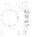
- FIG. 1Apresents top cross-section of a human eye.
- FIG. 1Bpresents a cross-section through the human eye that include the layers of the outer and inner anatomical retina, as indicated by the inset of FIG. 1A .
- FIG. 2Ais a plan view of a preferred embodiment of RSD, showing the general plan structure of RSDs.
- FIG. 2Cis a section view showing the placement of a RSD of FIGS. 2A and 2B in the subretinal space of the eye.
- FIG. 3Ais a plan view of another preferred embodiment of the RSD showing the silicon tail of the RSD that contains the ground return electrode.
- FIG. 3Bis a sectional view of the preferred embodiment of the RSD of this invention at II—II of FIG. 3A .
- the insetis a magnified portion of FIG. 3B .
- FIG. 3Cis a section view showing the placement of the RSD of FIGS. 3A and 3B in the subretinal space of an eye with the silicon tail and ground return electrode in the vitreous cavity.
- FIG. 3Dis a cross-sectional view of the modified embodiment of FIGS. 3A and 3B showing the main photodiode portion of the RSD in the subretinal space and the extended tail of the RSD in the anterior chamber of the eye where it terminates in a photodiode array connected in series and/or parallel with the main photodiode of the RSD to provide additional voltage and/or current to stimulate the retina.
- the ground return electrodeis located on the photodiode array placed in the eye's anterior chamber.
- FIGS. 4A and 4Bare plan and sectional views respectively of yet another preferred embodiment of a RSD showing at least two photodiodes electrically connected in series on the RSD to increase the voltage and resultant current output of the device.
- the sectional view 4 Bis through III—III of the plan view 4 A.
- FIGS. 5A and 5Bare plan and sectional views respectively of yet another preferred embodiment of a RSD showing an Opsistor photodiode electrical configuration in the RSD to allow biphasic stimulating currents to be produced that are modulated by different wavelengths of light.
- the sectional view 5 Bis through IV—IV of the plan view 5 A.
- the present inventiondiscloses both devices and novel methods to electrically stimulate the retina to improve large areas of retinal visual function and to protect the retina from degeneration.
- the retina of the eyecan be divided into sectors as is commonly accepted in the art. Such sectors are described by the use of the terms temporal, nasal, superior, inferior, by clock hour designation, and by the number of degrees away from the macula.
- the temporal sector of the retinais the retina temporal to a perpendicular plane cutting through retina from the 12 o'clock to the 6 o'clock positions and through the macula.
- the superior sectoris the retina superior to a perpendicular plane cutting through the 9 o'clock to 3 o'clock positions and through the macula.
- the visual field sectorscorrespond oppositely to the retinal sectors as is commonly understood in the art.
- the superior-temporal sector of the retinacorresponds to the inferior-nasal portion of the visual field.
- device or other landmarkincludes all surrounding parts, but not the object, device or landmark, i.e., the object, device or landmark, together with the peripheral portion, constitutes the whole.
- Lightrefers not only to the electromagnetic spectrum that humans can readily perceive visually (approximately 400 nm to 750 nm), but also includes ultraviolet light ( ⁇ 400 nm in wavelength) as well as infrared light (>750 nm in wavelength).
- the inventioncan be used to improve visual function in subjects in which the retina is damaged by disease, degeneration, condition, or trauma and/or to slow down or stop the progression of damage by disease, degeneration, condition or trauma.
- diseases, conditions, degeneration or traumathat are particularly amenable to this treatment include age-related macula degeneration, retinitis pigmentosa, Leber's congenital amaurosis, Stargardt's disease, Best's disease, diabetic retinopathy, long-term retinal detachment, and choroidal damage.
- RSDsmay be fabricated to function suitably with diameters that vary from 0.005 to 25 mm, and thicknesses that vary from 0.2 ⁇ m to 1000 ⁇ m, although those skilled in the art will appreciate that dimensions falling outside of the aforementioned values may also be suitable.
- the stimulating electrode or electrodes contacting the epiretinal or the subretinal side of the neuroretinamay be the anode or cathode with the ground return electrode being the opposite polarity of the stimulating electrode. If the electrodes are on the eye surface, the stimulating electrode or electrodes contacting the outside of the eye may also be the anode or the cathode with the ground return electrode being the opposite polarity of the stimulating electrode.
- the silicon chip RSDis a single photodiode 2 mm diameter and 25 ⁇ m thick with its photoactive surface facing incident light and its retinal stimulating electrode disposed on the same surface and electrically connected to the photodiode. On the opposite surface of the RSD is an electrode electrically connected to the photodiode that serves as the ground return electrode for the RSD.
- the RSD silicon chipis preferably implanted surgically into the subretinal space of an eye in a paracentral location relative to the macula (i.e., peripheral to the macula).
- the retinal stimulating electrode on the photoactive surface of the RSD photodiodeis in contact with the inner retina from the subretinal space and is facing incident light, and the electrode is a cathode. Diffuse electric currents developed by the cathode, when the RSD is exposed to light, stimulate the neuroretina above, surrounding, and at a distance from the RSD to improve the damaged retina's inherent visual function. Such visual function improvement has been observed in a clinical study involving multiple patients implanted with such devices, resulting from chronic subretinal electrical stimulation produced by an implanted, high pixel density, artificial silicon retina device.
- the electrical ground of the RSDis brought into the vitreous cavity via an insulated conductor preferably fabricated on a silicon tail that is part of the RSD with an exposed ground return electrode at the end of the conductor on the tail.
- This configurationdirects the electrical current flow more efficiently between the stimulating and ground return electrodes of the RSD into a more through-the-retina, transretinal route and also through a smaller area of the neuroretina compared to the first RSD embodiment without this tail configuration.
- a modification of this preferred embodimentextends the tail into the lens capsule of the eye where it terminates in a photodiode array connected in series and/or parallel with the main RSD to provide additional voltage and/or current to stimulate the neuroretina.
- the purpose of placing the photodiode array in the lens capsuleis to allow the photodiode array to be exposed to brighter intensities of incident light.
- the ground return electrodeis located on the photodiode array placed in the lens capsule.
- At least two photodiodesare fabricated on the RSD that are electrically connected in series to produce higher voltages and higher resultant currents than is possible without such series connections.
- the RSDis fabricated in versions where the ground return electrode is located either in the subretinal space, or in the vitreous cavity at the end of a silicon tail (Chow and Chow, U.S. application Ser. No. 09/539,399).
- fenestrationsare fabricated into any of the aforementioned preferred embodiments of the RSD.
- the fenestrationsallow nourishment and oxygen to flow beneficially from the choroidal circulation and the outer anatomical retina into the inner anatomical retina for RSDs placed in the subretinal space.
- an RSD 10when inserted in the subretinal layer, it is inserted within the retina between the inner retinal layer 56 (that may or may not contain a functional photoreceptor layer 54 ) and the outer retinal layer 62 , in the potential space zone 72 .
- the overlying inner retinal layerconsisting of photoreceptors and their cell bodies 54 , 52 , bipolar cells 48 and horizontal cells 52 are also shown.
- the bipolar cells 48 and ganglion cells 44are in the innermost area of the inner retinal layer, processing visual cues such as electric signals for distant transmission through the optic nerve to the brain.
- the RSDhas a stimulating electrode side 12 and a ground return electrode side 16 .
- the RSDis fabricated on a single thin silicon chip substrate 11 and is implanted into the subretinal space.
- the stimulating electrode side 12includes at least one stimulating electrode 14 a and the ground return electrode side 16 includes at least one ground return electrode 14 b .
- Electric currentis produced by the RSD photodiode photodetector 18 but may be provided by other and external current sources, such as a connected external power supply to the photodiode photodetector. In the presence of such external current sources, the photodiode would also act in a photoconductor mode.
- the stimulating electrode 14 acontacts the neuroretina from the subretinal space.
- the ground return electrode 14 bcontacts the retinal pigment epithelium or the remnant of this structure also from the subretinal space.
- exemplary components of the preferred embodiment of RSD 10include the thin P silicon substrate 11 , an iridium/iridium oxide stimulating electrode 14 a , a titanium adhesion layer 15 a , the N+ layer 16 a , the intrinsic layer 17 , the P+ layer 16 b , the titanium adhesion layer 15 b for the iridium/iridium oxide ground return electrode 14 b .
- the photodiode 18 or other electrical sourcepreferably provides stimulation to the neuroretina from the subretinal side of the eye.
- the electrical source for stimulationcould be provided from outside the eye.
- an electrical voltage/current sourcesuch as a programmed DC or AC power supply-could send voltage and current via hardwiring to an electrode or electrodes in the subretinal space or even into the vitreous cavity of the eye.
- a power sourcecould transmit a signal in a wireless fashion into the eye using, for example, radio frequency (RF) telemetry systems to send signals to a coil located in the eye that communicates with the stimulation and ground electrodes that convert the RF signal into electric current.
- RFradio frequency
- a power source external to the eyee.g. a battery and current management electronics
- the external power sourcemay supply the electrical signal to the RSD electrode in a wired or wireless manner, and the electrical signal can be related or unrelated to incident light. It will be obvious to those skilled in the art that other common mechanisms are also available for providing electrical energy into the eye to beneficially stimulate the retina.
- FIG. 2Cis a cross-sectional view showing a preferred embodiment RSD 10 of FIGS. 2A and 2B implanted in the eye 6 in the subretinal space between the neuroretina 150 and the retinal pigment epithelium 152 .
- Light 156 entering the eye 6 through the cornea 158 and lens 160is focused onto the RSD 10 .
- Electrical currentis generated by the RSD and provides beneficial stimulation to the overlying neuroretina 150 .
- other structures of the eye 6that are shown are the iris 162 , the sclera 164 and the optic nerve 166 .
- another preferred RSD embodiment of this invention 20has a stimulating electrode unit 23 and a curved ground return electrode unit 26 configured for implantation into an eye such that the retinal device 20 may be positioned completely inside the eye and stimulate opposite or substantially opposite sides of the neuroretina.
- the two components 23 and 26are preferably physically fabricated on a single thin silicon chip substrate 22 , but may be fabricated separately and then joined together.
- the stimulating electrode unit 23includes at least one stimulating electrode 23 b powered by one or more electrical sources such as a photodetector 23 a or photodetectors. In this embodiment, the photodetector is implemented as a photodiode 23 a.
- the stimulating electrode 23 bcontacts the neuroretina from the subretinal side.
- the ground return electrode 24is preferably disposed at or near the tip of the ground return electrode unit 26 .
- the stimulating electrode 23 b and the ground return electrode 24are disposed on opposite sides of a neuroretina, or if the neuroretina is partially missing or damaged, then on opposite sides of the remainder of the neuroretina.
- the stimulating electrode 23 bis disposed in the subretinal space of the neuroretina and the ground return electrode 24 is disposed on the epiretinal side of the neuroretina in the vitreous cavity.
- the ground return electrode 24is preferably produced of iridium/iridium oxide and includes a titanium adhesion layer 24 a and a P+ tub 24 b disposed under a titanium adhesion layer 24 a to allow electrical contact with the P doped silicon substrate 22 .
- the retinal device 20also preferably includes a silicon dioxide layer 25 that insulates the stimulating electrode unit 23 and ground return electrode unit 26 .
- the stimulating electrode unit 23includes at least one photodiode 23 a electrically connected to its stimulating electrode 23 b .
- the preferred number of photodiodes 23 ais one per stimulating electrode unit 23 .
- the layers of the photodiode 23 aare, for example, from the incident light surface, the iridium/iridium oxide electrode 23 b , titanium adhesion layer 23 c , N+ tub 23 d , intrinsic layer 23 e , the P doped silicon substrate 22 , and the silicon dioxide insulating layer 25 .
- the stimulating electrode 23 bprovides electric current derived from other sources, such as an external power supply hard wired to electrode 23 b .
- an external power supplyhard wired to electrode 23 b .
- the described preferred embodimentis that of a NIP device, those skilled in the art will be able to readily fabricate a PIN device based on the aforementioned description that is also suitable for retinal stimulation.
- the ground return electrode unit 26preferably includes a positioning hole 25 a that allows the retinal device 20 to be positioned surgically with instruments.
- the ground return electrode unit 26in another embodiment includes notches 26 a that allow a secure fit for attachments that have corresponding protrusions that fit into the notches 26 a , as described in more detail below.
- FIG. 3Cis a cross-sectional view showing the second preferred embodiment RSD 20 of FIGS. 2A and 2B implanted in the eye 6 .
- the stimulating electrode unit 23is located in the subretinal space between the neuroretina 150 and the retinal pigment epithelium 152 while the ground return electrode unit 26 is located in the vitreous cavity 154 .
- Light 156 entering the eye 6 through the cornea 158 and lens 160is focused onto the RSD 20 .
- Electrical currentis generated by the RSD that provides beneficial stimulation to the overlying and surrounding neuroretina 150 .
- other structures of the eye 6that are shown are the iris 162 , the sclera 164 , the optic nerve 166 , lens 160 and cornea 158 .
- FIG. 3Dshows a cross-sectional view of a modification 20 e of a preferred embodiment RSD of FIGS. 2A and 2B that includes a preferred embodiment RSD 20 as described in FIGS. 2A , 2 B and 2 C, and an attached tail extension 27 that electrically connects with at least one bias photodiode 28 preferably disposed in front of the iris 162 of the eye 6 .
- the placement of at least one bias photodiode in this locationallows the bias photodiode or photodiodes to be better exposed to light, compared to bias photodiodes, for example, disposed behind the iris.
- the bias photodiode 28also contains the extended location of the ground return electrode 29 , and the bias photodiode or photodiodes 28 provide additional voltage and/or current to the electrode stimulating unit 23 in the subretinal space.
- the bias photodiode or photodiodes 28are electrically connected together in a series or parallel configuration to provide increased voltage and/or current as needed, and as is known in the art.
- other structures of the eye 6that are shown are the cornea 158 , lens 160 , sclera 164 , neuroretina 150 , retinal pigment epithelium 152 and optic nerve 166 , and the incident light images 156 .
- FIGS. 4A and 4Bare plan and sectional views respectively of another embodiment of a preferred RSD showing multiple photodiodes 32 and 33 electrically connected in series on the RSD 30 to increase the voltage output of the device.
- the sectional view 4 Bis through III—III of the plan view 4 A.
- FIGS. 4A and 4Bshow the stimulating electrode unit 31 includes at least two photodiodes 32 and 33 electrically connected in series to their stimulating electrode 33 b and its ground electrode 34 .
- the ground electrode unit 36contains a positioning hole 34 a .
- the preferred number of photodiodes per RSD 30is two; however, based on the design of this RSD embodiment, one ordinarily skilled in the art can readily produce a device with additional photodiodes connected electrically in series to the stimulation electrode 33 b and ground return electrode 34 .
- the layers of the photodiodes 32 and 33are, for example, from the incident light surface, an iridium/iridium oxide stimulating electrode 33 b , iridium/iridium oxide connecting straps 34 c over titanium adhesion layers 33 c , N+ tubs 33 d , intrinsic layers 33 e , the P+ layers 33 f , channel stop region 35 a , P silicon substrate 31 e , and silicon dioxide insulating layers 35 .
- the stimulating electrode 33 bprovides electric current derived from other sources such as a receiving inductive coil implanted in the vitreous cavity and powered by an external transmitting inductive coil, or such as an external power supply hard wired to electrode 33 b .
- a receiving inductive coilimplanted in the vitreous cavity and powered by an external transmitting inductive coil, or such as an external power supply hard wired to electrode 33 b .
- an external power supplyhard wired to electrode 33 b .
- the described preferred embodimentis that of a NIP device, a PIN device based on the aforementioned description that is also suitable for retinal stimulation.
- FIGS. 5A and 5Bshow that the stimulating electrode unit 41 includes at least two photodiodes 42 and 43 electrically connected in a reverse parallel Opsistor fashion terminating in a stimulating electrode 47 and a ground return electrode 44 .
- the ground return electrode unit 46contains a positioning hole 44 a .
- the number of photodiodes per RSD 40is two. However, more than two photodiodes per RSD are also contemplated. More detail on versions of these RSDs has been described (Chow and Chow, U.S. Pat. No. 5,837,995, 1998; Chow and Chow, U.S. application Ser. No. 09/564,841; Chow and Chow, U.S. application Ser. No.
- the photodiodes 42 and 43receive power from incident light, and each photodiode is powered predominantly by a different wavelength of light as determined by the light filters 45 a and 45 b .
- one light filter 45 a or 45 bpasses a portion of visible and/or infrared light while the other filter passes another portion of visible and/or infrared light.
- the structures shownare the iridium/iridium oxide stimulation electrode 47 , iridium/iridium oxide ground return electrode 44 , titanium adhesion layers and titanium connecting straps 44 c , N+ tubs 43 d , intrinsic layers 43 e , P+ layers 43 f , channel stop region 45 a , P silicon substrate 41 e , and silicon dioxide insulating layers 45 .
- Other arrangementsmay be used where the stimulating electrode 47 and ground return electrode 44 provide electric current derived from another source, such as an external power supply hard wired to the electrodes 47 and 44 , or such as a receiving inductive coil implanted in the vitreous cavity and powered by an external transmitting inductive coil.
- FIG. 6is a perspective view of another embodiment 50 of the RSDs shown in FIGS. 2A and 2B , and 3 A and 3 B.
- the stimulation electrode unit 52 a of this preferred embodiment 50is similar to the stimulation electrode units of the preferred embodiments of FIGS. 2A and 2B , and FIGS. 3A and 3B except that the stimulation electrode unit 52 a is perforated. It is fabricated as a disk-shaped silicon web to allow nourishment to flow between the choroid and the neuroretina, and it has at least one perforated electrode 53 b encompassing the surface of the stimulation electrode unit 52 a .
- the ground return electrode unit 56is fabricated with at least one positioning hole 54 a and at least one ground return electrode is 54 .
- FIG. 7is a cross-sectional view showing another preferred RSD embodiment 60 implanted in an eye 6 on the epiretinal surface between the vitreous 154 and the neuroretina 150 .
- This RSD embodiment 60is similar to the RSD 10 of FIGS. 2A and 2B .
- the RSDis secured on the epiretinal surface by retinal tacks 62 or a biocompatible glue as is well known to those skilled in the art.
- Light 156 entering the eye 6 through the cornea 158 and lens 160is focused onto the RSD 60 . Electric current is generated by the RSD 60 to provide beneficial stimulation to the underlying neuroretina 150 .
- the stimulation electrode that contacts the neuroretinais a cathode and the ground return electrode of the RSD 60 contacts the vitreous fluid 154 is the anode.
- the reversed position of the anode and the cathodeis also suitable for electrical stimulation.
- other structures of the eye 6 that are shownare the iris 162 , the sclera 164 and the optic nerve 166 .
- FIG. 8is a cross-sectional view showing another preferred RSD embodiment 70 implanted in an eye 6 on the anterior scleral surface between the conjunctiva 159 and the sclera 164 preferably nasal or temporal to the cornea.
- This RSD embodiment 70is similar to the RSD 10 of FIGS. 2A and 2B .
- the RSDis secured in the subconjunctival space by the conjunctiva 159 on the RSD 70 anterior surface and the sclera 164 on the RSD 70 posterior surface.
- Light 156 passing through the conjunctiva 159illuminates the RSD 70 .
- Electric potentialis generated by the RSD 70 that provides beneficial stimulation to the neuroretina 150 via conduction through the sclera 164 .
- the stimulation electrode that contacts the sclera 164is a cathode and the ground return electrode of the RSD 70 that contacts the conjunctiva 159 is the anode.
- the reversed position of the anode and the cathodeis also suitable for electrical stimulation.
- other structures of the eye 6that are shown are the iris 162 , the sclera 164 and the optic nerve 166 .
- the devices in Table Aare also preferred.
- Multi-phasic Photodiode RetinalChow and Chow, U.S. Pat. No. Implants (MMRIs, such as MMRI-4) 5,895,415, 1999; Chow and Chow, U.S. Pat. No. 6,230,057 B1, 2001)
- VGMMRIsVariable Gain Multi-phasic
- the electrical stimulationif provided by implants such as the RSDs described above, may be provided subretinally, epiretinally, subsclerally (between the sclera and choroid), on the scleral surface, on the conjuctival surface and/or from or within any structure of the eye.
- Other means of providing electrical simulation to the retina and eyemay include devices that deliver stimulation from the underside of the eyelid(s).
- stimulationis from the subretinal space. Electrical stimulation from the exterior of the eyelid is not preferred.
- the RSD or RSDsis preferably implanted in the subretinal space in the periphery and/or mid-periphery of the eye, outside of the macula. More than one RSD is implanted, if needed, in an eye to stimulate a larger area of the retina, and multiple RSDs would preferably be implanted in paracentral locations such as one in each of the four paracentral quadrants, approximately, but not limited to, 5 to 80 degrees peripheral to the macula.
- FIG. 9is a cross-sectional view of an eye 6 showing an array 200 of RSDs 10 in the subretinal space.
- the RSDsmay be spaced symmetrically around the macula in the peripheral or mid-peripheral regions of the eye in one embodiment. Alternatively, the RSDs may be spaced asymmetrically around the macula.
- the RSDsare implanted at a position in the subretinal space between about a 5 degrees and an 80 degrees angle off-axis from the macula, where the angle is defined by an intersection of an axis line extending from the macula to a central portion of the pupil and an off-axis line extending from the retina stimulation device to the central portion of the pupil.
- the RSDsmay also be implanted in the temporal half retina region and/or nasal half retina region, within the subretinal space. Any of a number of techniques and instruments may be used to perform the implantation into the subretinal space (Chow, U.S. Pat. No. 5,024,223, 1991; Chow and Chow, U.S. Pat. No. 5,397,350, 1995).
- the RSDis designed to be implanted onto the epiretinal surface (i.e. on the nerve fiber layer side) of the retina. It is retained in position by retinal tacks, biocompatible glues, or other means known to one skilled in the art.
- the photoactive side of the RSDi.e. the side directed towards incoming light, is the anode of the photodiode.
- the cathodeOn the opposite side of the RSD chip is the cathode, contacting the nerve fiber layer surface.
- This preferred embodiment RSDis also implantable in the subconjunctival space on the anterior scleral surface.
- the RSDis placed between the conjunctiva and the sclera just nasal, temporal, superior, or inferior to the cornea. From this location, incident light causes electric current to be produced by the RSD that is directed through the sclera into the retina by the contacting scleral cathode.
- the preferred locationsare nasal and temporal to the cornea.
- the electrical ground returnis at the anode and is in contact with the underside of the conjunctiva.
- the subconjunctival/scleral placement of the RSDresults in less efficient electrical stimulation of the retina compared to a subretinally or epiretinally placed RSD, the extraocular location of a RSD decreases the surgical risk to a patient since intraocular surgery would not be required for its implantation.
- the subconjunctival/scleral placement of a RSDalso allows a stable RSD position to be achieved without fixating devices or glues (i.e., the device is held in place between the conjunctiva and sclera) used to secure epiretinal RSDs.
- the deviceis then placed into the subretinal cavity at the posterior pole under the macula area. Specifically, the device is placed between the retinal pigment epithelium and photoreceptor layer, or if the photoreceptor layer is atrophied or lost, then between the retinal pigment epithelium and the bipolar and horizontal cell layer. The device is positioned such that the electrical ground(s) is overlaying the retinal pigment epithelium, and the active electrode(s) faces incident light.
- endolaserphotocoagulation or endocautery burnsmay be made around the periphery of the device to secure the device, although these burns may not be necessary in many cases.
- the scar tissue so formed around the periphery of the device by these burnsmay prevent the device from moving out of position in some patients.
- Endolaserphotoco-agulation or endoelectrocauterymay also be used to seal the retinal incision.
- Air or other medically approved gaseous compoundsmay also be injected into the vitreous cavity to tamponade the retinal opening during healing. The pars plana incision is then closed in the usual surgical manner.
- An alternate method for implantation of the RSDinvolves making an incision through the sclera just posterior to the ora serata. Dissection proceeds through the choroid, choriocapillaris, Bruch's membrane and retinal pigment epithelium under stereo operating microscope control into the potential space between the inner and outer anatomical retinal layers. The artificial retinal implant is then inserted into this space and directed posteriorly towards the macula by a pushing action imparted by a formed curved iris spatula or by use of an insertion guide. The RSD rests in the retinal periphery of the eye between the inner and outer anatomical retinal layers.
- some devicescan be implanted by simple injection into the subretinal space through cannulas.
- the RSDsare placed in a vehicle such as a biocompatible liquid and injected into the subretinal space via a retinotomy incision using a cannula.
- a liquid vehiclemay be a balanced salt solution or a more viscous material like methylcellulose.
- the retinais preferably illuminated by a light pipe to facilitate the injection of the RSDs.
- the cannulais introduced into the vitreous cavity of the eye via a pars plana incision. Dissection of the posterior vitreous is performed to separate the posterior hyaloid face from the retinal surface along with a vitrectomy. A small retinotomy incision is made through the retina following the direction of the nerve fiber layer using a stiletto type MVR blade. Dissection of the inner retina from the outer retinal layers is accomplished hydrostatically with the cannula using a fluid such as saline.
- the liquid vehicle with suspended RSDsis injected.
- the cannulais then withdrawn, and a heavier-than-water non-miscible material (preferably, a perfluorocarbon) is placed over the posterior pole of the vitreous cavity to aid settling the retina.
- the non-miscible materialis preferably removed after an appropriate time, usually 15 to 20 minutes, leaving a reattached retina.
- airmay also be used to settle the retina. With settling and reattachment of the retina, the implanted RSDs tend to distribute into the desired monolayer.
- growth factorsinclude, but are not limited to, glial cell line-derived neurotrophic factor (GDNF), nerve growth factor (NGF), brain derived neurotrophic growth factor (BDNGF), neurotropin ⁇ 3 (NT ⁇ 3), neurotropin ⁇ 4 (NT ⁇ 4), neurotropin ⁇ 5 (NT ⁇ 5), ciliary neurotropic factor (CNTF) and fibroblastic growth factor (FGF).
- GDNFglial cell line-derived neurotrophic factor
- NNFnerve growth factor
- BDNGFbrain derived neurotrophic growth factor
- NT ⁇ 3neurotropin ⁇ 3
- NT ⁇ 4neurotropin ⁇ 4
- NT ⁇ 5neurotropin ⁇ 5
- CNTFciliary neurotropic factor
- FGFfibroblastic growth factor
- growth factorscan be delivered to the eye by coating the RSD with growth factor(s) before implantation, by injection of the growth factor(s) into the locations of the subretinal space, vitreous cavity, subconjunctival space, subscleral space, and/or the anterior chamber either singly or in combination with each other, as a single dose or as multiple repeat doses before, during and/or after implantation of the RSD(s) or other electrical stimulating device.
- electrical stimulationis generated upon exposure to visible and/or infrared light (400 to greater than 750 nm); in the case of MMRIs, the NIP configuration provides a current when illuminated with visible light (400–750 nm), while the PIN configuration provides a current when illuminated with infrared light (greater than 750 nm).
- the RSDsmay be designed to respond to any wavelength or wavelength portions of ultraviolet, visible and/or infrared light, using methods and designs such as those described (Chow and Chow, U.S. Pat. No. 6,230,057 B1, 2001) and to produce any temporal pattern of stimulation.
- the produced current per RSDmay be 0.01 nA to 2,000,000 nA; most preferably 1 to 5000 nA and the temporal pattern of stimulation may be monophasic, biphasic or complex combinations of monophasic and biphasic waveforms with varying ramps of increasing and decreasing current and voltage. Electrical stimulation may also be provided continuously or intermittently.
- the electric current output of the RSDwill depend on the degree of RSD stimulation by the appropriate light wavelengths or wavelength portions of light.
- the voltage potential of the RSD outputis ⁇ 20V to +20V, preferably ⁇ 5V to +5V, and most preferably ⁇ 1V to +1V.
Landscapes
- Health & Medical Sciences (AREA)
- Public Health (AREA)
- Ophthalmology & Optometry (AREA)
- Engineering & Computer Science (AREA)
- Biomedical Technology (AREA)
- Veterinary Medicine (AREA)
- Life Sciences & Earth Sciences (AREA)
- Animal Behavior & Ethology (AREA)
- General Health & Medical Sciences (AREA)
- Heart & Thoracic Surgery (AREA)
- Vascular Medicine (AREA)
- Nuclear Medicine, Radiotherapy & Molecular Imaging (AREA)
- Radiology & Medical Imaging (AREA)
- Prostheses (AREA)
- Medicines Containing Material From Animals Or Micro-Organisms (AREA)
- Materials For Medical Uses (AREA)
Abstract
Description
| TABLE A | |
| Device | References |
| Artificial Silicon Retina (ASR ™) | (Chow, U.S. Pat. No. 5,016,633, |
| 1991; Chow, U.S. Pat. No. | |
| 5,024,223, 1991) | |
| Independent Surface Electrode | (Chow and Chow, U.S. Pat. No. |
| Microphotodiodes (ISEMCP) | 5,397,350, 1995; Chow and Chow, |
| U.S. Pat. No. 5,556,423, 1996) | |
| Independent Surface Electrode | (Chow and Chow, U.S. Pat. No. |
| Microphotodiodes with an electrical | 5,397,350, 1995; Chow and Chow, |
| capacitor (ISEMCP-Cs) | U.S. Pat. No. 5,556,423, 1996) |
| Multi-phasic Photodiode Retinal | (Chow and Chow, U.S. Pat. No. |
| Implants (MMRIs, such as MMRI-4) | 5,895,415, 1999; Chow and Chow, |
| U.S. Pat. No. 6,230,057 B1, 2001) | |
| Variable Gain Multi-phasic | (Chow and Chow, US Application |
| Photodiode Retinal Implants | No. 09/539,399, 2000) |
| (VGMMRIs) | |
Claims (8)
Priority Applications (14)
| Application Number | Priority Date | Filing Date | Title |
|---|---|---|---|
| US10/056,793US7031776B2 (en) | 2001-06-29 | 2002-01-23 | Methods for improving damaged retinal cell function |
| AU2002352103AAU2002352103B2 (en) | 2001-06-29 | 2002-06-27 | Methods for improving damaged retinal cell function |
| PCT/US2002/020557WO2003002190A2 (en) | 2001-06-29 | 2002-06-27 | Methods for improving damaged retinal cell function |
| EP02780956AEP1409073A4 (en) | 2001-06-29 | 2002-06-27 | Methods for improving damaged retinal cell function |
| BR0210699-0ABR0210699A (en) | 2001-06-29 | 2002-06-27 | Methods for Improving Function of Damaged Retinal Cells |
| EP02740010AEP1409072A4 (en) | 2001-06-29 | 2002-06-28 | Methods for improving damaged retinal cell function using physical and/or mechanical stimulation |
| US10/186,295US20030028225A1 (en) | 2001-06-29 | 2002-06-28 | Methods for improving damaged retinal cell function using physical and/or mechanical stimulation |
| BR0210748-1ABR0210748A (en) | 2001-06-29 | 2002-06-28 | Processes for Enhancing Damaged Retinal Cell Function Using Physical and / or Mechanical Stimulation |
| PCT/US2002/020808WO2003002070A2 (en) | 2001-06-29 | 2002-06-28 | Methods for improving damaged retinal cell function using physical and/or mechanical stimulation |
| US10/606,117US20040106965A1 (en) | 2001-06-29 | 2003-06-24 | Methods and apparatus for treatment of degenerative retinal disease via indirect electrical stimulation |
| US10/822,437US20050033202A1 (en) | 2001-06-29 | 2004-04-12 | Mechanically activated objects for treatment of degenerative retinal disease |
| US10/863,519US20050004625A1 (en) | 2001-06-29 | 2004-06-09 | Treatment of degenerative retinal disease via electrical stimulation of surface structures |
| US11/301,352US20060142818A1 (en) | 2001-06-29 | 2005-12-12 | Methods for improving damaged retinal cell function |
| US12/576,891US7981062B2 (en) | 2001-06-29 | 2009-10-09 | Mechanically activated objects for treatment of degenerative retinal disease |
Applications Claiming Priority (2)
| Application Number | Priority Date | Filing Date | Title |
|---|---|---|---|
| US30187701P | 2001-06-29 | 2001-06-29 | |
| US10/056,793US7031776B2 (en) | 2001-06-29 | 2002-01-23 | Methods for improving damaged retinal cell function |
Related Child Applications (3)
| Application Number | Title | Priority Date | Filing Date |
|---|---|---|---|
| US10/186,295Continuation-In-PartUS20030028225A1 (en) | 2001-06-29 | 2002-06-28 | Methods for improving damaged retinal cell function using physical and/or mechanical stimulation |
| US10/606,117Continuation-In-PartUS20040106965A1 (en) | 2001-06-29 | 2003-06-24 | Methods and apparatus for treatment of degenerative retinal disease via indirect electrical stimulation |
| US11/301,352ContinuationUS20060142818A1 (en) | 2001-06-29 | 2005-12-12 | Methods for improving damaged retinal cell function |
Publications (2)
| Publication Number | Publication Date |
|---|---|
| US20030014089A1 US20030014089A1 (en) | 2003-01-16 |
| US7031776B2true US7031776B2 (en) | 2006-04-18 |
Family
ID=26735714
Family Applications (3)
| Application Number | Title | Priority Date | Filing Date |
|---|---|---|---|
| US10/056,793Expired - LifetimeUS7031776B2 (en) | 2001-06-29 | 2002-01-23 | Methods for improving damaged retinal cell function |
| US10/186,295AbandonedUS20030028225A1 (en) | 2001-06-29 | 2002-06-28 | Methods for improving damaged retinal cell function using physical and/or mechanical stimulation |
| US11/301,352AbandonedUS20060142818A1 (en) | 2001-06-29 | 2005-12-12 | Methods for improving damaged retinal cell function |
Family Applications After (2)
| Application Number | Title | Priority Date | Filing Date |
|---|---|---|---|
| US10/186,295AbandonedUS20030028225A1 (en) | 2001-06-29 | 2002-06-28 | Methods for improving damaged retinal cell function using physical and/or mechanical stimulation |
| US11/301,352AbandonedUS20060142818A1 (en) | 2001-06-29 | 2005-12-12 | Methods for improving damaged retinal cell function |
Country Status (5)
| Country | Link |
|---|---|
| US (3) | US7031776B2 (en) |
| EP (2) | EP1409073A4 (en) |
| AU (1) | AU2002352103B2 (en) |
| BR (2) | BR0210699A (en) |
| WO (2) | WO2003002190A2 (en) |
Cited By (24)
| Publication number | Priority date | Publication date | Assignee | Title |
|---|---|---|---|---|
| US20060142818A1 (en)* | 2001-06-29 | 2006-06-29 | Optobionics | Methods for improving damaged retinal cell function |
| US20060184062A1 (en)* | 2005-02-16 | 2006-08-17 | Greenberg Robert J | Fitting of brightness in a visual prosthesis |
| US20070093877A1 (en)* | 2005-10-26 | 2007-04-26 | Beecham Michael C | System for maintaining normal health of retinal cells and promoting regeneration of retinal cells |
| US20100121231A1 (en)* | 2001-06-29 | 2010-05-13 | Chow Alan Y | Mechanically activated objects for treatment of degenerative retinal disease |
| US20100204754A1 (en)* | 2009-02-09 | 2010-08-12 | Rainbow Medical Ltd. | Retinal prosthesis |
| US20100241060A1 (en)* | 2009-03-18 | 2010-09-23 | Roizman Keith | Surgical devices and methods |
| US20100249877A1 (en)* | 2007-11-21 | 2010-09-30 | The Trustees Of Boston College | Apparatus and Methods for Visual Perception Using an Array of Nanoscale Waveguides |
| US20110172736A1 (en)* | 2010-01-14 | 2011-07-14 | Nano-Retina, Inc. | Penetrating electrodes for retinal stimulation |
| US20120192416A1 (en)* | 2005-04-28 | 2012-08-02 | Jordan Matthew Neysmith | Flexible Circuit Electrode Array |
| US8428740B2 (en) | 2010-08-06 | 2013-04-23 | Nano-Retina, Inc. | Retinal prosthesis techniques |
| US8442641B2 (en) | 2010-08-06 | 2013-05-14 | Nano-Retina, Inc. | Retinal prosthesis techniques |
| US8571669B2 (en) | 2011-02-24 | 2013-10-29 | Nano-Retina, Inc. | Retinal prosthesis with efficient processing circuits |
| US8706243B2 (en) | 2009-02-09 | 2014-04-22 | Rainbow Medical Ltd. | Retinal prosthesis techniques |
| US9037251B2 (en) | 2010-06-28 | 2015-05-19 | Jawaharlal Nehru Centre For Advanced Scientific Research | Artificial retina device |
| US9322713B2 (en) | 2011-08-30 | 2016-04-26 | Jawaharlal Nehru Centre For Advanced Scientific Research | Artificial retina device |
| US9331791B2 (en) | 2014-01-21 | 2016-05-03 | Nano Retina Ltd. | Transfer of power and data |
| US9370417B2 (en) | 2013-03-14 | 2016-06-21 | Nano-Retina, Inc. | Foveated retinal prosthesis |
| US9474902B2 (en) | 2013-12-31 | 2016-10-25 | Nano Retina Ltd. | Wearable apparatus for delivery of power to a retinal prosthesis |
| US20200251507A1 (en)* | 2015-09-15 | 2020-08-06 | Pixium Vision Sa | Photosensitive pixel structure with front side coating |
| US11305118B2 (en) | 2018-11-30 | 2022-04-19 | Biovisics Medical, Inc. | Head worn apparatuses for vision therapy |
| US11338139B2 (en) | 2018-10-01 | 2022-05-24 | Biovisics Medical, Inc. | System and methods for controlled electrical modulation for vision therapy |
| US11471680B2 (en) | 2019-04-10 | 2022-10-18 | Biovisics, Inc. | Systems and interfaces for ocular therapy |
| US11511112B2 (en) | 2019-06-14 | 2022-11-29 | Biovisics Medical, Inc. | Wearable medical device |
| US12023498B2 (en) | 2019-07-12 | 2024-07-02 | Biovisics Medical, Inc. | Ocular therapy modes and systems |
Families Citing this family (62)
| Publication number | Priority date | Publication date | Assignee | Title |
|---|---|---|---|---|
| US6699285B2 (en)* | 1999-09-24 | 2004-03-02 | Scieran Technologies, Inc. | Eye endoplant for the reattachment of a retina |
| US20050004625A1 (en) | 2001-06-29 | 2005-01-06 | Chow Alan Y. | Treatment of degenerative retinal disease via electrical stimulation of surface structures |
| US7147865B2 (en) | 2001-06-29 | 2006-12-12 | The Board Of Trustees Of The Leland Stanford University | Artificial synapse chip |
| WO2003061537A1 (en)* | 2002-01-17 | 2003-07-31 | Masachusetts Eye And Ear Infirmary | Minimally invasive retinal prosthesis |
| US7367671B2 (en) | 2002-02-08 | 2008-05-06 | Novavision, Inc. | Process and device for the training of human vision |
| US20040233383A1 (en)* | 2002-12-16 | 2004-11-25 | Sandler Richard H. | Artificial iris and lens apparatus |
| US7483750B2 (en)* | 2003-03-21 | 2009-01-27 | Second Sight Medical Products, Inc. | Transretinal implant and method of implantation |
| US8014878B2 (en) | 2005-04-28 | 2011-09-06 | Second Sight Medical Products, Inc. | Flexible circuit electrode array |
| US7321795B2 (en)* | 2003-03-24 | 2008-01-22 | Les Bogdanowicz | Compositions for electric stimulation of the eye |
| WO2004096146A2 (en)* | 2003-04-25 | 2004-11-11 | Nolan Gerard M | Method and composition for preventing, reducing and reversing ocular ischemic neuronal damage |
| US7127301B1 (en) | 2003-04-28 | 2006-10-24 | Sandia Corporation | Flexible retinal electrode array |
| US8260428B2 (en)* | 2003-05-01 | 2012-09-04 | California Institute Of Technology | Method and system for training a visual prosthesis |
| US7321796B2 (en)* | 2003-05-01 | 2008-01-22 | California Institute Of Technology | Method and system for training a visual prosthesis |
| WO2006002070A2 (en) | 2004-06-15 | 2006-01-05 | Novavision, Inc. | Method and device for guiding a user's head during vision training |
| US20060224212A1 (en)* | 2005-04-01 | 2006-10-05 | Kennedy Philip R | Neural electrode array |
| US8078275B2 (en)* | 2005-04-15 | 2011-12-13 | Functional Neuromodulation Inc. | Regulation of neurotrophins |
| US10022457B2 (en) | 2005-08-05 | 2018-07-17 | Gholam A. Peyman | Methods to regulate polarization and enhance function of cells |
| US9962558B2 (en) | 2005-08-05 | 2018-05-08 | Gholam A. Peyman | Methods to regulate polarization and enhance function of cells |
| US8460351B2 (en) | 2005-08-05 | 2013-06-11 | Gholam A. Peyman | Methods to regulate polarization and enhance function of excitable cells |
| US8562660B2 (en) | 2005-08-05 | 2013-10-22 | Gholam A. Peyman | Methods to regulate polarization and enhance function of excitable cells |
| US8409263B2 (en)* | 2005-08-05 | 2013-04-02 | Gholam A. Peyman | Methods to regulate polarization of excitable cells |
| US8956396B1 (en)* | 2005-10-24 | 2015-02-17 | Lockheed Martin Corporation | Eye-tracking visual prosthetic and method |
| US8945197B1 (en)* | 2005-10-24 | 2015-02-03 | Lockheed Martin Corporation | Sight-restoring visual prosthetic and method using infrared nerve-stimulation light |
| EP1968427A2 (en) | 2005-12-16 | 2008-09-17 | Novavision, Inc. | Adjustable device for vision testing and therapy |
| US7610098B2 (en) | 2005-12-20 | 2009-10-27 | Imi Intelligent Medical Implants Ag | Charge-integrating retinal prosthesis and method |
| WO2007084582A2 (en) | 2006-01-17 | 2007-07-26 | Forsight Labs, Llc | Drug delivery treatment device |
| JP2009533157A (en) | 2006-04-12 | 2009-09-17 | プロテウス バイオメディカル インコーポレイテッド | Embedded sealed structure without voids |
| US8583242B2 (en)* | 2008-01-04 | 2013-11-12 | Doheny Eye Institute | Subchoroidal retinal prosthesis |
| EP2291156A4 (en)* | 2008-05-30 | 2014-02-12 | Univ Colorado Regents | NON-INVASIVE DEVICE FOR LOWERING INTRAOCULAR PRESSURE |
| KR101032269B1 (en)* | 2009-02-23 | 2011-05-06 | 한국과학기술연구원 | Biometric wireless electrical stimulation device |
| US8529492B2 (en)* | 2009-12-23 | 2013-09-10 | Trascend Medical, Inc. | Drug delivery devices and methods |
| JP5545962B2 (en)* | 2010-02-16 | 2014-07-09 | 株式会社ニデック | Visual reproduction assist device |
| EP2552539B2 (en)* | 2010-04-01 | 2019-03-06 | Pixium Vision SA | Retinal implant and visual prosthesis incorporating such an implant |
| US9821159B2 (en) | 2010-11-16 | 2017-11-21 | The Board Of Trustees Of The Leland Stanford Junior University | Stimulation devices and methods |
| JP2013542838A (en) | 2010-11-16 | 2013-11-28 | ザ ボード オブ トラスティーズ オブ ザ レランド スタンフォード ジュニア ユニバーシティー | System and method for treating dry eye |
| US9308126B2 (en) | 2010-11-29 | 2016-04-12 | The Regents Of The University Of Colorado, A Body Corporate | Non-invasive devices and methods for lowering intra-ocular pressure |
| US9427569B2 (en)* | 2012-05-09 | 2016-08-30 | Po-Kang Lin | Structure of artificial electronic retina |
| WO2014165124A1 (en) | 2013-03-12 | 2014-10-09 | Oculeve, Inc. | Implant delivery devices, systems, and methods |
| NZ704579A (en) | 2013-04-19 | 2018-10-26 | Oculeve Inc | Nasal stimulation devices and methods |
| ES2812752T3 (en) | 2014-02-25 | 2021-03-18 | Oculeve Inc | Polymer formulations for nasolacrimal stimulation |
| AU2015292278B2 (en) | 2014-07-25 | 2020-04-09 | Oculeve, Inc. | Stimulation patterns for treating dry eye |
| EP3209372B1 (en) | 2014-10-22 | 2020-07-15 | Oculeve, Inc. | Stimulation devices for treating dry eye |
| WO2016065211A1 (en)* | 2014-10-22 | 2016-04-28 | Oculeve, Inc. | Contact lens for increasing tear production |
| US10426958B2 (en) | 2015-12-04 | 2019-10-01 | Oculeve, Inc. | Intranasal stimulation for enhanced release of ocular mucins and other tear proteins |
| US11433260B2 (en) | 2015-12-21 | 2022-09-06 | Gholam A. Peyman | Cancer treatment methods using thermotherapy and/or enhanced immunotherapy |
| US9849092B2 (en) | 2015-12-21 | 2017-12-26 | Gholam A. Peyman | Early cancer detection and enhanced immunotherapy |
| US10300121B2 (en) | 2015-12-21 | 2019-05-28 | Gholam A. Peyman | Early cancer detection and enhanced immunotherapy |
| US11660229B2 (en) | 2015-12-21 | 2023-05-30 | Gholam A. Peyman | Cancer treatment methods using thermotherapy and/or enhanced immunotherapy |
| US10136820B2 (en) | 2015-12-21 | 2018-11-27 | Gholam A. Peyman | Method to visualize very early stage neoplasm or other lesions |
| US11090385B2 (en) | 2015-12-21 | 2021-08-17 | Gholam A. Peyman | Early cancer detection and enhanced immunotherapy |
| US10252048B2 (en) | 2016-02-19 | 2019-04-09 | Oculeve, Inc. | Nasal stimulation for rhinitis, nasal congestion, and ocular allergies |
| US11419543B1 (en) | 2016-03-03 | 2022-08-23 | Gholam A. Peyman | Early disease detection and therapy |
| US10376600B2 (en) | 2016-03-03 | 2019-08-13 | Gholam A. Peyman | Early disease detection and therapy |
| AU2017260237A1 (en) | 2016-05-02 | 2018-11-22 | Oculeve, Inc. | Intranasal stimulation for treatment of meibomian gland disease and blepharitis |
| KR101838150B1 (en)* | 2016-08-31 | 2018-03-15 | 가천대학교 산학협력단 | Photodiode array based sub-retinal prosthetic device and method thereby |
| US10226625B2 (en) | 2016-11-03 | 2019-03-12 | Nano Retina Ltd. | Surgical techniques for implantation of a retinal implant |
| US10272244B2 (en)* | 2016-11-03 | 2019-04-30 | Nano Retina Ltd. | Retinal implant fixation |
| WO2018102535A1 (en) | 2016-12-02 | 2018-06-07 | Oculeve, Inc. | Apparatus and method for dry eye forecast and treatment recommendation |
| US10583283B2 (en) | 2018-01-31 | 2020-03-10 | Nano-Retina, Inc. | Retinal implant with image registration |
| ES3034161T3 (en)* | 2019-03-06 | 2025-08-13 | Centre For Eye Res Australia Ltd | Electrical apparatus for an eye |
| EP4099968A4 (en) | 2020-03-23 | 2024-03-06 | Tectus Corporation | ELECTRONIC INTRAOCULAR DEVICES |
| US11998765B2 (en) | 2020-09-29 | 2024-06-04 | Cancer Rx, LLC | Cancer imaging methods and cancer treatment methods using thermotherapy and drug delivery |
Citations (56)
| Publication number | Priority date | Publication date | Assignee | Title |
|---|---|---|---|---|
| US2760483A (en) | 1953-10-29 | 1956-08-28 | Tassicker Graham Edward | Retinal stimulator |
| US3594823A (en) | 1969-02-11 | 1971-07-27 | Patent Management Inc | Visual substitution system with receptor scanning means |
| US3628193A (en) | 1969-02-19 | 1971-12-21 | Inst Of Medical Sciences The | Tactile image projection system |
| US3766311A (en) | 1972-04-26 | 1973-10-16 | H Boll | Sensory substitution system |
| US3848608A (en) | 1973-07-23 | 1974-11-19 | Gen Electric | Subject integument spatial stimulator |
| US3914800A (en) | 1974-06-06 | 1975-10-28 | Inst Of Medical Sciences | Fluid mechanical tactile oscilloscope to augment the five senses |
| US4001867A (en) | 1974-08-22 | 1977-01-04 | Dionics, Inc. | Semiconductive devices with integrated circuit switches |
| US4211474A (en) | 1977-01-31 | 1980-07-08 | Compagnie Generale D'electricite | Ultra-rapid electro-optical shutter |
| US4251887A (en) | 1979-04-02 | 1981-02-24 | Anis Aziz Y | Posterior chamber capsular lens implant and method for implantation of the lens |
| US4272910A (en) | 1979-07-31 | 1981-06-16 | Danz W R | Ocular prosthetic or the like |
| EP0084621A2 (en) | 1982-01-22 | 1983-08-03 | International Business Machines Corporation | Semiconductor signal conversion device using photon coupling |
| US4551149A (en) | 1982-02-16 | 1985-11-05 | Michael Sciarra | Prosthetic vision system |
| US4600004A (en) | 1982-09-08 | 1986-07-15 | Osvaldo Lopez | Intraocular lens holder and inserter |
| US4601545A (en) | 1984-05-16 | 1986-07-22 | Kern Seymour P | Variable power lens system |
| US4628933A (en) | 1985-07-23 | 1986-12-16 | Michelson Robin P | Method and apparatus for visual prosthesis |
| US4679572A (en) | 1986-03-11 | 1987-07-14 | Intermedics, Inc. | Low threshold cardiac pacing electrodes |
| EP0233789A2 (en) | 1986-02-21 | 1987-08-26 | THE COOPER COMPANIES, INC. (formerly called CooperVision, Inc.) | Tool for inserting an intraocular lens |
| US4810050A (en) | 1985-05-24 | 1989-03-07 | British Telecommunications Public Limited Company | Optical inverter and logic devices using same with buffer limited electrical interface |
| US4832202A (en) | 1986-05-22 | 1989-05-23 | General Foods Limited | Containers |
| US4873448A (en) | 1986-04-30 | 1989-10-10 | Omron Tateisi Electronics Co. | Input circuit having a photo-coupler with bi-directional indicator |
| GB2229543A (en) | 1988-12-26 | 1990-09-26 | Mitsubishi Mining & Cement Co | Photo-driven optical switch |
| US4978842A (en) | 1989-04-21 | 1990-12-18 | At&T Bell Laboratories | Programmable optical logic device with complementary inputs |
| US5016633A (en) | 1989-08-08 | 1991-05-21 | Chow Alan Y | Artificial retina device |
| US5024223A (en) | 1989-08-08 | 1991-06-18 | Chow Alan Y | Artificial retina device |
| US5109844A (en) | 1990-10-11 | 1992-05-05 | Duke University | Retinal microstimulation |
| US5130528A (en) | 1991-03-01 | 1992-07-14 | International Business Machines Corporation | Opto-photo-electric switch |
| US5130776A (en) | 1989-03-16 | 1992-07-14 | Landis & Gyr Betriebs Ag | Ultraviolet-light photodiode |
| US5159927A (en) | 1989-07-26 | 1992-11-03 | Ferdinand Schmid | Visual prosthesis apparatus and method |
| US5223728A (en) | 1992-04-02 | 1993-06-29 | Motorola, Inc. | Optical switch integrated circuit |
| US5256882A (en) | 1991-09-17 | 1993-10-26 | Kabushiki Kaisha Toshiba | Signal transmission circuit having a latch-up function |
| US5338991A (en) | 1992-12-28 | 1994-08-16 | Lu Chao Cheng | High power solid state relay with input presence and polarity indication |
| US5351309A (en) | 1992-06-30 | 1994-09-27 | National Science Council | Image edge sensor |
| US5397350A (en) | 1993-05-03 | 1995-03-14 | Chow; Alan Y. | Independent photoelectric artificial retina device and method of using same |
| US5411540A (en) | 1993-06-03 | 1995-05-02 | Massachusetts Institute Of Technology | Method and apparatus for preferential neuron stimulation |
| US5476494A (en) | 1992-09-11 | 1995-12-19 | Massachusetts Institute Of Technology | Low pressure neural contact structure |
| US5491349A (en) | 1991-06-13 | 1996-02-13 | Kabushiki Kaisha Toshiba | Multi-color light emitting device |
| US5556423A (en)* | 1993-05-03 | 1996-09-17 | Alan Y. Chow | Independent photoelectric artificial retina device and method of using same |
| US5648655A (en) | 1992-09-30 | 1997-07-15 | Lsi Logic Corporation | Sensing device for capturing a light image |
| DE19529371C2 (en) | 1995-08-10 | 1998-01-22 | Nmi Univ Tuebingen | Microelectrode arrangement |
| US5717201A (en) | 1996-04-18 | 1998-02-10 | National Science Council | Double four-quadrant angle-position detector |
| US5837995A (en) | 1996-11-25 | 1998-11-17 | Alan Y. Chow | Wavelength-controllable voltage-phase photodiode optoelectronic switch ("opsistor") |
| US5865839A (en) | 1996-12-30 | 1999-02-02 | Doorish; John F. | Artificial retina |
| US5895415A (en) | 1995-06-06 | 1999-04-20 | Optobionics Corporation | Multi-phasic microphotodiode retinal implant and adaptive imaging retinal stimulation system |
| US5895414A (en) | 1996-04-19 | 1999-04-20 | Sanchez-Zambrano; Sergio | Pacemaker housing |
| US5935155A (en) | 1998-03-13 | 1999-08-10 | John Hopkins University, School Of Medicine | Visual prosthesis and method of using same |
| US5944747A (en) | 1998-03-13 | 1999-08-31 | Johns Hopkins University | Method for preferential outer retinal stimulation |
| US6035236A (en) | 1998-07-13 | 2000-03-07 | Bionergy Therapeutics, Inc. | Methods and apparatus for electrical microcurrent stimulation therapy |
| US6066675A (en) | 1996-09-13 | 2000-05-23 | The Regents Of The University Of California | Method for treatment of retinal diseases |
| US6230057B1 (en) | 1995-06-06 | 2001-05-08 | Optobionics Corporation | Multi-phasic microphotodiode retinal implant and adaptive imaging retinal stimulation system |
| US6298270B1 (en) | 1996-10-23 | 2001-10-02 | Eberhard-Karls-Universitat Tubingen Universitatsklinkum | Retina implant |
| US6324429B1 (en) | 1998-05-08 | 2001-11-27 | Massachusetts Eye And Ear Infirmary | Chronically implantable retinal prosthesis |
| US6347250B1 (en) | 1996-10-23 | 2002-02-12 | Nmi Univ Tuebingen | Optically controllable microelectrode array for stimulating cells within a tissue |
| US6389317B1 (en) | 2000-03-31 | 2002-05-14 | Optobionics Corporation | Multi-phasic microphotodetector retinal implant with variable voltage and current capability |
| US6393327B1 (en) | 2000-08-09 | 2002-05-21 | The United States Of America As Represented By The Secretary Of The Navy | Microelectronic stimulator array |
| US20020147464A1 (en) | 2001-04-10 | 2002-10-10 | Gholam Peyman | Retinal treatment method |
| US6549808B1 (en)* | 2000-10-19 | 2003-04-15 | Heinz R. Gisel | Devices and methods for the transcutaneous delivery of ions and the electrical stimulation of tissue and cells at targeted areas in the eye |
Family Cites Families (61)
| Publication number | Priority date | Publication date | Assignee | Title |
|---|---|---|---|---|
| US793004A (en)* | 1904-07-23 | 1905-06-20 | Frank Howard May | Eye-massage machine. |
| US1684860A (en)* | 1927-03-12 | 1928-09-18 | De Forest B Catlin | Eye-treating apparatus |
| US2525381A (en)* | 1947-09-25 | 1950-10-10 | Tower Paul | Contact-type electrode holder |
| US2721316A (en)* | 1953-06-09 | 1955-10-18 | Joseph D Shaw | Method and means for aiding the blind |
| US3320947A (en)* | 1963-10-25 | 1967-05-23 | Knoll Max Hans | Device for the excitation of nerve networks |
| GB1319774A (en)* | 1969-06-26 | 1973-06-06 | Nat Res Dev | Visual prosthetic device |
| US3995635A (en)* | 1971-09-09 | 1976-12-07 | Alza Corporation | Ocular insert |
| US3893444A (en)* | 1972-07-20 | 1975-07-08 | Univ California | Non-invasively measuring arterial oxygen tension |
| US3769961A (en)* | 1972-07-20 | 1973-11-06 | I Fatt | Conjunctival device |
| IT1013861B (en)* | 1974-06-28 | 1977-03-30 | Pres Block Spa | ANTI DROP SECTION QUICK JOINT FOR PIPES |
| US4018218A (en)* | 1975-03-12 | 1977-04-19 | Carlson James E | Method and apparatus for sleep induction |
| US4089329A (en)* | 1976-03-18 | 1978-05-16 | University Of Utah Research Institute | Noninvasive, continuous intraocular pressure monitor |
| US4326529A (en)* | 1978-05-26 | 1982-04-27 | The United States Of America As Represented By The United States Department Of Energy | Corneal-shaping electrode |
| US4271841A (en)* | 1980-01-31 | 1981-06-09 | Medtronic, Inc. | Electro-ocular stimulation system |
| US4525776A (en)* | 1980-06-02 | 1985-06-25 | Bell Telephone Laboratories, Incorporated | Arithmetic logic unit arranged for manipulating bits |
| US4484922A (en)* | 1981-06-25 | 1984-11-27 | Rosenwald Peter L | Occular device |
| US4614193A (en)* | 1984-01-09 | 1986-09-30 | Pain Suppression Labs, Inc. | Electronic glaucoma treatment apparatus and methodology |
| US4664117A (en)* | 1984-10-09 | 1987-05-12 | Beck Stephen C | Apparatus and method for generating phosphenes |
| US4979508A (en)* | 1984-10-09 | 1990-12-25 | Beck Stephen C | Apparatus for generating phosphenes |
| US4603697A (en)* | 1985-01-07 | 1986-08-05 | William Kamerling | System for preventing or treating open angle glaucoma and presbyopia |
| US4667676A (en)* | 1985-06-17 | 1987-05-26 | Audimax, Inc. | Method of evaluating the vestibular system |
| US4874237A (en)* | 1987-05-07 | 1989-10-17 | Lions Eye Inst. Of Western Australia | Electroretinogram apparatus |
| US4955378A (en)* | 1988-05-02 | 1990-09-11 | University Of South Florida | Apparatus and methods for performing electrofusion at specific anatomical sites |
| US4989605A (en)* | 1989-03-31 | 1991-02-05 | Joel Rossen | Transcutaneous electrical nerve stimulation (TENS) device |
| US5107835A (en)* | 1989-05-22 | 1992-04-28 | Physiodynamics | Electrotherapeutic treatment |
| RU1799577C (en)* | 1989-08-17 | 1993-03-07 | Межотраслевой научно-технический комплекс "Микрохирургия глаза" | Method for improving vision function affected by ophthalmic nerve and retina disease |
| US5174304A (en)* | 1990-02-16 | 1992-12-29 | Latina Mark A | Electrocycloablation apparatus and method |
| US5025811A (en)* | 1990-02-16 | 1991-06-25 | Dobrogowski Michael J | Method for focal destruction of eye tissue by electroablation |
| GB2243082B (en)* | 1990-04-20 | 1994-02-16 | Marko Hawlina | Electrode for electroretinography |
| US5099829A (en)* | 1990-04-25 | 1992-03-31 | Wu An Chuan | Massage device good for eyes |
| US5360438A (en)* | 1993-01-26 | 1994-11-01 | Fisher Mary R | Method and device for improving cranial nerve function to improve muscle function and thereby overcome visual/perceptual dysfunction |
| US5578040A (en)* | 1994-06-14 | 1996-11-26 | Smith; Albert C. | Ocular repair system and apparatus |
| US5522864A (en)* | 1994-10-25 | 1996-06-04 | Wallace; Larry B. | Apparatus and method for ocular treatment |
| US5618261A (en)* | 1994-10-27 | 1997-04-08 | Nevyas; Herbert J. | Eye proptosing speculum and method |
| US5496355A (en)* | 1994-11-21 | 1996-03-05 | Lipsky; Stephen N. | Extraocular muscle sensor and stimulator |
| JPH08297465A (en)* | 1995-04-26 | 1996-11-12 | Hiroshi Yamamoto | Optic nerve video output device and its method |
| US5904144A (en)* | 1996-03-22 | 1999-05-18 | Cytotherapeutics, Inc. | Method for treating ophthalmic diseases |
| US5843147A (en)* | 1996-04-30 | 1998-12-01 | Medtronic, Inc. | Implantable eyelid electrode and method of implanting same |
| US6120460A (en)* | 1996-09-04 | 2000-09-19 | Abreu; Marcio Marc | Method and apparatus for signal acquisition, processing and transmission for evaluation of bodily functions |
| FR2758393B1 (en)* | 1997-01-10 | 1999-10-15 | Commissariat Energie Atomique | EDDY CURRENT PROBE |
| US5782894A (en)* | 1997-03-05 | 1998-07-21 | Israel; Ben | Device and method for improving ocular focusing at near vision points |
| US6458157B1 (en)* | 1997-08-04 | 2002-10-01 | Suaning Gregg Joergen | Retinal stimulator |
| US6083251A (en)* | 1997-11-13 | 2000-07-04 | Shindo; Kohei | Eye treatment method and apparatus |
| FR2773320B1 (en)* | 1998-01-05 | 2000-03-03 | Optisinvest | DEVICE FOR INTRAOCULAR TRANSFER OF ACTIVE PRODUCTS BY IONTOPHORESIS |
| US6007477A (en)* | 1998-02-12 | 1999-12-28 | Demenezes; Jose E. | Eye treatment device |
| US6006756A (en)* | 1998-08-03 | 1999-12-28 | Shadduck; John H. | Non-contact magnetoresonant implant system and techniques for periodic corneal re-shaping |
| DE19838603A1 (en)* | 1998-08-25 | 2000-03-09 | Eldra Kunststofftechnik Gmbh | Decorative layer for airbag covers |
| US6101411A (en)* | 1998-09-24 | 2000-08-08 | Newsome; David A. | Dilation enhancer |
| US6282449B1 (en)* | 1998-10-21 | 2001-08-28 | William Kamerling | Method and device for causing the eye to focus on a near object |
| JP5021119B2 (en)* | 1999-03-24 | 2012-09-05 | セカンド サイト メディカル プロダクツ インコーポレイテッド | Retina artificial color prosthesis for color vision recovery |
| US6264971B1 (en)* | 1999-11-04 | 2001-07-24 | Btg International Limited | Ocular insert |
| US6427087B1 (en)* | 2000-05-04 | 2002-07-30 | Optobionics Corporation | Artificial retina device with stimulating and ground return electrodes disposed on opposite sides of the neuroretina and method of attachment |
| US6511508B1 (en)* | 2000-08-04 | 2003-01-28 | Environmental Robots, Inc. | Surgical correction of human eye refractive errors by active composite artificial muscle implants |
| US6647297B2 (en)* | 2000-08-09 | 2003-11-11 | The United States Of America As Represented By The Secretary Of The Navy | Permanent retinal implant device |
| US7103416B2 (en)* | 2001-01-16 | 2006-09-05 | Second Sight Medical Products, Inc. | Visual prosthesis including enhanced receiving and stimulating portion |
| US7031776B2 (en)* | 2001-06-29 | 2006-04-18 | Optobionics | Methods for improving damaged retinal cell function |
| US20050033202A1 (en)* | 2001-06-29 | 2005-02-10 | Chow Alan Y. | Mechanically activated objects for treatment of degenerative retinal disease |
| US20040106965A1 (en)* | 2001-06-29 | 2004-06-03 | Chow Alan Y. | Methods and apparatus for treatment of degenerative retinal disease via indirect electrical stimulation |
| US7003355B1 (en)* | 2001-11-20 | 2006-02-21 | Suaning Gregg J | Vision prosthesis for the blind and method for implementing same |
| JP2003210513A (en)* | 2002-01-23 | 2003-07-29 | Nidek Co Ltd | Ophthalmic treatment equipment |
| US6718209B2 (en)* | 2002-02-05 | 2004-04-06 | Second Sight Medical Products, Inc. | Retinal prosthesis with remote return electrode |
- 2002
- 2002-01-23USUS10/056,793patent/US7031776B2/ennot_activeExpired - Lifetime
- 2002-06-27BRBR0210699-0Apatent/BR0210699A/ennot_activeIP Right Cessation
- 2002-06-27WOPCT/US2002/020557patent/WO2003002190A2/ennot_activeApplication Discontinuation
- 2002-06-27EPEP02780956Apatent/EP1409073A4/ennot_activeCeased
- 2002-06-27AUAU2002352103Apatent/AU2002352103B2/ennot_activeCeased
- 2002-06-28BRBR0210748-1Apatent/BR0210748A/ennot_activeIP Right Cessation
- 2002-06-28USUS10/186,295patent/US20030028225A1/ennot_activeAbandoned
- 2002-06-28WOPCT/US2002/020808patent/WO2003002070A2/ennot_activeApplication Discontinuation
- 2002-06-28EPEP02740010Apatent/EP1409072A4/ennot_activeCeased
- 2005
- 2005-12-12USUS11/301,352patent/US20060142818A1/ennot_activeAbandoned
Patent Citations (59)
| Publication number | Priority date | Publication date | Assignee | Title |
|---|---|---|---|---|
| US2760483A (en) | 1953-10-29 | 1956-08-28 | Tassicker Graham Edward | Retinal stimulator |
| US3594823A (en) | 1969-02-11 | 1971-07-27 | Patent Management Inc | Visual substitution system with receptor scanning means |
| US3628193A (en) | 1969-02-19 | 1971-12-21 | Inst Of Medical Sciences The | Tactile image projection system |
| US3766311A (en) | 1972-04-26 | 1973-10-16 | H Boll | Sensory substitution system |
| US3848608A (en) | 1973-07-23 | 1974-11-19 | Gen Electric | Subject integument spatial stimulator |
| US3914800A (en) | 1974-06-06 | 1975-10-28 | Inst Of Medical Sciences | Fluid mechanical tactile oscilloscope to augment the five senses |
| US4001867A (en) | 1974-08-22 | 1977-01-04 | Dionics, Inc. | Semiconductive devices with integrated circuit switches |
| US4211474A (en) | 1977-01-31 | 1980-07-08 | Compagnie Generale D'electricite | Ultra-rapid electro-optical shutter |
| US4251887A (en) | 1979-04-02 | 1981-02-24 | Anis Aziz Y | Posterior chamber capsular lens implant and method for implantation of the lens |
| US4272910A (en) | 1979-07-31 | 1981-06-16 | Danz W R | Ocular prosthetic or the like |
| EP0084621A2 (en) | 1982-01-22 | 1983-08-03 | International Business Machines Corporation | Semiconductor signal conversion device using photon coupling |
| US4551149A (en) | 1982-02-16 | 1985-11-05 | Michael Sciarra | Prosthetic vision system |
| US4600004A (en) | 1982-09-08 | 1986-07-15 | Osvaldo Lopez | Intraocular lens holder and inserter |
| US4601545A (en) | 1984-05-16 | 1986-07-22 | Kern Seymour P | Variable power lens system |
| US4810050A (en) | 1985-05-24 | 1989-03-07 | British Telecommunications Public Limited Company | Optical inverter and logic devices using same with buffer limited electrical interface |
| US4628933A (en) | 1985-07-23 | 1986-12-16 | Michelson Robin P | Method and apparatus for visual prosthesis |
| EP0233789A2 (en) | 1986-02-21 | 1987-08-26 | THE COOPER COMPANIES, INC. (formerly called CooperVision, Inc.) | Tool for inserting an intraocular lens |
| US4750498A (en) | 1986-02-21 | 1988-06-14 | Coopervision, Inc. | Method and tool for inserting an intraocular lens |
| US4679572A (en) | 1986-03-11 | 1987-07-14 | Intermedics, Inc. | Low threshold cardiac pacing electrodes |
| US4873448A (en) | 1986-04-30 | 1989-10-10 | Omron Tateisi Electronics Co. | Input circuit having a photo-coupler with bi-directional indicator |
| US4832202A (en) | 1986-05-22 | 1989-05-23 | General Foods Limited | Containers |
| GB2229543A (en) | 1988-12-26 | 1990-09-26 | Mitsubishi Mining & Cement Co | Photo-driven optical switch |
| US5130776A (en) | 1989-03-16 | 1992-07-14 | Landis & Gyr Betriebs Ag | Ultraviolet-light photodiode |
| US4978842A (en) | 1989-04-21 | 1990-12-18 | At&T Bell Laboratories | Programmable optical logic device with complementary inputs |
| US5159927A (en) | 1989-07-26 | 1992-11-03 | Ferdinand Schmid | Visual prosthesis apparatus and method |
| US5024223A (en) | 1989-08-08 | 1991-06-18 | Chow Alan Y | Artificial retina device |
| US5016633A (en) | 1989-08-08 | 1991-05-21 | Chow Alan Y | Artificial retina device |
| US5109844A (en) | 1990-10-11 | 1992-05-05 | Duke University | Retinal microstimulation |
| US5130528A (en) | 1991-03-01 | 1992-07-14 | International Business Machines Corporation | Opto-photo-electric switch |
| EP0501904A2 (en) | 1991-03-01 | 1992-09-02 | International Business Machines Corporation | Opto-photo-electric switch |
| US5491349A (en) | 1991-06-13 | 1996-02-13 | Kabushiki Kaisha Toshiba | Multi-color light emitting device |
| US5256882A (en) | 1991-09-17 | 1993-10-26 | Kabushiki Kaisha Toshiba | Signal transmission circuit having a latch-up function |
| US5223728A (en) | 1992-04-02 | 1993-06-29 | Motorola, Inc. | Optical switch integrated circuit |
| US5351309A (en) | 1992-06-30 | 1994-09-27 | National Science Council | Image edge sensor |
| US5476494A (en) | 1992-09-11 | 1995-12-19 | Massachusetts Institute Of Technology | Low pressure neural contact structure |
| US5648655A (en) | 1992-09-30 | 1997-07-15 | Lsi Logic Corporation | Sensing device for capturing a light image |
| US5338991A (en) | 1992-12-28 | 1994-08-16 | Lu Chao Cheng | High power solid state relay with input presence and polarity indication |
| US5397350A (en) | 1993-05-03 | 1995-03-14 | Chow; Alan Y. | Independent photoelectric artificial retina device and method of using same |
| US5556423A (en)* | 1993-05-03 | 1996-09-17 | Alan Y. Chow | Independent photoelectric artificial retina device and method of using same |
| US5411540A (en) | 1993-06-03 | 1995-05-02 | Massachusetts Institute Of Technology | Method and apparatus for preferential neuron stimulation |
| US5895415A (en) | 1995-06-06 | 1999-04-20 | Optobionics Corporation | Multi-phasic microphotodiode retinal implant and adaptive imaging retinal stimulation system |
| US6230057B1 (en) | 1995-06-06 | 2001-05-08 | Optobionics Corporation | Multi-phasic microphotodiode retinal implant and adaptive imaging retinal stimulation system |
| DE19529371C2 (en) | 1995-08-10 | 1998-01-22 | Nmi Univ Tuebingen | Microelectrode arrangement |
| US6032062A (en) | 1995-08-10 | 2000-02-29 | Nmi Naturwissenschaftliches Und Medizinisches Institut | Microelectrode arrangement |
| US5717201A (en) | 1996-04-18 | 1998-02-10 | National Science Council | Double four-quadrant angle-position detector |
| US5895414A (en) | 1996-04-19 | 1999-04-20 | Sanchez-Zambrano; Sergio | Pacemaker housing |
| US6066675A (en) | 1996-09-13 | 2000-05-23 | The Regents Of The University Of California | Method for treatment of retinal diseases |
| US6347250B1 (en) | 1996-10-23 | 2002-02-12 | Nmi Univ Tuebingen | Optically controllable microelectrode array for stimulating cells within a tissue |
| US6298270B1 (en) | 1996-10-23 | 2001-10-02 | Eberhard-Karls-Universitat Tubingen Universitatsklinkum | Retina implant |
| US5837995A (en) | 1996-11-25 | 1998-11-17 | Alan Y. Chow | Wavelength-controllable voltage-phase photodiode optoelectronic switch ("opsistor") |
| US5865839A (en) | 1996-12-30 | 1999-02-02 | Doorish; John F. | Artificial retina |
| US5944747A (en) | 1998-03-13 | 1999-08-31 | Johns Hopkins University | Method for preferential outer retinal stimulation |
| US5935155A (en) | 1998-03-13 | 1999-08-10 | John Hopkins University, School Of Medicine | Visual prosthesis and method of using same |
| US6324429B1 (en) | 1998-05-08 | 2001-11-27 | Massachusetts Eye And Ear Infirmary | Chronically implantable retinal prosthesis |
| US6035236A (en) | 1998-07-13 | 2000-03-07 | Bionergy Therapeutics, Inc. | Methods and apparatus for electrical microcurrent stimulation therapy |
| US6389317B1 (en) | 2000-03-31 | 2002-05-14 | Optobionics Corporation | Multi-phasic microphotodetector retinal implant with variable voltage and current capability |
| US6393327B1 (en) | 2000-08-09 | 2002-05-21 | The United States Of America As Represented By The Secretary Of The Navy | Microelectronic stimulator array |
| US6549808B1 (en)* | 2000-10-19 | 2003-04-15 | Heinz R. Gisel | Devices and methods for the transcutaneous delivery of ions and the electrical stimulation of tissue and cells at targeted areas in the eye |
| US20020147464A1 (en) | 2001-04-10 | 2002-10-10 | Gholam Peyman | Retinal treatment method |
Non-Patent Citations (80)
| Title |
|---|
| A. Y. Chow, G.A. Peyman, J. Pulido, "Safety and Feasibility of Subretinal Artificial Silicon Retina(TM) Retinal Prosthesis for the Treatment of Patients with Retinitis Pigmentosa",ARVO (The Association of Research in Vision and Ophthalmology), Abstract Issue of Annual Meeting, For Lauderdale, Florida, Apr. 29-May 4, 2001, Abstract 5042-11:11 (1 page and cover page), Published Mar. 15, 2001. |
| Abrams, Dr. Susan B., "Implanted photodiodes could restore lost vision", Biophotonics Research, 1997, 2 pages. |
| Acheson, A., P.A. Barker, R.F. Alderson, F.D. Miller, et al., "Detection of Brain-Derived Neurotrophic Factor-Like Activity in Fibroblasts and Schwann Cells: Inhibition by Antibodies to NGF", Neuron, vol. 7, 1991, pp 265-75. |
| Ando, Haruhisa, et al. "Design Consideration and Performance of a New MOS Imaging Device", IEEE, 1985, 6 pages. |
| Armington, J.C., Brigell, M., "Effects of Stimulus Location and Pattern Upon the Visually Evoked Cortical Potential and the Electroretinogram," Intern. J. Neuroscience, vol. 14, 1981, pp 169-178. |
| Baylor, D.A., Fuortes, M.G.F., "Electrical Responses of Single Cones in the Retina of the Turtle," J. Physiol, vol. 207, 1970, pp 77-92. |
| Bergmann-Schaefer, "Lehrbuch der Experimentalphysik" (Textbook of Experimental Physics), vol. II, "Electricity and Magnetism" by Prof. Dr. -Ing. H. Gobrecht, 1971, 3 pp. plus translation. |
| Bobsch, M.D., Joseph M. and Grosser, Ph.D., Morton "Newer Repair at the AXOM Level: A Merger of Microsurgery and Microelectronics," VCH Publishers, Inc., 1967. |
| Boettner, E.A., Wolter, J.R., "Transmission of the Ocular Media," Investigative Ophthalmology, vol. 1, 1962, pp 776-783. |
| Bosco, A., and Linden, R., "BDNF and NT-4 Differentially Modulate Neurite Outgrowth in Developing Retinal Ganglion Cells", J Neurosci Res. vol. 57, 1999, pp 759-69. |
| Brady, G.S., Clauser, H.R., Materials Handbook, Thirteenth Edition, New York, McGraw-Hill, 1991, pp 739-740. |
| Brindley, G.S., "Beats Produced by Simultaneous Stimulation of the Human Eye with Intermittent Light and Intermittent or Alternating Electric Current," J. Physiol., vol. 164, 1962, pp 156-167. |
| Brindley, G.S., "The Site of Electrical Excitation of the Human Eye," J. Physiol,, vol. 127, 1955, pp 189-200. |
| Brown, M.G. et al., "Monolithically Integrated 1x12 Array of Planar InGaAs/InP Photodiodes," Journal of Lightwave Technology, vol. LT-4, No. 3, Mar. 1986, pp. 283-286. |
| Caleo, M., Lodovichi, C., and Maffei, L., "Effects of Nerve Growth Factor on Visual Cortical Plasticity Require Afferent Electrical Activity", Eur. J. Neurosci., vol. 11, 1999, pp 2979-84. |
| Carmignoto, G., Maffei, L., Candeo, P., Canella, R. and Comelli, C., "Effect of NGF on the Survival of Rat Retinal Ganglion Cells Following Optic Nerve Section", J. Neurosci., vol. 9, 1989, pp 1263-72. |
| Chapin, D.M., et al., "A New Silicon p-n Junction Photocell for Converting Solar Radiation into Electrical Power," Letters to the Editor, Journal of Applied Physics, vol. 25, 1954, pp 676-7. |
| Chow, A.Y., "Electrical Stimulation of the Rabbit Retina with Subretinal Electrodes and High Density Microphotodiode Array Implants," ARVO Abstracts, Invest. Ophthalmol. Vis. Sci. 199334 (Suppl), p. 835. |
| Chow, A.Y., and Chow, V.Y., "Subretinal Electrical Stimulation of the Rabbit Retina", Neurosci. Lett. vol. 225, 1997, pp 13-16. |
| Chow, A.Y., and Chow, V.Y., Copy of U.S. Appl. No. 09/564,841 filed on May 4, 2002, 29 pages. |
| Chow, A.Y., and Peachey, N., "The Subretinal Microphotodiode Array Retinal Prosthesis II", Ophthal. Res., vol. 31, 1999, p. 246. |
| Chow, A.Y., Pardue, M.T., Chow, V.Y., Peyman, G.A., et al., "Implantation of Silicon Chip Microphotodiode Arrays into the Cat Subretinal Space", IEEE Trans. Neu. Syst. Rehabil. Eng., vol. 9, 2001, pp 86-95. |
| Copy of International Search Report for corresponding PCT/US02/20808 dated Mar. 21, 2003. |
| Copy of International Search Report for PCT/US02/20557 dated May 1, 2003. |
| Cui, Q., So, K.F., and Yip, H.K., "Major Biological Effects of Neurotrophic Factors on Retinal Ganglion Cells in Mammals", Biol. Sig. Recept., vol. 7, 1998, pp 220-226. |
| Curcio, C.A., Sloan, K.R., Kalina, R.E., Hendrickson, A.E., "Human Photoreceptor Topography,", J Comp. Neuro., vol. 292, 1990, pp 497-523. |
| Dawson, W.W., Radtke, N.D., "The Electrical Stimulation of the Retina by Indwelling Electrodes," Invest. Ophthalmol. Visual Sci., vol. 16, 1997, pp 249-252. |
| Dooley, D.M., Sharkey, J., Keller, W., and Kasprak, W., "Treatment of Demyelinating and Degenerative Diseases by Electro Stimulation of the Spinal Cord", Med. Prog. Technol., vol. 6, 1978, pp 1-14. |
| Dowling, J.E., Ripps, H., Visual Adaptation in the Retina of the Skate, J Gen Physiol., vol. 56, 1970, pp 491-520. |
| Eagle, R.C., Lucier, A.C., Bernardino, V.B., et al., "Retinal Pigment Epithelial Abnormalities in Fundus Flavimaculatus," Ophthalmol., vol. 87, 1980; pp 1189-1200. |
| Evans, R.D., Foltz, D., and Foltz, K., "Electrical Stimulation with Bone and Wound Healing", Clin. Podiatr. Med. Surg., vol. 18, 2001, pp 79-95. |
| Fenwick, P.B.C., Stone, S.A., Bushman, J., Enderby, D., "Changes in the Pattern Reversal Visual Evoked Potential as a Function of Inspired Nitrous Oxide Concentration," Electroencephalogr. Clin. Neurophysiol., vol. 57, 1984, pp 57178-183. |
| Frasson, M., Picaud, S., Leveillard, T., Simonutti, M., et al., "Glial Cell Line-Derived Neurotrophic Factor Induces Histologic and Functional Protection of Rod Photoreceptors in rd/rd Mouse", Invest. Ophthalmol. Visual Sci., vol. 40, 1999, pp 2724-34. |
| Gibiliscos, S., and Sclater, N., Encyclopedia of Electronics, 2d Ed., 1990, pp. 640-645. |
| Graeme, J., "Position-Sensing Photodiode Amplifiers," Ch. 10, 12 pages. |
| Granit, R., Helme, T., "Changes in Retinal Excitability Due to Polarization and Some Observations on the Relation Between the Processes in Retina and Nerve," J. Neurophysiol., vol. 2, 1939, pp 556-565. |
| Hagins, W.A., Penn, R.D., Yoshikami, S., "Dark Current and Photocurrent and Photocurrent in Retinal Rods," J. Biophys, vol. 10, 1970, pp 380-412. |
| Hergert, K., "Detectors: Expanded Photodetector Choices Pose Challenges for Designers", The Photonics Design and Applications Handbook (1996). |
| Humayun, M., Propst R., de Juan, E., et al., "Bipolar Surface Electrical Stimulation of the Vertebrate Retina," Arch. Ophthalmol., vol. 112, 1994, pp 110-116. |
| Humayun, M.S., Propst, R.H., Hickinbotham, D., de Juan E., Jr., Dagnelie G. "Visual Sensations Produced by Electrical Stimulation of the Retinal Surface In Patients with End-Stage Retinitis Pigmentosa (RP)," ARVO Abstracts, Invest. Ophthalmol. Vis. Sci. vol. 34 Suppl, 1993, p. 835. |
| John B. Flynn, et al. "Total Active Area Silicon Photodiode Array", 1964, 3 pages. |
| Kane, W.J., "Direct Current Electrical Bone Growth Stimulation for Spinal Fusion", Spine, vol. 13, 1988, pp 363-365. |
| Kataoka, S., "An Attempt Towards an Artificial Retina: 3-D IC Technology for an Intelligent Image Sensor," Transducers '85: International Conference on Solid-State Sensors and Actuators 1985, pp. 440-442. |
| Klinke, R., Kral, A., Heid, S., Tillein, J., and Hartmann, R., "Recruitment of the Auditory Cortex in Congenitally Deaf Cats by Long-Term Cochlear Electrostimulation", Science, vol. 285, 1999, pp. 1729-1733. |
| Knighton, R.W., "An Electrically Evoked Slow Potential of the Frog's Retina. I. Properties of Response," J. Neurophysiol., vol. 38, 1975, pp 185-197. |
| Koyama, S., Haruyama, T., Kobatake, E., and Aizawa, M., "Electrically Induced NGF Production by Astroglial Cells", Nature Biotechnol., vol. 15, 1997, pp 164-166. |
| Lagey, C.L., Roelofs, J.M., Janssen, L.W.M., Breedijk, M., et al., "Electrical Stimulation of Bone Growth with Direct Current", Clin. Orthop., No. 204, 1986, pp 303-312. |
| Lambiase, A., and Aloe, L., "Nerve Growth Factor Delays Retinal Degeneration in C3H Mice", Graefe's Arch. Clin. Exp. Ophthalmol., vol. 234, 1996, pp 96-100. |
| Leake, P.A., Hradek, G.T., and Snyder, R.L., "Chronic Electrical Stimulation by a Cochlear Implant Promotes Survival of Spiral Ganglion Neurons after Neonatal Deafness", J. Comp. Neurol., vol. 412, 1999, pp 543-562. |
| Leake, P.A., Hradek, G.T., Rebscher, S.J., and Snyder, R.L., "Chronic Intracochlear Electrical Stimulation Induces Selective Survival of Spiral Ganglion Neurons in Neonatally Deafened Cats", Hear. Res., vol. 54, 1991, pp 251-271. |
| Lin, H-C., et al., "The Vertical Integration of Crystalline NMOS and Amorphous Orientational Edge Detector" IEEE Briefs, 1992, 3 pages. |
| Majji, Ajit, et al.: "Long Term Histological and Electrophysiological Results of an Inactive Epiretinal Electrode Array Implantation in Dogs", Investigative Opthalmology & Visual Science, Aug. 1999, vol. 40, No. 9, pp. 2073-2081. |
| Margalit, et al.: "Bioadhesives for Intraocular Use", Retina, The Journal of Retinal and Vitreous Diseases, 2000, vol. 20, No. 5, pp. 469-477. |
| Melen, R.D., et al., "A Transparent Electrode CCD Image Sensor for a Reading Aid for the Blind," IEEE Journal of Solid-State Circuits, vol. SC-9, No.2, Apr. 1974, pp. 41-48. |
| Narayanan, M.V., Rizzo, J.F., Edell, D., et al., "Development of a Silicon Retinal Implant: Cortical Evoked Potentials Following Focal Stimulation of the Rabbit Retina with Light and Electricity," ARVO Abstracts, Invest. Ophthalmol. Vis. Sci., vol. 35 (Suppl), 1994, p. 1380. |
| Neely, M.D., and Nicholls, J.G., "Electrical Activity, Growth Cone Motility and the Cytoskeleton", J. Exp. Biol. vol. 198, 1995, pp 1433-1446. |
| Pagon, R.A., "Retinitis Pigmentosa," Survey Ophthalmol., vol. 33, 1988, pp 137-177. |
| Paton, D., Goldberg, M.F., Management of Ocular Injuries, Philadelphia, W.B. Saunders Co., 1976, pp 134-135. |
| Peachey, N.S., and Chow, A.Y., "Subretinal Implantation of Semiconductor-Based Photodiodes: Progress and Challenges", J. Rehabil. Res. Develop., vol. 36, No. 4, 1999, pp 1-7. |
| Peyman, Gholam, MD, et al.: "Subretinal Semiconductor Microphotodiode Array", Ophthalmic Surgery and Lasers, Mar. 1998, vol. 29, No. 3, pp. 234-241. |
| Politis, M.J., and Zanakis, M.F., "Short Term Efficacy of Applied Electric Fields in the Repair of the Damaged Rodent Spinal Cord: Behavioral and Morphological Results", Neurosurgery, vol. 23, 1988, pp 582-588. |
| Politis, M.J., and Zanakis, M.F., "The Short-Term Effects of Delayed Application of Electric Fields in the Damaged Rodent Spinal Cord", Neurosurgery, vol. 25, 1989, pp 71-75. |
| Politis, M.J., and Zanakis, M.F., Treatment of the Damaged Rat Hippocampus with a Locally Applied Electric Field:, Exp. Brain Res., vol. 71, 1988, pp 223-226. |
| Politis, M.J., Zanakis, M.F., and Albala, B.J., "Facilitated Regeneration in the Rat Peripheral Nervous System Using Applied Electric Fields", J. Trauma., vol. 28, 1988, pp 1375-1381. |
| Politis, M.J., Zanakis, M.F., and Albala, B.J., "Mammalian Optic Nerve Regeneration Following the Application of Electric Fields", J. Trauma,, 1988, vol. 28 pp 1548-1552. |
| Potts, A.M., Inoue J., Buffum D., "The Electrically Evoked Response of the Visual System (EER)," Invest. Ophthalmol Vis Sci., 1968; 7:269-278. |
| Reh, T.A., McCabe, K., Kelley, M.W., and Bermingham-McDonogh, O., "Growth Factors in the Treatment of Degenerative Retinal Disorders", Ciba Found. Symp., vol. 196, 1996, pp 120-131. |
| Robblee, L.S., Electrochemical Guidelines for Selection of Protocols and Electrode Materials for Neural Stimulation, Ch. 2, Renner Learning Resource Center (undated), pp 25-66. |
| Rovamo, J., Virsu, V., "An Estimation and Application of the Human Cortical Magnification Factor," Exp Brain Res., vol. 37, 1979, pp 495-510. |
| Rubin, M.L., Optics for Clinicians, Gainsville, TRIAD Scientific Publishers, 1974, pp 119-123. |
| Shannon, R.V., "A Model of Safe Levels for Electrical Stimulation," IEEE Transactions Biomed. Eng., vol. 39, 1992, pp 424-426. |
| Smith, J., "Creating a Bionic Eye", ABC News, Nov. 5, 1998, 3 pages. |
| Stone, J.L., Barlow, W.E., Humayun, M.S., de Juan, E., Jr., Milam, A.H., "Morphometric Analysis of Macular Photoreceptor and Ganglion Cells in Retinas with Retinitis Pigmentosa," Arch. Ophthalmol., vol. 110, 1992, pp 1634-1639. |
| Sze, S.M., "Physics of Semiconductor Devices", 2<SUP>nd </SUP>Ed., A Wiley-Interscience Publication, John Wiley & Sons, (undated). |
| Tasman, E., ed. Duane's Foundations of Clinical Ophthamology, vol. 3, Philadelphia, Lippincott, 1992; chapter 13:20-25, chapter 60:1-112. |
| Terr, L.I., Linthicum, F.H., House, W.F., "Histopathologic Study of the Cochlear Nuclei After 10 Years of Electrical Stimulation of the Human Cochlea," Am. J. Otology., vol. 9, 1988, pp 1-7. |
| The Penguin Dictionary of Electronics, Editor: Illingworth, V., Young, C., Market House Books Ltd., 1988, pp. 410-413. |
| Tomita, T., "Electrical Activity of Vertebrate Photoreceptor," Q. Rev. Biophys., vol. 3, 1970, pp. 179-222. |
| Wen, R. et al., "Injury-Induced Upregulation of bFGF and CNTF mRNAS in the Rat Retina", The Journal of Neuroscience, Nov. 1995, pp. 7377-7385. |
| Zrenner, E., et al., "The Development of Subretinal Microphotodiodes for Replacement of Degenerated Photoreceptors", Ophthalmic Res., 1997, pp. 269-280. |
Cited By (39)
| Publication number | Priority date | Publication date | Assignee | Title |
|---|---|---|---|---|
| US20100121231A1 (en)* | 2001-06-29 | 2010-05-13 | Chow Alan Y | Mechanically activated objects for treatment of degenerative retinal disease |
| US20060142818A1 (en)* | 2001-06-29 | 2006-06-29 | Optobionics | Methods for improving damaged retinal cell function |
| US7981062B2 (en) | 2001-06-29 | 2011-07-19 | Imi Intelligent Medical Implants Ag | Mechanically activated objects for treatment of degenerative retinal disease |
| US20060184062A1 (en)* | 2005-02-16 | 2006-08-17 | Greenberg Robert J | Fitting of brightness in a visual prosthesis |
| US20080188908A1 (en)* | 2005-02-16 | 2008-08-07 | Robert Jay Greenberg | Fitting of brightness in a visual prosthesis |
| US7738962B2 (en)* | 2005-02-16 | 2010-06-15 | Second Sight Medical Products, Inc. | Fitting of brightness in a visual prosthesis |
| US7818064B2 (en)* | 2005-02-16 | 2010-10-19 | Second Sight Medical Products, Inc. | Fitting of brightness in a visual prosthesis |
| US20120192416A1 (en)* | 2005-04-28 | 2012-08-02 | Jordan Matthew Neysmith | Flexible Circuit Electrode Array |
| US9314615B2 (en)* | 2005-04-28 | 2016-04-19 | Second Sight Medical Products, Inc. | Method of making a flexible circuit electrode array |
| US20070093877A1 (en)* | 2005-10-26 | 2007-04-26 | Beecham Michael C | System for maintaining normal health of retinal cells and promoting regeneration of retinal cells |
| US20100249877A1 (en)* | 2007-11-21 | 2010-09-30 | The Trustees Of Boston College | Apparatus and Methods for Visual Perception Using an Array of Nanoscale Waveguides |
| US8588920B2 (en) | 2007-11-21 | 2013-11-19 | The Trustees Of Boston College | Apparatus and methods for visual perception using an array of nanoscale waveguides |
| US8706243B2 (en) | 2009-02-09 | 2014-04-22 | Rainbow Medical Ltd. | Retinal prosthesis techniques |
| US9198753B2 (en) | 2009-02-09 | 2015-12-01 | Nano-Retina Inc. | Techniques for powering a retinal prosthesis |
| US9907969B2 (en) | 2009-02-09 | 2018-03-06 | Nano-Retina, Inc. | Retinal prosthesis with an external power source |
| US8150526B2 (en) | 2009-02-09 | 2012-04-03 | Nano-Retina, Inc. | Retinal prosthesis |
| US20100204754A1 (en)* | 2009-02-09 | 2010-08-12 | Rainbow Medical Ltd. | Retinal prosthesis |
| US9265945B2 (en) | 2009-02-09 | 2016-02-23 | Nano-Retina, Inc. | Retinal prosthesis |
| US9566191B2 (en) | 2009-02-09 | 2017-02-14 | Nano-Retina, Inc. | Retinal prosthesis with visible-light filter |
| US20100241060A1 (en)* | 2009-03-18 | 2010-09-23 | Roizman Keith | Surgical devices and methods |
| US8718784B2 (en) | 2010-01-14 | 2014-05-06 | Nano-Retina, Inc. | Penetrating electrodes for retinal stimulation |
| US20110172736A1 (en)* | 2010-01-14 | 2011-07-14 | Nano-Retina, Inc. | Penetrating electrodes for retinal stimulation |
| US9037251B2 (en) | 2010-06-28 | 2015-05-19 | Jawaharlal Nehru Centre For Advanced Scientific Research | Artificial retina device |
| US8442641B2 (en) | 2010-08-06 | 2013-05-14 | Nano-Retina, Inc. | Retinal prosthesis techniques |
| US8428740B2 (en) | 2010-08-06 | 2013-04-23 | Nano-Retina, Inc. | Retinal prosthesis techniques |
| US9192464B2 (en) | 2011-02-24 | 2015-11-24 | Nano-Retina, Inc. | Retinal prosthesis with efficient processing circuits |
| US8571669B2 (en) | 2011-02-24 | 2013-10-29 | Nano-Retina, Inc. | Retinal prosthesis with efficient processing circuits |
| US9322713B2 (en) | 2011-08-30 | 2016-04-26 | Jawaharlal Nehru Centre For Advanced Scientific Research | Artificial retina device |
| US9370417B2 (en) | 2013-03-14 | 2016-06-21 | Nano-Retina, Inc. | Foveated retinal prosthesis |
| US9474902B2 (en) | 2013-12-31 | 2016-10-25 | Nano Retina Ltd. | Wearable apparatus for delivery of power to a retinal prosthesis |
| US9331791B2 (en) | 2014-01-21 | 2016-05-03 | Nano Retina Ltd. | Transfer of power and data |
| US20200251507A1 (en)* | 2015-09-15 | 2020-08-06 | Pixium Vision Sa | Photosensitive pixel structure with front side coating |
| US12317618B2 (en)* | 2015-09-15 | 2025-05-27 | La Science Sas | Photosensitive pixel structure with front side coating for retinal implant |
| US11338139B2 (en) | 2018-10-01 | 2022-05-24 | Biovisics Medical, Inc. | System and methods for controlled electrical modulation for vision therapy |
| US12420097B2 (en) | 2018-10-01 | 2025-09-23 | I-Lumen Scientific, Inc. | System and methods for controlled electrical modulation for vision therapy |
| US11305118B2 (en) | 2018-11-30 | 2022-04-19 | Biovisics Medical, Inc. | Head worn apparatuses for vision therapy |
| US11471680B2 (en) | 2019-04-10 | 2022-10-18 | Biovisics, Inc. | Systems and interfaces for ocular therapy |
| US11511112B2 (en) | 2019-06-14 | 2022-11-29 | Biovisics Medical, Inc. | Wearable medical device |
| US12023498B2 (en) | 2019-07-12 | 2024-07-02 | Biovisics Medical, Inc. | Ocular therapy modes and systems |
Also Published As
| Publication number | Publication date |
|---|---|
| WO2003002070A2 (en) | 2003-01-09 |
| BR0210748A (en) | 2004-07-20 |
| WO2003002190A2 (en) | 2003-01-09 |
| WO2003002070A3 (en) | 2003-07-31 |
| EP1409073A2 (en) | 2004-04-21 |
| EP1409072A4 (en) | 2005-12-21 |
| US20030014089A1 (en) | 2003-01-16 |
| US20030028225A1 (en) | 2003-02-06 |
| WO2003002190A3 (en) | 2003-06-26 |
| AU2002352103B2 (en) | 2008-06-05 |
| BR0210699A (en) | 2005-04-19 |
| EP1409072A2 (en) | 2004-04-21 |
| US20060142818A1 (en) | 2006-06-29 |
| EP1409073A4 (en) | 2004-07-28 |
Similar Documents
| Publication | Publication Date | Title |
|---|---|---|
| US7031776B2 (en) | Methods for improving damaged retinal cell function | |
| AU2002352103A1 (en) | Methods for improving damaged retinal cell function | |
| JP4654182B2 (en) | Device for the treatment of degenerative retinal diseases by electrical stimulation of the surface structure of the eyeball | |
| US20040106965A1 (en) | Methods and apparatus for treatment of degenerative retinal disease via indirect electrical stimulation | |
| Walter et al. | Successful long-term implantation of electrically inactive epiretinal microelectrode arrays in rabbits | |
| US7877148B2 (en) | Extraocular device | |
| Gerding | A new approach towards a minimal invasive retina implant | |
| Chow | Retinal prostheses development in retinitis pigmentosa patients—progress and comparison | |
| Matthaei et al. | Progress in the development of vision prostheses | |
| Makawi et al. | Retina prosthesis | |
| Kravchenko et al. | Modern concepts of bionic vision | |
| Banarji et al. | Visual prosthesis: Artificial vision | |
| Fujikado | Brain machine-interfaces for sensory systems | |
| Seo et al. | Vision rehabilitation by electrical retinal stimulation: Review of microelectrode approaches | |
| Ameri et al. | Biological considerations for an intraocular retinal prosthesis | |
| Zrenner et al. | Subretinal microelectrode arrays implanted into blind retinitis pigmentosa patients allow recognition of letters and direction of thin stripes | |
| Memon et al. | The development of visual prosthetic devices to restore vision to the blind | |
| Chow et al. | The semiconductor-based microphotodiode array artificial silicon retina | |
| Gerding | The Minimally invasive retina implant project | |
| AU2004226908B2 (en) | Extraocular device | |
| Calle | Towards a High Resolution Retinal Implant | |
| Chow et al. | Subretinal artificial silicon retina microchip implantation in retinitis pigmentosa | |
| AU2002312620A1 (en) | Methods for improving damaged retinal cell function using physical and/or mechanical stimulation | |
| Diniz et al. | Visual prosthesis for age-related macular degeneration: A challenging and important application | |
| O’Hearn et al. | Retinal Prostheses: A Possible Treatment for End-Stage Age-Related Macular Degeneration |
Legal Events
| Date | Code | Title | Description |
|---|---|---|---|
| AS | Assignment | Owner name:OPTOBIONICS, ILLINOIS Free format text:ASSIGNMENT OF ASSIGNORS INTEREST;ASSIGNORS:CHOW, ALAN Y.;CHOW, VINCENT Y.;REEL/FRAME:013111/0317;SIGNING DATES FROM 20020701 TO 20020703 | |
| STCF | Information on status: patent grant | Free format text:PATENTED CASE | |
| AS | Assignment | Owner name:CHO, ALAN, ILLINOIS Free format text:SECURITY AGREEMENT;ASSIGNOR:OPTOBIONICS CORPORATION;REEL/FRAME:019181/0882 Effective date:20070412 Owner name:MEDTRONIC INTERNATIONAL, LTD., MINNESOTA Free format text:SECURITY AGREEMENT;ASSIGNOR:OPTOBIONICS CORPORATION;REEL/FRAME:019181/0882 Effective date:20070412 Owner name:ARCH VENTURE FUND III, L.P., ILLINOIS Free format text:SECURITY AGREEMENT;ASSIGNOR:OPTOBIONICS CORPORATION;REEL/FRAME:019181/0882 Effective date:20070412 Owner name:ARCH VENTURE FUND V, L.P., ILLINOIS Free format text:SECURITY AGREEMENT;ASSIGNOR:OPTOBIONICS CORPORATION;REEL/FRAME:019181/0882 Effective date:20070412 Owner name:ARCH V ENTREPRENEURS FUND, L.P., ILLINOIS Free format text:SECURITY AGREEMENT;ASSIGNOR:OPTOBIONICS CORPORATION;REEL/FRAME:019181/0882 Effective date:20070412 Owner name:POLARIS VENTURE PARTNERS, L.P., MASSACHUSETTS Free format text:SECURITY AGREEMENT;ASSIGNOR:OPTOBIONICS CORPORATION;REEL/FRAME:019181/0882 Effective date:20070412 Owner name:POLARIS VENTURE PARTNERS III, L.P., MASSACHUSETTS Free format text:SECURITY AGREEMENT;ASSIGNOR:OPTOBIONICS CORPORATION;REEL/FRAME:019181/0882 Effective date:20070412 Owner name:ADVANCED TECHNOLOGY VENTURES V, L.P., MASSACHUSETT Free format text:SECURITY AGREEMENT;ASSIGNOR:OPTOBIONICS CORPORATION;REEL/FRAME:019181/0882 Effective date:20070412 Owner name:ATV ENTREPRENEURS V, L.P., MASSACHUSETTS Free format text:SECURITY AGREEMENT;ASSIGNOR:OPTOBIONICS CORPORATION;REEL/FRAME:019181/0882 Effective date:20070412 Owner name:POLARIS VENTURE PARTNERS FOUNDERS' FUND, L.P., MAS Free format text:SECURITY AGREEMENT;ASSIGNOR:OPTOBIONICS CORPORATION;REEL/FRAME:019181/0882 Effective date:20070412 Owner name:POLARIS VENTURE PARTNERS ENTREPRENEURS' FUND III, Free format text:SECURITY AGREEMENT;ASSIGNOR:OPTOBIONICS CORPORATION;REEL/FRAME:019181/0882 Effective date:20070412 Owner name:POLARIS VENTURE PARTNERS FOUNDERS' FUND III, L.P., Free format text:SECURITY AGREEMENT;ASSIGNOR:OPTOBIONICS CORPORATION;REEL/FRAME:019181/0882 Effective date:20070412 | |
| AS | Assignment | Owner name:IMI INTELLIGENT MEDICAL IMPLANTS AG, SWITZERLAND Free format text:ASSIGNMENT OF ASSIGNORS INTEREST;ASSIGNOR:OPTOBIONICS CORPORATION;REEL/FRAME:020507/0679 Effective date:20070921 | |
| FEPP | Fee payment procedure | Free format text:PAYER NUMBER DE-ASSIGNED (ORIGINAL EVENT CODE: RMPN); ENTITY STATUS OF PATENT OWNER: SMALL ENTITY Free format text:PAYOR NUMBER ASSIGNED (ORIGINAL EVENT CODE: ASPN); ENTITY STATUS OF PATENT OWNER: SMALL ENTITY | |
| FPAY | Fee payment | Year of fee payment:4 | |
| FPAY | Fee payment | Year of fee payment:8 | |
| AS | Assignment | Owner name:PIXIUM VISION SA, FRANCE Free format text:ASSIGNMENT OF ASSIGNORS INTEREST;ASSIGNOR:IMI INTELLIGENT MEDICAL IMPLANTS AG;REEL/FRAME:031719/0914 Effective date:20131106 | |
| MAFP | Maintenance fee payment | Free format text:PAYMENT OF MAINTENANCE FEE, 12TH YR, SMALL ENTITY (ORIGINAL EVENT CODE: M2553) Year of fee payment:12 |