US7031725B2 - Method and system for determining relative positions of networked mobile communication devices - Google Patents
Method and system for determining relative positions of networked mobile communication devicesDownload PDFInfo
- Publication number
- US7031725B2 US7031725B2US10/641,588US64158803AUS7031725B2US 7031725 B2US7031725 B2US 7031725B2US 64158803 AUS64158803 AUS 64158803AUS 7031725 B2US7031725 B2US 7031725B2
- Authority
- US
- United States
- Prior art keywords
- mobiles
- group
- movement
- mobile
- constellations
- Prior art date
- Legal status (The legal status is an assumption and is not a legal conclusion. Google has not performed a legal analysis and makes no representation as to the accuracy of the status listed.)
- Expired - Lifetime, expires
Links
- 238000000034methodMethods0.000titleclaimsdescription57
- 238000010295mobile communicationMethods0.000titleclaimsdescription13
- 230000033001locomotionEffects0.000claimsabstractdescription119
- 238000005259measurementMethods0.000claimsabstractdescription26
- 238000004891communicationMethods0.000claimsabstractdescription11
- 238000012545processingMethods0.000claimsdescription50
- 238000007476Maximum LikelihoodMethods0.000claimsdescription6
- 230000003287optical effectEffects0.000claims2
- 239000013598vectorSubstances0.000description28
- 238000010586diagramMethods0.000description5
- 239000011159matrix materialSubstances0.000description5
- NCGICGYLBXGBGN-UHFFFAOYSA-N3-morpholin-4-yl-1-oxa-3-azonia-2-azanidacyclopent-3-en-5-imine;hydrochlorideChemical compoundCl.[N-]1OC(=N)C=[N+]1N1CCOCC1NCGICGYLBXGBGN-UHFFFAOYSA-N0.000description3
- 230000000007visual effectEffects0.000description3
- 238000010420art techniqueMethods0.000description2
- 230000008901benefitEffects0.000description2
- 230000001788irregularEffects0.000description2
- 238000012544monitoring processMethods0.000description2
- 239000004165Methyl ester of fatty acidsSubstances0.000description1
- 230000005540biological transmissionEffects0.000description1
- 230000015572biosynthetic processEffects0.000description1
- 239000004566building materialSubstances0.000description1
- 230000001413cellular effectEffects0.000description1
- 239000002131composite materialSubstances0.000description1
- 238000001514detection methodMethods0.000description1
- 230000005055memory storageEffects0.000description1
- 238000012986modificationMethods0.000description1
- 230000004048modificationEffects0.000description1
- 238000005457optimizationMethods0.000description1
- 230000005019pattern of movementEffects0.000description1
- 230000000717retained effectEffects0.000description1
- 230000008054signal transmissionEffects0.000description1
- 239000007787solidSubstances0.000description1
Images


Classifications
- H—ELECTRICITY
- H04—ELECTRIC COMMUNICATION TECHNIQUE
- H04W—WIRELESS COMMUNICATION NETWORKS
- H04W64/00—Locating users or terminals or network equipment for network management purposes, e.g. mobility management
- G—PHYSICS
- G01—MEASURING; TESTING
- G01S—RADIO DIRECTION-FINDING; RADIO NAVIGATION; DETERMINING DISTANCE OR VELOCITY BY USE OF RADIO WAVES; LOCATING OR PRESENCE-DETECTING BY USE OF THE REFLECTION OR RERADIATION OF RADIO WAVES; ANALOGOUS ARRANGEMENTS USING OTHER WAVES
- G01S5/00—Position-fixing by co-ordinating two or more direction or position line determinations; Position-fixing by co-ordinating two or more distance determinations
- G01S5/02—Position-fixing by co-ordinating two or more direction or position line determinations; Position-fixing by co-ordinating two or more distance determinations using radio waves
- G01S5/0284—Relative positioning
- G01S5/0289—Relative positioning of multiple transceivers, e.g. in ad hoc networks
- G—PHYSICS
- G01—MEASURING; TESTING
- G01S—RADIO DIRECTION-FINDING; RADIO NAVIGATION; DETERMINING DISTANCE OR VELOCITY BY USE OF RADIO WAVES; LOCATING OR PRESENCE-DETECTING BY USE OF THE REFLECTION OR RERADIATION OF RADIO WAVES; ANALOGOUS ARRANGEMENTS USING OTHER WAVES
- G01S11/00—Systems for determining distance or velocity not using reflection or reradiation
- G01S11/02—Systems for determining distance or velocity not using reflection or reradiation using radio waves
Definitions
- the present inventionrelates generally to determining relative positions of objects and, more particularly, determining relative positions of a plurality of wirelessly networked mobile communications devices without using remotely generated positioning information.
- Groups of individualssuch as police officers, firefighters, rescue workers or soldiers, often need to conduct operations in built up urban areas. While operating in such areas, the individuals often find it difficult or impossible to maintain accurate and updated knowledge of one another's locations because the structures in an urban area block visual contact between the individuals. As a result of the inability to establish visual contact, soldiers in urban environments often become casualties of friendly fire. Similarly, police officers, firefighters and soldiers are not able to assist fallen comrades who may be nearby, yet cannot be visually observed.
- each of a plurality of mobile communications deviceswhich can communicate information wirelessly with one another and form a networked group, determines its position relative to the other mobiles in the group based on each of the mobiles' computing its range with respect to each of the other mobiles or receiving the range information from and computed at another mobile of the group, monitoring distance and direction of its movement, monitoring its altitude and obtaining information from the other mobiles as to their respective altitudes and movement.
- each of the mobilesdetermines its relative distance and bearing with respect to each of the other mobiles in the group.
- GPSglobal positioning system
- each mobile of a wireless networked group of mobileincludes a position processing module processor coupled to wireless data and ranging transceiver modules.
- the ranging transceiver modulecommunicates wirelessly with the ranging transceiver module of each of the other networked mobiles to obtain information for computing the range between its mobile and each of the other mobiles in the group.
- a position processing module in each of the mobilesuses the ranges to construct a virtual constellation of the actual positions of the networked mobiles and a virtual constellation of a reflection of the actual positions virtual constellation.
- a movement assessment module in each of the mobilesmonitors distance and direction of movement of the mobile.
- the movement assessment modulealso measures altitude of the subject mobile with respect to a common calibration point, in view of altitude data received from the other networked mobiles at the data transceiver module.
- the position processing moduleuses the movement (distance and direction) data collected at its mobile and received at the data transceiver module from the other mobiles to resolve any potential reflective ambiguity concerning the two possible constellations, thereby identifying the true constellation shape.
- the position processing moduleuses the altitude data to orient the true constellation with respect to the true horizontal plane.
- the position processing moduleuses the distance and direction data to orient the true constellation with respect to azimuth.
- the resulting oriented true constellationrepresents the relative positions, i.e., the oriented geometric shape, of all of the mobiles within the networked group.
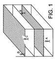
- FIG. 1is a perspective view of a group of individuals dispersed in a building.
- FIG. 2is an illustration of a group of individuals, each of which is carrying a mobile communications device in accordance with a preferred embodiment of the present invention, as a constellation of points in three-dimensional space.
- FIG. 3is a functional block diagram of a mobile communications device in accordance with a preferred embodiment of the present invention.
- FIG. 4is a flow diagram of a process for determining relative positions of a group of networked mobile communications devices in accordance with the present invention.
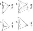
- FIGS. 5A and 5Bare true and mirror images, respectively, of a virtual constellation of the positions of the individuals of FIG. 2 .
- FIG. 6is a flow diagram of a process for determining the geometric shape defined by the actual positions of a group of networked mobiles in accordance with the present invention.
- FIG. 7is a flow diagram of a process for horizontally orienting estimated geometric shapes of a group of networked mobiles in accordance with the present invention.
- FIG. 8is a flow diagram of a process for orienting estimated geometric shapes of a group of networked mobiles with respect to azimuth.
- FIG. 9Ais constellation representative of the individuals of FIG. 2 before movement of the mobile A.
- FIG. 9Bis a constellation representative of the individuals of FIG. 2 after movement of the mobile A.
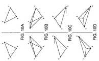
- FIGS. 10A–10Dare illustrations of the true image and mirror image virtual constellations of FIG. 2 , respectively, oriented based on movement data processing in accordance with the present invention.
- FIG. 1illustrates how a group of individuals A, B, C and D, such as police officers, firefighters, guards or soldiers, may be dispersed to locations in and around a multistory building, which is a typical environment in which GPS-based or like external electronic signal positioning systems may perform poorly or fail completely.
- each of the individuals in FIG. 2carries a mobile communications device constructed and functioning in accordance with the present invention.
- the relative positions of individuals in a mobile networked groupare determined at a mobile communications device 101 carried by each of the individuals in the group so long as the group includes at least four networked mobiles 101 .
- the relative positions determinationis performed at one mobile of the group based on collection of mobile-to-mobile range data, mobile movement data and altitude data at the one mobile, and receipt of altitude and movement data transmitted to the one mobile from each of the other mobiles in the group.
- Each of the mobilesuses the collected and received data to construct a virtual constellation having the same shape and orientation as the true constellation corresponding to the relative positions of the mobiles in the group.
- FIG. 3is a preferred embodiment of the mobile 101 in accordance with the present invention.
- the mobile 101includes a ranging transceiver module 102 , a movement assessment module 103 , a data transceiver module 104 , a position processing module 105 and a position display module 106 .
- the data transceiver module 104is coupled to each of the ranging transceiver module 102 , the movement assessment module 103 and the position processing module 105 .
- the position processing module 105is coupled to the position display module 106 and the movement assessment module 103 .
- the ranging module 102is coupled to an antenna 120 and the data transceiver module 104 is coupled to an antenna 122 .
- each of the modules of the inventive mobile 101which are described below as performing data processing operations, constitutes a software module or, alternatively, a hardware module or a combined hardware/software module.
- each of the modulessuitably contains a memory storage area, such as RAM, for storage of data and instructions for performing processing operations in accordance with the present invention.
- instructions for performing processing operationscan be stored in hardware in one or more of the modules.
- the modules of the mobile 101can be combined, as suitable, into composite modules.
- the antennae 120 and 122which are conventional devices well known in the prior art, can be combined into a single integral antenna, as is also well known in the art.
- the ranging transceiver module 102which includes a conventional wireless, such as a radio frequency (“RF”) signal, receiver and transmitter, collects data for determining the distance between the mobile in which it is contained and each of the other mobiles in the networked group.
- the transceiver module 102establishes, via the antenna 120 , a radio ranging link 107 between itself and the transceiver module 102 of another mobile. Based on the radio raging links, the transceiver module 102 of the subject mobile measures the signal transit time between itself and the ranging transceiver modules of other respective mobiles in the group. From the signal time transit data, the range between two mobiles is readily computed using well known techniques.
- RFradio frequency
- the ranging transceiver moduleuses an RF carrier modulated by a high rate PN sequence for ranging.
- the signal used for rangingis an ultrawideband (“UWB”) signal.
- UWBis advantageous because: (1) it provides virtually infinite frequency diversity, thus ensuring that the ranging signal can penetrate a wide variety of common building materials; (2) UWB signals have a low probability of detection and intercept; (3) the narrow pulse widths (500 psec) used in UWB allows for ranging accuracies to less than one foot; (4) and UWB signals can be used anywhere in the world without having to fit into or coordinate with local civilian and military frequency allocation plans.
- the movement assessment module 103includes an electronic compass and measures movement of the subject mobile in terms of distance and direction. In a preferred embodiment, the module 103 determines whether the mobile is not moving, moving in an unknown direction or moving in a known direction. In cases where a mobile is moving in a known direction, the movement assessment module 103 determines the direction. Further, the movement assessment module 103 measures the altitude of the subject mobile with respect to a reference altitude that is set when the mobile is initialized for use. In a preferred embodiment, the module 103 includes a barometric altimeter, such as commonly included in a Swiss army watch or portable GPS receivers, that uses pressure differences to measure relative altitude with respect to the altitude of a common calibration point which is set as the reference altitude.
- a barometric altimetersuch as commonly included in a Swiss army watch or portable GPS receivers
- the data transceiver module 104which includes a conventional wireless, such as an RF signal, receiver and transmitter, exchanges, via the antenna 122 , information between itself and the data transceiver modules 104 of other networked mobiles of the group.
- the data module 104 at each mobiletransmits its altitude and movement measurements to the other mobiles via wireless data links 108 established between itself and the data transceiver modules 104 of the various mobiles.
- a ranging transceiver module of a subject mobilecannot directly measure mobile-to-mobile distance to another mobile, that other mobile, or alternatively another of the mobiles of the group, conveys this ranging information to the subject mobile over a wireless data link 108 established between its data transceiver module and the data transceiver module 104 of the subject mobile.
- the position processing module 105retrieves the ranging data from the module 102 , the movement and altitude data collected at the module 103 and any range and the altitude data received at the module 104 to compute, as discussed in detail below, the relative positions of the networked mobiles.
- the position display module 106displays the relative positions of the networked mobiles which are computed at the processing module 105 .
- the module 106includes a display unit resembling an oversized ruggedized PDA.
- the module 106is not included in selected mobiles of a group.
- the mobile of the present inventionincludes a first component structure, which does not include the antennae 120 and 122 and the movement assessment module 103 , is approximately the size of a cordless telephone handset and is configured to be worn on or attached to an article of clothing.
- the movement assessment module 103is embodied as a second component structure, preferably the same size or smaller than a cordless telephone handset and configured for attachment to a belt or belt loops on pants.
- the antennae 120 and 122are embodied as a third component structure, preferably readily attachable to a shirt collar.
- the first, second and third component structures of the mobileare electronically coupled to one another.
- the mobile component structuresare configured to be carried in a holster to provide for easy removal for use.
- the position display module 106contains an electronic compass module (not shown).
- the compass moduleincludes an electronic compass, which is a different electronic compass than the electronic compass included in the movement assessment module 103 .
- the compass moduleprocesses the relative position data generated by the module 105 and suitably provides control signals to the display module 106 so that a graphical display of the computed relative positions is rotated to orient the displayed relative positions with the corresponding features in the actual environment, even if the display is pointed in different directions.
- FIG. 4is a high level flow process 150 illustrating measurement and collection of data and computations performed at each of the mobiles of a group of wirelessly networked mobiles, in accordance with the present invention, to determine the relative positions of the mobiles of the group.
- FIG. 4For purposes of illustrating the process 150 and the processes corresponding to steps of the process 150 which are described in further detail in the text accompanying the description of FIGS. 6–8 , reference is made to the individuals A, B, C and D shown in FIG. 2 each of whom is carrying a mobile 101 . Also, for ease of reference, the individuals of the group shown in FIG. 2 are referred to below as mobiles A, B, C, and D.
- each of the mobiles 101is in the form of a three part, electronically coupled unit including (i) a first unit of a movement assessment module 103 , which is worn on the belt of an individual to ensure that an accelerometer within the movement assessment module 103 can sense foot steps, i.e., movement; (ii) a second unit of the antennae 120 and 122 , which is worn on an upper portion of an individual's body to maximize signal transmission and reception capability; and (iii) a third unit containing the modules 102 , 104 , 105 and 106 and which can be worn virtually anywhere on the body of an individual.
- each ranging transceiver module 102measures mobile-to-mobile distance with respect to each of the mobiles in the group and stores in its memory the range with an associated time stamp.
- the data transceiver module 104 in a first mobilesuch as the mobile A, receives time stamped mobile-to-mobile range data from a second mobile, such as the mobile B or alternatively the mobiles C or D, based on mobile-to-mobile distance measurements made by the second mobile B with respect to first mobile A.
- the position processing module 105uses the locally or the remotely measured mobile-to-mobile distances to computer a mirror-image pair of geometric shapes or virtual constellations 201 A and 201 B.
- One of the constellationsis congruent to the actual true geometric shape 205 defined by the positions of the individual mobiles within the group and shown in FIG. 4 at step 160 , which is discussed in detail below.
- a mobilecomputes a virtual constellation of the estimated positions that has the same shape as the true constellation of the actual positions of the mobiles of the group.
- the range informationpermits that, to within a reflection, the geometric shape defined by the positions of the individual mobiles within the group can be determined.
- the virtual constellation that the position processing module 105 in a mobile determines based on the mobile-to-mobile range informationis in an arbitrary orientation that exhibits yaw, pitch, and roll with respect to the orientation of the true constellation. It is not possible to determine the orientation (yaw, pitch, roll) or absolute position (x, y, z) or (latitude, longitude, altitude) of this geometric shape solely based on the range information.
- the virtual constellationhas an unobservable virtual North-South (“N-S”) axis such that, when the virtual constellation is correctly oriented with respect to the true constellation, the virtual N-S axis will be parallel to the true N-S axis. Yaw is the angle, measured in the horizontal plane, between the true and virtual N-S axes.
- the virtual constellationhas an unobservable virtual up-down (U-D) axis, such that when the constellation is correctly oriented, the virtual U-D will be parallel to the true U-D axis.
- Pitchis the angle, measured in the vertical North-South plane, between the true and virtual U-D axes.
- Rollis the angle, measured in the verical East-West plane, between the true and virtual U-D axes.
- Steps 156 , 158 and 160 of the process 150provide, in accordance with the present invention, that any potential reflective ambiguity of the two constellations is resolved and that the proper orientation of the geometric shape is determined without the use of GPS information.
- the position processing module 105 in each of the mobilescollects movement and altitude data and stores such data with an associated time stamp in its memory.
- the mobiles of a groupshare their respective movement and altitude measurement data with one another via the wireless communication links 108 generated by the respective data transceiver modules 104 .
- step 158the position processing module 105 uses the locally and the remotely measured altitude data to determine, for each of the two images corresponding to the pair of virtual constellations, the proper orientation with respect to the horizontal plane.
- the result of applying horizontal orientation processingis a mirror-image pair of virtual constellations 203 A and 203 B which are oriented in pitch and roll.
- each position processing module 105uses the locally and the remotely measured movement data to select the correct image from the mirror-image pair of virtual constellations and to determine the proper orientation of the selected image with respect to azimuth.
- the position display module 106provides output representative of the relative positions of the mobiles of the group, which were determined in step 160 , on a monitor device.
- the mobilecontinuously tracks the positions of the individuals within the group and displays these positions on a handheld device that resembles a large PDA.
- the position processing module 105routes the relative positions data representative of the true constellation to the data transceiver module 104 and the module 104 transmits, via the antenna 122 , the relative positions of the mobiles to a remote command post.
- the ranging transceiver module 102 in each mobile of the groupcommunicates with each of the other mobiles in the group to determine straight-line distance between the subject mobile and each of the other mobiles.
- the ranging transceiver module in mobile Atransmits a time encoded wireless signal, such as an RF signal, to the mobile B. Based on this transmission, the ranging transceiver module of the mobile B can measure the time it takes for an RF signal to propagate from the ranging transceiver module of the mobile A to the ranging transceiver module of the mobile B.
- the ranging transceiver module 102 in the mobile Bcollects the suitable propagation time data
- its data transceiver module 104transmits this propagation time data to the data transceiver module 104 of the mobile A on an RF carrier signal.
- the mobiles A, B, C and D in the groupthus, in step 152 operate cooperatively in a network to collect the propagation time data necessary for determining the distances from each mobile to every other mobile in the group.
- the position processing module at a mobilecomputes the distance between the mobile A and each of the mobiles B, C and D. Based only on the mobile-to-mobile distance measurements at each of the mobiles of the group, and without any known fixed reference positions, the position processing module constructs a mirror-image pair of geometric shapes or virtual constellations which are defined by the positions of the individual mobiles within the group. If the distance measurements are exact, the pair of shapes will match exactly. In a practical system, however, some measurement error is likely.
- the virtual constellationshave a shape that is an optimal estimate of the shape of the true constellation of the actual positions of the mobiles of the group.
- FIGS. 5A and 5Billustrate, respectively, a true image constellation 203 A and a mirror image constellation 203 B for the mobiles A, B, C and D as shown in FIG. 2 .
- the constellation 203 Awhich for purposes of the example is the true geometric shape, matches the actual geometric shape of all of the mobiles in the group.
- FIG. 5Awhich is the image of the virtual constellation pair representative of the true constellation corresponding to the mobiles shown in FIG. 2
- the sequence of mobiles D, C and Bis clockwise when viewed from mobile A.
- the sequence of mobiles D, C and Bis counterclockwise when viewed from mobile A.
- the position processing module of a mobileuses the collected range information which has some measurement error, performs a linearized least squares computation to estimate the geometric shape defined by the positions of the various mobiles within a group.
- the use of a least squares computationgenerates an optimal estimate of the geometric shape in the presence of imperfect range measurements, because this estimate has the least squared range error of all the possible estimates that can be made from a set of imperfect measurements.
- the position processing modulearbitrarily establishes a local coordinate system to facilitate the estimation. Within this local coordinate system, a pair of mobiles or nodes designated node N P and node N Q are located respectively at coordinate positions (x P , y P , z P ) and (x Q , y Q , z Q ).
- the linear least squares computationrequires an equation for range estimation error that is linear in the coordinates.
- Equation (1)can be linearized by generating a truncated Taylor series expansion about the estimated positions (x P , y P , z P ) and (x Q , y Q , z Q ).
- the seriesis truncated to eliminate all second and higher order terms to yield
- r PQr PQ + x Q - x P ⁇ PQ ⁇ ⁇ x Q + y Q - y P ⁇ PQ ⁇ ⁇ x Q + z Q - z P ⁇ PQ ⁇ ⁇ x Q + x P - x Q ⁇ PQ ⁇ ⁇ x P + y P - y Q ⁇ PQ ⁇ ⁇ x P + z P - z Q ⁇ PQ ⁇ ⁇ x P ( 2 )
- R PQ⁇ PQ ⁇ r PQ and restate Equation (2) as
- R PQ⁇ x Q - x P ⁇ PQ ⁇ ⁇ x Q + y Q - y P ⁇ PQ ⁇ ⁇ x Q + z Q - z P ⁇ PQ ⁇ ⁇ x Q + ⁇ x P - x Q ⁇ PQ ⁇ ⁇ x P + y P - y Q ⁇ PQ ⁇ ⁇ x P + z P - z Q ⁇ PQ ⁇ ⁇ x P ( 3 )
- the shapeis estimated by using the positions of three mobiles to define the axes of the local coordinate system in a particular way.
- the local nodei.e., the particular mobile performing the estimation, designated node N 0
- the first remote node that the local node is able to rangeis designated as node N 1 .
- N 2The second remote node that the local node is able to range.
- R 1 , 2x 1 - x 2 ⁇ 1 , 2 ⁇ ⁇ x 1 + x 2 - x 1 ⁇ 1 , 2 ⁇ ⁇ x 2 + y 2 ⁇ 1 , 2 ⁇ ⁇ y 2
- the range estimation error from one unconstrained remote node to anotherwill include all six terms shown in Equation (3).
- ⁇ 0[ x 1 r 0 , 1 0 0 0 0 0 x 2 r 0 , 2 y 2 r 0 , 2 x 3 r 0 , 3 y 3 r 0 , 3 z 3 r 0 , 3 ⁇ x N - 1 r 0 , N - 1 y N - 1 r 0 , N - 1 z N - 1 r 0 , N - 1 ]
- ⁇ 1[ x 1 - x 2 ⁇ 1 , 2 x 2 - x 1 ⁇ 1 , 2 y 2 ⁇ 1 , 2 0 0 0 ... 0 0 0 0 0 x 1 - x 3 ⁇ 1 , 3 0 0 x 3 - x 1 ⁇ 1 , 3 y 3 ⁇ 1 , 3 z 3 ⁇ 1 , 3 ... 0 0 0 0 ⁇ ⁇ x
- ⁇ k[ 0 k
- the system of equationswill be overspecified for systems involving five or more nodes.
- the position processing module 105 in a mobileperforms a computation process 200 , as shown in FIG. 6 , to construct the virtual constellations.
- the position processing module 105assumes a set of starting position estimates (x,y,z) for each of the nodes in the group.
- Node N ois constrained to lie at (0,0,0).
- Node N 1is started at (r max ,0,0) where r max is the maximum distance at which ranging can be performed.
- Node N 2is started at (r max ,r max ,0) and all other nodes are started at (r max ,r max ,r max ).
- step 212the position processing module 105 repeats steps 202 , 204 , 206 , 208 for a predetermined number of iterations or until the RMS value of the adjustment vector falls below some predetermined threshold.
- the estimated positions (x k ,y k ,z k )are the estimated positions of the nodes which define one image of the mirror-image pair of geometric shapes corresponding to the shape defined by the positions of the individual mobiles within the group, such as shown in FIG. 5A .
- the position processing module 105generates a second image in the mirror-image pair, such as shown in FIG.
- altitude data measured at each of the mobiles and then communicated to the other mobiles of the networked groupis used in step 158 or the process 150 to orient the virtual constellation, such as determined by the process 200 performed at step 154 of the process 150 , with respect to the true horizontal plane.
- the virtual constellationis rotated in virtual space to find the orientation of the virtual constellation that results in the best fit of virtual relative altitudes to measured relative altitudes. In this orientation, the pitch and roll of the virtual constellation is approximately zero.
- a virtual constellation that has been so alignedis referred to as a pitch-and-roll aligned (“PRA”) constellation.
- PRApitch-and-roll aligned
- the optimization of the fitis preferably performed using at least one of a linear least squares estimation, a non-linear least squares estimation, a minimum mean squared error estimation, a method of moments estimation, a maximum likelihood estimation and a minimum variance estimation, which are well known mathematical techniques for optimizing an estimation.
- FIG. 7illustrates an exemplary process 250 for horizontally orienting the pair of mirror image constellations obtained in accordance with the present invention based on altitude data collected at the movement assessment module at each mobile of a networked group and without using any GPS fixes.
- the position processing module 105 of a mobilesuch as the mobile A of FIG. 2 , defines a virtual constellation of N discrete points in three-dimensional space in the form of an N ⁇ 3 matrix C. Each row of C represents one point, and the column entries are the x, y, and z coordinates of the points.
- the equation asin ⁇ has two solutions for ⁇ in the range ⁇ to ⁇ . If this primary value is designated as ⁇ 0 , then the second value can be obtained as
- the original virtual constellationis double-rotated four different ways corresponding to the four different combinations of ⁇ and ⁇ : ( ⁇ 0 , ⁇ 0 ), ( ⁇ 0 , ⁇ 1 ), ( ⁇ 1 , ⁇ 2 ) and ( ⁇ 1 , ⁇ 3 ).
- the double-rotation that results in the smallest mean-squared altitude erroris deemed to be the correct rotation.
- the virtual constellations 203are subsequently rotated around the z axis to bring virtual azimuths observed in the constellations into alignment with azimuths measured in the actual deployment of the mobiles of the group to yield a single virtual constellation 205 that is properly oriented in yaw, pitch and roll.
- the networked mobiles of a groupfurther include GPS capability and exchange information as to their relative positions with respect to the other mobiles of the group.
- Two GPS receivers working cooperativelycan each obtain a position fix when, together, they can receive the direct path from as few as three satellites, provided that there are a total of at least five receivable satellite-to-receiver direct paths. See “Method and System for Determining Absolute Positions of Mobile Communications Devices Using Remotely Generated Positioning Information,” U.S. Ser. No. 10/639,022, filed Aug. 11, 2003 and assigned to the assignee of this application, incorporated by reference herein.
- the movement assessment module 103includes an electronic pedometer, such as described in U.S. Pat. No. 5,583,776, incorporated by reference herein, as well as an electronic compass and a barometric altimeter.
- the movement assessment module 103uses the pedometer in conjunction with the compass to determine the distance and direction the mobile moves when the individual carrying the mobile walks or runs in a forward direction, as such forward movements generally are accurate measurements of movement.
- the movement assessment module 103distinguishes when the individual is stationary or moving in some manner other than forward walking or running and discards these measurements.
- the present inventiontracks mobile positions without requiring accurate estimates of direction and distance traveled when the individual is moving in some manner other than normal forward walking or running.
- the movement assessment moduleincludes an altimeter, a solid state electronic compass and three accelerometers.
- One of the accelerometersis mounted vertically and configured to act as a pedometer for detecting the foot impacts generated while walking, as is known in the art.
- the other two accelerometersare mounted horizontally, one oriented front-to-back and the other one oriented left-to-right.
- the measurements performed at the horizontal accelerometersare used to screen the foot impact indications provided by the vertical accelerometer to provide that normal forward walking or running can be distinguished from all other movements.
- the average azimuth indicated by the electronic compassis a good estimate of the direction of travel.
- FIG. 9Aillustrates the original constellation 203 A of the mobiles A, B, C and D of FIG. 2 before movement
- FIG. 9Billustrates a constellation 203 AA in which the mobile A has moved while the mobiles B, C, and D remain fixed.
- the constellation corresponding to the end of the movement intervalis rotated in azimuth until the movement vector of the individual has a virtual azimuth that agrees with the azimuth measured by the electronic compass in the mobile of the individual.
- the rotationeffectively orients the entire constellation for all of the individuals in the group. It is noted that any single measurement will include some measurement error and, therefore, in a preferred embodiment, the computation includes a best-fit rotation based on multiple simultaneous movements reported by different mobiles. In a further preferred embodiment, the optimal rotation for a single yaw adjustment opportunity is found using least squares estimation techniques.
- an angular rotationis estimated for orienting the horizontally oriented virtual constellation by performing at least one of a linear least squares estimation, a non-linear least squares estimation, a minimum mean squared error estimation, a method of moments estimation, a maximum likelihood estimation and a minimum variance estimation, which are well know techniques for optimizing an estimation.
- the position of mobile unit k at time t 1is (X k (t 1 ),y k (t 1 )) and the position at time t 2 is (X k (t 2 ),y k (t 2 )).
- the frequency and duration of opportunities to adjust the yaw of the PRA constellationswill vary.
- a yaw adjustment opportunityoccurs whenever there are intervals of time, e.g., several seconds, over which one or more individuals with mobiles perform regular movement while several other individuals with mobiles are not moving.
- the movement assessment modulemonitors movement status of the individual at any instant and categorizes the status as: (1) not moving; (2) regular movement for which a direction and a distance can be measured with high confidence; (3) quasi-regular movement for which a direction and distance can be measured with reduced confidence; and (4) irregular movement for which direction and/or distance cannot be reliably measured. For example, an electronic compass of an individual measures whether an individual regularly moves in a certain direction.
- the position of this individual relative to the non-moving individualsis determined at the beginning and the end of the regular movement interval. These two positions define the beginning and end of the individual's line of apparent regular movement, or movement vector (“MV”), through the fixed background of the constellation.
- MVmovement vector
- several different azimuths and movement vectorscan be obtained. If all of the movement measurements were perfect, one azimuthal rotation of the virtual constellation would bring each of the movement vectors into alignment with its corresponding measured azimuth. In reality, the measurements will not be perfect and each MV azimuth pair may indicate a different amount of azimuth rotation is needed to bring the PRA constellation into alignment.
- the movement assessment moduleincludes an inclinometer which collects information to permit the movement assessment module to distinguish between the individuals' movements in erect and prone positions.
- t z[ cos ⁇ ⁇ ⁇ - sin ⁇ ⁇ ⁇ ]
- C a[ x 1 ⁇ ( t 2 ) - x 1 ⁇ ( t 1 ) y 1 ⁇ ( t 2 ) - y 1 ⁇ ( t 1 ) x 2 ⁇ ( t 2 ) - x 2 ⁇ ( t 1 ) y 2 ⁇ ( t 2 ) - y 2 ⁇ ( t 1 ) ⁇ ⁇ x k ⁇ ( t 2 ) - x k ⁇ ( t 1 ) y k ⁇ ( t 2 ) - y k ⁇ ( t 1 ) - [ y 1 ⁇ ( t 2 ) - y 1 ⁇ ( t 1 ) ] x 1 ⁇ ( t 2 ) - x 1 ⁇ ( t 1 ) - [ y 2 ⁇ ( t 2 ) - y 1
- step 308the position processing module 105 determines the angle ⁇ by which the virtual constellation must be rotated as
- FIGS. 10A–10Dillustrate changes to the mirror image virtual constellations of the group of mobiles of FIG. 2 , which have been determined and horizontally oriented in accordance with the present invention based on movement measurements made during a yaw adjustment opportunity and which lead to resolution of the ambiguity in the virtual constellations in accordance with the present invention.
- a yaw adjustment opportunityoccurs, for example, when the mobile A moves a distance at a bearing of 90 degrees as measured by the electronic compass contained in the mobile A.
- FIG. 10Bshows the two movement AC and AB vectors and the two constellation images as shown in FIG. 10B .
- the two constellation images in FIG. 10 Bstill exhibit mirror-image symmetry.
- FIG. 10Cshows the two constellation images rotated so that each movement vector points to the right to signify the yaw adjusted versions of these constellation images.
- a second yaw adjustment opportunityoccurs when the mobile B moves some distance at a bearing of zero degrees as measured by its electronic compass.
- This movementresults in new range measurements for links BC and BA, producing the movement vectors and the two constellation images as shown in FIG. 10D .
- the movement vector in the left-hand image in FIG. 10Dpoints North and is consistent with the bearing measured by the compass of the mobile B.
- the movement vector in the right-hand imagepoints South and conflicts with the measured bearing, thus allowing the right-hand image to be rejected as incorrect.
- a movement vectorcan only be determined for mobiles engaged in regular or quasi-regular movement.
- the position processing moduleaccounts for the circumstance where the pattern of movements exhibited by the group of mobiles is such that yaw adjustment opportunities occur very infrequently. If too much time passes without a yaw adjustment, the position processing module declares the orientation of the virtual constellation stale and, therefore, unsuitable for deriving absolute bearing information for display to individual members of the group. Although the relative positions of nearby individuals still can be displayed under these conditions, the relative positions information in these displays is not tied to absolute directions and, instead, is referenced to the apparent direction of the movement vector for the individual wearing the display. Thus, if a mobile is not moving, or is engaged in movement that the movement assessment module deems to be irregular, the most recent satisfactory movement vector is retained as the reference until such time that it becomes possible to compute a new movement vector.
- the position display module 106expresses the relative positions of the mobiles of the networked group in the form of a compass bearing and relative distances from each mobile to all other mobiles within the networked group. In a further preferred embodiment, the position display module 106 , based on the computed relative positions, determines absolute positions of the mobiles relative to Universal Transverse Mercator coordinates or latitude and longitude.
- the mobile of the present inventionincludes long-haul radio communication capabilities at the data transceiver module, as known in the art, and communicates the computed relative position information to another communications device, such as a remotely located communications base unit.
- the mobile 101is a benchmark unit including full GPS capability.
- the benchmark mobileis preferably deployed in locations, such as vacant lots or rooftops, that have good visibility of a GPS constellation.
- the benchmark mobileuses its GPS capability, as well known in the art, to determine its position with respect to both latitude and longitude and with respect to the other team members based on the relative position information provided by any of the mobiles of the group. Based on this information, the benchmark mobile computes the absolute position of each team member relative to the benchmark.
- the groupmust include a benchmark mobile such that the total of mobiles plus benchmark mobiles is at least four to provide that the relative positions can be computed in accordance with the present invention.
- one of the mobiles in a group of networked mobiles of the preset inventionis a benchmark mobile which is intentionally placed in a fixed position
- the benchmark mobileprovides an additional reference point that aids the other mobiles to determine their relative positions as they maneuver. If the GPS capabilities of the benchmark mobile are not available for use, the benchmark mobile provides a stationary node in the constellation to aid in the smooth evolution of the virtual constellation as the true deployment undergoes rapid changes.
- a benchmark mobileis placed at a nexus of propagation paths of the group of mobiles and relays data and ranging signals between mobiles that otherwise are unable to communicate with or range each other. For example, a benchmark mobile would be placed at a turn in a tunnel complex being searched by a squad of soldiers.
- the benchmark mobilecontains long-haul radio communication capabilities for transmitting the computed relative locations of the mobiles of the group to a remote command post.
Landscapes
- Engineering & Computer Science (AREA)
- Computer Networks & Wireless Communication (AREA)
- Signal Processing (AREA)
- Physics & Mathematics (AREA)
- General Physics & Mathematics (AREA)
- Radar, Positioning & Navigation (AREA)
- Remote Sensing (AREA)
- Position Fixing By Use Of Radio Waves (AREA)
- Mobile Radio Communication Systems (AREA)
Abstract
Description
ρPQ=√{square root over ((xQ−xP)2+(yQ−yP)2+(zQ−zP)2)}{square root over ((xQ−xP)2+(yQ−yP)2+(zQ−zP)2)}{square root over ((xQ−xP)2+(yQ−yP)2+(zQ−zP)2)} (1)
The linear least squares computation requires an equation for range estimation error that is linear in the coordinates. Equation (1) can be linearized by generating a truncated Taylor series expansion about the estimated positions (xP, yP, zP) and (xQ, yQ, zQ). The series is truncated to eliminate all second and higher order terms to yield
where rPQis the measured range between node NPand node NQ. It is convenient to define the range estimation error as RPQ=ρPQ−rPQand restate Equation (2) as
The second remote node that the local node is able to range is designated as node N2. This node is placed in the x-y plane of the local coordinate system, so z2=0 and the range estimation error for N0and N2simplifies to
The range estimation error for N1and N2simplifies to
The range estimation error from node N1to an unconstrained node simplifies to the form
The range estimation error from node N2to an unconstrained node simplifies to the form
The system of equations for range estimation error can be put in matrix form as
R=αd (4)
where
and the submatrices α0through αN-2are configured as shown below
For the general case of N>2 nodes, the number of range equations will be
and the number of unknown coordinates will be
Nunk=3(N−2)
The system of equations will be overspecified for systems involving five or more nodes. When the system is overspecified, the best solution in a least squares sense can be found using the normal equation to solve Equation (4) for d where
d=[αTα]−1αTR (6)
ρi,j=√{square root over ((xi−xj)2+(yi−yj)2+(zi−zj)2)}{square root over ((xi−xj)2+(yi−yj)2+(zi−zj)2)}{square root over ((xi−xj)2+(yi−yj)2+(zi−zj)2)} (1)
and forms the a matrix in accordance with Equation (5) and the equations for the submatrices α0through αN-2discussed above.
Ri,j=ρi,j−ri,j
d=[αTα]−1αTR (6)
(xk)new=(xk)old+∂xkK=1,2, . . . , N−1
(yk)new=(xk)old+∂xkK=2,3, . . . , N−1
(zk)new=(xk)old+∂XkK=3,4, . . . , N−1
z=Ct2 (7)
where
zm=Ct2
where zmis the vector of measured altitudes referenced to the measured altitude of the local mobile unit. This solution is readily found as
tz=[CTC]−1CTzm (8)
and the result obtained from Equation (8) will be a three-element column vector
φ=sin−1α
For −1<a <1, the equation a =sin φ has two solutions for φ in the range −π to π. If this primary value is designated as φ0, then the second value can be obtained as
For −1<b <1, the equation b =sin θcos φ will have four solutions for θ in the range −π to π. There will be two solutions for θfor each of the two possible values of φ:
The original virtual constellation is double-rotated four different ways corresponding to the four different combinations of φ and θ: (φ0, θ0), (φ0,θ1), (φ1, θ2) and (φ1, θ3). The double-rotation that results in the smallest mean-squared altitude error is deemed to be the correct rotation.
Orienting the Virtual Constellation with Respect to Azimuth
θ=90−A
A=90−θ
If the mobile A moves a distance of r at an azimuth of A, the x and y components of this movement are
dx=r cosθ=r sin A
dy=r sinθ=r cos A
Within the virtual constellation, the position of mobile unit k at time t1is (Xk(t1),yk(t1)) and the position at time t2is (Xk(t2),yk(t2)).
da=


dm=
daTz=dm
where
This result can be extended to the case of k mobiles moving during the time interval from t1to t2:
DaTz=Dm (11)
where
When Daand Dmare known, it is possible to use least squares techniques to solve for Tzyielding
When solved in this unconstrained form, the constraints implied by Equation (12) of a=d, c=−b and a2+b2=1 may not be enforced. To eliminate redundant elements in Tz, Equation (11) can be reformulated such that the rotation matrix becomes a 2-element column vector:
Catz=Cm (13)
where
Least squares methods can be used to solve Equation (13) for tzas:
tz=[CaTCa]−1CaTCm
which yields
As a=cosψ and b=sinψ, in
Claims (37)
Priority Applications (1)
| Application Number | Priority Date | Filing Date | Title |
|---|---|---|---|
| US10/641,588US7031725B2 (en) | 2002-08-13 | 2003-08-11 | Method and system for determining relative positions of networked mobile communication devices |
Applications Claiming Priority (2)
| Application Number | Priority Date | Filing Date | Title |
|---|---|---|---|
| US40296402P | 2002-08-13 | 2002-08-13 | |
| US10/641,588US7031725B2 (en) | 2002-08-13 | 2003-08-11 | Method and system for determining relative positions of networked mobile communication devices |
Publications (2)
| Publication Number | Publication Date |
|---|---|
| US20040033808A1 US20040033808A1 (en) | 2004-02-19 |
| US7031725B2true US7031725B2 (en) | 2006-04-18 |
Family
ID=31715914
Family Applications (1)
| Application Number | Title | Priority Date | Filing Date |
|---|---|---|---|
| US10/641,588Expired - LifetimeUS7031725B2 (en) | 2002-08-13 | 2003-08-11 | Method and system for determining relative positions of networked mobile communication devices |
Country Status (7)
| Country | Link |
|---|---|
| US (1) | US7031725B2 (en) |
| EP (1) | EP1530882A1 (en) |
| JP (1) | JP2005535886A (en) |
| AU (1) | AU2003265400A1 (en) |
| CA (1) | CA2495227A1 (en) |
| PL (1) | PL375234A1 (en) |
| WO (1) | WO2004016009A1 (en) |
Cited By (83)
| Publication number | Priority date | Publication date | Assignee | Title |
|---|---|---|---|---|
| US20040212533A1 (en)* | 2003-04-23 | 2004-10-28 | Whitehead Michael L. | Method and system for satellite based phase measurements for relative positioning of fixed or slow moving points in close proximity |
| US20050201300A1 (en)* | 2004-03-11 | 2005-09-15 | Raj Bridgelall | Self-configuring wireless personal area network |
| US20060121877A1 (en)* | 2004-12-03 | 2006-06-08 | Motorola, Inc. | Methods and apparatus for placement of an emergency call |
| US20070198185A1 (en)* | 2002-12-11 | 2007-08-23 | Mcclure John A | GNSS control system and method |
| US20070229356A1 (en)* | 2006-02-14 | 2007-10-04 | Kodrin David S | Devices, systems and method of determining the location of mobile personnel |
| US20070239350A1 (en)* | 2006-04-07 | 2007-10-11 | Zumsteg Philip J | Multi-function tracking device with robust asset tracking system |
| US7373231B2 (en) | 2002-12-11 | 2008-05-13 | Hemisphere Gps Llc | Articulated equipment position control system and method |
| US7388539B2 (en) | 2005-10-19 | 2008-06-17 | Hemisphere Gps Inc. | Carrier track loop for GNSS derived attitude |
| US20080147282A1 (en)* | 2006-12-15 | 2008-06-19 | Georg Kormann | Tracking system configured to determine a parameter for use in guiding an implement attached to a work machine |
| US20080269988A1 (en)* | 2003-03-20 | 2008-10-30 | Feller Walter J | Combined gnss gyroscope control system and method |
| US20090005070A1 (en)* | 2007-06-28 | 2009-01-01 | Apple Inc. | Synchronizing mobile and vehicle devices |
| US20090017837A1 (en)* | 2004-09-17 | 2009-01-15 | Kim Ii Tae | System and method for determining position of mobile communication device |
| US20090046005A1 (en)* | 2007-08-16 | 2009-02-19 | Cybernet Systems Corporation | Wireless mobile indoor/outdoor tracking system |
| US20090149202A1 (en)* | 2007-12-07 | 2009-06-11 | Christian Steele | System and method for determination of position |
| US20090251366A1 (en)* | 2008-04-08 | 2009-10-08 | Mcclure John A | Gnss-based mobile communication system and method |
| US20090300537A1 (en)* | 2008-05-27 | 2009-12-03 | Park Kenneth J | Method and system for changing format for displaying information on handheld device |
| WO2009158607A1 (en) | 2008-06-26 | 2009-12-30 | Telcordia Technologies, Inc. | Self-correcting adaptive tracking system (sats) |
| US20100023251A1 (en)* | 2008-07-25 | 2010-01-28 | Gale William N | Cost based open area maps |
| US20100023252A1 (en)* | 2008-07-25 | 2010-01-28 | Mays Joseph P | Positioning open area maps |
| US20100023250A1 (en)* | 2008-07-25 | 2010-01-28 | Mays Joseph P | Open area maps |
| US20100020093A1 (en)* | 2008-07-25 | 2010-01-28 | Stroila Matei N | Open area maps based on vector graphics format images |
| US20100021012A1 (en)* | 2008-07-25 | 2010-01-28 | Seegers Peter A | End user image open area maps |
| US20100023249A1 (en)* | 2008-07-25 | 2010-01-28 | Mays Joseph P | Open area maps with restriction content |
| US20100049469A1 (en)* | 2006-09-19 | 2010-02-25 | Lauri Wirola | Relative positioning |
| KR100946988B1 (en) | 2007-10-08 | 2010-03-10 | 전자부품연구원 | Apparatus and method for collaborative location recognition using maximum likelihood estimation including weights |
| US7689354B2 (en) | 2003-03-20 | 2010-03-30 | Hemisphere Gps Llc | Adaptive guidance system and method |
| US20100176991A1 (en)* | 2008-12-11 | 2010-07-15 | Webber Mark R | Gnss superband asic with simultaneous multi-frequency down conversion |
| US20100185366A1 (en)* | 2005-07-19 | 2010-07-22 | Heiniger Richard W | Adaptive machine control system and method |
| US20100220818A1 (en)* | 2006-05-18 | 2010-09-02 | Matsushita Electric Industrial Co., Ltd. | Digital broadcast reception device |
| US7835832B2 (en) | 2007-01-05 | 2010-11-16 | Hemisphere Gps Llc | Vehicle control system |
| US20100299065A1 (en)* | 2008-07-25 | 2010-11-25 | Mays Joseph P | Link-node maps based on open area maps |
| US20110025555A1 (en)* | 2009-07-29 | 2011-02-03 | Whitehead Michael L | System and method for augmenting dgnss with internally-generated differential correction |
| US7948769B2 (en) | 2007-09-27 | 2011-05-24 | Hemisphere Gps Llc | Tightly-coupled PCB GNSS circuit and manufacturing method |
| US8000381B2 (en) | 2007-02-27 | 2011-08-16 | Hemisphere Gps Llc | Unbiased code phase discriminator |
| US20110199917A1 (en)* | 2010-02-12 | 2011-08-18 | Jeyhan Karaoguz | Collaborative sharing of location information among devices in a network |
| US8085196B2 (en) | 2009-03-11 | 2011-12-27 | Hemisphere Gps Llc | Removing biases in dual frequency GNSS receivers using SBAS |
| US8108144B2 (en) | 2007-06-28 | 2012-01-31 | Apple Inc. | Location based tracking |
| US8140223B2 (en) | 2003-03-20 | 2012-03-20 | Hemisphere Gps Llc | Multiple-antenna GNSS control system and method |
| US8138970B2 (en) | 2003-03-20 | 2012-03-20 | Hemisphere Gps Llc | GNSS-based tracking of fixed or slow-moving structures |
| US8175802B2 (en) | 2007-06-28 | 2012-05-08 | Apple Inc. | Adaptive route guidance based on preferences |
| US8190337B2 (en) | 2003-03-20 | 2012-05-29 | Hemisphere GPS, LLC | Satellite based vehicle guidance control in straight and contour modes |
| US8204684B2 (en) | 2007-06-28 | 2012-06-19 | Apple Inc. | Adaptive mobile device navigation |
| US20120184287A1 (en)* | 2011-01-19 | 2012-07-19 | Qualcomm Incorporated | Methods and apparatus for mobile device based location determination in a communications system |
| US8260320B2 (en) | 2008-11-13 | 2012-09-04 | Apple Inc. | Location specific content |
| US8271194B2 (en) | 2004-03-19 | 2012-09-18 | Hemisphere Gps Llc | Method and system using GNSS phase measurements for relative positioning |
| US8275352B2 (en) | 2007-06-28 | 2012-09-25 | Apple Inc. | Location-based emergency information |
| US8290513B2 (en) | 2007-06-28 | 2012-10-16 | Apple Inc. | Location-based services |
| US8311526B2 (en) | 2007-06-28 | 2012-11-13 | Apple Inc. | Location-based categorical information services |
| US8311696B2 (en) | 2009-07-17 | 2012-11-13 | Hemisphere Gps Llc | Optical tracking vehicle control system and method |
| US8332402B2 (en) | 2007-06-28 | 2012-12-11 | Apple Inc. | Location based media items |
| US8334804B2 (en) | 2009-09-04 | 2012-12-18 | Hemisphere Gps Llc | Multi-frequency GNSS receiver baseband DSP |
| US8355862B2 (en) | 2008-01-06 | 2013-01-15 | Apple Inc. | Graphical user interface for presenting location information |
| US8359643B2 (en) | 2008-09-18 | 2013-01-22 | Apple Inc. | Group formation using anonymous broadcast information |
| US20130030684A1 (en)* | 2010-04-12 | 2013-01-31 | Nokia Corporation | Selection of a relative positioning method |
| US8369867B2 (en) | 2008-06-30 | 2013-02-05 | Apple Inc. | Location sharing |
| US8386129B2 (en) | 2009-01-17 | 2013-02-26 | Hemipshere GPS, LLC | Raster-based contour swathing for guidance and variable-rate chemical application |
| US8385964B2 (en) | 2005-04-04 | 2013-02-26 | Xone, Inc. | Methods and apparatuses for geospatial-based sharing of information by multiple devices |
| US8401704B2 (en) | 2009-07-22 | 2013-03-19 | Hemisphere GPS, LLC | GNSS control system and method for irrigation and related applications |
| US8456356B2 (en) | 2007-10-08 | 2013-06-04 | Hemisphere Gnss Inc. | GNSS receiver and external storage device system and GNSS data processing method |
| US8548649B2 (en) | 2009-10-19 | 2013-10-01 | Agjunction Llc | GNSS optimized aircraft control system and method |
| US8583315B2 (en) | 2004-03-19 | 2013-11-12 | Agjunction Llc | Multi-antenna GNSS control system and method |
| US8583326B2 (en) | 2010-02-09 | 2013-11-12 | Agjunction Llc | GNSS contour guidance path selection |
| US8594879B2 (en) | 2003-03-20 | 2013-11-26 | Agjunction Llc | GNSS guidance and machine control |
| US8644843B2 (en) | 2008-05-16 | 2014-02-04 | Apple Inc. | Location determination |
| US8649930B2 (en) | 2009-09-17 | 2014-02-11 | Agjunction Llc | GNSS integrated multi-sensor control system and method |
| US8660530B2 (en) | 2009-05-01 | 2014-02-25 | Apple Inc. | Remotely receiving and communicating commands to a mobile device for execution by the mobile device |
| US8666367B2 (en) | 2009-05-01 | 2014-03-04 | Apple Inc. | Remotely locating and commanding a mobile device |
| US8670748B2 (en) | 2009-05-01 | 2014-03-11 | Apple Inc. | Remotely locating and commanding a mobile device |
| US8686900B2 (en) | 2003-03-20 | 2014-04-01 | Hemisphere GNSS, Inc. | Multi-antenna GNSS positioning method and system |
| US8762056B2 (en) | 2007-06-28 | 2014-06-24 | Apple Inc. | Route reference |
| US8774825B2 (en) | 2007-06-28 | 2014-07-08 | Apple Inc. | Integration of map services with user applications in a mobile device |
| US9002566B2 (en) | 2008-02-10 | 2015-04-07 | AgJunction, LLC | Visual, GNSS and gyro autosteering control |
| US9066199B2 (en) | 2007-06-28 | 2015-06-23 | Apple Inc. | Location-aware mobile device |
| US9109904B2 (en) | 2007-06-28 | 2015-08-18 | Apple Inc. | Integration of map services and user applications in a mobile device |
| US9250092B2 (en) | 2008-05-12 | 2016-02-02 | Apple Inc. | Map service with network-based query for search |
| US20160249158A1 (en)* | 2015-02-19 | 2016-08-25 | Xerox Corporation | System and method for flexibly pairing devices using adaptive variable thresholding |
| US9702709B2 (en) | 2007-06-28 | 2017-07-11 | Apple Inc. | Disfavored route progressions or locations |
| US9880562B2 (en) | 2003-03-20 | 2018-01-30 | Agjunction Llc | GNSS and optical guidance and machine control |
| USRE47101E1 (en) | 2003-03-20 | 2018-10-30 | Agjunction Llc | Control for dispensing material from vehicle |
| USRE48527E1 (en) | 2007-01-05 | 2021-04-20 | Agjunction Llc | Optical tracking vehicle control system and method |
| US20210266713A1 (en)* | 2012-12-26 | 2021-08-26 | Truemotion, Inc. | Methods and systems for driver identification |
| US11148659B2 (en)* | 2017-06-08 | 2021-10-19 | Caterpillar Sarl | Stability of work machines |
| US20230214791A1 (en)* | 2020-07-27 | 2023-07-06 | BlueOwl, LLC | Method for creating and maintaining a distributed ledger of vehicle gas consumption and wear and tear information |
Families Citing this family (56)
| Publication number | Priority date | Publication date | Assignee | Title |
|---|---|---|---|---|
| KR100690736B1 (en)* | 2003-11-25 | 2007-03-09 | 엘지전자 주식회사 | Mobile communication terminal with WPS function |
| US20050176441A1 (en)* | 2004-02-06 | 2005-08-11 | Jurecka Joseph W. | Method and apparatus for locating mobile stations in a wireless telecommunications system |
| US7403744B2 (en)* | 2004-03-11 | 2008-07-22 | Symbol Technologies, Inc. | Self-associating wireless personal area network |
| JP4111165B2 (en)* | 2004-05-07 | 2008-07-02 | ソニー株式会社 | Portable electronic device, wireless communication system and wireless connection control method thereof |
| US7248211B2 (en)* | 2004-07-26 | 2007-07-24 | Navcom Technology Inc. | Moving reference receiver for RTK navigation |
| NL1026919C2 (en)* | 2004-08-27 | 2006-02-28 | Nedap Agri B V | Ultra-wide-band system for determining animals. |
| US20060265664A1 (en)* | 2005-05-17 | 2006-11-23 | Hitachi, Ltd. | System, method and computer program product for user interface operations for ad-hoc sensor node tracking |
| US20060276205A1 (en) | 2005-06-01 | 2006-12-07 | Henrik Bengtsson | Wireless communication terminals and methods that display relative positions of other wireless communication terminals |
| US7683757B2 (en)* | 2005-10-18 | 2010-03-23 | Lear Corporation | Multi-antenna system and method for remotely controlling a function |
| WO2007067831A1 (en)* | 2005-10-31 | 2007-06-14 | Terahop Networks, Inc. | Determining relative elevation using gps and ranging |
| JP2007248362A (en)* | 2006-03-17 | 2007-09-27 | Hitachi Ltd | Terminal positioning system and position measuring method |
| JP4878488B2 (en)* | 2006-03-31 | 2012-02-15 | 株式会社国際電気通信基礎技術研究所 | Wireless device and wireless network system including the same |
| US20080082263A1 (en)* | 2006-08-30 | 2008-04-03 | Harris Corporation | Position estimation method and related device |
| GB0703616D0 (en)* | 2007-02-23 | 2007-04-04 | Imp Innovations Ltd | Improved non-gps positioning systems |
| WO2008156393A1 (en)* | 2007-06-18 | 2008-12-24 | Telefonaktiebolaget Lm Ericsson (Publ) | Method and arrangement for positioning in a mobile telecommunication network |
| US8140016B2 (en)* | 2008-03-13 | 2012-03-20 | Sony Ericsson Mobile Communications Ab | Wireless communication terminals and methods using acoustic ranging synchronized to RF communication signals |
| CN102077663A (en)* | 2008-06-24 | 2011-05-25 | 爱立信电话股份有限公司 | Method for providing geographical position related information in a wireless network |
| US8614975B2 (en) | 2008-09-19 | 2013-12-24 | Qualcomm Incorporated | Synchronizing a base station in a wireless communication system |
| US9037155B2 (en)* | 2008-10-28 | 2015-05-19 | Sven Fischer | Time of arrival (TOA) estimation for positioning in a wireless communication network |
| US8982851B2 (en)* | 2009-01-06 | 2015-03-17 | Qualcomm Incorporated | Hearability improvements for reference signals |
| US8994589B2 (en)* | 2009-04-23 | 2015-03-31 | Abdelwahed Marzouki | Orientation and localization system |
| US9545222B2 (en)* | 2009-09-01 | 2017-01-17 | Adidas Ag | Garment with noninvasive method and system for monitoring physiological characteristics and athletic performance |
| US9326705B2 (en) | 2009-09-01 | 2016-05-03 | Adidas Ag | Method and system for monitoring physiological and athletic performance characteristics of a subject |
| US8688139B2 (en)* | 2009-09-10 | 2014-04-01 | Qualcomm Incorporated | Concurrent wireless transmitter mapping and mobile station positioning |
| US9091746B2 (en) | 2010-07-01 | 2015-07-28 | Qualcomm Incorporated | Determination of positions of wireless transceivers to be added to a wireless communication network |
| US10212687B2 (en)* | 2010-09-30 | 2019-02-19 | Echo Ridge Llc | System and method for robust navigation and geolocation using measurements of opportunity |
| JP5712569B2 (en)* | 2010-11-11 | 2015-05-07 | 富士通株式会社 | Moving object identification system, moving object identification device, and moving object identification program |
| US8442556B2 (en)* | 2010-12-13 | 2013-05-14 | Verizon Patent And Licensing Inc. | Detecting mobile device usage within wireless networks |
| US9462423B1 (en)* | 2011-07-12 | 2016-10-04 | Google Inc. | Qualitative and quantitative sensor fusion for indoor navigation |
| US8660582B2 (en)* | 2011-09-20 | 2014-02-25 | Steve Y. Chen | System and method for electronic communications between users in a similar geographic location |
| US8626189B2 (en)* | 2011-12-06 | 2014-01-07 | Raytheon Company | Position optimization |
| CN110006395B (en) | 2011-12-28 | 2022-03-29 | 英特尔公司 | Provision of navigation services including reporting of altitude information and/or vertical guidance |
| US8825077B2 (en)* | 2012-01-27 | 2014-09-02 | Qualcomm Incorporated | Method and system for femtocell positioning |
| EP2667280A1 (en)* | 2012-05-23 | 2013-11-27 | Nxp B.V. | Device Control System And Method Of Determining Altitude |
| US9100778B2 (en)* | 2012-11-13 | 2015-08-04 | Google Inc. | Determining a WiFi scan location |
| JP6030976B2 (en)* | 2013-02-26 | 2016-11-24 | 日本電信電話株式会社 | Wireless communication station position estimation apparatus, wireless communication station position estimation method, and wireless communication station position estimation program |
| BR112016001842A2 (en)* | 2013-07-30 | 2017-08-01 | Nokia Technologies Oy | computer methods, apparatus, and program |
| US9709672B2 (en) | 2013-08-16 | 2017-07-18 | Drnc Holdings, Inc. | Method and system for identifying and finding a range of an object |
| US9958533B2 (en)* | 2013-09-06 | 2018-05-01 | Drnc Holdings, Inc. | Method and system for locating wireless devices within a local region |
| US9052999B1 (en)* | 2013-09-11 | 2015-06-09 | Sprint Spectrum L.P. | Method and system for transmitting a determined altitude of a user equipment device located in a building |
| WO2015054866A1 (en)* | 2013-10-17 | 2015-04-23 | Nokia Technologies Oy | A relative positioning method |
| JP6174992B2 (en)* | 2013-12-20 | 2017-08-02 | 京セラ株式会社 | Portable electronic device, control method, and control program |
| US9674668B2 (en)* | 2014-03-21 | 2017-06-06 | Htc Corporation | Method, electronic apparatus and computer readable medium for determining relative position of apparatus |
| EP2924469A1 (en)* | 2014-03-27 | 2015-09-30 | Sinvent AS | Information system and method |
| KR20160028321A (en)* | 2014-09-03 | 2016-03-11 | 삼성전자주식회사 | Method for estimating a distance and electronic device thereof |
| US10079704B2 (en) | 2014-09-22 | 2018-09-18 | Drnc Holdings, Inc. | Transmission apparatus for a wireless device using delta-sigma modulation |
| FR3027409B1 (en) | 2014-10-17 | 2021-01-08 | Sagem Defense Securite | METHOD FOR THE GEOLOCATION OF MOBILE UNITS EVOLVING WITHIN A CLOSED STRUCTURE |
| US9867016B2 (en)* | 2014-11-17 | 2018-01-09 | West Corporation | System and method for locating a mobile phone with moveable wireless beacons |
| TWI582389B (en)* | 2015-10-26 | 2017-05-11 | 行政院原子能委員會核能研究所 | Navigation system for inertial positioning with gait detection method |
| CN108474835B (en) | 2015-11-25 | 2022-04-15 | 斯科特科技公司 | Indoor positioning and tracking system |
| US10412545B1 (en)* | 2016-10-24 | 2019-09-10 | Marvell International Ltd. | Device-to-device radio frequency proximity determination |
| DE102017006849A1 (en)* | 2017-07-21 | 2019-01-24 | Lukas HEINDL | Method for determining the relative positions of at least two mobile terminals relative to one another |
| US10708715B2 (en)* | 2017-10-16 | 2020-07-07 | Christopher Anthony Silva | Method and system for 3-D location of mobile devices |
| GB2574692A (en)* | 2018-04-23 | 2019-12-18 | Sportable Tech Ltd | Sports tracking |
| US11255980B2 (en)* | 2019-06-28 | 2022-02-22 | Sony Corporation | Collaborative positioning |
| US12270916B2 (en) | 2019-07-24 | 2025-04-08 | Echo Ridge Llc | System and method for aiding data processing for signals of opportunity-based assured position, navigation and timing (PNT) |
Citations (21)
| Publication number | Priority date | Publication date | Assignee | Title |
|---|---|---|---|---|
| US5301353A (en) | 1990-02-12 | 1994-04-05 | Motorola, Inc. | Communication system and apparatus |
| US5365516A (en)* | 1991-08-16 | 1994-11-15 | Pinpoint Communications, Inc. | Communication system and method for determining the location of a transponder unit |
| US5552772A (en)* | 1993-12-20 | 1996-09-03 | Trimble Navigation Limited | Location of emergency service workers |
| US5578989A (en) | 1992-12-18 | 1996-11-26 | Detection Systems, Inc. | Personal security system with system wide testing |
| US5583776A (en) | 1995-03-16 | 1996-12-10 | Point Research Corporation | Dead reckoning navigational system using accelerometer to measure foot impacts |
| US5923294A (en) | 1995-06-23 | 1999-07-13 | Thomas - Csf | Navigation system allowing real-time coordination of the displacement of mobiles travelling out of direct line of sight |
| US5974329A (en) | 1997-09-29 | 1999-10-26 | Rutgers University | Method and system for mobile location estimation |
| US6094164A (en) | 1995-06-15 | 2000-07-25 | Trimble Navigation Limited | Integrated radio direction finding and GPS receiver tracking system |
| US6154139A (en) | 1998-04-21 | 2000-11-28 | Versus Technology | Method and system for locating subjects within a tracking environment |
| US6243588B1 (en)* | 1998-03-10 | 2001-06-05 | Ericsson Inc. | Mobile positioning method for a portable communications device using shortened repetitive bursts |
| US6272316B1 (en)* | 1995-11-17 | 2001-08-07 | Globalstar L.P. | Mobile satellite user information request system and methods |
| US6289282B1 (en) | 1998-09-15 | 2001-09-11 | Mannesmann Vdo Ag | Method of determining the distance between and object and a device of varying location |
| US6445344B1 (en) | 1999-11-16 | 2002-09-03 | Northrop Grumman Corporation | Local area positioning system |
| US6453168B1 (en)* | 1999-08-02 | 2002-09-17 | Itt Manufacturing Enterprises, Inc | Method and apparatus for determining the position of a mobile communication device using low accuracy clocks |
| US20030216142A1 (en)* | 2002-05-16 | 2003-11-20 | Wigren K. Torbjorn | Position determination in wireless communication systems |
| US20030232598A1 (en)* | 2002-06-13 | 2003-12-18 | Daniel Aljadeff | Method and apparatus for intrusion management in a wireless network using physical location determination |
| US6671514B1 (en)* | 1997-10-16 | 2003-12-30 | Telefonaktiebolaget Lm Ericsson (Publ) | System and method for location positioning a mobile station in a CDMA cellular system |
| US20040203844A1 (en)* | 2002-03-20 | 2004-10-14 | Samsung Electronics Co., Ltd. | Technique to facilitate location determination of wireless data calls |
| US20040203420A1 (en)* | 2002-04-10 | 2004-10-14 | Rick Roland R. | Method and apparatus for calculating a representative measurement from multiple data measurements |
| US6876326B2 (en)* | 2001-04-23 | 2005-04-05 | Itt Manufacturing Enterprises, Inc. | Method and apparatus for high-accuracy position location using search mode ranging techniques |
| US20050136984A1 (en)* | 1999-12-08 | 2005-06-23 | Ntt Docomo, Inc. | Portable telephone and terminal equipment |
- 2003
- 2003-08-11EPEP03785169Apatent/EP1530882A1/ennot_activeWithdrawn
- 2003-08-11PLPL03375234Apatent/PL375234A1/ennot_activeApplication Discontinuation
- 2003-08-11WOPCT/US2003/025078patent/WO2004016009A1/enactiveApplication Filing
- 2003-08-11CACA002495227Apatent/CA2495227A1/ennot_activeAbandoned
- 2003-08-11USUS10/641,588patent/US7031725B2/ennot_activeExpired - Lifetime
- 2003-08-11JPJP2004528007Apatent/JP2005535886A/enactivePending
- 2003-08-11AUAU2003265400Apatent/AU2003265400A1/ennot_activeAbandoned
Patent Citations (21)
| Publication number | Priority date | Publication date | Assignee | Title |
|---|---|---|---|---|
| US5301353A (en) | 1990-02-12 | 1994-04-05 | Motorola, Inc. | Communication system and apparatus |
| US5365516A (en)* | 1991-08-16 | 1994-11-15 | Pinpoint Communications, Inc. | Communication system and method for determining the location of a transponder unit |
| US5578989A (en) | 1992-12-18 | 1996-11-26 | Detection Systems, Inc. | Personal security system with system wide testing |
| US5552772A (en)* | 1993-12-20 | 1996-09-03 | Trimble Navigation Limited | Location of emergency service workers |
| US5583776A (en) | 1995-03-16 | 1996-12-10 | Point Research Corporation | Dead reckoning navigational system using accelerometer to measure foot impacts |
| US6094164A (en) | 1995-06-15 | 2000-07-25 | Trimble Navigation Limited | Integrated radio direction finding and GPS receiver tracking system |
| US5923294A (en) | 1995-06-23 | 1999-07-13 | Thomas - Csf | Navigation system allowing real-time coordination of the displacement of mobiles travelling out of direct line of sight |
| US6272316B1 (en)* | 1995-11-17 | 2001-08-07 | Globalstar L.P. | Mobile satellite user information request system and methods |
| US5974329A (en) | 1997-09-29 | 1999-10-26 | Rutgers University | Method and system for mobile location estimation |
| US6671514B1 (en)* | 1997-10-16 | 2003-12-30 | Telefonaktiebolaget Lm Ericsson (Publ) | System and method for location positioning a mobile station in a CDMA cellular system |
| US6243588B1 (en)* | 1998-03-10 | 2001-06-05 | Ericsson Inc. | Mobile positioning method for a portable communications device using shortened repetitive bursts |
| US6154139A (en) | 1998-04-21 | 2000-11-28 | Versus Technology | Method and system for locating subjects within a tracking environment |
| US6289282B1 (en) | 1998-09-15 | 2001-09-11 | Mannesmann Vdo Ag | Method of determining the distance between and object and a device of varying location |
| US6453168B1 (en)* | 1999-08-02 | 2002-09-17 | Itt Manufacturing Enterprises, Inc | Method and apparatus for determining the position of a mobile communication device using low accuracy clocks |
| US6445344B1 (en) | 1999-11-16 | 2002-09-03 | Northrop Grumman Corporation | Local area positioning system |
| US20050136984A1 (en)* | 1999-12-08 | 2005-06-23 | Ntt Docomo, Inc. | Portable telephone and terminal equipment |
| US6876326B2 (en)* | 2001-04-23 | 2005-04-05 | Itt Manufacturing Enterprises, Inc. | Method and apparatus for high-accuracy position location using search mode ranging techniques |
| US20040203844A1 (en)* | 2002-03-20 | 2004-10-14 | Samsung Electronics Co., Ltd. | Technique to facilitate location determination of wireless data calls |
| US20040203420A1 (en)* | 2002-04-10 | 2004-10-14 | Rick Roland R. | Method and apparatus for calculating a representative measurement from multiple data measurements |
| US20030216142A1 (en)* | 2002-05-16 | 2003-11-20 | Wigren K. Torbjorn | Position determination in wireless communication systems |
| US20030232598A1 (en)* | 2002-06-13 | 2003-12-18 | Daniel Aljadeff | Method and apparatus for intrusion management in a wireless network using physical location determination |
Cited By (178)
| Publication number | Priority date | Publication date | Assignee | Title |
|---|---|---|---|---|
| US20070198185A1 (en)* | 2002-12-11 | 2007-08-23 | Mcclure John A | GNSS control system and method |
| US7885745B2 (en) | 2002-12-11 | 2011-02-08 | Hemisphere Gps Llc | GNSS control system and method |
| US7373231B2 (en) | 2002-12-11 | 2008-05-13 | Hemisphere Gps Llc | Articulated equipment position control system and method |
| US9886038B2 (en) | 2003-03-20 | 2018-02-06 | Agjunction Llc | GNSS and optical guidance and machine control |
| US8138970B2 (en) | 2003-03-20 | 2012-03-20 | Hemisphere Gps Llc | GNSS-based tracking of fixed or slow-moving structures |
| US8265826B2 (en) | 2003-03-20 | 2012-09-11 | Hemisphere GPS, LLC | Combined GNSS gyroscope control system and method |
| US7689354B2 (en) | 2003-03-20 | 2010-03-30 | Hemisphere Gps Llc | Adaptive guidance system and method |
| USRE47101E1 (en) | 2003-03-20 | 2018-10-30 | Agjunction Llc | Control for dispensing material from vehicle |
| US8190337B2 (en) | 2003-03-20 | 2012-05-29 | Hemisphere GPS, LLC | Satellite based vehicle guidance control in straight and contour modes |
| US20080269988A1 (en)* | 2003-03-20 | 2008-10-30 | Feller Walter J | Combined gnss gyroscope control system and method |
| US8594879B2 (en) | 2003-03-20 | 2013-11-26 | Agjunction Llc | GNSS guidance and machine control |
| US10168714B2 (en) | 2003-03-20 | 2019-01-01 | Agjunction Llc | GNSS and optical guidance and machine control |
| US9880562B2 (en) | 2003-03-20 | 2018-01-30 | Agjunction Llc | GNSS and optical guidance and machine control |
| US8140223B2 (en) | 2003-03-20 | 2012-03-20 | Hemisphere Gps Llc | Multiple-antenna GNSS control system and method |
| US8686900B2 (en) | 2003-03-20 | 2014-04-01 | Hemisphere GNSS, Inc. | Multi-antenna GNSS positioning method and system |
| US20040212533A1 (en)* | 2003-04-23 | 2004-10-28 | Whitehead Michael L. | Method and system for satellite based phase measurements for relative positioning of fixed or slow moving points in close proximity |
| US7630323B2 (en) | 2004-03-11 | 2009-12-08 | Symbol Technologies, Inc. | Self-configuring wireless personal area network |
| US20050201300A1 (en)* | 2004-03-11 | 2005-09-15 | Raj Bridgelall | Self-configuring wireless personal area network |
| US8271194B2 (en) | 2004-03-19 | 2012-09-18 | Hemisphere Gps Llc | Method and system using GNSS phase measurements for relative positioning |
| US8583315B2 (en) | 2004-03-19 | 2013-11-12 | Agjunction Llc | Multi-antenna GNSS control system and method |
| US20090017837A1 (en)* | 2004-09-17 | 2009-01-15 | Kim Ii Tae | System and method for determining position of mobile communication device |
| US8855596B2 (en)* | 2004-12-03 | 2014-10-07 | Motorola Mobility Llc | Methods and apparatus for placement of an emergency call |
| US20060121877A1 (en)* | 2004-12-03 | 2006-06-08 | Motorola, Inc. | Methods and apparatus for placement of an emergency call |
| US9854402B1 (en) | 2005-04-04 | 2017-12-26 | X One, Inc. | Formation of wireless device location sharing group |
| US8798647B1 (en) | 2005-04-04 | 2014-08-05 | X One, Inc. | Tracking proximity of services provider to services consumer |
| US9736618B1 (en) | 2005-04-04 | 2017-08-15 | X One, Inc. | Techniques for sharing relative position between mobile devices |
| US11356799B2 (en) | 2005-04-04 | 2022-06-07 | X One, Inc. | Fleet location sharing application in association with services provision |
| US9749790B1 (en) | 2005-04-04 | 2017-08-29 | X One, Inc. | Rendez vous management using mobile phones or other mobile devices |
| US8712441B2 (en) | 2005-04-04 | 2014-04-29 | Xone, Inc. | Methods and systems for temporarily sharing position data between mobile-device users |
| US9467832B2 (en) | 2005-04-04 | 2016-10-11 | X One, Inc. | Methods and systems for temporarily sharing position data between mobile-device users |
| US8750898B2 (en) | 2005-04-04 | 2014-06-10 | X One, Inc. | Methods and systems for annotating target locations |
| US10856099B2 (en) | 2005-04-04 | 2020-12-01 | X One, Inc. | Application-based two-way tracking and mapping function with selected individuals |
| US9854394B1 (en) | 2005-04-04 | 2017-12-26 | X One, Inc. | Ad hoc location sharing group between first and second cellular wireless devices |
| US10791414B2 (en) | 2005-04-04 | 2020-09-29 | X One, Inc. | Location sharing for commercial and proprietary content applications |
| US11778415B2 (en) | 2005-04-04 | 2023-10-03 | Xone, Inc. | Location sharing application in association with services provision |
| US10750311B2 (en) | 2005-04-04 | 2020-08-18 | X One, Inc. | Application-based tracking and mapping function in connection with vehicle-based services provision |
| US9615204B1 (en) | 2005-04-04 | 2017-04-04 | X One, Inc. | Techniques for communication within closed groups of mobile devices |
| US9883360B1 (en) | 2005-04-04 | 2018-01-30 | X One, Inc. | Rendez vous management using mobile phones or other mobile devices |
| US8538458B2 (en) | 2005-04-04 | 2013-09-17 | X One, Inc. | Location sharing and tracking using mobile phones or other wireless devices |
| US10750310B2 (en) | 2005-04-04 | 2020-08-18 | X One, Inc. | Temporary location sharing group with event based termination |
| US8798593B2 (en) | 2005-04-04 | 2014-08-05 | X One, Inc. | Location sharing and tracking using mobile phones or other wireless devices |
| US10750309B2 (en) | 2005-04-04 | 2020-08-18 | X One, Inc. | Ad hoc location sharing group establishment for wireless devices with designated meeting point |
| US9654921B1 (en) | 2005-04-04 | 2017-05-16 | X One, Inc. | Techniques for sharing position data between first and second devices |
| US8798645B2 (en) | 2005-04-04 | 2014-08-05 | X One, Inc. | Methods and systems for sharing position data and tracing paths between mobile-device users |
| US8385964B2 (en) | 2005-04-04 | 2013-02-26 | Xone, Inc. | Methods and apparatuses for geospatial-based sharing of information by multiple devices |
| US9942705B1 (en) | 2005-04-04 | 2018-04-10 | X One, Inc. | Location sharing group for services provision |
| US9584960B1 (en) | 2005-04-04 | 2017-02-28 | X One, Inc. | Rendez vous management using mobile phones or other mobile devices |
| US8831635B2 (en) | 2005-04-04 | 2014-09-09 | X One, Inc. | Methods and apparatuses for transmission of an alert to multiple devices |
| US10341809B2 (en) | 2005-04-04 | 2019-07-02 | X One, Inc. | Location sharing with facilitated meeting point definition |
| US9955298B1 (en) | 2005-04-04 | 2018-04-24 | X One, Inc. | Methods, systems and apparatuses for the formation and tracking of location sharing groups |
| US9967704B1 (en) | 2005-04-04 | 2018-05-08 | X One, Inc. | Location sharing group map management |
| US9031581B1 (en) | 2005-04-04 | 2015-05-12 | X One, Inc. | Apparatus and method for obtaining content on a cellular wireless device based on proximity to other wireless devices |
| US9167558B2 (en) | 2005-04-04 | 2015-10-20 | X One, Inc. | Methods and systems for sharing position data between subscribers involving multiple wireless providers |
| US10149092B1 (en) | 2005-04-04 | 2018-12-04 | X One, Inc. | Location sharing service between GPS-enabled wireless devices, with shared target location exchange |
| US10165059B2 (en) | 2005-04-04 | 2018-12-25 | X One, Inc. | Methods, systems and apparatuses for the formation and tracking of location sharing groups |
| US10341808B2 (en) | 2005-04-04 | 2019-07-02 | X One, Inc. | Location sharing for commercial and proprietary content applications |
| US10313826B2 (en) | 2005-04-04 | 2019-06-04 | X One, Inc. | Location sharing and map support in connection with services request |
| US10299071B2 (en) | 2005-04-04 | 2019-05-21 | X One, Inc. | Server-implemented methods and systems for sharing location amongst web-enabled cell phones |
| US10200811B1 (en) | 2005-04-04 | 2019-02-05 | X One, Inc. | Map presentation on cellular device showing positions of multiple other wireless device users |
| US9185522B1 (en) | 2005-04-04 | 2015-11-10 | X One, Inc. | Apparatus and method to transmit content to a cellular wireless device based on proximity to other wireless devices |
| US9253616B1 (en) | 2005-04-04 | 2016-02-02 | X One, Inc. | Apparatus and method for obtaining content on a cellular wireless device based on proximity |
| US20100185366A1 (en)* | 2005-07-19 | 2010-07-22 | Heiniger Richard W | Adaptive machine control system and method |
| US8214111B2 (en) | 2005-07-19 | 2012-07-03 | Hemisphere Gps Llc | Adaptive machine control system and method |
| US7388539B2 (en) | 2005-10-19 | 2008-06-17 | Hemisphere Gps Inc. | Carrier track loop for GNSS derived attitude |
| US20070229356A1 (en)* | 2006-02-14 | 2007-10-04 | Kodrin David S | Devices, systems and method of determining the location of mobile personnel |
| US20070239350A1 (en)* | 2006-04-07 | 2007-10-11 | Zumsteg Philip J | Multi-function tracking device with robust asset tracking system |
| US8194795B2 (en)* | 2006-05-18 | 2012-06-05 | Panasonic Corporation | Digital broadcast reception device |
| US20100220818A1 (en)* | 2006-05-18 | 2010-09-02 | Matsushita Electric Industrial Co., Ltd. | Digital broadcast reception device |
| US20100049469A1 (en)* | 2006-09-19 | 2010-02-25 | Lauri Wirola | Relative positioning |
| US8612172B2 (en)* | 2006-09-19 | 2013-12-17 | Nokia Corporation | Relative positioning |
| US9113588B2 (en)* | 2006-12-15 | 2015-08-25 | Deere & Company | Tracking system configured to determine a parameter for use in guiding an implement attached to a work machine |
| US20080147282A1 (en)* | 2006-12-15 | 2008-06-19 | Georg Kormann | Tracking system configured to determine a parameter for use in guiding an implement attached to a work machine |
| USRE48527E1 (en) | 2007-01-05 | 2021-04-20 | Agjunction Llc | Optical tracking vehicle control system and method |
| US7835832B2 (en) | 2007-01-05 | 2010-11-16 | Hemisphere Gps Llc | Vehicle control system |
| US8000381B2 (en) | 2007-02-27 | 2011-08-16 | Hemisphere Gps Llc | Unbiased code phase discriminator |
| US8108144B2 (en) | 2007-06-28 | 2012-01-31 | Apple Inc. | Location based tracking |
| US8204684B2 (en) | 2007-06-28 | 2012-06-19 | Apple Inc. | Adaptive mobile device navigation |
| US9414198B2 (en) | 2007-06-28 | 2016-08-09 | Apple Inc. | Location-aware mobile device |
| US9310206B2 (en) | 2007-06-28 | 2016-04-12 | Apple Inc. | Location based tracking |
| US9891055B2 (en) | 2007-06-28 | 2018-02-13 | Apple Inc. | Location based tracking |
| US8311526B2 (en) | 2007-06-28 | 2012-11-13 | Apple Inc. | Location-based categorical information services |
| US8548735B2 (en) | 2007-06-28 | 2013-10-01 | Apple Inc. | Location based tracking |
| US9109904B2 (en) | 2007-06-28 | 2015-08-18 | Apple Inc. | Integration of map services and user applications in a mobile device |
| US9066199B2 (en) | 2007-06-28 | 2015-06-23 | Apple Inc. | Location-aware mobile device |
| US10412703B2 (en) | 2007-06-28 | 2019-09-10 | Apple Inc. | Location-aware mobile device |
| US10952180B2 (en) | 2007-06-28 | 2021-03-16 | Apple Inc. | Location-aware mobile device |
| US8175802B2 (en) | 2007-06-28 | 2012-05-08 | Apple Inc. | Adaptive route guidance based on preferences |
| US8180379B2 (en)* | 2007-06-28 | 2012-05-15 | Apple Inc. | Synchronizing mobile and vehicle devices |
| US10064158B2 (en) | 2007-06-28 | 2018-08-28 | Apple Inc. | Location aware mobile device |
| US8290513B2 (en) | 2007-06-28 | 2012-10-16 | Apple Inc. | Location-based services |
| US9702709B2 (en) | 2007-06-28 | 2017-07-11 | Apple Inc. | Disfavored route progressions or locations |
| US9578621B2 (en) | 2007-06-28 | 2017-02-21 | Apple Inc. | Location aware mobile device |
| US10508921B2 (en) | 2007-06-28 | 2019-12-17 | Apple Inc. | Location based tracking |
| US11221221B2 (en) | 2007-06-28 | 2022-01-11 | Apple Inc. | Location based tracking |
| US8694026B2 (en) | 2007-06-28 | 2014-04-08 | Apple Inc. | Location based services |
| US11419092B2 (en) | 2007-06-28 | 2022-08-16 | Apple Inc. | Location-aware mobile device |
| US8738039B2 (en) | 2007-06-28 | 2014-05-27 | Apple Inc. | Location-based categorical information services |
| US11665665B2 (en) | 2007-06-28 | 2023-05-30 | Apple Inc. | Location-aware mobile device |
| US8762056B2 (en) | 2007-06-28 | 2014-06-24 | Apple Inc. | Route reference |
| US8774825B2 (en) | 2007-06-28 | 2014-07-08 | Apple Inc. | Integration of map services with user applications in a mobile device |
| US12114284B2 (en) | 2007-06-28 | 2024-10-08 | Apple Inc. | Location-aware mobile device |
| US12228411B2 (en) | 2007-06-28 | 2025-02-18 | Apple Inc. | Location based tracking |
| US8332402B2 (en) | 2007-06-28 | 2012-12-11 | Apple Inc. | Location based media items |
| US9131342B2 (en) | 2007-06-28 | 2015-09-08 | Apple Inc. | Location-based categorical information services |
| US8275352B2 (en) | 2007-06-28 | 2012-09-25 | Apple Inc. | Location-based emergency information |
| US8924144B2 (en) | 2007-06-28 | 2014-12-30 | Apple Inc. | Location based tracking |
| US20090005070A1 (en)* | 2007-06-28 | 2009-01-01 | Apple Inc. | Synchronizing mobile and vehicle devices |
| US20090046005A1 (en)* | 2007-08-16 | 2009-02-19 | Cybernet Systems Corporation | Wireless mobile indoor/outdoor tracking system |
| US7852262B2 (en) | 2007-08-16 | 2010-12-14 | Cybernet Systems Corporation | Wireless mobile indoor/outdoor tracking system |
| US7948769B2 (en) | 2007-09-27 | 2011-05-24 | Hemisphere Gps Llc | Tightly-coupled PCB GNSS circuit and manufacturing method |
| KR100946988B1 (en) | 2007-10-08 | 2010-03-10 | 전자부품연구원 | Apparatus and method for collaborative location recognition using maximum likelihood estimation including weights |
| US8456356B2 (en) | 2007-10-08 | 2013-06-04 | Hemisphere Gnss Inc. | GNSS receiver and external storage device system and GNSS data processing method |
| US20090149202A1 (en)* | 2007-12-07 | 2009-06-11 | Christian Steele | System and method for determination of position |
| US8355862B2 (en) | 2008-01-06 | 2013-01-15 | Apple Inc. | Graphical user interface for presenting location information |
| US9002566B2 (en) | 2008-02-10 | 2015-04-07 | AgJunction, LLC | Visual, GNSS and gyro autosteering control |
| US20090251366A1 (en)* | 2008-04-08 | 2009-10-08 | Mcclure John A | Gnss-based mobile communication system and method |
| US8018376B2 (en) | 2008-04-08 | 2011-09-13 | Hemisphere Gps Llc | GNSS-based mobile communication system and method |
| US9702721B2 (en) | 2008-05-12 | 2017-07-11 | Apple Inc. | Map service with network-based query for search |
| US9250092B2 (en) | 2008-05-12 | 2016-02-02 | Apple Inc. | Map service with network-based query for search |
| US8644843B2 (en) | 2008-05-16 | 2014-02-04 | Apple Inc. | Location determination |
| US20090300537A1 (en)* | 2008-05-27 | 2009-12-03 | Park Kenneth J | Method and system for changing format for displaying information on handheld device |
| US8107395B2 (en) | 2008-06-26 | 2012-01-31 | Telcordia Technologies, Inc. | Self-correcting adaptive tracking system (SATS) |
| US20100265836A1 (en)* | 2008-06-26 | 2010-10-21 | Telcordia Technologies, Inc. | Self-Correcting Adaptive Tracking System (SATS) |
| EP2294804A4 (en)* | 2008-06-26 | 2012-03-07 | Telcordia Tech Inc | ADAPTIVE SELF-CORRECTING MONITORING SYSTEM (SATS) |
| WO2009158607A1 (en) | 2008-06-26 | 2009-12-30 | Telcordia Technologies, Inc. | Self-correcting adaptive tracking system (sats) |
| US8369867B2 (en) | 2008-06-30 | 2013-02-05 | Apple Inc. | Location sharing |
| US10841739B2 (en) | 2008-06-30 | 2020-11-17 | Apple Inc. | Location sharing |
| US10368199B2 (en) | 2008-06-30 | 2019-07-30 | Apple Inc. | Location sharing |
| US20100299065A1 (en)* | 2008-07-25 | 2010-11-25 | Mays Joseph P | Link-node maps based on open area maps |
| US8396257B2 (en) | 2008-07-25 | 2013-03-12 | Navteq B.V. | End user image open area maps |
| US20100023249A1 (en)* | 2008-07-25 | 2010-01-28 | Mays Joseph P | Open area maps with restriction content |
| JP2010091554A (en)* | 2008-07-25 | 2010-04-22 | Navteq North America Llc | Positioning of open area map |
| US8594930B2 (en) | 2008-07-25 | 2013-11-26 | Navteq B.V. | Open area maps |
| US20100023251A1 (en)* | 2008-07-25 | 2010-01-28 | Gale William N | Cost based open area maps |
| US20100020093A1 (en)* | 2008-07-25 | 2010-01-28 | Stroila Matei N | Open area maps based on vector graphics format images |
| US8417446B2 (en) | 2008-07-25 | 2013-04-09 | Navteq B.V. | Link-node maps based on open area maps |
| US20100023252A1 (en)* | 2008-07-25 | 2010-01-28 | Mays Joseph P | Positioning open area maps |
| US20100021012A1 (en)* | 2008-07-25 | 2010-01-28 | Seegers Peter A | End user image open area maps |
| US8099237B2 (en) | 2008-07-25 | 2012-01-17 | Navteq North America, Llc | Open area maps |
| US8374780B2 (en) | 2008-07-25 | 2013-02-12 | Navteq B.V. | Open area maps with restriction content |
| US8339417B2 (en) | 2008-07-25 | 2012-12-25 | Navteq B.V. | Open area maps based on vector graphics format images |
| US8825387B2 (en) | 2008-07-25 | 2014-09-02 | Navteq B.V. | Positioning open area maps |
| US20100023250A1 (en)* | 2008-07-25 | 2010-01-28 | Mays Joseph P | Open area maps |
| US8229176B2 (en) | 2008-07-25 | 2012-07-24 | Navteq B.V. | End user image open area maps |
| US8359643B2 (en) | 2008-09-18 | 2013-01-22 | Apple Inc. | Group formation using anonymous broadcast information |
| US8260320B2 (en) | 2008-11-13 | 2012-09-04 | Apple Inc. | Location specific content |
| US8217833B2 (en) | 2008-12-11 | 2012-07-10 | Hemisphere Gps Llc | GNSS superband ASIC with simultaneous multi-frequency down conversion |
| US20100176991A1 (en)* | 2008-12-11 | 2010-07-15 | Webber Mark R | Gnss superband asic with simultaneous multi-frequency down conversion |
| US8386129B2 (en) | 2009-01-17 | 2013-02-26 | Hemipshere GPS, LLC | Raster-based contour swathing for guidance and variable-rate chemical application |
| USRE48509E1 (en) | 2009-01-17 | 2021-04-13 | Agjunction Llc | Raster-based contour swathing for guidance and variable-rate chemical application |
| USRE47055E1 (en) | 2009-01-17 | 2018-09-25 | Agjunction Llc | Raster-based contour swathing for guidance and variable-rate chemical application |
| US8085196B2 (en) | 2009-03-11 | 2011-12-27 | Hemisphere Gps Llc | Removing biases in dual frequency GNSS receivers using SBAS |
| US12250262B2 (en) | 2009-05-01 | 2025-03-11 | Apple Inc. | Remotely locating and commanding a mobile device |
| US8666367B2 (en) | 2009-05-01 | 2014-03-04 | Apple Inc. | Remotely locating and commanding a mobile device |
| US9979776B2 (en) | 2009-05-01 | 2018-05-22 | Apple Inc. | Remotely locating and commanding a mobile device |
| US8660530B2 (en) | 2009-05-01 | 2014-02-25 | Apple Inc. | Remotely receiving and communicating commands to a mobile device for execution by the mobile device |
| US8670748B2 (en) | 2009-05-01 | 2014-03-11 | Apple Inc. | Remotely locating and commanding a mobile device |
| US8311696B2 (en) | 2009-07-17 | 2012-11-13 | Hemisphere Gps Llc | Optical tracking vehicle control system and method |
| US8401704B2 (en) | 2009-07-22 | 2013-03-19 | Hemisphere GPS, LLC | GNSS control system and method for irrigation and related applications |
| US8174437B2 (en) | 2009-07-29 | 2012-05-08 | Hemisphere Gps Llc | System and method for augmenting DGNSS with internally-generated differential correction |
| US20110025555A1 (en)* | 2009-07-29 | 2011-02-03 | Whitehead Michael L | System and method for augmenting dgnss with internally-generated differential correction |
| US8334804B2 (en) | 2009-09-04 | 2012-12-18 | Hemisphere Gps Llc | Multi-frequency GNSS receiver baseband DSP |
| US8649930B2 (en) | 2009-09-17 | 2014-02-11 | Agjunction Llc | GNSS integrated multi-sensor control system and method |
| USRE47648E1 (en) | 2009-09-17 | 2019-10-15 | Agjunction Llc | Integrated multi-sensor control system and method |
| US8548649B2 (en) | 2009-10-19 | 2013-10-01 | Agjunction Llc | GNSS optimized aircraft control system and method |
| US8583326B2 (en) | 2010-02-09 | 2013-11-12 | Agjunction Llc | GNSS contour guidance path selection |
| US8787184B2 (en)* | 2010-02-12 | 2014-07-22 | Broadcom Corporation | Collaborative sharing of location information among devices in a network |
| US20110199917A1 (en)* | 2010-02-12 | 2011-08-18 | Jeyhan Karaoguz | Collaborative sharing of location information among devices in a network |
| US20130030684A1 (en)* | 2010-04-12 | 2013-01-31 | Nokia Corporation | Selection of a relative positioning method |
| US9696431B2 (en)* | 2010-04-12 | 2017-07-04 | Nokia Technologies Oy | Selection of a relative positioning method |
| US8634849B2 (en)* | 2011-01-19 | 2014-01-21 | Qualcomm Incorporated | Methods and apparatus for mobile device based location determination in a communications system |
| US20120184287A1 (en)* | 2011-01-19 | 2012-07-19 | Qualcomm Incorporated | Methods and apparatus for mobile device based location determination in a communications system |
| US20210266713A1 (en)* | 2012-12-26 | 2021-08-26 | Truemotion, Inc. | Methods and systems for driver identification |
| US11910281B2 (en)* | 2012-12-26 | 2024-02-20 | Cambridge Mobile Telematics Inc. | Methods and systems for driver identification |
| US20160249158A1 (en)* | 2015-02-19 | 2016-08-25 | Xerox Corporation | System and method for flexibly pairing devices using adaptive variable thresholding |
| US9654904B2 (en)* | 2015-02-19 | 2017-05-16 | Xerox Corporation | System and method for flexibly pairing devices using adaptive variable thresholding |
| US11148659B2 (en)* | 2017-06-08 | 2021-10-19 | Caterpillar Sarl | Stability of work machines |
| US20230214791A1 (en)* | 2020-07-27 | 2023-07-06 | BlueOwl, LLC | Method for creating and maintaining a distributed ledger of vehicle gas consumption and wear and tear information |
Also Published As
| Publication number | Publication date |
|---|---|
| EP1530882A1 (en) | 2005-05-18 |
| CA2495227A1 (en) | 2004-02-19 |
| WO2004016009A1 (en) | 2004-02-19 |
| US20040033808A1 (en) | 2004-02-19 |
| JP2005535886A (en) | 2005-11-24 |
| PL375234A1 (en) | 2005-11-28 |
| AU2003265400A1 (en) | 2004-02-25 |
Similar Documents
| Publication | Publication Date | Title |
|---|---|---|
| US7031725B2 (en) | Method and system for determining relative positions of networked mobile communication devices | |
| US6922635B2 (en) | Method and system for determining absolute positions of mobile communications devices using remotely generated positioning information | |
| US6414629B1 (en) | Tracking device | |
| US7313401B2 (en) | Positioning system using packet radio to determine position and to obtain information relative to a position | |
| US10371806B2 (en) | Doppler aided inertial navigation | |
| US6204813B1 (en) | Local area multiple object tracking system | |
| US8688375B2 (en) | Method and system for locating and monitoring first responders | |
| US6111541A (en) | Positioning system using packet radio to provide differential global positioning satellite corrections and information relative to a position | |
| US7805275B2 (en) | Traveling direction measuring apparatus and traveling direction measuring method | |
| US8768620B2 (en) | Navigational deployment and initialization systems and methods | |
| US9510318B2 (en) | Method and apparatus for ascertaining a location of a personal portable wireless communication device | |
| US11573335B2 (en) | Method and apparatus for position estimation | |
| US20110080318A1 (en) | Determining A Dilution of Precision Metric Using Two or Three GPS Satellites | |
| US11781868B2 (en) | System and method for GNSS reflective surface mapping and position fix estimation | |
| CN103760585A (en) | Satellite and earth combination positioning method applicable to forest region | |
| EP1143263A2 (en) | Method and device for acquiring azimuth information | |
| Giarré et al. | Improved PDR localization via UWB-anchor based on-line calibration | |
| Lachapelle | Pedestrian navigation with high sensitivity GPS receivers and MEMS | |
| KR20210021500A (en) | Apparatus and system for measuring relative positions | |
| KR20190094684A (en) | System for measuring position | |
| JP2007533968A (en) | Wireless self-survey location determination method | |
| KR102217556B1 (en) | Apparatus and system for measuring relative positions | |
| US20050080557A1 (en) | Method and a system in positioning, and a device | |
| US20250277915A1 (en) | Method for determining orientations and positions of a plurality of electronic devices | |
| US20130214975A1 (en) | Target location positioning method and device |
Legal Events
| Date | Code | Title | Description |
|---|---|---|---|
| AS | Assignment | Owner name:DRS COMMUNICATIONS COMPANY, LLC, PENNSYLVANIA Free format text:ASSIGNMENT OF ASSIGNORS INTEREST;ASSIGNOR:RORABAUGH, C. BRITTON;REEL/FRAME:014401/0524 Effective date:20030804 | |
| AS | Assignment | Owner name:WACHOVIA BANK, NATIONAL ASSOCIATION, NORTH CAROLIN Free format text:PATENT SECURITY AGREEMENT;ASSIGNOR:DRS COMMUNICATIONS COMPANY, LLC;REEL/FRAME:017286/0401 Effective date:20060131 | |
| STCF | Information on status: patent grant | Free format text:PATENTED CASE | |
| AS | Assignment | Owner name:DRS C3 SYSTEMS, LLC, PENNSYLVANIA Free format text:CHANGE OF NAME;ASSIGNOR:DRS COMMUNICATIONS COMPANY, LLC;REEL/FRAME:019562/0902 Effective date:20060315 | |
| CC | Certificate of correction | ||
| AS | Assignment | Owner name:DRS TRAINING & CONTROL SYSTEMS, INC., FLORIDA Free format text:MERGER;ASSIGNOR:DRS C3 SYSTEMS, LLC;REEL/FRAME:020909/0561 Effective date:20080318 | |
| AS | Assignment | Owner name:DRS C3 SYSTEMS, INC., FLORIDA Free format text:CHANGE OF NAME;ASSIGNOR:DRS TRAINING & CONTROL SYSTEMS, INC.;REEL/FRAME:020909/0727 Effective date:20080318 | |
| FPAY | Fee payment | Year of fee payment:4 | |
| AS | Assignment | Owner name:DRS ICAS, LLC,MARYLAND Free format text:ASSIGNMENT OF ASSIGNORS INTEREST;ASSIGNOR:DRS TRAINING & CONTROL SYSTEMS, LLC;REEL/FRAME:024079/0968 Effective date:20091230 Owner name:DRS TRAINING & CONTROL SYSTEMS, LLC,FLORIDA Free format text:CERTIFICATE OF CONVERSION & ARTICLES OF INC;ASSIGNOR:DRS C3 SYSTEMS, INC.;REEL/FRAME:024091/0330 Effective date:20091229 | |
| AS | Assignment | Owner name:DRS COMMUNICATIONS COMPANY, LLC,PENNSYLVANIA Free format text:RELEASE BY SECURED PARTY;ASSIGNOR:WELLS FARGO BANK, N.A.;REEL/FRAME:024529/0441 Effective date:20100607 | |
| FPAY | Fee payment | Year of fee payment:8 | |
| AS | Assignment | Owner name:DRS SIGNAL SOLUTIONS, INC., MARYLAND Free format text:ASSIGNMENT OF ASSIGNORS INTEREST;ASSIGNOR:DRS ICAS, LLC;REEL/FRAME:031786/0337 Effective date:20131212 | |
| MAFP | Maintenance fee payment | Free format text:PAYMENT OF MAINTENANCE FEE, 12TH YEAR, LARGE ENTITY (ORIGINAL EVENT CODE: M1553) Year of fee payment:12 |