US7031419B2 - Data transmission method and system - Google Patents
Data transmission method and systemDownload PDFInfo
- Publication number
- US7031419B2 US7031419B2US09/893,735US89373501AUS7031419B2US 7031419 B2US7031419 B2US 7031419B2US 89373501 AUS89373501 AUS 89373501AUS 7031419 B2US7031419 B2US 7031419B2
- Authority
- US
- United States
- Prior art keywords
- blocks
- transceiver
- data transmission
- transmitting
- antennas
- Prior art date
- Legal status (The legal status is an assumption and is not a legal conclusion. Google has not performed a legal analysis and makes no representation as to the accuracy of the status listed.)
- Expired - Lifetime, expires
Links
- 230000005540biological transmissionEffects0.000titleclaimsabstractdescription97
- 238000000034methodMethods0.000titleclaimsabstractdescription31
- 230000001413cellular effectEffects0.000claimsdescription6
- 239000011159matrix materialSubstances0.000claimsdescription5
- 230000006870functionEffects0.000description7
- 238000010295mobile communicationMethods0.000description4
- 230000011664signalingEffects0.000description3
- 238000004891communicationMethods0.000description2
- 230000003111delayed effectEffects0.000description2
- 238000011045prefiltrationMethods0.000description2
- 101000741965Homo sapiens Inactive tyrosine-protein kinase PRAG1Proteins0.000description1
- 102100038659Inactive tyrosine-protein kinase PRAG1Human genes0.000description1
- 238000003491arrayMethods0.000description1
- 238000004364calculation methodMethods0.000description1
- 238000006243chemical reactionMethods0.000description1
- 230000001419dependent effectEffects0.000description1
- 238000005562fadingMethods0.000description1
- 238000001914filtrationMethods0.000description1
- 238000012545processingMethods0.000description1
- 238000011160researchMethods0.000description1
- 230000004044responseEffects0.000description1
- 230000008054signal transmissionEffects0.000description1
- 230000001629suppressionEffects0.000description1
Images


Classifications
- H—ELECTRICITY
- H04—ELECTRIC COMMUNICATION TECHNIQUE
- H04L—TRANSMISSION OF DIGITAL INFORMATION, e.g. TELEGRAPHIC COMMUNICATION
- H04L1/00—Arrangements for detecting or preventing errors in the information received
- H04L1/02—Arrangements for detecting or preventing errors in the information received by diversity reception
- H04L1/06—Arrangements for detecting or preventing errors in the information received by diversity reception using space diversity
- H04L1/0618—Space-time coding
- H04L1/0637—Properties of the code
- H04L1/0668—Orthogonal systems, e.g. using Alamouti codes
- H—ELECTRICITY
- H04—ELECTRIC COMMUNICATION TECHNIQUE
- H04L—TRANSMISSION OF DIGITAL INFORMATION, e.g. TELEGRAPHIC COMMUNICATION
- H04L1/00—Arrangements for detecting or preventing errors in the information received
- H04L1/12—Arrangements for detecting or preventing errors in the information received by using return channel
- H04L1/16—Arrangements for detecting or preventing errors in the information received by using return channel in which the return channel carries supervisory signals, e.g. repetition request signals
- H04L1/18—Automatic repetition systems, e.g. Van Duuren systems
- H04L1/1829—Arrangements specially adapted for the receiver end
- H04L1/1835—Buffer management
- H04L1/1845—Combining techniques, e.g. code combining
- H—ELECTRICITY
- H04—ELECTRIC COMMUNICATION TECHNIQUE
- H04L—TRANSMISSION OF DIGITAL INFORMATION, e.g. TELEGRAPHIC COMMUNICATION
- H04L1/00—Arrangements for detecting or preventing errors in the information received
- H04L1/12—Arrangements for detecting or preventing errors in the information received by using return channel
- H04L1/16—Arrangements for detecting or preventing errors in the information received by using return channel in which the return channel carries supervisory signals, e.g. repetition request signals
- H04L1/1607—Details of the supervisory signal
- H—ELECTRICITY
- H04—ELECTRIC COMMUNICATION TECHNIQUE
- H04L—TRANSMISSION OF DIGITAL INFORMATION, e.g. TELEGRAPHIC COMMUNICATION
- H04L1/00—Arrangements for detecting or preventing errors in the information received
- H04L1/12—Arrangements for detecting or preventing errors in the information received by using return channel
- H04L1/16—Arrangements for detecting or preventing errors in the information received by using return channel in which the return channel carries supervisory signals, e.g. repetition request signals
- H04L1/18—Automatic repetition systems, e.g. Van Duuren systems
- H04L1/1812—Hybrid protocols; Hybrid automatic repeat request [HARQ]
- H04L1/1819—Hybrid protocols; Hybrid automatic repeat request [HARQ] with retransmission of additional or different redundancy
Definitions
- An obvious method of increasing the data rateis to use a higher order modulation method.
- a disadvantage of such methodsis, however, that in order to function properly they require a good signal-to-noise ratio.
- the structure of the equalizer needed in the systembecomes complex.
- the radio frequency parts of base stations and terminalstypically generate non-linearity in a signal. Since interference is also generated in the signal, it is difficult to achieve a good signal-to-noise ratio.
- the above-mentioned patentdiscloses a diversity method where the symbols to be transmitted, which consist of bits, are coded in blocks with a given length and each block is coded into a given number of channel symbols for transmission via two antennas. A different signal is transmitted via each antenna.
- the symbols to be codedare divided into blocks with a length of two symbols
- the channel symbols to be transmittedare formed so that the channel symbols to be transmitted via a first antenna consist of the first symbol and the complex conjugate of the second symbol, and the channel symbols to be transmitted via the second antenna consists of the second symbol and the complex conjugate of the first symbol.
- a yet another prior art methodis to use several antennas or antenna arrays both in transmission and in reception.
- Thisis known as the MIMO method (Multiple Input Multiple Output). It has been suggested that the MIMO method yields better results than the methods described above.
- the MIMOis described in greater detail in G. J. Foschini, Layered Space - Time Architecture for Wireless Communication in a Fading Environment when Using Multi - Element Antennas , Bell Labs Technical Journal, Autumn 1996, which is incorporated herein by reference.
- a good capacitycan be achieved by the MIMO, provided that the terminal of the radio system also comprises at least two antennas.
- Another disadvantageis that the MIMO functions well only if the signals transmitted and received via different antennas travel via different channels. This means that there should be hardly any correlation between the channels. If the channels correlate, the advantage obtained by the MIMO is minimal.
- the object of the inventionis to provide a method and an apparatus implementing the method to achieve a good transmission capacity on a wireless connection.
- a data transmission method between two transceiverscomprising: using more than one antenna for transmitting and receiving a signal at least in one transceiver; dividing in the first transceiver the symbols to be transmitted into blocks, the number of which is divisible by the number of transmitting antennas; transmitting one block using each antenna; receiving the blocks in the second transceiver using one or more antennas; checking in the second receiver whether all blocks were received successfully; transmitting an acknowledgement to the first transceiver; and, if the reception of the blocks failed, storing the blocks in memory in the second transceiver; retransmitting the same blocks from the first transceiver in a predetermined format; receiving the retransmitted blocks in the second transceiver using one or more antennas and combining them with the blocks in memory, the predetermined format being selected in the method so that the blocks transmitted first and the retransmitted blocks form
- the inventionalso relates to a data transmission method between two transceivers, comprising: a) using more than one antenna for receiving and transmitting a signal in at least one transceiver; b) dividing in the first transceiver the symbols to be transmitted into blocks, the number of which is divisible by the number of transmitting antennas; c) multiplying the blocks by coefficients describing a time-space block code to obtain at least two sets of blocks; d) transmitting a first set of blocks using one antenna for each block; e) receiving the blocks in the second transceiver using one or more antennas; f) checking in the second transceiver whether the blocks were received successfully; g) transmitting an acknowledgement to the first transceiver; and, if the reception of blocks failed, i) storing the blocks in memory in the second transceiver j) transmitting the next space-time block coded blocks from the first transceiver; k) receiving the retransmitted blocks in the second transceiver using one or more antennas and
- the inventionalso relates to a data transmission system comprising a first and a second transceiver, and further comprising means for dividing in the first transceiver the symbols to be transmitted into blocks, the number of which equals the number of transmitting antennas; means for transmitting one block using each antenna in the first transceiver; one or more antennas in the second transceiver for receiving the blocks; means in the second transceiver for checking whether the blocks were received successfully; means in the second transceiver for transmitting an acknowledgement to the first transceiver; means in the second transceiver for storing the blocks in memory; means in the first transceiver for selecting the format for the same blocks so that when the blocks transmitted first are combined with the retransmitted blocks, the coding of the combined blocks forms a space-time block code, means in the first transceiver for retransmitting the same blocks; means in the second transceiver for combining the blocks transmitted first with the retransmitted blocks.
- the best aspects of both the MIMO and the STBCcan be utilized. If the MIMO channels are sufficiently non-correlating, the first blocks can be decoded successfully in the receiver and no retransmission is needed. This yields a better transmission capacity than pure STBC transmission. On the other hand, if the channels correlate too much, the MIMO is not efficient enough and decoding fails, but a good signal-to-noise ratio can be achieved with the STBC coding because the STBC does not require non-correlating channels.
- data transmissionadapts automatically to a changing channel.
- the transmission rateis high since no capacity is unnecessarily wasted on diversity. If the channel is poor, retransmission is used.
- the coding included in retransmissionenables noise immune transmission as the diversity increases compared to the case of a good channel.
- FIG. 1illustrates the structure of the telecommunications systems used as an example
- FIG. 2illustrates in greater detail the structure of the mobile communication system used as an example
- FIG. 4is a flow chart illustrating the solution according to a preferred embodiment of the invention.
- FIGS. 5 a and 5 billustrate ST coding
- FIG. 6illustrates an example of the structure of transceivers.
- the present inventioncan be applied in various radio systems where a terminal is provided with different radio path features. It is irrelevant which multiple access method the system employs.
- the WCDMA, OFDM and TDMAcan be used as the multiple access method.
- the preferred embodiments of the inventioncan preferably be applied on packet-switched connections.
- the solutions according to the preferred embodiments of the inventioncan be applied e.g. in the UMTS and EDGE systems.
- the structure of the UMTS mobile communication systemwhich is used as an example of a system in which the preferred embodiments of the invention can be applied, is described by means of an example with reference to FIG. 1 .
- the EDGE systemfor example, essentially comprises the network components that perform corresponding functions, although the terms used for them may differ from those employed below.
- the subscriber terminal UEconsists of two parts: mobile equipment ME comprises a radio terminal which is used for establishing a radio connection over the Uu interface.
- a UMTS subscriber identity module USIMis a smart card including information on the subscriber's identity. It typically runs identification algorithms and stores encryption parameters and subscriber data.
- the UTRANconsists of radio network subsystems RNS.
- An RNSconsists of a radio network controller RNC and one or more B nodes.
- a B noderefers to a base station.
- the radio network controller RNCmanages the radio resources of the base stations connected thereto.
- the core network CNconsists of several parts.
- a home location register HLRis a database in the subscriber's home system maintaining the user's service profile. The home location register also maintains information on the user's location with the accuracy of an MSC.
- a mobile services switching centre/visitor location register MSC/VLRconsists of a switch (MSC) and a database (VLR), which provides circuit-switched services (CS) for the subscriber terminal. The MSC switches circuit-switched services and the VLR maintains information on the user profile and location.
- a gateway MSCis a switch which connects the UMTS to external services or networks. All circuit-switched connections pass through the GMSC.
- SGSNServing GPRS (General Packet Radio Service) Support Node
- PSPacket Radio Service
- GGSNGateway GPRS Support Node
- External networkscan be divided into two types: circuit-switched networks, such as the existing telephone networks, and packet-switched networks, such as the Internet.
- the UMTScomprises several pre-defined interfaces. There is a Cu interface between the smart card USIM and the mobile station ME.
- the Uuis a radio interface between the terminal and the base station.
- the interface between the core network CN and the radio access network UTRANis called lu.
- the interface between the radio network subsystems RNSis known as lur. This enables soft handovers between radio network controllers produced by different manufacturers.
- the interface between the radio network controller RNC and the base station Bis called lub.
- FIG. 1is rather general, for which reason it will be clarified with a more detailed example of the cellular radio system in FIG. 2 .
- FIG. 2includes only the most essential blocks, but it is clear to a person skilled in the art that a conventional cellular radio network also comprises other functions and structures that need not be discussed more closely in this context. It should also be noted that FIG. 2 shows only one feasible structure. In systems according to the invention the details may differ from those shown in FIG. 2 , but these differences are irrelevant to the invention.
- the cellular radio networktypically comprises the infrastructure of a fixed network, i.e. a network part 200 and subscriber terminals 202 , which can be fixed, placed in a vehicle or portable.
- the network part 200comprises base stations 204 .
- the base stationcorresponds to the B node in the preceding figure.
- Several base stations 204are controlled centrally by a base station controller 206 which communicates with the base stations.
- the base station 204comprises transceivers 208 and a multiplexer unit 212 .
- the base station 204further comprises a control unit 210 which controls the function of the transceivers 208 and the multiplexer 212 .
- the multiplexer 212is used for arranging the traffic and control channels used by several transceivers 208 on one transmission connection 214 .
- the transmission connection 214forms an interface called lub.
- the radio network controller 206comprises a group switching field 220 and a control unit 222 .
- the group switching field 220is used for switching speech and data and for connecting signalling circuits.
- a radio network subsystem 232 formed by the base station 204 and the radio network controller 206also includes a transcoder 224 .
- the transcoder 224is usually located as close to a mobile services switching centre 228 as possible because this saves transmission capacity when speech is transmitted in the format of a cellular radio network between the transcoder 224 and the radio network controller 206 .
- the transcoder 224converts the different digital speech encoding formats used between the public switched telephone network and the radio telephone network into a compatible format, e.g. from the format of the fixed network into a format of the cellular radio network, and vice versa.
- the controller unit 222is responsible for call controlling, mobility management, collection of statistics and signalling.
- the group switching field 220can establish connections both to the public switched telephone network (PSTN) 236 via the mobile services switching centre 228 and to the packet transmission network 242 .
- PSTNpublic switched telephone network
- SGSNServing GPRS Support Node
- the gateway node 244connects a public packet transmission network 246 and the packet transmission network 242 .
- An Internet protocol or an X.25 protocolcan be used at the interface.
- the gateway node 244hides the internal structure of the packet transmission network 242 from the public packet transmission network 246 by encapsulating the structure, and thus the public packet transmission network 246 regards the packet transmission network 242 as a sub-network which comprises a subscriber terminal 202 to which the public packet transmission network can send packets and receive packets from it.
- the packet transmission network 242is typically a private network which utilizes the Internet protocol and carries signalling and tunnelled user data.
- the structure of the network 242may vary according to the operator in respect of its architecture and protocols below the Internet protocol layer.
- the public packet transmission network 246may be e.g. the worldwide Internet network.
- Time slots not involved in circuit-switched transmissionare typically used for packet transmission at the air interface 216 .
- the capacityis reserved dynamically for packet transmission, i.e. as a data transmission request is received, any free channel can be allocated to packet transmission.
- the arrangementis flexible, which means that circuit-switched connections have priority over packet transmission connections. If necessary, circuit-switched transmission overrides packet-switched transmission, i.e. the time slot used by packet-switched transmission is allocated to circuit-switched transmission. This can be done because packet-switched transmission withstands such interruptions well: transmission is continued using another allocated time slot.
- the arrangementcan also be implemented so that no absolute priority is given to circuit-switched transmission but both circuit-switched and packet-switched transmission requests are served in their order of arrival. These arrangements are not, however, relevant to the present invention.
- space-time block codingwill be exemplified by a case where two transmission antennas are used. Coding can be described by means of the following equation:
- x 1 and x 2represent the symbols to be transmitted and real (x) and imag (x) refer to the real and imaginary parts of x.
- Vector ycomprises transmissions to be transmitted by two antennas.
- H 1 and H 2represent the transmission channel. It can be noted here that if the matrices A i and B i are unit matrices, transmission occurs via two antennas without coding. If there are zeros on the main diagonal of the matrices A i and B i and ones on some other diagonals, we obtain the delay diversity.
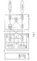
- FIG. 3which shows an example of MIMO data transmission.
- the figureillustrates a transmitter 300 , which may be a base station of the radio system, for example.
- the transmittercomprises two antennas 302 a , 302 b for transmitting a signal.
- the signal to be transmitted to the antennasarrives from transmitter units 304 a , 304 b .
- the receiver 306may be a terminal of the radio system, for example.
- the receivercomprises two antennas 308 a , 308 b for receiving the signal.
- the signal transmitted from the antennas 302 a , 302 b of the transmitter 300propagates at least along four different routes 314 a , 314 b , 316 a , 316 b to the antennas 308 a , 308 b of the receiver.
- the channel model of these routescan be marked with h 11 , h 12 , h 21 and h 22 .
- the receiverfurther comprises an equalizer 312 where the symbols received from different antennas are combined and decoded.
- the transceivers at both ends of the radio pathhave two antennas available. It should be remembered that this is only one example and the number of antennas can vary. As regards the invention, it is only necessary that one transceiver, preferably the one that transmits the signal, comprise two antennas.
- the base station equipmentcan be easily provided with an antenna array, but it is easier to implement a terminal using one antenna, or at most two.
- a first transceivertypically transmits packets to a second transceiver. Convolution coding is performed first on the packet to be transmitted and the encoded bits are divided into three blocks, for example. At the beginning, the first transceiver transmits only the first block to the second transceiver. The first block includes the bits for finding out the content of the whole packet in decoding if the signal-to-noise ratio is good enough.
- the second transceiverchecks whether the block was received successfully, and transmits a positive (ACK) or a negative (NACK) acknowledgement to the transmitter.
- ACKpositive
- NACKnegative
- the packetcan be supplied to further processing.
- the first transceiverAfter unsuccessful reception the block the reception of which failed is temporarily stored in memory. Having received a negative acknowledgement the first transceiver transmits the second block of the packet. In that case the second transceiver combines both the packets together. This provides coding stronger than that of the first block for decoding. If decoding still fails, the first transceiver is requested to transmit the next block.
- the information packet to be transmittedis encoded in the first transceiver and divided into different blocks in step 400 , as explained above.
- the block to be transmittedis divided into separate bursts.
- the number of burstsis divisible by the number of antennas used in transmission, let the number be n T .
- the burstsare divided into n T groups which are multiplied by the matrices A 1 and B 1 according to formula (1) in step 406 .
- Each groupis transmitted from an antenna of its own in step 408 .
- step 410the second transceiver receives the bursts and checks in step 412 whether the reception succeeded. If it did, the second transceiver transmits a positive acknowledgement to the first transceiver in step 414 .
- the second transceiverstores the bursts temporarily in memory in step 416 and transmits a negative acknowledgement to the first transceiver in step 418 .
- the same nT burstsare multiplied by the matrices A 1 and B 1 according to formula (1).
- the groupsare transmitted in step 422 .
- step 424the second transceiver receives the bursts and in step 426 reads the stored bursts from memory and performs space-time block decoding.
- step 428the second transceiver checks whether the reception succeeded. If it did, the second transceiver transmits a positive acknowledgement to the first transceiver in step 430 .
- the second transceivertransmits a negative acknowledgement to the first transceiver in step 432 .
- the same burstsare transmitted again according to step 404 .
- step 406 and step 420are carried out in step 406 and the blocks multiplied for retransmission are kept in memory till step 420 , if any.
- the space-time block coding employed in the preferred embodiments of the inventiondiffers from original space-time block coding in that the transmission channel may have changed between the transmission and the retransmission.
- the matrices H 1 and H 2 of formula (1)are replaced with four matrices H 11 , H 12 , H 21 , H 22 .
- Formula (1)will read as follows:
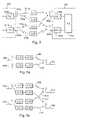
- FIG. 5 aillustrates an example of formula (3).
- the example illustrated in the figurecomprises two transmitting antennas 500 , 502 and one receiving antenna 504 . Between the antennas there are two transmission paths 508 and 510 .
- a first groupis transmitted first on the transmission path 508 from the antenna 500 to the antenna 504 , the channel being defined by channel coefficient H 11 .
- a second groupis transmitted from the antenna 502 along the path 510 , the transmission channel being defined by channel coefficient H 21 . If retransmission occurs, the first group is retransmitted from the antenna 500 multiplied by different matrices, the channel being defined by channel coefficient H 12 .
- the second groupis retransmitted from the antenna 502 multiplied by different matrices along the path 510 , the transmission channel being defined by channel coefficient H 22 .
- FIG. 5 bAn example of formula (4) is illustrated in FIG. 5 b .
- the example shown in the figurecomprises two transmitting antennas 500 , 502 and two receiving antennas 504 , 508 . Between the antennas there are four transmission paths 508 to 514 .
- a first groupis transmitted first from the antenna 500 .
- the antenna 504receives the group from the transmission path 508 , the channel being defined by channel coefficient H 11 .
- the antenna 506simultaneously receives the group on the transmission path 512 , the ch transmitted from the antenna 502 .
- the antenna 506receives the group along the path 510 , the transmission channel being defined by channel coefficient H 21 .
- the antenna 504simultaneously receives the same group along the path 514 , the transmission channel being defined by channel coefficient H 41 .
- the first groupis retransmitted multiplied by different matrices from the antenna 500 .
- the antenna 504receives the group from the transmission path 508 , the channels being defined by channel coefficient H 12 .
- the antenna 506simultaneously received the group on the transmission path 512 , the channel being defined by channel coefficient H 32 .
- the second group multiplied by different matricesis re-transmitted from the antenna 502 .
- the antenna 506receives the group along the path 510 , the transmission channel being defined by channel coefficient H 22 .
- the antenna 504simultaneously receives the same group along the path 514 , the transmission channel being defined by channel coefficient H 42 .
- the preferred embodiments of the inventioncan thus be applied regardless of whether there are one or more receiving antennas. If the number of antennas is two, the MIMO transmission enables a high transmission rate when the signal-to-noise ratio is good. On the other hand, if the signal-to-noise ratio is poor, the coding used in retransmission enables transmission which is immune to noise.
- the matrices A and B presented in the above-mentioned formulae (1, 3 and 4)can be selected so that they fulfil the conditions of formula (2).
- the selectioncan be made according to the known principles of space-time block coding, which are described in greater detail e.g. in Tarokh, V. et al cited above, and it is therefore unnecessary to explain the selection more closely in this context.
- the space-time block code employed in the preferred embodiments of the inventiondiffers from the original space-time block code in that the transmission channel may have changed between transmission and retransmission.
- the matrices A and B, particularly when frequency hopping is in usedo not necessarily need to fulfil all the conditions given in formula (2) to provide a functioning system.
- the channelscorrelate strongly, proper STBC coding provides a good result.
- space-time block codingwhere two transmitting antennas are used. Assume that the symbols to be transmitted are grouped into blocks s 1 and s 2 containing two symbols. In this embodiment the same blocks are retransmitted, if necessary, from the first transceiver in a pre-determined format to obtain space-time block coding.
- the codingis determined by a 2 ⁇ 2 matrix:
- the symbolsare first transmitted as such, i.e. s 1 and s 2 from antennas of their own. If reception succeeds, the next symbols will be transmitted. If reception fails, retransmission will be carried out. Now the same symbols are transmitted as ⁇ s 2 * and s 1 * in accordance with the 2 ⁇ 2 matrix.
- Space-time block codingcan be performed in the receiver because a space-time block coded symbol group is obtained by combining the symbols transmitted first with the retransmitted symbols.
- the blocks of the original transmissionare re-transmitted but in a different format, which has been selected to allow utilization of the properties of the space-time block code in reception.
- This formatis obtained by matrix multiplication, by multiplication by coefficients, or by another suitable calculation or conversion.
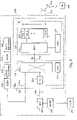
- the figureshows the parts of the first transceiver 600 and the second transceiver that are relevant to the invention.
- the transceiversalso comprise other components, which is obvious to a person skilled in the art, but they are not described here.
- the first transceivercomprises a space-time block encoder 604 , whose input includes the signal 608 to be transmitted.
- the ST encoderthe signal is coded and divided into different blocks, which are further divided into separate bursts, the number of which is divisible by the number of antennas used in transmission. In the transceiver used as the example this number is 2.
- the burstsare divided into two groups, which are multiplied by the matrices A 1 and B 1 .
- the multiplied burstsare supplied to radio frequency parts 610 , where they are amplified, converted into the radio frequency and transmitted via antennas 612 and 614 .
- a control block 616controls the operation of the different parts of the first transceiver.
- the ST encoder 604like the control block, can be implemented by a processor and suitable software, by separate components or by a combination of a processor and components and suitable software.
- the radio frequency parts 610can be implemented according to the prior art.
- the first transceiverfurther comprises receiving parts 618 and a receiving antenna 620 .
- receiving parts 618 and a receiving antenna 620are used as the transmitting antennas and as the receiving antennas in a receiver.
- the second transceiver 602includes two receiving antennas 622 , 624 for receiving the transmitted bursts and corresponding radio frequency parts 626 , 628 to which the bursts received by the antennas are supplied and in which the bursts are converted into an intermediate frequency or into the baseband.
- the received signalis supplied to pre-filters 630 , where the signals transmitted by different antennas are separated from one another.
- pre-filters 630This can be done in several ways known to a person skilled in the art.
- One wayis to use an interference suppression method where a desired signal is received and the other signals are treated as interfence.
- the purpose of the pre-filtersis to eliminate interference and shorten the impulse response of the desired signal.
- equalizers 632 , 634From the intermediate filters the signals are supplied to equalizers 632 , 634 , where the signal is further equalized e.g. by a delayed decision feedback sequence estimator DDFSE and by an MAP (maximum a posteriori probability) estimator connected in series with the DDFSE. Equalization and pre-filtering can be based e.g. on minimum mean-square error decision feedback equalization DFE. From the equalizer the signal is supplied to channel decoders 636 , 638 .
- DDFSEdelayed decision feedback sequence estimator
- MAPmaximum a posteriori probability estimator
- a control block 640controls the operation of the different parts of the second transceiver.
- the equalizers 632 , 634can be implemented by a processor and suitable software, by separate components, or by a combination of a processor and components and suitable software.
- the radio frequency parts 626 , 628 and the channel decoders 636 , 638can be implemented according to the prior art.
- the second transceiverfurther comprises transmitting parts 642 and a receiving antenna 644 .
- transmitting parts 642and a receiving antenna 644 .
- the same antennasare used as the transmitting antennas and as the receiving antennas in a receiver.
- the channel decoderstry to decode the received bursts, and if they do not succeed in this, a negative acknowledgement is transmitted to the first transceiver by the transmitting means 642 and the transmitting antenna 644 .
- the bursts the reception of which failedare stored temporarily in memory 646 .
- the first transceiverreceives the acknowledgement by the antenna 620 and receiving parts 618 , and the control means 616 control the ST encoder to make it multiply the same n T bursts by the matrices A 2 and B 2 and performs retransmission.
- the channel decoders 636 , 638receive the retransmitted and the received bursts from the equalizers and the bursts received earlier from memory 646 . These bursts are space-time block coded in the channel decoder by methods known to a person skilled in the art.
Landscapes
- Engineering & Computer Science (AREA)
- Computer Networks & Wireless Communication (AREA)
- Signal Processing (AREA)
- Mobile Radio Communication Systems (AREA)
- Detection And Prevention Of Errors In Transmission (AREA)
- Radio Transmission System (AREA)
Abstract
Description
z=(H1H2)*y
and the signals from several antennas are combined. Here H1and H2represent the transmission channel. It can be noted here that if the matrices Aiand Biare unit matrices, transmission occurs via two antennas without coding. If there are zeros on the main diagonal of the matrices Aiand Biand ones on some other diagonals, we obtain the delay diversity.
AiAk*=−AkAj*ja BiBk=−BkBj
AiAi*=I ja BiBi*=I (2)
AiBk=BkAi
where i, j and k represent possible different indices.
Claims (12)
Priority Applications (2)
| Application Number | Priority Date | Filing Date | Title |
|---|---|---|---|
| US09/893,735US7031419B2 (en) | 2001-06-29 | 2001-06-29 | Data transmission method and system |
| EP02396067AEP1271835A3 (en) | 2001-06-29 | 2002-05-10 | Data transmission method and system |
Applications Claiming Priority (1)
| Application Number | Priority Date | Filing Date | Title |
|---|---|---|---|
| US09/893,735US7031419B2 (en) | 2001-06-29 | 2001-06-29 | Data transmission method and system |
Publications (2)
| Publication Number | Publication Date |
|---|---|
| US20030012318A1 US20030012318A1 (en) | 2003-01-16 |
| US7031419B2true US7031419B2 (en) | 2006-04-18 |
Family
ID=25401992
Family Applications (1)
| Application Number | Title | Priority Date | Filing Date |
|---|---|---|---|
| US09/893,735Expired - LifetimeUS7031419B2 (en) | 2001-06-29 | 2001-06-29 | Data transmission method and system |
Country Status (2)
| Country | Link |
|---|---|
| US (1) | US7031419B2 (en) |
| EP (1) | EP1271835A3 (en) |
Cited By (25)
| Publication number | Priority date | Publication date | Assignee | Title |
|---|---|---|---|---|
| US20040062221A1 (en)* | 2002-09-30 | 2004-04-01 | Nandu Gopalakrishnan | Signaling and control mechanisms in MIMO harq schemes for wireless communication systems |
| US20040190639A1 (en)* | 2001-08-10 | 2004-09-30 | Mathias Pauli | Channel estimation in a multi carrier transmit diversity system |
| US20050052991A1 (en)* | 2003-09-09 | 2005-03-10 | Tamer Kadous | Incremental redundancy transmission in a MIMO communication system |
| US20050124297A1 (en)* | 2003-12-05 | 2005-06-09 | Eilts Henry S. | Low overhead transmit channel estimation |
| US20060171353A1 (en)* | 2003-06-18 | 2006-08-03 | Nippon Telegraph And Telephone Corporation | Radio packet communication method |
| US20060270427A1 (en)* | 2005-05-30 | 2006-11-30 | Masaaki Shida | Wireless transceiver |
| US20070092020A1 (en)* | 2005-10-24 | 2007-04-26 | Fujitsu Limited | Radio communication method and system, and receiver apparatus and transmitter apparatus |
| US20080025429A1 (en)* | 2006-07-25 | 2008-01-31 | Marvell International Ltd. | Concatenation-assisted symbol-level combining for MIMO systems with HARQ and/or repetition coding |
| US20080198941A1 (en)* | 2006-08-18 | 2008-08-21 | Leilei Song | Low-complexity scalable architecture for concatenation-assisted symbol-level combining |
| US20090042519A1 (en)* | 2005-01-25 | 2009-02-12 | Matsushita Electric Industrial Co., Ltd. | Transmission device and transmission method |
| US20090179772A1 (en)* | 2008-01-11 | 2009-07-16 | Mitsubishi Electric Corporation | In-vehicle apparatus remote control system and in-vehicle apparatus remote control method |
| US20090249097A1 (en)* | 2008-03-31 | 2009-10-01 | Lam Son H | Optimizing performance and power consumption during memory power down state |
| US20100014601A1 (en)* | 2006-06-23 | 2010-01-21 | Panasonic Corporation | Retransmission of data in a multiple input multiple output (mimo) system |
| US20100058137A1 (en)* | 2007-05-21 | 2010-03-04 | Fujitsu Limited | Data retransmission method and radio communication system using the same |
| US20110194487A1 (en)* | 2010-02-08 | 2011-08-11 | Qualcomm Incorporated | Enhanced resequencing of data received over a wireless communication system |
| US8411778B1 (en) | 2006-08-08 | 2013-04-02 | Marvell World Trade Ltd. | Optimal linear equalizer for MIMO systems with HARQ and/or repetition coding |
| US8498195B1 (en) | 2007-03-30 | 2013-07-30 | Marvell International Ltd. | HARQ retransmission scheme for at least two transmit antennas |
| US8619910B1 (en) | 2007-04-11 | 2013-12-31 | Marvell International Ltd. | Decision feedback equalization for MIMO systems with hybrid ARQ |
| US8699601B1 (en) | 2006-08-08 | 2014-04-15 | Marvell World Trade Ltd. | Distance-level combining for MIMO systems with HARQ and/or repetition coding |
| US8718166B2 (en) | 2006-08-08 | 2014-05-06 | Marvell World Trade Ltd. | Maximal ratio combining of equalized symbols for MIMO systems with HARQ and/or repetition coding |
| US8929472B1 (en) | 2006-07-26 | 2015-01-06 | Marvell International Ltd. | Bit-level combining for MIMO systems with HARQ and/or repetition coding |
| US20150155976A1 (en)* | 2012-08-02 | 2015-06-04 | Huawei Technologies Co., Ltd. | Data Retransmission Method, Apparatus, and System |
| US9551785B1 (en) | 1999-04-07 | 2017-01-24 | James L. Geer | Method and apparatus for the detection of objects using electromagnetic wave attenuation patterns |
| US10796056B2 (en) | 2018-06-21 | 2020-10-06 | Globalfoundries Inc. | Optimizing library cells with wiring in metallization layers |
| US11819690B2 (en) | 2007-05-31 | 2023-11-21 | Cochlear Limited | Acoustic output device with antenna |
Families Citing this family (37)
| Publication number | Priority date | Publication date | Assignee | Title |
|---|---|---|---|---|
| US20020110108A1 (en)* | 2000-12-07 | 2002-08-15 | Younglok Kim | Simple block space time transmit diversity using multiple spreading codes |
| US7447967B2 (en)* | 2001-09-13 | 2008-11-04 | Texas Instruments Incorporated | MIMO hybrid-ARQ using basis hopping |
| US20030066004A1 (en)* | 2001-09-28 | 2003-04-03 | Rudrapatna Ashok N. | Harq techniques for multiple antenna systems |
| SE0103853D0 (en)* | 2001-11-15 | 2001-11-15 | Ericsson Telefon Ab L M | Method and system of retransmission |
| JP3913575B2 (en)* | 2002-02-28 | 2007-05-09 | 三洋電機株式会社 | Wireless device, wireless communication system, space path control method, and space path control program |
| FI20021013A0 (en)* | 2002-05-29 | 2002-05-29 | Nokia Corp | Procedure for data communication and data transmission systems |
| US7006804B1 (en)* | 2002-07-10 | 2006-02-28 | At&T Corp. | High-speed two-way point-to-point transmission |
| EP2259478A1 (en)* | 2002-10-18 | 2010-12-08 | Panasonic Corporation | Constellation rearrangement for ARQ transmit diversity schemes |
| US7688902B1 (en) | 2003-04-16 | 2010-03-30 | Marvell International Ltd. | Joint space-time block decoding and viterbi decoding |
| KR100575929B1 (en) | 2003-05-29 | 2006-05-02 | 삼성전자주식회사 | Apparatus and method for transmitting and receiving data using multi-antenna diversity scheme in mobile communication system |
| EP1635516B1 (en)* | 2003-06-18 | 2015-11-18 | Nippon Telegraph And Telephone Corporation | Radio packet communication method |
| GB0316692D0 (en)* | 2003-07-17 | 2003-08-20 | Koninkl Philips Electronics Nv | Enhanced multi-path for mimo devices |
| US7668125B2 (en)* | 2003-09-09 | 2010-02-23 | Qualcomm Incorporated | Incremental redundancy transmission for multiple parallel channels in a MIMO communication system |
| US7437135B2 (en) | 2003-10-30 | 2008-10-14 | Interdigital Technology Corporation | Joint channel equalizer interference canceller advanced receiver |
| US7400692B2 (en) | 2004-01-14 | 2008-07-15 | Interdigital Technology Corporation | Telescoping window based equalization |
| US7940663B2 (en) | 2004-07-20 | 2011-05-10 | Qualcomm Incorporated | Mitigating ACK/NACK errors in MIMO/SIC/HARQ |
| KR100714973B1 (en) | 2004-08-16 | 2007-05-04 | 삼성전자주식회사 | Apparatus and method for changing signal point mapping rules in hybrid automatic retransmission request system |
| KR100913873B1 (en)* | 2004-09-13 | 2009-08-26 | 삼성전자주식회사 | Apparatus and method for differential space-time block coder with high data rate |
| US20060092877A1 (en)* | 2004-10-21 | 2006-05-04 | Nokia Corporation | Data transport in GSM system |
| EP1805925A4 (en)* | 2004-10-25 | 2011-06-22 | Lg Electronics Inc | A method of selecting retransmission format in a wireless communication multiple antenna system |
| AU2005319950B2 (en)* | 2004-12-23 | 2010-07-01 | Electronics And Telecommunications Research Institute | Apparatus for transmitting and receiving data to provide high-speed data comunication and method thereof |
| JP4824016B2 (en)* | 2005-03-15 | 2011-11-24 | 富士通株式会社 | Communication apparatus and communication method |
| US7486727B2 (en)* | 2005-04-15 | 2009-02-03 | Agere Systems Inc. | Reconfigurable communications circuit |
| US8229008B2 (en) | 2005-07-26 | 2012-07-24 | Nvidia Corporation | Interference mitigation for orthogonal frequency division multiplexing communication |
| KR101245403B1 (en) | 2005-08-12 | 2013-03-25 | 뉴저지 인스티튜트 오브 테크놀로지 | RETRANSMISSION ORDERING METHOD AND APPARATUS USING AN NxM ANTENNAS MIMO SYSTEM |
| JP4955972B2 (en) | 2005-09-27 | 2012-06-20 | キヤノン株式会社 | Data communication apparatus, control method therefor, and program |
| KR100842521B1 (en)* | 2005-11-22 | 2008-07-01 | 삼성전자주식회사 | Apparatus and method for transmitting/receiving a signal in a communication system |
| AU2007240912B2 (en)* | 2006-04-18 | 2010-05-20 | Interdigital Technology Corporation | Method and apparatus for implementing H-ARQ in a mimo wireless communication system |
| US8090063B2 (en)* | 2006-07-26 | 2012-01-03 | Marvell World Trade Ltd. | Symbol-level combining for multiple input multiple output (MIMO) systems with hybrid automatic repeat request (HARQ) and/or repetition coding |
| US8027402B2 (en)* | 2006-07-26 | 2011-09-27 | Marvell World Trade Ltd. | Symbol-level combining for multiple input multiple output (MIMO) systems with hybrid automatic repeat request (HARQ) and/or repetition coding |
| US8014470B2 (en)* | 2006-09-13 | 2011-09-06 | Marvell World Trade Ltd. | Decoding method for Alamouti scheme with HARQ and/or repetition coding |
| US8799742B1 (en) | 2007-07-30 | 2014-08-05 | Marvell International Ltd. | QC-LDPC decoder with list-syndrome decoding |
| US8127209B1 (en) | 2007-07-30 | 2012-02-28 | Marvell International Ltd. | QC-LDPC decoder with list-syndrome decoding |
| US8176378B2 (en)* | 2007-09-07 | 2012-05-08 | Broadcom Corporation | Method and system for a transmitting antenna selection failure recovery mode |
| ES2363953B1 (en)* | 2009-07-27 | 2012-07-03 | Vodafone España, S.A.U. | SYSTEM AND METHOD FOR DATA TRANSMISSION IN A LARGE AREA MOBILE NETWORK. |
| KR101063623B1 (en) | 2010-09-17 | 2011-09-07 | 중앙대학교 산학협력단 | Method and apparatus for transmitting and receiving using multi-antenna multi-hybrid automatic repeat request based on space-time block code |
| CN113133130B (en)* | 2019-12-30 | 2022-05-20 | 成都鼎桥通信技术有限公司 | Communication method and device |
Citations (8)
| Publication number | Priority date | Publication date | Assignee | Title |
|---|---|---|---|---|
| EP0736979A2 (en) | 1995-04-03 | 1996-10-09 | AT&T IPM Corp. | Fast fading packet diversity transmission method and system |
| US5657325A (en) | 1995-03-31 | 1997-08-12 | Lucent Technologies Inc. | Transmitter and method for transmitting information packets with incremental redundancy |
| WO1999014871A1 (en) | 1997-09-16 | 1999-03-25 | At & T Wireless Services, Inc. | Transmitter diversity technique for wireless communications |
| US20020012337A1 (en)* | 2000-06-09 | 2002-01-31 | Schmidl Timothy M. | Wireless communications with efficient retransmission operation |
| US20020141414A1 (en)* | 1997-06-17 | 2002-10-03 | Ramin Rezaiifar | Method and apparatus for resolving ambiguity in reception of multiple retransmitted frames |
| US20030026348A1 (en)* | 2001-06-07 | 2003-02-06 | National University Of Singapore | Wireless communication apparatus and method |
| US6567388B1 (en)* | 1999-03-05 | 2003-05-20 | Qualcomm, Incorporated | Method and apparatus for efficient data retransmission in a voice-over-data communication system |
| US6728307B1 (en)* | 1999-09-13 | 2004-04-27 | Nokia Mobile Phones Ltd | Adaptive antenna transmit array with reduced CDMA pilot channel set |
- 2001
- 2001-06-29USUS09/893,735patent/US7031419B2/ennot_activeExpired - Lifetime
- 2002
- 2002-05-10EPEP02396067Apatent/EP1271835A3/ennot_activeWithdrawn
Patent Citations (8)
| Publication number | Priority date | Publication date | Assignee | Title |
|---|---|---|---|---|
| US5657325A (en) | 1995-03-31 | 1997-08-12 | Lucent Technologies Inc. | Transmitter and method for transmitting information packets with incremental redundancy |
| EP0736979A2 (en) | 1995-04-03 | 1996-10-09 | AT&T IPM Corp. | Fast fading packet diversity transmission method and system |
| US20020141414A1 (en)* | 1997-06-17 | 2002-10-03 | Ramin Rezaiifar | Method and apparatus for resolving ambiguity in reception of multiple retransmitted frames |
| WO1999014871A1 (en) | 1997-09-16 | 1999-03-25 | At & T Wireless Services, Inc. | Transmitter diversity technique for wireless communications |
| US6567388B1 (en)* | 1999-03-05 | 2003-05-20 | Qualcomm, Incorporated | Method and apparatus for efficient data retransmission in a voice-over-data communication system |
| US6728307B1 (en)* | 1999-09-13 | 2004-04-27 | Nokia Mobile Phones Ltd | Adaptive antenna transmit array with reduced CDMA pilot channel set |
| US20020012337A1 (en)* | 2000-06-09 | 2002-01-31 | Schmidl Timothy M. | Wireless communications with efficient retransmission operation |
| US20030026348A1 (en)* | 2001-06-07 | 2003-02-06 | National University Of Singapore | Wireless communication apparatus and method |
Non-Patent Citations (3)
| Title |
|---|
| Foschini, "Layered Space-Time Architecture for Wireless Communication in a Fading Environment When Using Multi-Element Antennas," Lucent Technologies, Inc., Bell Labs Technical Journal, Autumn 1996, pp. 41-59. |
| Sandhu et al., "Space-Time Block Codes: A Capacity Perspective," IEEE Communications Letters, vol. 4, No. 12, Dec. 2000, pp. 384-386. |
| Tarokh et al., "Space-Time Block Codes from Orthogonal Designs," IEEE Transactions on Information Theory, vol. 45, No. 5, Jul. 1999, pp. 1456-1467. |
Cited By (49)
| Publication number | Priority date | Publication date | Assignee | Title |
|---|---|---|---|---|
| US9551785B1 (en) | 1999-04-07 | 2017-01-24 | James L. Geer | Method and apparatus for the detection of objects using electromagnetic wave attenuation patterns |
| US7324600B2 (en)* | 2001-08-10 | 2008-01-29 | Telefonaktiebolaget Lm Ericsson (Publ) | Channel estimation in a multi carrier transmit diversity system |
| US20040190639A1 (en)* | 2001-08-10 | 2004-09-30 | Mathias Pauli | Channel estimation in a multi carrier transmit diversity system |
| US20040062221A1 (en)* | 2002-09-30 | 2004-04-01 | Nandu Gopalakrishnan | Signaling and control mechanisms in MIMO harq schemes for wireless communication systems |
| US7391755B2 (en)* | 2002-09-30 | 2008-06-24 | Lucent Technologies Inc. | Signaling and control mechanisms in MIMO harq schemes for wireless communication systems |
| US7974243B2 (en)* | 2003-06-18 | 2011-07-05 | Nippon Telegraph And Telephone Corporation | Wireless packet communication method and wireless packet communication apparatus |
| US20060171353A1 (en)* | 2003-06-18 | 2006-08-03 | Nippon Telegraph And Telephone Corporation | Radio packet communication method |
| US8989108B2 (en) | 2003-06-18 | 2015-03-24 | Nippon Telegraph And Telephone Corporation | Wireless packet communication method and wireless packet communication apparatus |
| US8908496B2 (en)* | 2003-09-09 | 2014-12-09 | Qualcomm Incorporated | Incremental redundancy transmission in a MIMO communication system |
| US20050052991A1 (en)* | 2003-09-09 | 2005-03-10 | Tamer Kadous | Incremental redundancy transmission in a MIMO communication system |
| US7231184B2 (en)* | 2003-12-05 | 2007-06-12 | Texas Instruments Incorporated | Low overhead transmit channel estimation |
| US20050124297A1 (en)* | 2003-12-05 | 2005-06-09 | Eilts Henry S. | Low overhead transmit channel estimation |
| US20090042519A1 (en)* | 2005-01-25 | 2009-02-12 | Matsushita Electric Industrial Co., Ltd. | Transmission device and transmission method |
| US7826871B2 (en)* | 2005-01-25 | 2010-11-02 | Panasonic Corporation | Transmission apparatus and transmission method |
| US20060270427A1 (en)* | 2005-05-30 | 2006-11-30 | Masaaki Shida | Wireless transceiver |
| US7493092B2 (en)* | 2005-05-30 | 2009-02-17 | Hitachi, Ltd. | Wireless transceiver having plural transmission methods |
| US20090147838A1 (en)* | 2005-05-30 | 2009-06-11 | Masaaki Shida | Wireless Transceiver |
| US8111667B2 (en) | 2005-05-30 | 2012-02-07 | Hitachi, Ltd. | Wireless transceiver |
| US20070092020A1 (en)* | 2005-10-24 | 2007-04-26 | Fujitsu Limited | Radio communication method and system, and receiver apparatus and transmitter apparatus |
| US8300722B2 (en)* | 2006-06-23 | 2012-10-30 | Panasonic Corporation | Retransmission of data in a multiple input multiple output (MIMO) system |
| US20100014601A1 (en)* | 2006-06-23 | 2010-01-21 | Panasonic Corporation | Retransmission of data in a multiple input multiple output (mimo) system |
| US8121209B2 (en) | 2006-07-25 | 2012-02-21 | Marvell World Trade Ltd. | Concatenation-assisted symbol-level combining for MIMO systems with HARQ and/or repetition coding |
| US20080025429A1 (en)* | 2006-07-25 | 2008-01-31 | Marvell International Ltd. | Concatenation-assisted symbol-level combining for MIMO systems with HARQ and/or repetition coding |
| US8320509B2 (en) | 2006-07-25 | 2012-11-27 | Marvell World Trade Ltd. | Concatenation-assisted symbol-level combining for MIMO systems with HARQ and/or repetition coding |
| US8670507B2 (en) | 2006-07-25 | 2014-03-11 | Marvell World Trade Ltd. | Concatentation-assisted symbol-level combining for MIMO systems with HARQ and/or repetition coding |
| US9240867B1 (en) | 2006-07-26 | 2016-01-19 | Marvell International Ltd. | Bit-level combining for MIMO systems with HARQ and/or repetition coding |
| US8929472B1 (en) | 2006-07-26 | 2015-01-06 | Marvell International Ltd. | Bit-level combining for MIMO systems with HARQ and/or repetition coding |
| US8699601B1 (en) | 2006-08-08 | 2014-04-15 | Marvell World Trade Ltd. | Distance-level combining for MIMO systems with HARQ and/or repetition coding |
| US9020062B2 (en) | 2006-08-08 | 2015-04-28 | Marvell World Trade Ltd. | Maximal ratio combining of equalized symbols for MIMO systems with HARQ and/or repetition coding |
| US8787486B2 (en) | 2006-08-08 | 2014-07-22 | Marvell World Trade Ltd. | Distance-level combining for MIMO systems with HARQ and/or repetition coding |
| US8411778B1 (en) | 2006-08-08 | 2013-04-02 | Marvell World Trade Ltd. | Optimal linear equalizer for MIMO systems with HARQ and/or repetition coding |
| US8718166B2 (en) | 2006-08-08 | 2014-05-06 | Marvell World Trade Ltd. | Maximal ratio combining of equalized symbols for MIMO systems with HARQ and/or repetition coding |
| US8718177B2 (en) | 2006-08-08 | 2014-05-06 | Marvell World Trade Ltd. | Optimal linear equalizer for MIMO systems with HARQ and/or repetition coding |
| US20080198941A1 (en)* | 2006-08-18 | 2008-08-21 | Leilei Song | Low-complexity scalable architecture for concatenation-assisted symbol-level combining |
| US8019023B2 (en)* | 2006-08-18 | 2011-09-13 | Marvell World Trade Ltd. | Low-complexity scalable architecture for concatenation-assisted symbol-level combining |
| US8498195B1 (en) | 2007-03-30 | 2013-07-30 | Marvell International Ltd. | HARQ retransmission scheme for at least two transmit antennas |
| US8619910B1 (en) | 2007-04-11 | 2013-12-31 | Marvell International Ltd. | Decision feedback equalization for MIMO systems with hybrid ARQ |
| US8341483B2 (en)* | 2007-05-21 | 2012-12-25 | Fujitsu Limited | Data retransmission method and radio communication system using the same |
| US20100058137A1 (en)* | 2007-05-21 | 2010-03-04 | Fujitsu Limited | Data retransmission method and radio communication system using the same |
| US11819690B2 (en) | 2007-05-31 | 2023-11-21 | Cochlear Limited | Acoustic output device with antenna |
| US12011593B2 (en) | 2007-05-31 | 2024-06-18 | Cochlear Limited | Acoustic output device with antenna |
| US20090179772A1 (en)* | 2008-01-11 | 2009-07-16 | Mitsubishi Electric Corporation | In-vehicle apparatus remote control system and in-vehicle apparatus remote control method |
| US8164417B2 (en)* | 2008-01-11 | 2012-04-24 | Mitsubishi Electric Corporation | In-vehicle apparatus remote control system and in-vehicle apparatus remote control method |
| US20090249097A1 (en)* | 2008-03-31 | 2009-10-01 | Lam Son H | Optimizing performance and power consumption during memory power down state |
| US8774190B2 (en)* | 2010-02-08 | 2014-07-08 | Qualcomm Incorporated | Enhanced resequencing of data received over a wireless communication system |
| US20110194487A1 (en)* | 2010-02-08 | 2011-08-11 | Qualcomm Incorporated | Enhanced resequencing of data received over a wireless communication system |
| US20150155976A1 (en)* | 2012-08-02 | 2015-06-04 | Huawei Technologies Co., Ltd. | Data Retransmission Method, Apparatus, and System |
| US9331821B2 (en)* | 2012-08-02 | 2016-05-03 | Huawei Technologies Co., Ltd. | Data retransmission method, apparatus, and system |
| US10796056B2 (en) | 2018-06-21 | 2020-10-06 | Globalfoundries Inc. | Optimizing library cells with wiring in metallization layers |
Also Published As
| Publication number | Publication date |
|---|---|
| EP1271835A3 (en) | 2005-09-07 |
| US20030012318A1 (en) | 2003-01-16 |
| EP1271835A2 (en) | 2003-01-02 |
Similar Documents
| Publication | Publication Date | Title |
|---|---|---|
| US7031419B2 (en) | Data transmission method and system | |
| JP4533742B2 (en) | Data transmission method and system | |
| US9736832B2 (en) | Wireless communications system that supports multiple modes of operation | |
| US8286047B2 (en) | Soft buffer memory configuration in a communication system | |
| US7809072B2 (en) | Transmitter and receiver for use in a relay network, and system and method for performing transmission and reception using the same | |
| CA2201316C (en) | Retransmission control method of cdma mobile communication | |
| CN1698302A (en) | Time diversity combining to increase the reliability of the IEEE 802.11WLAN receiver | |
| US20070190951A1 (en) | Data transmission method, transceiver and telecommunication system | |
| Zheng et al. | Multiple ARQ processes for MIMO systems | |
| WO2003034618A1 (en) | A METHOD AND SYSTEM TO INCREASE QoS AND RANGE IN A MULTICARRIER SYSTEM | |
| EP1405453B1 (en) | Transmission method and apparatus | |
| EP1126737B1 (en) | Apparatus, system and method for collision resolution in a delay-critical radio telecommunications system | |
| EP1842295A1 (en) | Data transfer in tdma system | |
| JP4223474B2 (en) | Data transmission method and system | |
| Hueda et al. | Enhanced-performance video transmission in multicode CDMA wireless systems using a feedback error control scheme | |
| US20020098824A1 (en) | Method for transmitting information in a communication system, a communication system and wireless communication device | |
| WO2003019849A1 (en) | Method of improving transmit diversity reliability by including interleaving the transmit data in a single time slot |
Legal Events
| Date | Code | Title | Description |
|---|---|---|---|
| AS | Assignment | Owner name:NOKIA CORPORATION, FINLAND Free format text:ASSIGNMENT OF ASSIGNORS INTEREST;ASSIGNOR:PIIRAINEN, OLLI;REEL/FRAME:012120/0752 Effective date:20010730 | |
| STCF | Information on status: patent grant | Free format text:PATENTED CASE | |
| AS | Assignment | Owner name:NOKIA SIEMENS NETWORKS OY, FINLAND Free format text:ASSIGNMENT OF ASSIGNORS INTEREST;ASSIGNOR:NOKIA CORPORATION;REEL/FRAME:020550/0001 Effective date:20070913 Owner name:NOKIA SIEMENS NETWORKS OY,FINLAND Free format text:ASSIGNMENT OF ASSIGNORS INTEREST;ASSIGNOR:NOKIA CORPORATION;REEL/FRAME:020550/0001 Effective date:20070913 | |
| FPAY | Fee payment | Year of fee payment:4 | |
| FEPP | Fee payment procedure | Free format text:PAYER NUMBER DE-ASSIGNED (ORIGINAL EVENT CODE: RMPN); ENTITY STATUS OF PATENT OWNER: LARGE ENTITY Free format text:PAYOR NUMBER ASSIGNED (ORIGINAL EVENT CODE: ASPN); ENTITY STATUS OF PATENT OWNER: LARGE ENTITY | |
| FPAY | Fee payment | Year of fee payment:8 | |
| AS | Assignment | Owner name:NOKIA SOLUTIONS AND NETWORKS OY, FINLAND Free format text:CHANGE OF NAME;ASSIGNOR:NOKIA SIEMENS NETWORKS OY;REEL/FRAME:034294/0603 Effective date:20130819 | |
| MAFP | Maintenance fee payment | Free format text:PAYMENT OF MAINTENANCE FEE, 12TH YEAR, LARGE ENTITY (ORIGINAL EVENT CODE: M1553) Year of fee payment:12 | |
| AS | Assignment | Owner name:NOKIA TECHNOLOGIES OY, FINLAND Free format text:ASSIGNMENT OF ASSIGNORS INTEREST;ASSIGNOR:NOKIA SOLUTIONS AND NETWORKS OY;REEL/FRAME:047271/0806 Effective date:20180702 |