US7031336B2 - Space-time-power scheduling for wireless networks - Google Patents
Space-time-power scheduling for wireless networksDownload PDFInfo
- Publication number
- US7031336B2 US7031336B2US10/306,972US30697202AUS7031336B2US 7031336 B2US7031336 B2US 7031336B2US 30697202 AUS30697202 AUS 30697202AUS 7031336 B2US7031336 B2US 7031336B2
- Authority
- US
- United States
- Prior art keywords
- station
- access point
- wireless network
- stations
- frames
- Prior art date
- Legal status (The legal status is an assumption and is not a legal conclusion. Google has not performed a legal analysis and makes no representation as to the accuracy of the status listed.)
- Expired - Lifetime, expires
Links
- 230000005540biological transmissionEffects0.000claimsabstractdescription105
- 238000000034methodMethods0.000claimsabstractdescription51
- 238000001514detection methodMethods0.000claimsdescription16
- 238000003491arrayMethods0.000claimsdescription3
- 239000011159matrix materialSubstances0.000description25
- 230000001965increasing effectEffects0.000description15
- 230000008569processEffects0.000description14
- 230000004044responseEffects0.000description14
- 238000005259measurementMethods0.000description12
- 230000002452interceptive effectEffects0.000description10
- 238000010586diagramMethods0.000description9
- 238000004891communicationMethods0.000description7
- 230000000875corresponding effectEffects0.000description6
- 230000003993interactionEffects0.000description6
- 230000006870functionEffects0.000description5
- 230000002829reductive effectEffects0.000description5
- 230000008901benefitEffects0.000description4
- 230000007704transitionEffects0.000description4
- 239000013598vectorSubstances0.000description4
- 101100172132Mus musculus Eif3a geneProteins0.000description3
- 230000003044adaptive effectEffects0.000description3
- 230000003247decreasing effectEffects0.000description3
- 238000013439planningMethods0.000description3
- 239000000523sampleSubstances0.000description3
- 238000012384transportation and deliveryMethods0.000description3
- 238000013459approachMethods0.000description2
- 230000008859changeEffects0.000description2
- 239000003795chemical substances by applicationSubstances0.000description2
- 230000002596correlated effectEffects0.000description2
- 238000005562fadingMethods0.000description2
- 230000001788irregularEffects0.000description2
- 230000007246mechanismEffects0.000description2
- 230000004048modificationEffects0.000description2
- 238000012986modificationMethods0.000description2
- 230000035945sensitivityEffects0.000description2
- 238000004088simulationMethods0.000description2
- 230000002776aggregationEffects0.000description1
- 238000004220aggregationMethods0.000description1
- 230000003466anti-cipated effectEffects0.000description1
- 230000001174ascending effectEffects0.000description1
- 230000004888barrier functionEffects0.000description1
- 230000033228biological regulationEffects0.000description1
- 238000012937correctionMethods0.000description1
- 238000005314correlation functionMethods0.000description1
- 230000001934delayEffects0.000description1
- 230000000694effectsEffects0.000description1
- 238000005286illuminationMethods0.000description1
- 230000001939inductive effectEffects0.000description1
- 230000000670limiting effectEffects0.000description1
- 238000007726management methodMethods0.000description1
- 230000036961partial effectEffects0.000description1
- 230000000737periodic effectEffects0.000description1
- 229920001690polydopaminePolymers0.000description1
- 238000012545processingMethods0.000description1
- 230000009467reductionEffects0.000description1
- 230000003068static effectEffects0.000description1
- 230000001629suppressionEffects0.000description1
- 238000012360testing methodMethods0.000description1
- 238000012546transferMethods0.000description1
Images


Classifications
- H—ELECTRICITY
- H04—ELECTRIC COMMUNICATION TECHNIQUE
- H04W—WIRELESS COMMUNICATION NETWORKS
- H04W28/00—Network traffic management; Network resource management
- H04W28/16—Central resource management; Negotiation of resources or communication parameters, e.g. negotiating bandwidth or QoS [Quality of Service]
- H04W28/18—Negotiating wireless communication parameters
- H—ELECTRICITY
- H04—ELECTRIC COMMUNICATION TECHNIQUE
- H04W—WIRELESS COMMUNICATION NETWORKS
- H04W52/00—Power management, e.g. Transmission Power Control [TPC] or power classes
- H04W52/04—Transmission power control [TPC]
- H04W52/18—TPC being performed according to specific parameters
- H04W52/24—TPC being performed according to specific parameters using SIR [Signal to Interference Ratio] or other wireless path parameters
- H—ELECTRICITY
- H04—ELECTRIC COMMUNICATION TECHNIQUE
- H04W—WIRELESS COMMUNICATION NETWORKS
- H04W72/00—Local resource management
- H04W72/50—Allocation or scheduling criteria for wireless resources
- H04W72/54—Allocation or scheduling criteria for wireless resources based on quality criteria
- H04W72/542—Allocation or scheduling criteria for wireless resources based on quality criteria using measured or perceived quality
- H—ELECTRICITY
- H04—ELECTRIC COMMUNICATION TECHNIQUE
- H04W—WIRELESS COMMUNICATION NETWORKS
- H04W88/00—Devices specially adapted for wireless communication networks, e.g. terminals, base stations or access point devices
- H04W88/12—Access point controller devices
Definitions
- the present inventionrelates to wireless networks, and more particularly, to space/time/power RF routing for such networks.
- IEEE 802.11is a wireless standard related to the IEEE 802.3 standard established for wired Ethernets. In contrast to wired networks, an IEEE 802.11 WLAN must conserve the limited bandwidth presented by a wireless transmission medium. Accordingly, a set of rules in the IEEE 802.11 standard is dedicated to medium access control (MAC), which governs accessing the wireless medium and sending data through it.
- MACmedium access control
- multiple wireless nodes or stationssuch as laptops may communicate through an access point (AP) with other users of a wired local area network (LAN).
- APaccess point
- LANwired local area network
- the MACspecifies a carrier sense multiple access/collision avoidance scheme (CSMA/CA) as controlled by a distribution coordination function (DCF).
- CSMA/CAcarrier sense multiple access/collision avoidance scheme
- DCFdistribution coordination function
- the DCFfirst checks that the radio link is clear before transmitting. If another transmission is detected, the DCF specifies a random backoff period (DCF inter-frame space or DIFS). Only if the channel is clear after the expiration of the random time period, may a STA begin transmission. Because two STAs may communicate with a given AP but be out of range with respect to each other, the DCF also specifies a virtual carrier sense (VCS) procedure by which the wireless medium is reserved for a specified period of time for an impending transmission. For example, the VCS may be implemented by the use of request-to send (RTS) and clear-to-send (CTS) frames. A given STA would signal the beginning of a transmission with an RTS which specifies a reservation period.
- VCSvirtual carrier sense
- the APresponds with a CTS that will be received by the remaining STAs.
- This CTSwill communicate the reservation period to all the STAs, which update their Network Allocation Vector (NAV) accordingly.
- NAVNetwork Allocation Vector
- the NAVacts as a timer for the reservation period and protects data transmissions by causing the medium to be non-idle over the duration of the entire frame exchange.
- DCF with CSMA/CAreduces the possibility of collision, it does not eliminate it due to “hidden stations” reality. Further, DCF is not suited for time-sensitive applications because of the unbounded delays in the presence of congestion or interference. DCF may also under-utilize available bandwidth due to access contention. This inefficiency is increased because of the excessive overhead and the low data rate at which the preamble and PLCP header are transmitted. When this is used with RTS/CTS (Request to Send/Clear to Send) control frames, e.g., to handle the “hidden” station problem, inefficiency is increased even further.
- RTS/CTSRequest to Send/Clear to Send
- PCFPoint Coordination Function
- PCFspecifies the use of special stations in APs denoted as point coordinators, which act to ensure contention-free (CF) service.
- PCFis a centrally based access control mechanism (as opposed to a distributed architecture) based on a polling and response protocol, where DCF is based on CSMA/CA.
- CCPcontention free period
- STASTA can only transmit after being polled by the Point Coordinator (PC).
- the PCmay send polling frames to STAs that have requested contention-free services for their uplink traffic. If a polled STA has uplink traffic to send, it may transmit one frame for each polling frame received.
- the PCexpects a response within a short inter-frame space (SIFS), which is shorter than a priority inter-frame space (PIFS).
- SIFSshort inter-frame space
- PCFPCF
- the CFP repetition rateis not dynamically variable, there is a trade-off between low latency applications requiring a fast repetition rate and an efficient use of the medium requiring slower repetition rate.
- the start of a CF periodis not exactly periodic (i.e., it can only begin when the medium is sensed to be idle).
- the CFPmay be forced to end before serving some STAs on the polling list.
- all the CF-pollable APshave the same level of priority since they are simply polled by ascending Association ID (AID), and the PC has to poll all the STAs on its polling list even if there is no traffic to be sent.
- AIDascending Association ID
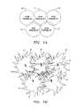
- DCFIn addition to governing medium access, DCF also specifies rules for the frequency scheme that may be implemented in a WLAN having multiple APs. For example, FIG. 1 a shows a WLAN having coverage areas or cells 10 corresponding to four APs. To minimize contention between adjacent APs, each AP is assigned a frequency channel for its cell 10 . FIG. 1 a shows that the overlap of cells 10 allows complete coverage within the WLAN.
- IEEE 802.11 WLANsuffers from the rigidity required by the DCF.
- FCC regulationslimit the amount of power that can be used by the APs and STAs.
- the DCF rigidity and power allocation limitspresent severe challenges to users during network deployment and modification. Even if careful network planning is implemented, there may still be loss of bandwidth due to unpredictable circumstances such as a subscriber's movement and activity level.
- the overall network bandwidthis limited by non-adjacent cell interference such that cells cannot be readily reduced in size to boost bandwidth.
- frequency channelsare used for interference-avoidance planning, cell bandwidth is limited to a single AP bandwidth. When external interference is present, system frequency cannot be easily changed since the frequency resource already been used for another purpose.
- FIG. 1 aillustrates an ideal situation where each cell 10 has a circular coverage area.
- the coverage area of each cell 10is not a circle.
- numerous APs and STAsare needed to allow STAs to transfer information between each other.
- the walls and other barriersresult in non-uniform coverage areas for each cell 10 .
- FIG. 1 bshows coverage areas or cells 20 in a practical WLAN environment.
- the coverage areasare no longer uniform circles, but are irregular having areas of broader coverage (the peaks) and areas of lower coverage (the nulls).
- long peaks 25may correspond to long hallways in the building.
- holes 30exist in the network, where communication is not possible. Holes 30 do not necessarily represent areas where no frames are able to be sent and received, but rather only a small percentage of dropped frames are all that may be tolerated due to TCP/IP behavior, thereby effectively ending communication ability within that area.
- a possible solution to “fill” holes 30may be to increase the density of the APs in the WLAN, i.e., move the APs closer to each other, which requires more APs for the same outer coverage area.
- increasing the density of the APswill result in increased interference between APs and STAs, while also increasing the cost of the system. Consequently, in order to reduce interference, the transmit power of the APs must be reduced. But, this may again result in holes in the WLAN coverage due to irregular coverage “footprints” of the APs at an additional cost of a reduction in maximum throughput of the system.
- a wireless local area networkincludes a plurality of M access point (AP) transceivers, wherein each access point transceiver controls its own multi-element antenna.
- the networkincludes a plurality of N stations (STAs), wherein each station can communicate with all or a subset of the M access point transceivers.
- STAsN stations
- RFradio frequency
- a central controller or radio frequency (RF) routeris coupled to the plurality of M access points and is configured to examine the “transmission characteristics” between a subset of the stations and a subset of the antennas for each access point. Transmission characteristics include path losses between transmitter and receiver, transmission power, receive signal level, ratio between one transmission path loss and another, and other types of suitable information metrics.
- the controllerBased upon these transmission characteristics, the controller identifies frames that may be scheduled for simultaneous transmission from a subset of the access points to a subset of the stations, such that a given access point in the subset is uniquely assigned a given frame for simultaneous transmission to its intended station with high probability of delivery.
- transmission characteristicsinclude the relative path loss between APs to STAs and between APs to APs and the probability of interference from STA to another STA (estimated from the relative path loss).
- the relative path loss characteristicsare also known collectively as a spatial signature.
- the transmission characteristicsare based on signals at the receiving STA and/or AP.
- the controllerwhen it has the transmission characteristics of the APs and STAs within the network, it can select the best AP with which to transmit the frame to the appropriate STA. Selection metric is based on best signal delivery path and minimum interference to co-existing transmissions. If frame transmission, regardless of the AP selected, would interfere with an existing transmission, the controller may decide to hold the frame a fixed period of time until conditions change or drop the frame entirely.
- a plurality of such networkscan be utilized to create a larger system, with each network operating on its own unique frequency channel.
- system performancecan be significantly improved. For example, the probability of having an outage is greatly reduced, the range can be extended (from having the ability to select one of many APs instead of relying on just one AP), bandwidth is increased, interference is reduced, and system cost is lowered.
- the present inventionexploits the natural large path-loss variability within indoor environments. This variability, for example, is a result of extensive shadowing caused by walls and other objects and signal propagation through hallways and air ducts. In addition, extensive signal multipath propagation cause Rayleigh fading that further contributes to signal level variations.
- FIG. 1 aillustrates cells with theoretical footprints for a conventional WLAN.
- FIG. 1 billustrates an example of cells with realistic footprints in an enterprise.
- FIG. 2is a block diagram of a WLAN according to one embodiment of the invention.
- FIG. 3is an illustration of a channel gain matrix according to one embodiment of the invention.
- FIG. 4is an illustration of the coverage areas for three access points indicating regions of relatively low station-to-station spatial signature correlation and regions of relatively high station-to-station spatial signature correlation.
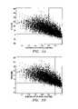
- FIG. 5 ais a graph of the cross-correlation vs. channel-to-interference ratio (C/I) for a plurality of stations to demonstrate the subset of stations that may be serviced simultaneously according to a cross-correlation threshold of 0.9.
- C/Ichannel-to-interference ratio
- FIG. 5 bis a graph of the cross-correlation vs. C/I for a plurality of stations to demonstrate the subset of stations that may be serviced simultaneously according to a cross-correlation threshold of 0.95.
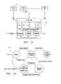
- FIG. 6is an illustration of a plurality of networks according to one embodiment of the invention.
- FIG. 7is a block diagram for an access point module according to one embodiment of the invention.
- FIG. 8is an antenna gain plot for the antenna array used in the access point module of FIG. 7 .
- FIG. 9is a block diagram for an access point module in which the medium access control (MAC) functions are implemented by the central controller according to one embodiment of the invention.
- MACmedium access control
- FIG. 10is block diagram for a central controller for the access point module of FIG. 7 .
- FIG. 11is a block diagram for a central controller for the access point module of FIG. 9 .
- FIG. 12is a state machine diagram for a probing process according to one embodiment of the invention.
- FIG. 2shows a block diagram of an exemplary IEEE 802.11 WLAN 15 configured to implement the space-time-power (STP) frame scheduling technique of the present invention.
- a central controller 20controls the medium access by a plurality of M access points (APs) (for illustration clarity, only two APs 25 and 30 are shown in FIG. 2 ). Controller 20 may also be referred to as a router, an RF router, or radio processor.
- Each APmay communicate with a plurality of N stations (STAs) (again, for illustration clarity, only two STAs 35 and 40 are shown in FIG. 2 ).
- STAsmay include laptop PCs and handheld devices, such as PDAs. These devices can be mobile, portable, or stationary.
- AP devicesalso contain 802.11 conformant MAC and PHY interface to the wireless medium and provide access to a distribution system for associated stations.
- Each AP 25 and 30may transmit on the same frequency channel.
- the combination of APs 25 and 30 and STAs 35 and 40form a basic service set (BSS), which is a group of stations that communicate with each other on the same frequency channel through a group of access points, according to one embodiment.
- BSSbasic service set
- each APcreates its own BSS so that each AP has a unique BSSID.
- a STAis associated with a specific AP, multiple APs can feed a single STA by setting the BSSID values to the same as that of the AP with which the STA is associated with.
- central controller 20controls transmission by APs 25 and 30 based upon the predetermined probability that a given transmission will be successful (AP to STA and STA to AP). For example, this predetermined probability may be based upon a prediction of the signal-to-interference or channel-to-interference (C/I) ratio at the intended STA.
- this predetermined probabilitymay be based upon a prediction of the signal-to-interference or channel-to-interference (C/I) ratio at the intended STA.
- the variability in RF path loss between APs 25 and 30may be increased by having each AP 25 and 30 use a multi-element array.
- the enhanced variability in RF path lossincreases the likelihood that central controller 20 may schedule simultaneous frame transmissions without interference.
- the RF path loss variabilityis enhanced by the inherent large variance in typical WLAN environments (such as within an indoor office) due to shadowing and Rayleigh fading.
- Central controller 20executes a scheduling algorithm that exploits knowledge of transmission characteristics between each STA 35 and 40 and the multi-antenna elements of each AP 25 and 30 to maximize the number of STAs that can be simultaneously served and the amount of data transferred at each given time slot.
- each STA 35 and 40should be well illuminated by a given AP 25 or 30 .
- the illumination from interfering APsshould be minimized.
- central controller 20may form a channel gain matrix, which may also be denoted as the spatial signature matrix.
- a channel gain matrix 50 for a WLAN having multiple APs and STAsis shown in FIG. 3 .
- Channel gain matrix 50includes all channel gains/signal strengths between each AP antenna element/beam and each STA (in the AP/STA section) and the channel gains between each AP antenna element/beam and neighboring AP antenna elements/beams (in the AP/AP section).
- Central controller 20may use the channel gain matrix to schedule the transmissions by APs 35 and 40 . Because of the relationship between a received signal strength and the corresponding channel gain, channel gain matrix 50 may also be denoted as a signal strength matrix.
- Central controller 20may obtain its channel gain matrix by collecting signal level values as received by APs 25 and 30 . Generally, these signal values can be obtained at the corresponding APs by listening to each STA on the transmission. If a specific STA has not been active for an extended period, central controller 20 may stimulate STA transmission by forcing an AP to issue an RTS (Request to Send or any other frame inducing ACK transmission by STA) (in normal DCF mode) or by polling (in PCF mode). This forced transmission is denoted as probing and will be explained further herein. From time to time, central controller 20 may direct a given AP to stay in listening mode during the downlink period so it can estimate its channel gain relative to the remaining APs to update the AP/AP section of the channel gain matrix.
- RTSRequest to Send or any other frame inducing ACK transmission by STA
- PCF modepolling
- the frame preamble transmitted by each STA and APcan simplify the collection of signal strength values and signal-to-noise ratio or channel-to-interference ratio (C/I) estimation. Because the structure of a preamble is well known to each receiver, a matched filter can be used to accurately determine the strength and timing of the incoming transmission. If the preamble was received on multiple APs (or antenna beams in separate APs), central controller 20 may require that the frame will be demodulated by a single AP. By correlating the time of the demodulated frame with the time of the measured preambles, central controller 20 can associate the “preamble signature” with a specific STA.
- C/Ichannel-to-interference ratio
- the preamblesmay be measured even in the presence of other signals arriving at the APs. (Cross correlation may be used in place of a matched filter approach.) Due to the processing gain, preamble detection may occur under conditions of low C/I where demodulation will not occur. Accordingly, there may be two types of preamble detection: with and without demodulation. This allows for preamble detection at an AP from many STAs and other APs that are beyond the communication range (e.g., too great a path loss) as well as in the presence of interference.
- the measured signal strength from this preamble detection of frames received from other STAs or APs at all the beams/antenna elements of a given APmay be denoted as the spatial signature vector (or in short: spatial signature) of these other devices.
- the aggregation of this information for all the STAs and APsis the channel gain matrix, which may also be denoted as a spatial signature matrix.
- a preamblemay be detected without demodulation for a number of reasons, such as Forward Error Correction (FEC) failure, insufficient C/I to even attempt demodulation, or preemption by demodulation of another frame.
- FECForward Error Correction
- a detection of frame preamble without demodulationprovides an AP with information that includes the receiving antenna element, the preamble start time, the signal strength, and the C/I. An educated guess may then be made as to the source STA of this preamble so that its spatial signature may be updated. For example, the start time of a preamble detection may be matched to the start time of a valid frame demodulation to determine the source. Because the start time of valid frame demodulations can only be known after the complete packet is received, a certain amount of latency is required. As a result, preamble detections may be queued in the order of arrival until they can be matched to corresponding frame demodulations.
- FECForward Error Correction
- the available informationincludes the source BSS identification number, STA identification number or AP identification number, the receiving antenna element, preamble start time, signal strength, and C/I. If the source STA or AP is part of the relevant BSS, then the corresponding spatial signature may be updated as a “high” confidence update. Updates to the spatial signature vector based on preamble detections without demodulation, i.e., matching the start time of a preamble detection with the start time of a valid frame demodulation, are “low” confidence updates since there is a possibility the match is in error.
- cross-correlation of entire packetsmay also be used to build this information.
- Cross-correlationmay be used to perform entire packet detection on any packets whose content is substantially known, e.g., acknowledgement (ACK) and Clear-to-Send (CTS). Both MAC frames are 14 octets long.
- the power management bit in the frame control fieldis the only bit unknown to the receiver (the value of this bit also determines the FCS).
- Coordinated scheduling by the central controllercan take advantage of cross-correlation packet detection and allow other communications which would interfere with frame demodulation during the time an AP performs cross-correlation packet detection.
- each entry in the spatial signature matrixconsists of a set of the most recently measured signal strengths.
- the setmay comprise the 16 most recent measurements, according to one embodiment.
- the central controllermay construct a histogram out of the measurements and select the mode of the distribution. Ties may be broken by determining which one of the tied bins contains the more recent measurement.
- central controller 20may need to consider additional data before a proper frame scheduling may be effected. For example, scheduling of frames on the downlink from APs to STAs may also account for the probability that a STA transmitting an ACK on the uplink will interfere with a downlink frame going to another STA. This probability that one STA transmission will interfere with another STA reception is governed by the STA-to-STA channel gains. Assuming that terminals are not changed, a direct estimation of these gains may be impossible. However, the above-described ability to estimate the AP-to-STA channel gain provides a technique to statistically estimate the STA-to-STA interference probability.
- the STA-to-STA interference probabilitycan be estimated with sufficient confidence.
- central controller 20may examine the cross-correlation of spatial signatures vectors for two STAs. The expectation is that a pair of STAs with more highly correlated spatial signatures will likely have less path loss between them (a high STA-to-STA interference probability).
- the transmission of one stationwill interfere with the reception of another station depends both on the strength of the interference (estimated from the spatial signature) and the receiving signal strength.
- the strength of the interferenceis estimated from the cross-correlation of the spatial signatures. Highly correlated signatures indicate RF proximity and hence higher probability of interference, while low correlation indicates lower probability of interference.
- the spatial signature cross-correlationis compared to a threshold to give a binary (0, 1) probability of interference.
- the thresholdis maintained on a per station basis.
- the thresholdis adaptive based on transmission success history.
- the sensitivity to cross-correlation related erroris decreased by increasing the cross-correlation threshold. For those stations that the access point re-transmits to at a higher rate, decreasing the threshold increases the sensitivity to cross-correlation.
- cells 10for three APs (AP# 1 , AP# 2 , and AP# 3 ) are illustrated.
- a first STA(not illustrated) that has low path loss to AP# 1 and AP# 2 and a second STA (also not illustrated) that has similar low path losses to AP# 2 and AP# 3 will have low probability of interfering with one another.
- the location of such STAsis denoted as the low STA-to-STA correlation areas in contrast to the high STA-to-STA correlation areas where STAs have a relatively high probability of interfering with one another.
- the sets of low path losses between the STA and the APsshould be as orthogonal as possible.
- the likelihood of such a resultis increased when sufficient number of channels between each STA to APs can be estimated (as facilitated by the proposed cross-correlation method and more STAs are served).
- the ability to estimate STA-to-STA path losscan also be increased if each AP uses a multi-beam antenna, which is the equivalent of increasing the number of APs in the network.
- estimating STA-to-STA channel gain estimationis based upon the success of previous transmissions.
- central controller 20allows an asynchronous transmission. If an expected ACK is not received, then central controller 20 may surmise that there was interference from another station. It may then track these surmised interferences as a probability of interfering. As anticipated packets are missed, central controller 20 may increase the probability of interferences. As they are received, controller 20 may decrease these probabilities. Regardless of how the STA-to-STA gain is estimated, the goal is to simply decrease the probability of interference from asynchronous communication. As is know to those skilled in the art, numerous other methods may be utilized to reduce this probability of interference.
- Central controller 20can only determine the spatial signature matrix (and from this information infer the STA-to-STA interference probability) if all STAs and APs within its network are communicating regularly.
- the spatial signature of a stationis not static. It depends on both the station itself and the environment.
- the central controllermay perform a process denoted as probing to discover and update the spatial signatures.
- central controller 20may implement a state machine 200 illustrated in FIG. 12 for each STA. Table 1 below describes the states for state machine 200 :
- EXPIRED Current spatial signatureis invalid. Transition to the EXPIRED AND PROBING state creates a Probing Request event to start the probing process for this STA. EXPIRED AND Current spatial signature is invalid. Probing to PROBING update current spatial signature is underway. EXPIRED AND Current spatial signature is invalid. Probing failed PROBING to discover current spatial signature. FAILED VALID Current spatial signature is valid. Transition to the VALID AND PROBING state creates a ProbingRe- quest event to start the probing process for this STA. VALID AND Current spatial sugnature is valid. Probing to update PROBING current spatial signature is underway.
- State machine 200does not include any events that indicate a detection that the signature may have changed. Such an event may be added in alternate embodiments of this state machine. In addition, state machine 200 does not accommodate any resetting of the timers in the event that components of spatial signatures are updated regularly through use of the communication link. In alternate embodiments, the timers may be reset accordingly. Finally, alternate embodiments may be configured to never have a timer expiration. Thus, in such embodiments, polling would only occur based on a detected link failure.
- All probing for a STAis initiated via a ProbingRequest event generated by state machine 200 .
- This basic probing processinvolves selecting an AP, transmitting a packet (such as an RTS) from the selected AP to the STA that is to be polled, and then listening on all APs for the response (for example, an ACK). If there is no response, then another AP may be selected and the process repeated. Once there is a response, then the spatial signature is measured and the probing is completed for this STA. If there is no response from any of the access points, then the probing has temporarily failed. This could occur because the STA has really disappeared or because of interference or other temporary changes in the environment. Thus, it is important to repeat the process with random backoff.
- the followingis an algorithm for probing during a contention free period (CFP).
- central controller 20may, in parallel, probe a number of STAs with disjoint sets of APs. Such an approach may be used when there is no indication of any changes in spatial signature. However, if there was an indication of change, the full probing algorithm may be implemented.
- probingmay also occur during a contention period (CP). This is more difficult since STAs may contend causing interference in the probing process.
- the RTSis a 20 byte MPDU and the CTS is a 16 byte MPDU in 802.11 WLANs.
- the packet transmit timesare 52 and 42 microseconds, respectively, for RTS and CTS.
- the packet transmit timesare 222 and 213 microseconds, respectively, for RTS and CTS.
- a successful probeconsists of the sum of SIFS (shortest inter-frame sequence)+RTS+SIFS+CTS, for a total time of 126 microseconds for 802.11a and 455 microseconds for 802.11b. It will be appreciated that the total system time spent probing scales linearly with the number of active stations. On the other hand, the time to find a lost station scales linearly with the number of APs. Thus, the full probing algorithm does not scale well. If, however, probing is based upon partial sets of APs as discussed above, the scaling is improved.
- central controller 20may then schedule frame transmissions from its APs to its STAs based upon the expected probability of success for a given transmission. Referring back to FIG. 2 , central controller 20 may use its channel gain matrix to perform frame scheduling. Users on a LAN 21 coupled to central controller 20 send frames to central controller 20 , which queues the frames.
- the channel gain matrixcontains values for each possible connection between APs 25 and 30 and STAs 35 and 40 . For example, G 2 represents the gain between STA 35 and AP 25 .
- central controller 20may command AP 25 to send the first frame and AP 30 to send the second frame simultaneously if G 3 is sufficiently larger than G 5 , G 4 , and G 1 (for both transmission and ACK) and if G 2 is sufficiently larger than G 4 , G 5 , and G 1 .
- “simultaneous” frame transmissiondenotes the scheduling an AP frame transmission during the duration of another AP's frame transmission.
- central controller 20decide to command the sequential transmission of the first and second frames, it will command the transmission timing to be such that one STA transmission will not interfere with another STA reception based upon the STA-to-STA gain. The sequential decision would be based upon a given STA not being compatible with other STAs for receiving a simultaneous transmission based upon the channel gain matrix.
- central controller 20may assign different frequency channels to the “unfitted” given STA.
- FIG. 6shows an exemplary network coverage plan 100 .
- Each network 110operates on an assigned frequency channel such that adjacent networks do not share the same frequency channel.
- a central controller(not illustrated) controls the frame scheduling and frequency assignments for each network 110 . Should the central controller detect that a given STA has been repeatedly found unsuitable for simultaneous transmission with other STAs, the central controller can direct the given STA to a different frequency channel using the application layer agent within the STA.
- the application layer agentcould also set its STA's transmission (TX) power from time to time. In this fashion, the frequency channel assignment is used much more efficiently than in a conventional DCF-based network. Such scalability also lends the present invention to larger networks with increased coverage areas.
- TXSTA's transmission
- the WLAN transmission periodcan be divided between downlink and uplink based on traffic load ratio between them.
- the WLANmay use the PCF sub-period for downlink and DCF period for uplink.
- the initial divisioncan be 1 ⁇ 2 to 1 ⁇ 2.
- the uplink portionmay then be gradually reduced until its utilization is increased to 100%. Since, in most cases, the traffic on the uplink is expected to be much less intensive than on downlink, and since the WLAN has good knowledge on the amount of traffic expected on the downlink, such an uplink/downlink division can provide flexibility and performance.
- a conventional DCF or PCF regimemay be used. If PCF is implemented, the multiple antenna elements for each AP provide for diversity gain and dynamic selection of receiving frames as they do in downlink. Even if conventional DCF would be used on uplink, STAs 35 and 40 will have less interference than in conventional WLANs due to the ability to reduce their transmission power.
- each STA 35 and 40may have a higher effective data rate because the diversity gain improves the link budget.
- the PCF modeshould be implemented to assure an AP's best antenna beam is directed to a STA when it transmits.
- each transceiverdemodulates the output of a specific beam.
- the APselects the best beam/antenna element based on the frame's CRC. This arrangement provides for 4-brunch selection diversity, thereby providing a significant performance advantage.
- An AP receiving multiple uplink frames from STAs operatingshould select the strongest received frame because central controller 20 will assure that other APs are handling the remaining frames.
- the scheduling algorithm implemented by the central controlleris designed to operate without complete information about the signal strengths measured at different APs from the various STAs to which it must transmit.
- the central controllermay schedule packets in its packet queue as quickly as possible, by attempting to transmit to as many stations as possible at the same time, based on the available information.
- the scheduling algorithmmay make use of four basic sets of information:
- the AP Interaction Tablecomprises the AP-to-AP spatial signature information described previously. Relevant information in the table may include signal strength, beam identification, frequency channel identification, and a time stamp.
- the Station Interaction Tablecomprises the STA-to-STA interference data described previously. Each entry may include data indicating whether each pair of stations will likely interfere with one another or allow adequate communication. For example, this table may comprise binary entries (either ones or zeroes), where a 1 indicates stations that may work together without significant interference and a zero indicates stations that interfere with one another at a level unacceptable to the system. Alternatively, the table may include numerical values representing probability of non-interference between two stations. These entries may also include the channel identification and a time stamp.
- the Signal Strength Tablecomprises the AP/STA portion of the spatial signature matrix described previously. Measurements are taken each time a STA transmits in the uplink. After a measurement has been kept for a certain period of time, the measurement is deleted, unless it is the only measurement for that entry. “Old” measurements may be designed as such. Each measurement should include signal strength information measured at all the beams, a measurement quality indicator, frequency channel identification, and a time stamp.
- the Transmission History Tablekeeps a history of the downlink transmissions for a period of time. The table includes all simultaneous transmission at a given channel at a given time. The table may include the start of time of the transmitted packet, the AP, beam identification, channel identification, the STA, and whether an ACK was received.
- a frame scheduling algorithmmay proceed as follows. Note that the following is an illustration and not limiting.
- the central controllerforms a packet queue based upon the received packet order and their destinations. A separate queue may be formed for each frequency channel.
- the central controllermay examine the oldest packet in the queue and assign a first AP to transmit it by looking up in the Signal Strength Table the AP with the largest signal strength corresponding to the destination station.
- the central controllermay then check the Station Interaction Table for a list of the stations which are non-interfering with the destination station and check the AP Interaction Table for a list of the APs which can operate in a non-interfering manner with the first selected AP.
- the central controllermay pick the non-interfering station which is highest on the Packet Queue, which lists the packets and their respective destinations, and choose one of the non-interfering APs to transmit it that will assure the largest received signal strength. If no non-interfering station can be found, the central processor terminates the search.
- the central processormay determine the expected C/I for each of the 2 stations. If each C/I is adequate (based on system requirements), the central processor may proceed by checking the Transmission History Table to determine whether there has been a recent simultaneous transmission to these stations, and whether it succeeded or failed. If there was a failure, the central processor may choose a different AP and try again.
- the above processmay be repeated to identify a third compatible station/AP combination, and so on.
- the search processwill terminate when no more compatible combinations can be found or when a maximum search time has been reached.
- the identified APsmay simultaneously transmit to their selected STAs.
- the procedure described aboveis a sequential search which does not attempt to look at all the possibilities.
- a particular stationis chosen as a starting point, then the first compatible station added, and so on.
- the scheduling algorithmis essentially moving along a single branch of a complex tree.
- This procedureis relatively computationally efficient, but has a relatively high probability of terminating with a small number of stations chosen for simultaneous transmission.
- the algorithmmay be modified to explore the multiple branches of the tree of possibilities. This can be accomplished by launching multiple instances of the search process at each level of the search. Consider for example the first step of the search wherein the strongest AP is assigned to the station on top of the queue.
- the algorithmcould consider, for example, the three strongest APs and continue exploring the three branches thus created. Similarly, instead of choosing the first compatible second station, the algorithm could choose several compatible stations, and continue the search from there. These multiple searches lend themselves very well to parallel computation. Thus, the basic algorithm described earlier can be replicated on multiple processors to save computation time.
- the algorithmmay use the information collected in these tables to pre-compute various station/AP assignments which are known to be compatible. For example, stations receiving frames from groups of APs which have a large path loss in between them are very likely to be non-interfering. These groups of APs may be identified as “safe” groups. Then, if the algorithm is scheduling frames to multiple stations, each related to a different “safe” AP group, it may immediately assign them to a member of each group.
- the Transmission History Tablemay be examined to prepare lists of station/AP combinations that have been working successfully multiple times in the recent past. Whenever such a combination of stations comes up, the algorithm could schedule frame transmissions immediately. Once a particular combination fails, it is removed from the list.
- a separate table of special casesmay be prepared in which an immediate assignment can be made.
- the central controllermay perform a separate search process looking for these special cases. Whenever such a special case is detected, a faster decision can be made.
- FIG. 5 ashows simulation results for a WLAN with 9 APs and 100 randomly distributed STAs, with a 25% probability of transmission path obstructions.
- the vertical lineshows the cross-correlation threshold selected and the horizontal line is the interference threshold represented by 10 dB channel/interference (C/I) conditions at each STA.
- C/Ichannel/interference
- FIG. 5 bshows simulation results for the same WLAN in which the spatial signature cross-correlation is increased to 0.95.
- the percentage of simultaneously serviceable STAsincreases to about 75%, with an error probability of about 3%.
- the cross correlation thresholdcan be used as a starting point for adaptive threshold, based on success/failure history.
- a thresholdcan be defined for each STA and adjusted up or down depending on the success/failure of frames delivery to that STA. This way an apriori decision on threshold value is not important.
- an adaptive thresholdreduces the need for a highly accurate spatial signature or a spatial signature having a large number of elements. Consequently, much lower cross C/I and signal level measurement dynamic range is required, making most RSSI exiting AP mechanisms suitable for the job.
- An antenna array 120in conjunction with a beam forming network 125 such as a Butler matrix forms multiple antenna beams such as antenna beams 130 whose gains are illustrated in FIG. 8 .
- the resulting antenna beamsshould be orthogonal to one another.
- Antenna array 120may be designed for omni-directional or sector coverage depending upon the application.
- a test receiver 135scans the antenna array ports through switch 140 to determine the STA responses or SNR at each antenna beam. These responses are used by the central controller to schedule downlink frame transmissions.
- I and Q samples from an analog-to-digital converter 150are received by a local AP controller 160 which may perform fast correlation functions using a correlator 165 .
- the fast correlationmay be performed using a matched filter on either the preamble or, in the case of an ACK, CTS or related message, the whole frame.
- An 802.11 chipset 155performs the required modulation/demodulation and other functions such as MAC.
- FIG. 9An alternative embodiment for an AP is shown in FIG. 9 .
- the MAC element of the 802.11 chipsethas been moved to the central controller, whereby this embodiment may be denoted as a “simple AP.”
- a simple APSuch an embodiment makes coordination between APs easier.
- this connection between a simple AP and its central controllermay be either analog or digital, this connection may carry the modulator output from the MAC within the central controller and the I/Q outputs from a transceiver 170 .
- FIG. 10A block diagram for a central controller 190 for a network in which each AP performs its MAC function (as in FIG. 7 ) is shown in FIG. 10 .
- the MAC elementsare part of the APs, but the AP transmissions must still be coordinated.
- Central controller 190will determine the transmission attributes, but because the MAC at each AP executes the actual transmission, a synch generator 191 should be included. Each AP will use synchronize transmissions according to a synch signal from synch generator 191 .
- a central controller 180 having a centralized MAC for simple APs 175( FIG. 9 ) is illustrated.
- central controller 180may gather analog beam responses from simple APs 175 or these beam responses may be measured within simple APs 175 and reported to central controller 180 .
- Central controller 180uses its channel gain matrix to assign frames to be transmitted to a specific simple AP 175 following its scheduling algorithm as implemented by a processor 200 .
- the frames to be transmittedmay be stored in a TX buffer 190 and received frames from STAs may be stored in an RX buffer 195 .
- Processor 200may decide for each frame in TX buffer 198 what attributes will be used. For example, theses attributes may include the STA destination, STA beam number or array number (should multiple arrays be implemented), time of transmission, TX power, and phase.
Landscapes
- Engineering & Computer Science (AREA)
- Quality & Reliability (AREA)
- Computer Networks & Wireless Communication (AREA)
- Signal Processing (AREA)
- Mobile Radio Communication Systems (AREA)
Abstract
Description
| TABLE 1 | |
| State | Description |
| EXPIRED | Current spatial signature is invalid. Transition to |
| the EXPIRED AND PROBING state creates a Probing | |
| Request event to start the probing process for this | |
| STA. | |
| EXPIRED AND | Current spatial signature is invalid. Probing to |
| PROBING | update current spatial signature is underway. |
| EXPIRED AND | Current spatial signature is invalid. Probing failed |
| PROBING | to discover current spatial signature. |
| FAILED | |
| VALID | Current spatial signature is valid. Transition to the |
| VALID AND PROBING state creates a ProbingRe- | |
| quest event to start the probing process for this STA. | |
| VALID AND | Current spatial sugnature is valid. Probing to update |
| PROBING | current spatial signature is underway. |
| TABLE 2 | |
| Transition Events | Description |
| Signature Request | Generated when spatial signature is needed and |
| current signature is not valid. | |
| Probing Success | Generated when probing has been successful and |
| spatial signature has been updated. | |
| Probing Failure | Generated when probing has failed. |
| Expire Timer | Generated when current spatial signature has |
| expires. (Default: 5 sec) | |
| RevalidateTime & | Generated in order to prevent spatial |
| ActiveSTAFlag | signature from expiring. This is a combination |
| of a timer expiration (Default: 4 sec) and an | |
| indication that this station is active. | |
| LinkFailure | Generated when MAC determines link is down due |
| to lack of responses from STA. | |
- 1.1 Using the current spatial signature, determine APs that could last communicate with an STA to be polled. Order these APs by decreasing value of the greatest magnitude response of all beams at each AP.
- 1.2 Order remaining APs randomly at end of list.
2.0 Search for STA from APs in Ordered List - 2.1 Remove first AP from ordered list.
- 2.2 Send RTS to STA from AP (in an omni-directional fashion using all available antenna beams). All other APs listen (also in an omni-directional fashion) for the RTS and update their AP-AP spatial signatures accordingly. Duration value of the RTS is set to the time required to send one CTS frame plus one SIFS interval.
- 2.3 All APs listen (omni-directionally) for CTS.
- 2.4 If no CTS is received at any AP, return to step 2.1.
- 2.5 If a CTS is received at one or more APs, update the spatial signature accordingly. Then create a ProbingSuccess event and proceed to step 4.0.
3.0 Reschedule Probing - 3.1 Use a random exponential backoff to reschedule probing starting at Step 1.0.
- 3.2 If the polled STA has not been discovered after Probing Timeout seconds, give up and create Probing Failure event.
4.0 END
Claims (52)
Priority Applications (5)
| Application Number | Priority Date | Filing Date | Title |
|---|---|---|---|
| US10/306,972US7031336B2 (en) | 2002-08-26 | 2002-11-27 | Space-time-power scheduling for wireless networks |
| PCT/US2003/023460WO2004019627A1 (en) | 2002-08-26 | 2003-07-29 | Space-time-power scheduling for wireless networks |
| AU2003254204AAU2003254204A1 (en) | 2002-08-26 | 2003-07-29 | Space-time-power scheduling for wireless networks |
| US11/404,309US7881313B2 (en) | 2002-08-26 | 2006-04-14 | Space-time-power scheduling for wireless networks |
| US12/969,286US9014203B2 (en) | 2002-08-26 | 2010-12-15 | Space-time-power scheduling for wireless networks |
Applications Claiming Priority (2)
| Application Number | Priority Date | Filing Date | Title |
|---|---|---|---|
| US40616502P | 2002-08-26 | 2002-08-26 | |
| US10/306,972US7031336B2 (en) | 2002-08-26 | 2002-11-27 | Space-time-power scheduling for wireless networks |
Related Child Applications (1)
| Application Number | Title | Priority Date | Filing Date |
|---|---|---|---|
| US11/404,309ContinuationUS7881313B2 (en) | 2002-08-26 | 2006-04-14 | Space-time-power scheduling for wireless networks |
Publications (2)
| Publication Number | Publication Date |
|---|---|
| US20040037258A1 US20040037258A1 (en) | 2004-02-26 |
| US7031336B2true US7031336B2 (en) | 2006-04-18 |
Family
ID=31891010
Family Applications (3)
| Application Number | Title | Priority Date | Filing Date |
|---|---|---|---|
| US10/306,972Expired - LifetimeUS7031336B2 (en) | 2002-08-26 | 2002-11-27 | Space-time-power scheduling for wireless networks |
| US11/404,309Active2026-07-16US7881313B2 (en) | 2002-08-26 | 2006-04-14 | Space-time-power scheduling for wireless networks |
| US12/969,286Active2025-10-22US9014203B2 (en) | 2002-08-26 | 2010-12-15 | Space-time-power scheduling for wireless networks |
Family Applications After (2)
| Application Number | Title | Priority Date | Filing Date |
|---|---|---|---|
| US11/404,309Active2026-07-16US7881313B2 (en) | 2002-08-26 | 2006-04-14 | Space-time-power scheduling for wireless networks |
| US12/969,286Active2025-10-22US9014203B2 (en) | 2002-08-26 | 2010-12-15 | Space-time-power scheduling for wireless networks |
Country Status (3)
| Country | Link |
|---|---|
| US (3) | US7031336B2 (en) |
| AU (1) | AU2003254204A1 (en) |
| WO (1) | WO2004019627A1 (en) |
Cited By (35)
| Publication number | Priority date | Publication date | Assignee | Title |
|---|---|---|---|---|
| US20030195005A1 (en)* | 2002-04-12 | 2003-10-16 | Nec Corporation | Radio transmission apparatus, routing method, and routing program of radio network |
| US20050147075A1 (en)* | 2003-04-04 | 2005-07-07 | John Terry | System topologies for optimum capacity transmission over wireless local area networks |
| US20050213579A1 (en)* | 2004-03-23 | 2005-09-29 | Iyer Pradeep J | System and method for centralized station management |
| US20060018332A1 (en)* | 2004-07-21 | 2006-01-26 | Nokia Corporation | System and method for increasing data throughout using a block acknowledgement |
| US20060034274A1 (en)* | 2004-07-30 | 2006-02-16 | Nokia Corporation | System and method for variable length acknowledgements in a shared resource network |
| US20060136614A1 (en)* | 2004-07-30 | 2006-06-22 | Nokia Corporation | System and method for variable length aggregate acknowledgements in a shared resource network |
| US20060159041A1 (en)* | 2003-07-15 | 2006-07-20 | Koninklijkle Philiips Electronics N.V. | Method to achieve fast active scan in 802.11 wlan |
| US20060182077A1 (en)* | 2002-08-26 | 2006-08-17 | Colubris Networks, Inc. | Space-time-power scheduling for wireless networks |
| US20060221999A1 (en)* | 2005-03-29 | 2006-10-05 | Intel Corporation | Method and apparatus for adaptive network allocation |
| US20070010207A1 (en)* | 2005-07-05 | 2007-01-11 | Dooley John A | System and method for the ultra-precise analysis and characterization of RF propagation dynamics in wireless communication networks |
| US20070189325A1 (en)* | 2002-09-30 | 2007-08-16 | Ipr Licensing, Inc. | Method and apparatus for antenna steering for WLAN |
| US7352688B1 (en)* | 2002-12-31 | 2008-04-01 | Cisco Technology, Inc. | High data rate wireless bridging |
| US20090225682A1 (en)* | 2006-04-04 | 2009-09-10 | Alex Peter Grote-Lopez | Optimization Procedure for Wireless Networks Operating in Infrastructure Mode with Standard Protocol IEEE 802.11 |
| US20100067505A1 (en)* | 2003-11-10 | 2010-03-18 | Yaron Fein | Performance of a Wireless Communication System |
| US20120069832A1 (en)* | 2001-11-02 | 2012-03-22 | Mathilde Benveniste | Preemptive packet for maintaining contiguity in cyclic prioritized multiple access (cpma) contention-free sessions |
| US20130294394A1 (en)* | 2011-02-14 | 2013-11-07 | Nokia Corporation | Reserving transmission resources in wireless network |
| US8649321B2 (en) | 2001-07-05 | 2014-02-11 | At&T Intellectual Property Ii, L.P. | Hybrid coordination function (HCF) access through tiered contention and overlapped wireless cell mitigation |
| US8687642B2 (en) | 2001-07-05 | 2014-04-01 | At&T Intellectual Property Ii, L.P. | Hybrid coordination function (HCF) access through tiered contention and overlapped wireless cell mitigation |
| US8913597B2 (en) | 2001-11-02 | 2014-12-16 | AT&T Intellectual Property II, L.P. via a transfer from AT&T Corp. | Fixed deterministic post-backoff for cyclic prioritized multiple access (CPMA) contention-free sessions |
| US20150173103A1 (en)* | 2012-08-08 | 2015-06-18 | Nokia Corporation | Method and apparatus for network assisted data transfer scheduling |
| US9191971B2 (en) | 2001-11-02 | 2015-11-17 | At&T Intellectual Property Ii, L.P. | ‘Shield’: protecting high priority channel access attempts in overlapped wireless cells |
| US9270606B2 (en) | 2000-11-03 | 2016-02-23 | At&T Intellectual Property Ii, L.P. | Tiered contention multiple access (TCMA): a method for priority-based shared channel access |
| US20160249158A1 (en)* | 2015-02-19 | 2016-08-25 | Xerox Corporation | System and method for flexibly pairing devices using adaptive variable thresholding |
| US9432848B2 (en) | 2004-03-23 | 2016-08-30 | Aruba Networks, Inc. | Band steering for multi-band wireless clients |
| US10009085B2 (en) | 2002-11-04 | 2018-06-26 | Xr Communications, Llc | Directed wireless communication |
| TWI628970B (en)* | 2016-07-18 | 2018-07-01 | 新加坡商雲網科技新加坡有限公司 | Data communication method and network device using the method |
| US11146313B2 (en) | 2013-03-15 | 2021-10-12 | Rearden, Llc | Systems and methods for radio frequency calibration exploiting channel reciprocity in distributed input distributed output wireless communications |
| US11190247B2 (en) | 2004-04-02 | 2021-11-30 | Rearden, Llc | System and method for distributed antenna wireless communications |
| US11190947B2 (en) | 2014-04-16 | 2021-11-30 | Rearden, Llc | Systems and methods for concurrent spectrum usage within actively used spectrum |
| US11290162B2 (en) | 2014-04-16 | 2022-03-29 | Rearden, Llc | Systems and methods for mitigating interference within actively used spectrum |
| US11394436B2 (en) | 2004-04-02 | 2022-07-19 | Rearden, Llc | System and method for distributed antenna wireless communications |
| US11451275B2 (en) | 2004-04-02 | 2022-09-20 | Rearden, Llc | System and method for distributed antenna wireless communications |
| US11451281B2 (en) | 2013-03-12 | 2022-09-20 | Rearden, Llc | Systems and methods for exploiting inter-cell multiplexing gain in wireless cellular systems via distributed input distributed output technology |
| US11818604B2 (en) | 2012-11-26 | 2023-11-14 | Rearden, Llc | Systems and methods for exploiting inter-cell multiplexing gain in wireless cellular systems via distributed input distributed output technology |
| US12166280B2 (en) | 2014-04-16 | 2024-12-10 | Rearden, Llc | Systems and methods for distributing radioheads |
Families Citing this family (104)
| Publication number | Priority date | Publication date | Assignee | Title |
|---|---|---|---|---|
| US7783258B2 (en)* | 2003-02-14 | 2010-08-24 | Nortel Networks Limited | Wireless communication |
| CN1592245A (en)* | 2003-09-02 | 2005-03-09 | 皇家飞利浦电子股份有限公司 | Power controlling method and apparatus for use in WLAN |
| KR100542348B1 (en)* | 2003-09-03 | 2006-01-10 | 삼성전자주식회사 | Method and apparatus for reducing power in wireless lan system |
| US20050141420A1 (en)* | 2003-12-24 | 2005-06-30 | Qinghua Li | Transmission coordination for SDMA downlink communication |
| US7430440B2 (en)* | 2004-02-06 | 2008-09-30 | Interdigital Technology Corporation | Method and apparatus for reducing transient impacts of beam switching in a switched beam antenna system |
| US7181182B2 (en)* | 2004-03-17 | 2007-02-20 | Interdigital Technology Corporation | Method for steering a smart antenna for a WLAN using a self-monitored re-scan |
| US7200376B2 (en)* | 2004-03-17 | 2007-04-03 | Interdigital Technology Corporation | Method for steering smart antenna beams for a WLAN using MAC layer functions |
| US20070189242A1 (en)* | 2004-04-05 | 2007-08-16 | Shuya Hosokawa | Wireless communication device and wireless communication method |
| US7739375B2 (en)* | 2004-05-10 | 2010-06-15 | Sharp Labratories Of America, Inc. | System and method for UPnP discovery advertisement byebye by proxy |
| US7826431B2 (en)* | 2004-05-14 | 2010-11-02 | Interdigital Technology Corporation | Method of selectively adjusting the configuration of an access point antenna to enhance mobile station coverage |
| US20050265288A1 (en)* | 2004-05-27 | 2005-12-01 | Jiewen Liu | Apparatus and method capable of automatic allocation of operating channels in a wireless network |
| KR100651532B1 (en)* | 2004-08-14 | 2006-11-29 | 삼성전자주식회사 | Method and apparatus for transmitting WLAN information in mobile communication network for WLAN interworking |
| WO2006052945A2 (en) | 2004-11-08 | 2006-05-18 | Toyota Technical Center Usa, Inc | System and method of vehicular wireless communication using a group manager |
| EP1667358A1 (en)* | 2004-12-03 | 2006-06-07 | Swisscom AG | Method and system for automated configuration of a subnetwork in a wireless local network |
| US7852822B2 (en)* | 2004-12-22 | 2010-12-14 | Qualcomm Incorporated | Wide area and local network ID transmission for communication systems |
| US7522555B2 (en)* | 2005-01-21 | 2009-04-21 | Intel Corporation | Techniques to manage channel prediction |
| US20060209876A1 (en)* | 2005-02-10 | 2006-09-21 | Interdigital Technology Corporation | Access point using directional antennas for uplink transmission in a WLAN |
| US8359044B2 (en)* | 2005-03-18 | 2013-01-22 | Wavemarket, Inc. | Enhanced mobile location method and system |
| CN101171529A (en)* | 2005-03-18 | 2008-04-30 | 探索无线公司 | Enhanced mobile location |
| JP2008537667A (en)* | 2005-04-08 | 2008-09-18 | シーカー ワイアレス プロプライエタリー リミテッド | Mobile location detection |
| US7616655B2 (en)* | 2005-06-08 | 2009-11-10 | Avaya Inc. | Avoiding exposed node problems in wireless local area networks |
| US20070064670A1 (en)* | 2005-08-18 | 2007-03-22 | Samsung Electronics Co., Ltd. | Method and system for selective silencing in a WLAN mesh network |
| US7684523B2 (en)* | 2005-09-28 | 2010-03-23 | Lg Electronics Inc. | Method and apparatus for channel estimation |
| RU2008120686A (en)* | 2005-10-24 | 2009-12-10 | Сикер Уайрлесс Пти Лимитед (Au) | DETECTION WITH OPERATIONAL SUPPORT OF MOBILE COMMUNICATIONS |
| EP1943863B1 (en)* | 2005-10-28 | 2011-02-23 | Koninklijke Philips Electronics N.V. | Communication network |
| CN101356765A (en)* | 2005-11-04 | 2009-01-28 | 探索无线公司 | Profile based communications service |
| JP4835951B2 (en)* | 2005-11-04 | 2011-12-14 | 日本電気株式会社 | Wireless communication system and transmission power control method thereof |
| KR100684167B1 (en)* | 2005-12-08 | 2007-02-20 | 한국전자통신연구원 | Periodic Medium Reservation Timer Method for UOS Request Data with Periodic Transmission Characteristics in WLAN |
| JP4542997B2 (en)* | 2006-02-08 | 2010-09-15 | 株式会社東芝 | Wireless communication apparatus and wireless communication method |
| CN100454874C (en)* | 2006-07-19 | 2009-01-21 | 华为技术有限公司 | A system and method for preventing wireless local area network self-interference |
| WO2008109948A1 (en)* | 2007-03-13 | 2008-09-18 | Seeker Wireless Pty Limited | Enhanced zone determination |
| US8548525B2 (en)* | 2007-06-28 | 2013-10-01 | Fimax Technology Limited | Systems and methods using antenna beam scanning for improved communications |
| US20090052353A1 (en)* | 2007-08-23 | 2009-02-26 | Motorola, Inc. | System and method for transmission timeslot assignment in wireless time division duplex systems |
| US8144676B2 (en)* | 2007-09-04 | 2012-03-27 | Conexant Systems, Inc. | Network allocation |
| US8798613B2 (en)* | 2007-09-17 | 2014-08-05 | Wavemarket, Inc. | Systems and method for triggering location based voice and/or data communications to or from mobile ratio terminals |
| US8737985B2 (en)* | 2007-11-26 | 2014-05-27 | Wavemarket, Inc. | Methods and systems for zone creation and adaption |
| US8149806B2 (en) | 2008-03-11 | 2012-04-03 | Intel Corporation | Mechanism to avoid interference and improve communication latency in mmWave WPANs |
| US20110034179A1 (en)* | 2008-04-07 | 2011-02-10 | Seeker Wireless Pty. Limited | Location of wireless mobile terminals |
| US8619634B2 (en)* | 2008-04-14 | 2013-12-31 | Cisco Technology, Inc. | Channel assignment protocol |
| US9036563B2 (en)* | 2008-07-22 | 2015-05-19 | Mediatek Inc. | Method for achieving frequency reuse in wireless communications systems |
| US8223739B2 (en)* | 2008-10-29 | 2012-07-17 | Intel Corporation | Method and apparatus of dynamic bandwidth management |
| KR101544150B1 (en)* | 2009-03-26 | 2015-08-12 | 삼성전자주식회사 | Apparatus and method for improving quality of service in wireless communication system |
| US9485783B2 (en)* | 2009-05-07 | 2016-11-01 | Qualcomm Incorporated | Enhanced multichannel access for very high throughput |
| US20110032849A1 (en)* | 2009-08-07 | 2011-02-10 | Fimax Technology Limited | Systems and methods for mitigating interference between access points |
| US8244236B2 (en) | 2010-04-29 | 2012-08-14 | Wavemarket, Inc. | System and method for aggregating and disseminating mobile device tag data |
| CN105072559B (en)* | 2010-08-05 | 2019-04-02 | 宏达国际电子股份有限公司 | Method and related apparatus for handling signaling congestion |
| TWI444056B (en)* | 2010-10-05 | 2014-07-01 | Inst Information Industry | Femtocell base station, network resource allocation method, non-transitory tangible machine-readable medium thereof, and computer program product thereof |
| US8504077B2 (en) | 2010-12-04 | 2013-08-06 | Wavemarket, Inc. | System and method for monitoring and disseminating mobile device location information |
| WO2012115339A1 (en)* | 2011-02-24 | 2012-08-30 | 엘지전자 주식회사 | Method and device for removing inter-cell interference of an access point in a wireless access system |
| KR101343565B1 (en)* | 2011-06-03 | 2013-12-19 | 주식회사 케이티 | Wireless access point, method and apparatus for controling thereof |
| US8767691B2 (en)* | 2011-09-19 | 2014-07-01 | Alcatel Lucent | Method and apparatus for scheduling transmissions for antenna arrays |
| US8842765B2 (en) | 2012-05-29 | 2014-09-23 | Magnolia Broadband Inc. | Beamformer configurable for connecting a variable number of antennas and radio circuits |
| US8649458B2 (en) | 2012-05-29 | 2014-02-11 | Magnolia Broadband Inc. | Using antenna pooling to enhance a MIMO receiver augmented by RF beamforming |
| US8644413B2 (en) | 2012-05-29 | 2014-02-04 | Magnolia Broadband Inc. | Implementing blind tuning in hybrid MIMO RF beamforming systems |
| US8885757B2 (en) | 2012-05-29 | 2014-11-11 | Magnolia Broadband Inc. | Calibration of MIMO systems with radio distribution networks |
| US8619927B2 (en) | 2012-05-29 | 2013-12-31 | Magnolia Broadband Inc. | System and method for discrete gain control in hybrid MIMO/RF beamforming |
| US8767862B2 (en) | 2012-05-29 | 2014-07-01 | Magnolia Broadband Inc. | Beamformer phase optimization for a multi-layer MIMO system augmented by radio distribution network |
| US8837650B2 (en) | 2012-05-29 | 2014-09-16 | Magnolia Broadband Inc. | System and method for discrete gain control in hybrid MIMO RF beamforming for multi layer MIMO base station |
| US8971452B2 (en) | 2012-05-29 | 2015-03-03 | Magnolia Broadband Inc. | Using 3G/4G baseband signals for tuning beamformers in hybrid MIMO RDN systems |
| US9154204B2 (en) | 2012-06-11 | 2015-10-06 | Magnolia Broadband Inc. | Implementing transmit RDN architectures in uplink MIMO systems |
| US9060279B2 (en) | 2012-07-31 | 2015-06-16 | Aruba Networks, Inc. | System and method for computing coverage set and resource allocations in wireless networks |
| US9351297B2 (en)* | 2012-08-27 | 2016-05-24 | Huawei Technologies Co., Ltd. | System and method for a collaborative service set |
| RU2604427C1 (en) | 2012-10-15 | 2016-12-10 | ЭлДжи ЭЛЕКТРОНИКС ИНК. | Method and apparatus for active scanning in a wireless local area network |
| GB2507277A (en)* | 2012-10-23 | 2014-04-30 | Broadcom Corp | Reserving shared medium resources in overlapping wireless networks |
| WO2014098664A1 (en)* | 2012-12-19 | 2014-06-26 | Telefonaktiebolaget L M Ericsson (Publ) | A radio base station and a method therein for scheduling uplink resources |
| US20140185443A1 (en)* | 2012-12-28 | 2014-07-03 | Futurewei Technologies, Inc. | Data optimization technique for the exchange of data at the edge of a wireless local area network |
| US10098002B2 (en) | 2012-12-31 | 2018-10-09 | Zte Corporation | Integrated wireless local area network for spectrum sharing |
| US8797969B1 (en) | 2013-02-08 | 2014-08-05 | Magnolia Broadband Inc. | Implementing multi user multiple input multiple output (MU MIMO) base station using single-user (SU) MIMO co-located base stations |
| US9343808B2 (en) | 2013-02-08 | 2016-05-17 | Magnotod Llc | Multi-beam MIMO time division duplex base station using subset of radios |
| US8989103B2 (en) | 2013-02-13 | 2015-03-24 | Magnolia Broadband Inc. | Method and system for selective attenuation of preamble reception in co-located WI FI access points |
| US9155110B2 (en) | 2013-03-27 | 2015-10-06 | Magnolia Broadband Inc. | System and method for co-located and co-channel Wi-Fi access points |
| US20140226740A1 (en) | 2013-02-13 | 2014-08-14 | Magnolia Broadband Inc. | Multi-beam co-channel wi-fi access point |
| CN104053213B (en) | 2013-03-11 | 2018-04-17 | 中兴通讯股份有限公司 | Integrated Relay in Wireless Communication Networks |
| EP3755108A1 (en) | 2013-05-03 | 2020-12-23 | Interdigital Patent Holdings, Inc. | Methods for wifi sectorization mac enhancement |
| US9100968B2 (en) | 2013-05-09 | 2015-08-04 | Magnolia Broadband Inc. | Method and system for digital cancellation scheme with multi-beam |
| US9008588B2 (en)* | 2013-05-21 | 2015-04-14 | International Business Machines Corporation | System and method for the calibration and verification of wireless networks with control network |
| KR102047803B1 (en)* | 2013-06-13 | 2019-11-22 | 삼성전자주식회사 | Apparatus and method for operating analog beam in a beam division multiple access system |
| US9425882B2 (en)* | 2013-06-28 | 2016-08-23 | Magnolia Broadband Inc. | Wi-Fi radio distribution network stations and method of operating Wi-Fi RDN stations |
| US8995416B2 (en) | 2013-07-10 | 2015-03-31 | Magnolia Broadband Inc. | System and method for simultaneous co-channel access of neighboring access points |
| US9497781B2 (en) | 2013-08-13 | 2016-11-15 | Magnolia Broadband Inc. | System and method for co-located and co-channel Wi-Fi access points |
| US9088898B2 (en) | 2013-09-12 | 2015-07-21 | Magnolia Broadband Inc. | System and method for cooperative scheduling for co-located access points |
| US9060362B2 (en) | 2013-09-12 | 2015-06-16 | Magnolia Broadband Inc. | Method and system for accessing an occupied Wi-Fi channel by a client using a nulling scheme |
| WO2015065422A1 (en)* | 2013-10-31 | 2015-05-07 | Hewlett-Packard Development Company, L.P. | Wireless software-defined networking |
| US9172454B2 (en) | 2013-11-01 | 2015-10-27 | Magnolia Broadband Inc. | Method and system for calibrating a transceiver array |
| US8891598B1 (en) | 2013-11-19 | 2014-11-18 | Magnolia Broadband Inc. | Transmitter and receiver calibration for obtaining the channel reciprocity for time division duplex MIMO systems |
| DE102014019906B4 (en) | 2013-11-20 | 2024-06-27 | Electronics And Telecommunications Research Institute | Method for maintaining a plurality of network allocation vectors in a wireless network |
| US8942134B1 (en) | 2013-11-20 | 2015-01-27 | Magnolia Broadband Inc. | System and method for selective registration in a multi-beam system |
| US9294177B2 (en) | 2013-11-26 | 2016-03-22 | Magnolia Broadband Inc. | System and method for transmit and receive antenna patterns calibration for time division duplex (TDD) systems |
| US9014066B1 (en) | 2013-11-26 | 2015-04-21 | Magnolia Broadband Inc. | System and method for transmit and receive antenna patterns calibration for time division duplex (TDD) systems |
| US9042276B1 (en) | 2013-12-05 | 2015-05-26 | Magnolia Broadband Inc. | Multiple co-located multi-user-MIMO access points |
| US9172446B2 (en) | 2014-03-19 | 2015-10-27 | Magnolia Broadband Inc. | Method and system for supporting sparse explicit sounding by implicit data |
| US9100154B1 (en) | 2014-03-19 | 2015-08-04 | Magnolia Broadband Inc. | Method and system for explicit AP-to-AP sounding in an 802.11 network |
| US9271176B2 (en) | 2014-03-28 | 2016-02-23 | Magnolia Broadband Inc. | System and method for backhaul based sounding feedback |
| US9967900B2 (en)* | 2015-07-31 | 2018-05-08 | Qualcomm Incorporated | Methods and apparatus for multi-channel medium access control protocol |
| US10225863B2 (en)* | 2016-02-22 | 2019-03-05 | Cable Television Laboratories, Inc. | Systems and methods for LTE-U detection using PHY layer processing |
| JP6917687B2 (en)* | 2016-08-31 | 2021-08-11 | アライドテレシスホールディングス株式会社 | Wireless LAN controller and wireless LAN communication system |
| WO2019005078A1 (en)* | 2017-06-29 | 2019-01-03 | Intel Corporation | Identification of a device for spatial frequency reuse |
| WO2019024925A1 (en)* | 2017-08-03 | 2019-02-07 | Mediatek Inc. | Methods and apparatus for channel access in mobile communications |
| EP3474610A1 (en)* | 2017-10-18 | 2019-04-24 | INESC TEC - Instituto de Engenharia de Sistemas e Computadores, Tecnologia e Ciencia | Interference aware transmission power control method and device for ieee 802.11 based wireless network with nodes having a directional antenna |
| US11039403B2 (en)* | 2018-02-14 | 2021-06-15 | Hewlett-Packard Development Company, L.P. | Transmission power regulation of antennas |
| US10986505B2 (en)* | 2018-08-29 | 2021-04-20 | Qualcomm Incorporated | Spatial reuse for WLAN networks |
| US10985875B2 (en)* | 2019-03-08 | 2021-04-20 | Zte Corporation | Multiple access point operation of a wireless network |
| JP7140977B2 (en)* | 2019-03-15 | 2022-09-22 | 日本電信電話株式会社 | INTERFERENCE EVALUATION METHOD, INTERFERENCE EVALUATION DEVICE, AND INTERFERENCE EVALUATION PROGRAM |
| US11546070B1 (en)* | 2020-05-01 | 2023-01-03 | University Of South Florida | Method of selecting an optimal propagated base signal using artificial neural networks |
Citations (7)
| Publication number | Priority date | Publication date | Assignee | Title |
|---|---|---|---|---|
| US6141336A (en)* | 1996-12-13 | 2000-10-31 | International Business Machines Corporation | Traffic scheduling method, system and article of manufacture for a wireless access to an asynchronous transfer mode network |
| US6304552B1 (en) | 1998-09-11 | 2001-10-16 | Nortel Networks Limited | Memory and apparatus for input based control of discards in a lossy packet network |
| US20020181492A1 (en)* | 2001-05-29 | 2002-12-05 | Hideo Kasami | Wireless communication apparatus |
| US6519636B2 (en) | 1998-10-28 | 2003-02-11 | International Business Machines Corporation | Efficient classification, manipulation, and control of network transmissions by associating network flows with rule based functions |
| US6556817B1 (en) | 1999-12-13 | 2003-04-29 | Motorola, Inc. | Method and apparatus for selectively communicating in a wireless communication system based on varying time incremental costs of communication |
| US6795409B1 (en)* | 2000-09-29 | 2004-09-21 | Arraycomm, Inc. | Cooperative polling in a wireless data communication system having smart antenna processing |
| US20040235527A1 (en)* | 1999-10-19 | 2004-11-25 | Kathrein-Werke Kg | High speed fixed wireless voice/data systems and methods |
Family Cites Families (13)
| Publication number | Priority date | Publication date | Assignee | Title |
|---|---|---|---|---|
| US5621752A (en)* | 1994-06-23 | 1997-04-15 | Qualcomm Incorporated | Adaptive sectorization in a spread spectrum communication system |
| US8169311B1 (en)* | 1999-12-15 | 2012-05-01 | Automotive Technologies International, Inc. | Wireless transmission system for vehicular component control and monitoring |
| US7006530B2 (en)* | 2000-12-22 | 2006-02-28 | Wi-Lan, Inc. | Method and system for adaptively obtaining bandwidth allocation requests |
| US6141567A (en)* | 1999-06-07 | 2000-10-31 | Arraycomm, Inc. | Apparatus and method for beamforming in a changing-interference environment |
| US7411921B2 (en)* | 1999-10-21 | 2008-08-12 | Rf Technologies, Inc. | Method and apparatus for integrating wireless communication and asset location |
| US20140206367A1 (en)* | 2000-06-13 | 2014-07-24 | Comcast Cable Communications, Llc | Method and apparatus for optimization of wireless multipoint electromagnetic communication networks |
| US6930981B2 (en)* | 2000-12-06 | 2005-08-16 | Lucent Technologies Inc. | Method for data rate selection in a wireless communication system |
| FI112138B (en)* | 2001-02-09 | 2003-10-31 | Nokia Corp | Advanced method and apparatus for transmitting information in a packet radio service |
| US20030100343A1 (en)* | 2001-05-18 | 2003-05-29 | Zourntos Takis C. | Communications system and method |
| US7260077B2 (en)* | 2001-06-18 | 2007-08-21 | Nortel Networks Limited | Adaptive scheduling for multi-carrier systems |
| US7095709B2 (en)* | 2002-06-24 | 2006-08-22 | Qualcomm, Incorporated | Diversity transmission modes for MIMO OFDM communication systems |
| US7221699B1 (en)* | 2002-06-28 | 2007-05-22 | Arraycomm Llc | External correction of errors between traffic and training in a wireless communications system |
| US7031336B2 (en)* | 2002-08-26 | 2006-04-18 | Colubris Networks, Inc. | Space-time-power scheduling for wireless networks |
- 2002
- 2002-11-27USUS10/306,972patent/US7031336B2/ennot_activeExpired - Lifetime
- 2003
- 2003-07-29WOPCT/US2003/023460patent/WO2004019627A1/ennot_activeApplication Discontinuation
- 2003-07-29AUAU2003254204Apatent/AU2003254204A1/ennot_activeAbandoned
- 2006
- 2006-04-14USUS11/404,309patent/US7881313B2/enactiveActive
- 2010
- 2010-12-15USUS12/969,286patent/US9014203B2/enactiveActive
Patent Citations (7)
| Publication number | Priority date | Publication date | Assignee | Title |
|---|---|---|---|---|
| US6141336A (en)* | 1996-12-13 | 2000-10-31 | International Business Machines Corporation | Traffic scheduling method, system and article of manufacture for a wireless access to an asynchronous transfer mode network |
| US6304552B1 (en) | 1998-09-11 | 2001-10-16 | Nortel Networks Limited | Memory and apparatus for input based control of discards in a lossy packet network |
| US6519636B2 (en) | 1998-10-28 | 2003-02-11 | International Business Machines Corporation | Efficient classification, manipulation, and control of network transmissions by associating network flows with rule based functions |
| US20040235527A1 (en)* | 1999-10-19 | 2004-11-25 | Kathrein-Werke Kg | High speed fixed wireless voice/data systems and methods |
| US6556817B1 (en) | 1999-12-13 | 2003-04-29 | Motorola, Inc. | Method and apparatus for selectively communicating in a wireless communication system based on varying time incremental costs of communication |
| US6795409B1 (en)* | 2000-09-29 | 2004-09-21 | Arraycomm, Inc. | Cooperative polling in a wireless data communication system having smart antenna processing |
| US20020181492A1 (en)* | 2001-05-29 | 2002-12-05 | Hideo Kasami | Wireless communication apparatus |
Cited By (70)
| Publication number | Priority date | Publication date | Assignee | Title |
|---|---|---|---|---|
| US9668276B2 (en) | 2000-11-03 | 2017-05-30 | At&T Intellectual Property Ii, L.P. | Tiered contention multiple access (TCMA): a method for priority-based shared channel access |
| US9270606B2 (en) | 2000-11-03 | 2016-02-23 | At&T Intellectual Property Ii, L.P. | Tiered contention multiple access (TCMA): a method for priority-based shared channel access |
| US9699793B2 (en) | 2001-07-05 | 2017-07-04 | At&T Intellectual Property Ii, L.P. | Hybrid coordination function (HCF) access through tiered contention and overlapped wireless cell mitigation |
| US8687642B2 (en) | 2001-07-05 | 2014-04-01 | At&T Intellectual Property Ii, L.P. | Hybrid coordination function (HCF) access through tiered contention and overlapped wireless cell mitigation |
| US9398594B2 (en) | 2001-07-05 | 2016-07-19 | At&T Intellectual Property Ii, L.P. | Hybrid coordination function (HCF) access through tiered contention and overlapped wireless cell mitigation |
| US9179477B2 (en) | 2001-07-05 | 2015-11-03 | At&T Intellectual Property Ii, L.P. | Hybrid coordination function (HCF) access through tiered contention and overlapped wireless cell mitigation |
| US8649321B2 (en) | 2001-07-05 | 2014-02-11 | At&T Intellectual Property Ii, L.P. | Hybrid coordination function (HCF) access through tiered contention and overlapped wireless cell mitigation |
| US9420611B2 (en) | 2001-07-05 | 2016-08-16 | At&T Intellectual Property Ii, L.P. | Hybrid coordination function (HCF) access through tired contention and overlapped wireless cell mitigation |
| US8532079B2 (en)* | 2001-11-02 | 2013-09-10 | At&T Intellectual Property Ii, L.P. | Preemptive packet for maintaining contiguity in cyclic prioritized multiple access (CPMA) contention-free sessions |
| US8913597B2 (en) | 2001-11-02 | 2014-12-16 | AT&T Intellectual Property II, L.P. via a transfer from AT&T Corp. | Fixed deterministic post-backoff for cyclic prioritized multiple access (CPMA) contention-free sessions |
| US9191971B2 (en) | 2001-11-02 | 2015-11-17 | At&T Intellectual Property Ii, L.P. | ‘Shield’: protecting high priority channel access attempts in overlapped wireless cells |
| US20120069832A1 (en)* | 2001-11-02 | 2012-03-22 | Mathilde Benveniste | Preemptive packet for maintaining contiguity in cyclic prioritized multiple access (cpma) contention-free sessions |
| US9319906B2 (en) | 2001-11-02 | 2016-04-19 | At&T Intellectual Property Ii, L.P. | Preemptive packet for maintaining contiguity in cyclic prioritized multiple access (CPMA) contention-free sessions |
| US7515911B2 (en)* | 2002-04-12 | 2009-04-07 | Nec Corporation | Radio transmission apparatus, routing method, and routing program of radio network |
| US20030195005A1 (en)* | 2002-04-12 | 2003-10-16 | Nec Corporation | Radio transmission apparatus, routing method, and routing program of radio network |
| US20060182077A1 (en)* | 2002-08-26 | 2006-08-17 | Colubris Networks, Inc. | Space-time-power scheduling for wireless networks |
| US7881313B2 (en)* | 2002-08-26 | 2011-02-01 | Hewlett-Packard Company | Space-time-power scheduling for wireless networks |
| US20070189325A1 (en)* | 2002-09-30 | 2007-08-16 | Ipr Licensing, Inc. | Method and apparatus for antenna steering for WLAN |
| US10715235B2 (en) | 2002-11-04 | 2020-07-14 | Xr Communications, Llc | Directed wireless communication |
| US10009085B2 (en) | 2002-11-04 | 2018-06-26 | Xr Communications, Llc | Directed wireless communication |
| US10594376B2 (en) | 2002-11-04 | 2020-03-17 | Xr Communications, Llc | Directed wireless communication |
| US11777569B2 (en) | 2002-11-04 | 2023-10-03 | Xr Communications Llc | Directed wireless communication |
| US8374105B1 (en) | 2002-12-31 | 2013-02-12 | Cisco Technology, Inc. | High data rate wireless bridging |
| US7352688B1 (en)* | 2002-12-31 | 2008-04-01 | Cisco Technology, Inc. | High data rate wireless bridging |
| US20050147075A1 (en)* | 2003-04-04 | 2005-07-07 | John Terry | System topologies for optimum capacity transmission over wireless local area networks |
| US7894405B2 (en)* | 2003-07-15 | 2011-02-22 | Koninklijke Philips Electronics N.V. | Method to achieve fast active scan in 802.11 WLAN |
| US20060159041A1 (en)* | 2003-07-15 | 2006-07-20 | Koninklijkle Philiips Electronics N.V. | Method to achieve fast active scan in 802.11 wlan |
| US20100067505A1 (en)* | 2003-11-10 | 2010-03-18 | Yaron Fein | Performance of a Wireless Communication System |
| US8289902B2 (en)* | 2003-11-10 | 2012-10-16 | Go Net Systems Ltd | Devices systems and methods for improving performance of a wireless communication system |
| US7969937B2 (en)* | 2004-03-23 | 2011-06-28 | Aruba Networks, Inc. | System and method for centralized station management |
| US20050213579A1 (en)* | 2004-03-23 | 2005-09-29 | Iyer Pradeep J | System and method for centralized station management |
| US9019911B2 (en) | 2004-03-23 | 2015-04-28 | Aruba Networks, Inc. | System and method for centralized station management |
| US8750272B2 (en) | 2004-03-23 | 2014-06-10 | Aruba Networks, Inc. | System and method for centralized station management |
| US9432848B2 (en) | 2004-03-23 | 2016-08-30 | Aruba Networks, Inc. | Band steering for multi-band wireless clients |
| US11923931B2 (en) | 2004-04-02 | 2024-03-05 | Rearden, Llc | System and method for distributed antenna wireless communications |
| US11646773B2 (en) | 2004-04-02 | 2023-05-09 | Rearden, Llc | System and method for distributed antenna wireless communications |
| US11451275B2 (en) | 2004-04-02 | 2022-09-20 | Rearden, Llc | System and method for distributed antenna wireless communications |
| US11394436B2 (en) | 2004-04-02 | 2022-07-19 | Rearden, Llc | System and method for distributed antenna wireless communications |
| US11190247B2 (en) | 2004-04-02 | 2021-11-30 | Rearden, Llc | System and method for distributed antenna wireless communications |
| US8223647B2 (en)* | 2004-07-21 | 2012-07-17 | Nokia Corporation | System and method for increasing data throughout using a block acknowledgement |
| US20060018332A1 (en)* | 2004-07-21 | 2006-01-26 | Nokia Corporation | System and method for increasing data throughout using a block acknowledgement |
| US20060034274A1 (en)* | 2004-07-30 | 2006-02-16 | Nokia Corporation | System and method for variable length acknowledgements in a shared resource network |
| US20060136614A1 (en)* | 2004-07-30 | 2006-06-22 | Nokia Corporation | System and method for variable length aggregate acknowledgements in a shared resource network |
| US7885287B2 (en)* | 2005-03-29 | 2011-02-08 | Intel Corporation | Method and apparatus for adaptive network allocation |
| US20060221999A1 (en)* | 2005-03-29 | 2006-10-05 | Intel Corporation | Method and apparatus for adaptive network allocation |
| US20070010207A1 (en)* | 2005-07-05 | 2007-01-11 | Dooley John A | System and method for the ultra-precise analysis and characterization of RF propagation dynamics in wireless communication networks |
| US20090225682A1 (en)* | 2006-04-04 | 2009-09-10 | Alex Peter Grote-Lopez | Optimization Procedure for Wireless Networks Operating in Infrastructure Mode with Standard Protocol IEEE 802.11 |
| US9832758B2 (en)* | 2011-02-14 | 2017-11-28 | Nokia Technologies Oy | Reserving transmission resources in wireless network |
| US20130294394A1 (en)* | 2011-02-14 | 2013-11-07 | Nokia Corporation | Reserving transmission resources in wireless network |
| US20150173103A1 (en)* | 2012-08-08 | 2015-06-18 | Nokia Corporation | Method and apparatus for network assisted data transfer scheduling |
| US9743428B2 (en)* | 2012-08-08 | 2017-08-22 | Nokia Technologies Oy | Method and apparatus for network assisted data transfer scheduling |
| US11818604B2 (en) | 2012-11-26 | 2023-11-14 | Rearden, Llc | Systems and methods for exploiting inter-cell multiplexing gain in wireless cellular systems via distributed input distributed output technology |
| US11451281B2 (en) | 2013-03-12 | 2022-09-20 | Rearden, Llc | Systems and methods for exploiting inter-cell multiplexing gain in wireless cellular systems via distributed input distributed output technology |
| US11901992B2 (en) | 2013-03-12 | 2024-02-13 | Rearden, Llc | Systems and methods for exploiting inter-cell multiplexing gain in wireless cellular systems via distributed input distributed output technology |
| US12224819B2 (en) | 2013-03-15 | 2025-02-11 | Rearden, Llc | Systems and methods for radio frequency calibration exploiting channel reciprocity in distributed input distributed output wireless communications |
| US11581924B2 (en) | 2013-03-15 | 2023-02-14 | Rearden, Llc | Systems and methods for radio frequency calibration exploiting channel reciprocity in distributed input distributed output wireless communications |
| US12355520B2 (en) | 2013-03-15 | 2025-07-08 | Rearden, Llc | Systems and methods for radio frequency calibration exploiting channel reciprocity in distributed input distributed output wireless communications |
| US12355519B2 (en) | 2013-03-15 | 2025-07-08 | Rearden, Llc | Systems and methods for radio frequency calibration exploiting channel reciprocity in distributed input distributed output wireless communications |
| US12244369B2 (en) | 2013-03-15 | 2025-03-04 | Rearden, Llc | Systems and methods for radio frequency calibration exploiting channel reciprocity in distributed input distributed output wireless communications |
| US12237888B2 (en) | 2013-03-15 | 2025-02-25 | Rearden, Llc | Systems and methods for radio frequency calibration exploiting channel reciprocity in distributed input distributed output wireless communications |
| US11146313B2 (en) | 2013-03-15 | 2021-10-12 | Rearden, Llc | Systems and methods for radio frequency calibration exploiting channel reciprocity in distributed input distributed output wireless communications |
| US12166546B2 (en) | 2013-03-15 | 2024-12-10 | Rearden, Llc | Systems and methods for radio frequency calibration exploiting channel reciprocity in distributed input distributed output wireless communications |
| US11290162B2 (en) | 2014-04-16 | 2022-03-29 | Rearden, Llc | Systems and methods for mitigating interference within actively used spectrum |
| US12170401B2 (en) | 2014-04-16 | 2024-12-17 | Rearden, Llc | Systems and methods for distributing radioheads |
| US12166280B2 (en) | 2014-04-16 | 2024-12-10 | Rearden, Llc | Systems and methods for distributing radioheads |
| US12341582B2 (en) | 2014-04-16 | 2025-06-24 | Rearden, Llc | Systems and methods for mitigating interference within actively used spectrum |
| US11190947B2 (en) | 2014-04-16 | 2021-11-30 | Rearden, Llc | Systems and methods for concurrent spectrum usage within actively used spectrum |
| US9654904B2 (en)* | 2015-02-19 | 2017-05-16 | Xerox Corporation | System and method for flexibly pairing devices using adaptive variable thresholding |
| US20160249158A1 (en)* | 2015-02-19 | 2016-08-25 | Xerox Corporation | System and method for flexibly pairing devices using adaptive variable thresholding |
| TWI628970B (en)* | 2016-07-18 | 2018-07-01 | 新加坡商雲網科技新加坡有限公司 | Data communication method and network device using the method |
Also Published As
| Publication number | Publication date |
|---|---|
| US9014203B2 (en) | 2015-04-21 |
| US20110085532A1 (en) | 2011-04-14 |
| US20060182077A1 (en) | 2006-08-17 |
| WO2004019627A1 (en) | 2004-03-04 |
| AU2003254204A1 (en) | 2004-03-11 |
| US20040037258A1 (en) | 2004-02-26 |
| US7881313B2 (en) | 2011-02-01 |
Similar Documents
| Publication | Publication Date | Title |
|---|---|---|
| US7031336B2 (en) | Space-time-power scheduling for wireless networks | |
| US11889557B2 (en) | Wireless communication system, wireless communication method, wireless LAN access point, and wireless LAN station | |
| KR100801183B1 (en) | Distributed / opportunistic scheduling method for multi-user diversity gain in IEEE 802.11 WLAN | |
| US6862456B2 (en) | Systems and methods for improving range for multicast wireless communication | |
| US7978725B2 (en) | Dynamic modification of contention-based transmission control parameters achieving load balancing scheme in wireless mesh networks | |
| US7787415B2 (en) | Access points with selective communication rate and scheduling control and related methods for wireless local area networks (WLANs) | |
| US7046651B2 (en) | System topologies for optimum capacity transmission over wireless local area networks | |
| JP2008507231A (en) | Method for coexisting MIMO station and SISO station in wireless network without data collision, and network device thereof | |
| EP1702488B1 (en) | Hole-filling channel access | |
| US7630349B2 (en) | Antenna division multiple access | |
| Kobayashi et al. | Spatially divided channel scheme using sectored antennas for CSMA/CA" directional CSMA/CA" | |
| Natkaniec et al. | An optimization of network performance in IEEE 802.11 ax dense networks | |
| Van den Heuvel-Romaszko et al. | A survey of MAC protocols for ad hoc networks and IEEE 802.11 | |
| KR102729798B1 (en) | A method and apparatus for multi-user scheduling for minimize transmission delay | |
| Nasipuri et al. | Performance of multichannel wireless ad hoc networks | |
| WO2007113730A1 (en) | Mobile station for a multi-channel based communications network | |
| Bruno et al. | Traffic Integration in Personal, Local, and Geographical Wireless Networks | |
| Kawashima et al. | Strict Judgement of Successful Transfer of Multiple Data and ACK Frames in Interfering Wireless LAN Environments | |
| Abusubaih | On Performance Anomaly in 802.11 Wireless LANs: Problem and Solution Approaches | |
| Papathanasiou et al. | Radio Resource Allocation for Interference Management in IEEE 802.11 n WLANs | |
| Chen et al. | Enhancing Efficiency and Effectiveness of 802.11 MAC in Wireless Mesh Networks | |
| Cheng et al. | A Novel Multichannel Access Scheme with Directional Antennas in WLANs | |
| Ergen | Extension of Basic Service Set by Multihop Routing in IEEE 802.11 Wireless LAN Standard | |
| MXPA06004352A (en) | Method of communication in a wireless communication network, corresponding station and network |
Legal Events
| Date | Code | Title | Description |
|---|---|---|---|
| AS | Assignment | Owner name:KIWI NETWORKS, INC., CALIFORNIA Free format text:ASSIGNMENT OF ASSIGNORS INTEREST;ASSIGNORS:SCHERZER, SHIMON B.;WORFOLK, PATRICK A.;REEL/FRAME:013546/0925 Effective date:20021127 | |
| AS | Assignment | Owner name:VENTURE LENDING & LEASING III, INC., CALIFORNIA Free format text:SECURITY AGREEMENT;ASSIGNOR:KIWI NETWORKS, INC.;REEL/FRAME:015529/0042 Effective date:20040603 | |
| AS | Assignment | Owner name:COLUBRIS NETWORKS, INC., MASSACHUSETTS Free format text:ASSIGNMENT OF ASSIGNORS INTEREST;ASSIGNOR:KIWI NETWORKS INC.;REEL/FRAME:016817/0416 Effective date:20051117 | |
| STCF | Information on status: patent grant | Free format text:PATENTED CASE | |
| AS | Assignment | Owner name:SQUARE 1 BANK, NORTH CAROLINA Free format text:SECURITY AGREEMENT;ASSIGNOR:COLUBRIS NETWORKS, INC.;REEL/FRAME:017705/0987 Effective date:20060404 | |
| AS | Assignment | Owner name:HEWLETT-PACKARD COMPANY, CALIFORNIA Free format text:MERGER;ASSIGNOR:COLUBRIS NETWORKS, INC.;REEL/FRAME:022309/0867 Effective date:20081121 | |
| AS | Assignment | Owner name:COLUBRIS NETWORKS INC., CALIFORNIA Free format text:MERGER;ASSIGNOR:WHOLE GRAINS ACQUISITION CORPORATION;REEL/FRAME:022368/0909 Effective date:20081001 | |
| AS | Assignment | Owner name:COLUBRIS NETWORKS, INC., MASSACHUSETTS Free format text:RELEASE BY SECURED PARTY;ASSIGNOR:SQUARE 1 BANK;REEL/FRAME:022645/0411 Effective date:20090317 | |
| FPAY | Fee payment | Year of fee payment:4 | |
| AS | Assignment | Owner name:HEWLETT-PACKARD DEVELOPMENT COMPANY, L.P., TEXAS Free format text:ASSIGNMENT OF ASSIGNORS INTEREST;ASSIGNOR:HEWLETT-PACKARD COMPANY;REEL/FRAME:027329/0044 Effective date:20030131 | |
| AS | Assignment | Owner name:HEWLETT-PACKARD DEVELOPMENT COMPANY, L.P., TEXAS Free format text:CORRECTIVE ASSIGNMENT PREVIUOSLY RECORDED ON REEL 027329 FRAME 0001 AND 0044;ASSIGNOR:HEWLETT-PACKARD COMPANY;REEL/FRAME:028911/0846 Effective date:20111010 | |
| FEPP | Fee payment procedure | Free format text:PAT HOLDER NO LONGER CLAIMS SMALL ENTITY STATUS, ENTITY STATUS SET TO UNDISCOUNTED (ORIGINAL EVENT CODE: STOL); ENTITY STATUS OF PATENT OWNER: LARGE ENTITY | |
| FPAY | Fee payment | Year of fee payment:8 | |
| AS | Assignment | Owner name:HEWLETT PACKARD ENTERPRISE DEVELOPMENT LP, TEXAS Free format text:ASSIGNMENT OF ASSIGNORS INTEREST;ASSIGNOR:HEWLETT-PACKARD DEVELOPMENT COMPANY, L.P.;REEL/FRAME:037079/0001 Effective date:20151027 | |
| AS | Assignment | Owner name:KIWI NETWORKS, INC., CALIFORNIA Free format text:RELEASE BY SECURED PARTY;ASSIGNOR:VENTURE LENDING & LEASING III, INC.;REEL/FRAME:037127/0169 Effective date:20151103 | |
| MAFP | Maintenance fee payment | Free format text:PAYMENT OF MAINTENANCE FEE, 12TH YEAR, LARGE ENTITY (ORIGINAL EVENT CODE: M1553) Year of fee payment:12 |