US7031155B2 - Electronic thermal management - Google Patents
Electronic thermal managementDownload PDFInfo
- Publication number
- US7031155B2 US7031155B2US10/337,909US33790903AUS7031155B2US 7031155 B2US7031155 B2US 7031155B2US 33790903 AUS33790903 AUS 33790903AUS 7031155 B2US7031155 B2US 7031155B2
- Authority
- US
- United States
- Prior art keywords
- heat
- heat dissipation
- dissipation component
- planar shaped
- coupled
- Prior art date
- Legal status (The legal status is an assumption and is not a legal conclusion. Google has not performed a legal analysis and makes no representation as to the accuracy of the status listed.)
- Expired - Fee Related, expires
Links
- 230000017525heat dissipationEffects0.000claimsdescription48
- 238000000034methodMethods0.000claimsdescription15
- 238000004377microelectronicMethods0.000claimsdescription13
- 239000000758substrateSubstances0.000claimsdescription13
- 230000015572biosynthetic processEffects0.000abstractdescription2
- 230000000712assemblyEffects0.000abstract1
- 238000000429assemblyMethods0.000abstract1
- 238000005452bendingMethods0.000description4
- 239000004020conductorSubstances0.000description3
- 238000001816coolingMethods0.000description3
- 238000004519manufacturing processMethods0.000description2
- 230000010355oscillationEffects0.000description2
- 229910000838Al alloyInorganic materials0.000description1
- RYGMFSIKBFXOCR-UHFFFAOYSA-NCopperChemical compound[Cu]RYGMFSIKBFXOCR-UHFFFAOYSA-N0.000description1
- 229910000881Cu alloyInorganic materials0.000description1
- 230000006978adaptationEffects0.000description1
- 239000000853adhesiveSubstances0.000description1
- 230000001070adhesive effectEffects0.000description1
- 229910052782aluminiumInorganic materials0.000description1
- XAGFODPZIPBFFR-UHFFFAOYSA-NaluminiumChemical compound[Al]XAGFODPZIPBFFR-UHFFFAOYSA-N0.000description1
- 238000005219brazingMethods0.000description1
- -1but not limited toSubstances0.000description1
- 239000012809cooling fluidSubstances0.000description1
- 229910052802copperInorganic materials0.000description1
- 239000010949copperSubstances0.000description1
- 238000005516engineering processMethods0.000description1
- 239000012530fluidSubstances0.000description1
- NBVXSUQYWXRMNV-UHFFFAOYSA-NfluoromethaneChemical compoundFCNBVXSUQYWXRMNV-UHFFFAOYSA-N0.000description1
- 238000010438heat treatmentMethods0.000description1
- 230000010354integrationEffects0.000description1
- 239000007788liquidSubstances0.000description1
- 239000000463materialSubstances0.000description1
- 229910052751metalInorganic materials0.000description1
- 239000002184metalSubstances0.000description1
- 229920001296polysiloxanePolymers0.000description1
- 238000005476solderingMethods0.000description1
- 239000007787solidSubstances0.000description1
- 230000032258transportEffects0.000description1
- XLYOFNOQVPJJNP-UHFFFAOYSA-NwaterSubstancesOXLYOFNOQVPJJNP-UHFFFAOYSA-N0.000description1
Images


Classifications
- F—MECHANICAL ENGINEERING; LIGHTING; HEATING; WEAPONS; BLASTING
- F04—POSITIVE - DISPLACEMENT MACHINES FOR LIQUIDS; PUMPS FOR LIQUIDS OR ELASTIC FLUIDS
- F04D—NON-POSITIVE-DISPLACEMENT PUMPS
- F04D33/00—Non-positive-displacement pumps with other than pure rotation, e.g. of oscillating type
- H—ELECTRICITY
- H01—ELECTRIC ELEMENTS
- H01L—SEMICONDUCTOR DEVICES NOT COVERED BY CLASS H10
- H01L23/00—Details of semiconductor or other solid state devices
- H01L23/34—Arrangements for cooling, heating, ventilating or temperature compensation ; Temperature sensing arrangements
- H01L23/46—Arrangements for cooling, heating, ventilating or temperature compensation ; Temperature sensing arrangements involving the transfer of heat by flowing fluids
- H01L23/467—Arrangements for cooling, heating, ventilating or temperature compensation ; Temperature sensing arrangements involving the transfer of heat by flowing fluids by flowing gases, e.g. air
- H—ELECTRICITY
- H01—ELECTRIC ELEMENTS
- H01L—SEMICONDUCTOR DEVICES NOT COVERED BY CLASS H10
- H01L2924/00—Indexing scheme for arrangements or methods for connecting or disconnecting semiconductor or solid-state bodies as covered by H01L24/00
- H01L2924/0001—Technical content checked by a classifier
- H01L2924/0002—Not covered by any one of groups H01L24/00, H01L24/00 and H01L2224/00
Definitions
- the present inventionrelates to the thermal management of electronic components and, more particularly, to forced convection using vibrating blades.
- microelectronic packagesthat generate a considerable amount of thermal energy dissipated as heat.
- An example of a microelectronic packageis an integrated circuit microprocessor, an example of which is a central processing unit (CPU) for the computer system.
- the heatcan be managed with a thermally coupled heat sink, which provides a large surface area for dissipation of heat through convection.
- Heat sinksare generally formed from a material having a high thermal conductivity. Heat sinks couple with the microelectronic package and comprises a plurality of fins or pins through which air may pass to dissipate the heat. In many cases, a fan is attached to the heat sink to provide forced convection for more efficient heat dissipation.
- the available spaceis very limited to house a heat sink and fan.
- the heat sinkis remotely located or a different thermal management solution used.
- heat generated from the electronic componentsis carried via heat pipe to a remote heat sink, commonly located in the hinge connecting the display to the base.
- the heat dissipation deviceis a flat plate known as a heat spreader.
- the amount of thermal dissipationremains limited in these devices due to high thermal resistance related to the thermal mass of a solid metal plate and the limited efficiencies of passive convection.
- the microelectronic components within a wireless phonegenerate significant amounts of heat during use that must be dissipated to prevent damage.
- the concentrated heating and small size of the enclosuremake thermal management a significant issue in wireless phone design.
- New apparatus and methodsare needed for providing thermal management of space-limited electronic devices. They must provide for small scale integration, be capable of managing the thermal requirements of the electronic device, not significantly impact the electrical power consumption of the device, and be inexpensive to manufacture.
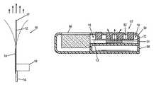
- FIGS. 1A and 1Bare top and side views a piezoelectric fan in accordance with an embodiment of the present invention
- FIG. 2is a top view of the piezoelectric fan in FIG. 1 thermally coupled to a heat dissipation device, in accordance with an embodiment of the present invention
- FIG. 3is a perspective, partially cut-away view of a portable computer provided with one or more piezoelectric fans, in accordance with an embodiment of the method of the present invention
- FIG. 4is a perspective, partially cut-away view of a portable computer provided with one or more piezoelectric fans, in accordance with an embodiment of the method of the present invention.
- FIGS. 5 and 6are cross-sectional views of a wireless phone provided with one or more piezoelectric fans, in accordance with embodiments of the method of the present invention.
- Piezoelectric fansare provided to facilitate conduction and forced convection for heat dissipation for space-limited electronic devices in accordance with embodiments of the present invention.
- the fan blade of a piezoelectric fanis thermally coupled to the heat dissipation portion of the thermal management system, such as, but not limited to, the fins of a heat sink, the condenser of a heat pipe, and to the thermal mass of a heat spreader or heat block.
- FIGS. 1A and 1Bare top and side views a piezoelectric fan 10 in accordance with an embodiment of the present invention.
- the piezoelectric fan 10comprises a fan blade 12 with one or more piezoelectric films 14 at a fixed end 16 where the fan blade 12 is fixed with a fan base 18 .
- the fan blade 12is thermally coupled to a portion of a heat dissipation device 19 (shown in phantom).
- Piezoelectric fans 10an oscillating fan blade 12 that are driven at resonance by a piezoelectric bending element.
- the piezoelectric bending elementsuch as a piezoceramic film, has operating characteristics such that when stressed electrically by a voltage, its dimensions change. This dimensional change is used to produce bending in the piezoelectric film 14 that also causes the attached fan blade 12 to bend. Bending in alternating directions causes the fan blade 12 to oscillate or vibrate. In free air, high amplitude resonant vibration of the fan blade 12 causes formation of a high velocity unidirectional flow stream. Maximum airflow occurs on axes of the piezoelectric fan's 10 centerline, relative to both width and height dimensions. Air intake is above and below the swept out plane of the fan blade 12 .
- the simple design of the piezoelectric fan 10lends itself to low cost, high volume production.
- Piezoelectric fans 10offer advantages over conventional fan technology. These include good applicability for spot cooling; ultra-light weight; and profile. They produce almost no heat of their own making them ideal for selected enclosures.
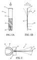
- FIG. 2is a side view of the piezoelectric fan 10 in FIG. 1 in accordance with an embodiment of the present invention.
- the piezoelectric fan 10is thermally coupled to a portion of a heat dissipation device 20 , illustrated as a tip 22 of a heat sink fin.
- the fan blade 12comprises a flexible thermally conductive material adapted to conduct heat away from the heat dissipation device 20 .
- the oscillating motion of the fan blade 12provides forced convection of heat to the environment.
- the fan blade 12is thermally coupled to the heat dissipation device 20 being cooled.
- the fixed end 16 of the fan blade 12is coupled to a heat dissipation device 20 using a process, such as, but not limited to, soldering, thermal conductive 10 adhesive, and brazing.
- the motion of the free end 17 of the fan blade 12enhances the convective heat transfer rate from the fan blade 12 and, secondarily, the heat dissipation device 20 upon which it is thermally coupled.
- heat dissipation device 20It is acknowledged that small enclosures, such as those associated with portable computers and wireless phones, have little space available for the heat dissipation device 20 . However, there are still some remote areas available for a low profile heat dissipation device 20 such as a heat spreader in the form of a thin plate of conductive material.
- the heat spreaderis thermally coupled with the one or more heat producing components.
- the heat spreaderprovides a relatively large, broad surface from which heat can be convected therefrom.
- a heat spreaderis generally effective, though, only if subjected to forced convection.
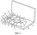
- FIG. 3is a perspective, partially cut-away view of a portable computer 30 provided with one or more piezoelectric fans 10 , in accordance with an embodiment of the method of the present invention.
- the portable computer 30comprises a heat dissipation device 35 thermally coupled to one or more heat-producing microelectronic devices 31 .
- the heat dissipation device 35comprises a heat spreader 37 , a heat pipe 38 and a heat sink 36 , which are known in the art.
- One or more piezoelectric fans 10are coupled to the heat dissipation device 35 in one or more locations.
- the fan blade 12 of one or more piezoelectric fans 10are thermally coupled to the periphery of the heat spreader 37 .
- the fan blade 12 of one or more piezoelectric fans 10is thermally coupled to the heat pipe 38 . In yet another embodiment, the fan blade 12 of one or more piezoelectric fans 10 is thermally coupled to the heat spreader 37 , the heat pipe 38 , and the heat sink fins 39 .
- the fan blade 12 of the one or more piezoelectric fans 10conducts heat from the heat dissipation device 35 to the surrounding air.
- the oscillating movement of the fan blade 12 through the surrounding airforced convection for the fan blade 12 .
- the extra air movement provided by the piezoelectric fans 10reduces the total thermal resistance of the heat dissipation device 35 .
- FIG. 4is a perspective, partially cut-away view of a portable computer 30 provided with one or more piezoelectric fans 10 , in accordance with an embodiment of the method of the present invention.
- a display section 33 of the portable computer 30presents a location to house components of a heat dissipation device 45 .
- the heat dissipation device 45comprises an evaporator 48 in the base section 32 thermally coupled with one or more microelectronic devices 31 , interconnected in a continuous loop with a flat plate vapor chamber 40 located behind the display screen (not shown) in the display section 33 , with flexible connections 44 between the evaporator 48 in the base section 32 and the vapor chamber 40 in the display section 33 hingedly coupled to the base section 32 .
- the fan blades 12 of one or more piezoelectric fans 10are thermally interconnected about the periphery of the vapor chamber 40 .
- the fan blades 12conduct heat from the vapor chamber 40 , and the oscillation of the fan blades 12 provides forced convection of the heat from the fan blade 12 and, secondarily, from the vapor chamber 40 .
- the evaporator 48includes, but not limited to, oscillating heat pipe or conventional heat pipe, to move thermal energy from the evaporator 48 to the vapor chamber 40 .
- Evaporators 48 and vapor chambers 40are known in the art and commonly contain a cooling fluid, such as water, fluorocarbon liquid, freon, silicone fluid, and the like (not shown), which transports thermal energy from the evaporator to the vapor chamber.
- FIG. 5is a cross-sectional view of a wireless phone 50 provided with one or more piezoelectric fans 10 , in accordance with an embodiment of the method of the present invention.
- the wireless phone 50comprises an enclosure 54 , display electronics 56 , a battery 58 , a keypad 57 , and a circuit substrate 52 .
- the very small volume within a wireless phone enclosure 54requires efficient utilization of space to contain the various components.
- the circuit substrate 52provides mounting and electrical interconnection for the microelectronic package 31 .
- Heat from the microelectronic package 31is conducted to the circuit substrate 52 that is made thermally conductive for that purpose. Heat is then released by convection to the environment.
- heat dissipation from the circuit substrate 52is less effective as the size of the circuit substrate 52 is reduced for the smaller sizes of wireless phones.
- the limited space inside the enclosure 54is not, by itself, sufficient to support thermal convection of the heat produced by advanced microelectronic packages 31 .
- the microelectronic package 31is thermally interconnected with a heat spreader 53 , and the heat spreader 53 is provided with one or more piezoelectric fans 10 about the periphery.
- the fan blades 12 of the piezoelectric fans 10are thermally coupled with the heat spreader 53 , such that heat is conducted from the microelectronic device 31 to the heat spreader 53 and from the heat spreader 53 to the fan blade 12 and dissipated by convection to the environment by the oscillating fan blade 12 .
- the air flowwill provide convective cooling on the heat spreader 53 and circuit substrate 52 .
- FIG. 6is a cross-sectional view of a wireless phone 50 provided with one or more piezoelectric fans 10 thermally coupled to the circuit substrate 52 .
- the fan blades 12are thermally coupled about the periphery of the heat conductive circuit substrate 52 such that heat is conducted from the microelectronic device 31 to the circuit substrate 52 and from the circuit substrate 52 to the fan blade 12 and dissipated by convection to the environment by the oscillating fan blade 12 . Secondarily, the air flow will provide convective cooling for the circuit substrate 52 .
- Piezoelectric fanshave very low power requirements to drive the fan blade into oscillation. Also, piezoelectric fans present a low profile whether idle or in operation, and therefore, are ideally suited for limited space situations.
- Piezoelectric fans used in accordance with embodiments of the present inventionsignificantly reduce the heat dissipation device thermal resistance ( ⁇ sa ) for applications such as, but not limited to, portable computers and wireless phones, as they effectively provide either a parallel path or additional surface area for heat dissipation through heat conduction and provide forced convention.
- Thermally conductive components discussed hereinincluding, but not limited to, the fan blade, heat spreader, evaporator, vapor chamber, heat pipe, and heat sink, are fabricated from thermally conductive material, such as, but not limited to, copper, copper alloys, aluminum, and aluminum alloys.
Landscapes
- Engineering & Computer Science (AREA)
- Mechanical Engineering (AREA)
- General Engineering & Computer Science (AREA)
- Physics & Mathematics (AREA)
- Condensed Matter Physics & Semiconductors (AREA)
- General Physics & Mathematics (AREA)
- Computer Hardware Design (AREA)
- Microelectronics & Electronic Packaging (AREA)
- Power Engineering (AREA)
- Cooling Or The Like Of Electrical Apparatus (AREA)
- Structures Of Non-Positive Displacement Pumps (AREA)
Abstract
Description
The present invention relates to the thermal management of electronic components and, more particularly, to forced convection using vibrating blades.
Many of today's electronic goods contain one or more electronic components that operate at elevated temperature requiring some type of thermal management system. By way of example, portable computers and wireless phones have one or more microelectronic packages that generate a considerable amount of thermal energy dissipated as heat. An example of a microelectronic package is an integrated circuit microprocessor, an example of which is a central processing unit (CPU) for the computer system.
In some cases, the heat can be managed with a thermally coupled heat sink, which provides a large surface area for dissipation of heat through convection. Heat sinks are generally formed from a material having a high thermal conductivity. Heat sinks couple with the microelectronic package and comprises a plurality of fins or pins through which air may pass to dissipate the heat. In many cases, a fan is attached to the heat sink to provide forced convection for more efficient heat dissipation.
With the drive for smaller electronic products, the available space is very limited to house a heat sink and fan. In some cases the heat sink is remotely located or a different thermal management solution used. For example, in some portable computers, such as laptop computers, heat generated from the electronic components is carried via heat pipe to a remote heat sink, commonly located in the hinge connecting the display to the base.
In some cases, the heat dissipation device is a flat plate known as a heat spreader. The amount of thermal dissipation remains limited in these devices due to high thermal resistance related to the thermal mass of a solid metal plate and the limited efficiencies of passive convection.
In yet another example, the microelectronic components within a wireless phone generate significant amounts of heat during use that must be dissipated to prevent damage. The concentrated heating and small size of the enclosure make thermal management a significant issue in wireless phone design.
New apparatus and methods are needed for providing thermal management of space-limited electronic devices. They must provide for small scale integration, be capable of managing the thermal requirements of the electronic device, not significantly impact the electrical power consumption of the device, and be inexpensive to manufacture.
In the following detailed description, reference is made to the accompanying drawings which form a part hereof wherein like numerals designate like parts throughout, and in which is shown by way of illustration specific embodiments in which the invention may be practiced. It is to be understood that other embodiments may be utilized and structural or logical changes may be made without departing from the scope of the present invention. Therefore, the following detailed description is not to be taken in a limiting sense, and the scope of the present invention is defined by the appended claims and their equivalents.
Piezoelectric fans are provided to facilitate conduction and forced convection for heat dissipation for space-limited electronic devices in accordance with embodiments of the present invention. The fan blade of a piezoelectric fan is thermally coupled to the heat dissipation portion of the thermal management system, such as, but not limited to, the fins of a heat sink, the condenser of a heat pipe, and to the thermal mass of a heat spreader or heat block.
Thefan blade 12 is thermally coupled to theheat dissipation device 20 being cooled. The fixedend 16 of thefan blade 12 is coupled to aheat dissipation device 20 using a process, such as, but not limited to, soldering, thermal conductive10 adhesive, and brazing. The motion of thefree end 17 of thefan blade 12 enhances the convective heat transfer rate from thefan blade 12 and, secondarily, theheat dissipation device 20 upon which it is thermally coupled.
It is acknowledged that small enclosures, such as those associated with portable computers and wireless phones, have little space available for theheat dissipation device 20. However, there are still some remote areas available for a low profileheat dissipation device 20 such as a heat spreader in the form of a thin plate of conductive material. The heat spreader is thermally coupled with the one or more heat producing components. The heat spreader provides a relatively large, broad surface from which heat can be convected therefrom. A heat spreader is generally effective, though, only if subjected to forced convection.
Thefan blade 12 of the one or morepiezoelectric fans 10 conducts heat from theheat dissipation device 35 to the surrounding air. The oscillating movement of thefan blade 12 through the surrounding air forced convection for thefan blade 12. The extra air movement provided by thepiezoelectric fans 10 reduces the total thermal resistance of theheat dissipation device 35.
Thefan blades 12 of one or morepiezoelectric fans 10 are thermally interconnected about the periphery of thevapor chamber 40. Thefan blades 12 conduct heat from thevapor chamber 40, and the oscillation of thefan blades 12 provides forced convection of the heat from thefan blade 12 and, secondarily, from thevapor chamber 40.
Theevaporator 48 includes, but not limited to, oscillating heat pipe or conventional heat pipe, to move thermal energy from theevaporator 48 to thevapor chamber 40.Evaporators 48 andvapor chambers 40 are known in the art and commonly contain a cooling fluid, such as water, fluorocarbon liquid, freon, silicone fluid, and the like (not shown), which transports thermal energy from the evaporator to the vapor chamber.
Thecircuit substrate 52 provides mounting and electrical interconnection for themicroelectronic package 31. Heat from themicroelectronic package 31 is conducted to thecircuit substrate 52 that is made thermally conductive for that purpose. Heat is then released by convection to the environment. However, heat dissipation from thecircuit substrate 52 is less effective as the size of thecircuit substrate 52 is reduced for the smaller sizes of wireless phones. Further, the limited space inside theenclosure 54 is not, by itself, sufficient to support thermal convection of the heat produced by advanced microelectronic packages31.
In an embodiment in accordance with the present invention, themicroelectronic package 31 is thermally interconnected with aheat spreader 53, and theheat spreader 53 is provided with one or morepiezoelectric fans 10 about the periphery. Thefan blades 12 of thepiezoelectric fans 10 are thermally coupled with theheat spreader 53, such that heat is conducted from themicroelectronic device 31 to theheat spreader 53 and from theheat spreader 53 to thefan blade 12 and dissipated by convection to the environment by theoscillating fan blade 12. Secondarily, the air flow will provide convective cooling on theheat spreader 53 andcircuit substrate 52.
Piezoelectric fans have very low power requirements to drive the fan blade into oscillation. Also, piezoelectric fans present a low profile whether idle or in operation, and therefore, are ideally suited for limited space situations.
Piezoelectric fans used in accordance with embodiments of the present invention significantly reduce the heat dissipation device thermal resistance (θsa) for applications such as, but not limited to, portable computers and wireless phones, as they effectively provide either a parallel path or additional surface area for heat dissipation through heat conduction and provide forced convention.
Thermally conductive components discussed herein, including, but not limited to, the fan blade, heat spreader, evaporator, vapor chamber, heat pipe, and heat sink, are fabricated from thermally conductive material, such as, but not limited to, copper, copper alloys, aluminum, and aluminum alloys.
Although specific embodiments have been illustrated and described herein for purposes of description of the preferred embodiment, it will be appreciated by those of ordinary skill in the art that a wide variety of alternate and/or equivalent implementations calculated to achieve the same purposes may be substituted for the specific embodiment shown and described without departing from the scope of the present invention. Those with skill in the art will readily appreciate that the present invention may be implemented in a very wide variety of embodiments. This application is intended to cover any adaptations or variations of the embodiments discussed herein. Therefore, it is manifestly intended that this invention be limited only by the claims and the equivalents thereof.
Claims (19)
1. An apparatus, comprising:
a heat source to generate heat;
a heat dissipation component thermally coupled to the heat source, the heat dissipation component having a planar shaped component defined by a first and a second surface, the first and the second surfaces being parallel to each other and bordered by at least one end, the first and second surfaces having surface areas greater than the at least one end, the planar shaped heat dissipation component to receive and transfer the generated heat away from the heat source; and
a piezoelectric fan coupled to the at least one end of the planar shaped heat dissipation component, the piezoelectric fan to facilitate dissipation of the transferred heat from the heat source, the piezoelectric fan having a substantially planar shape with a first and a second end, the first end being coupled to the at least one end of the heat dissipation component and the second end being located away from the at least one end of the heat dissipation component relative to the first end.
2. The apparatus ofclaim 1 , wherein the first surface of the planar shaped heat dissipation component is located along a plane and the piezoelectric fan extends outwardly from the at least one end of the heat dissipation component in a direction that is substantially parallel with the plane.
3. The apparatus ofclaim 1 , wherein the piezoelectric fan includes a blade, at least a portion of the blade coupled to a piezoelectric film element.
4. The apparatus ofclaim 1 , wherein the apparatus is a laptop computer.
5. The apparatus ofclaim 4 , wherein the planar shaped heat dissipation component is a vapor chamber.
6. The apparatus ofclaim 4 , wherein the planar shaped heat dissipation component is coupled to the heat source via at least one component selected from the group consisting of a heat sink, evaporator and heat pipe.
7. The apparatus ofclaim 4 , wherein the planar shaped heat dissipation component is located at a display section and the heat source is located at a base section.
8. The apparatus ofclaim 7 , wherein the heat source located at the base section is flexibly coupled to the planar shaped heat dissipation component located at the display section by a heat pipe at a bendable point where the base section is coupled to the display section.
9. The apparatus ofclaim 1 , wherein the apparatus is a wireless phone.
10. The apparatus ofclaim 9 , wherein the heat source having a third surface, the third surface being substantially parallel to the first surface and coupled at least partially to the first surface of the heat dissipation component, the first surface having a surface area that is greater than the third surface of the heat source.
11. The apparatus ofclaim 9 , wherein the planar shaped heat dissipation component is a component selected from the group consisting of a heat spreader and a circuit substrate.
12. The apparatus ofclaim 1 , wherein the heat source is a microelectronic package.
13. A method of operation for dissipating heat remotely from a heat source in an electronic device, comprising:
generating heat from the heat source;
transferring the generated heat to a planar shaped heat dissipation component, the planar shaped heat dissipation component having a planar shaped component having a first and a second surface that are substantially parallel to each other and bordered by at least one end, the first and second surfaces having surface areas greater than the at least one end; and
dissipating the transferred heat from the planar shaped heat dissipation component by energizing at least a portion of a piezoelectric fan coupled to the at least one end of the planar shaped heat dissipation component, the piezoelectric fan having a planar shape with a first end and a second end, the first end being coupled to the at least one end of the heat dissipation component and the second end being a free end located away from the at least one end of the heat dissipation component relative to the first end, and the second end of the piezoelectric fan oscillating when the at least a portion of the piezoelectric fan is energized to facilitate the dissipation of the transferred heat from the heat dissipation component.
14. The method ofclaim 13 , wherein the electronic device is a lap top computer and said transferring comprises of transferring the generated heat to the planar shaped heat dissipation component through at least one component selected from the group consisting of a heat sink, evaporator and heat pipe.
15. The method ofclaim 13 , wherein the electronic device is a wireless phone and said transferring comprises of transferring the generated heat to a planar shaped heat dissipation component selected from the group consisting of a heat spreader and circuit substrate.
16. The method ofclaim 15 , wherein the heat source includes a third surface, the third surface with a smaller surface area than the first surface of the planar shaped heat dissipation component, the third surface is substantially parallel to the first surface and at least partially coupled to the first surface, and wherein said transferring comprises transferring the generated heat from the third surface to at least a portion of the first surface of the planar shaped heat dissipation component.
17. The method ofclaim 13 , wherein the piezoelectric fan comprises of a blade that is at least partially coupled to a piezoelectric film element and said dissipating comprises energizing the piezoelectric film element.
18. The method ofclaim 13 , wherein the piezoelectric fan comprises of a blade and said dissipating comprises of oscillating the blade.
19. The method ofclaim 18 , wherein said oscillating the blade to facilitate air circulation around the blade.
Priority Applications (1)
| Application Number | Priority Date | Filing Date | Title |
|---|---|---|---|
| US10/337,909US7031155B2 (en) | 2003-01-06 | 2003-01-06 | Electronic thermal management |
Applications Claiming Priority (1)
| Application Number | Priority Date | Filing Date | Title |
|---|---|---|---|
| US10/337,909US7031155B2 (en) | 2003-01-06 | 2003-01-06 | Electronic thermal management |
Publications (2)
| Publication Number | Publication Date |
|---|---|
| US20040253130A1 US20040253130A1 (en) | 2004-12-16 |
| US7031155B2true US7031155B2 (en) | 2006-04-18 |
Family
ID=33510246
Family Applications (1)
| Application Number | Title | Priority Date | Filing Date |
|---|---|---|---|
| US10/337,909Expired - Fee RelatedUS7031155B2 (en) | 2003-01-06 | 2003-01-06 | Electronic thermal management |
Country Status (1)
| Country | Link |
|---|---|
| US (1) | US7031155B2 (en) |
Cited By (69)
| Publication number | Priority date | Publication date | Assignee | Title |
|---|---|---|---|---|
| US20050105012A1 (en)* | 2003-10-28 | 2005-05-19 | Kim Sung K. | Display |
| US20050231914A1 (en)* | 2002-08-16 | 2005-10-20 | Kazuyuki Mikubo | Cooling device for electronic apparatus |
| US20060102323A1 (en)* | 2003-02-14 | 2006-05-18 | Prosenjit Ghosh | Radially shaped heat pipe |
| US20060138905A1 (en)* | 2004-12-28 | 2006-06-29 | Gonzales Christopher A | Piezoelectric fan for an integrated circuit chip |
| US20060268534A1 (en)* | 2005-05-31 | 2006-11-30 | Intel Corporation | Wireless device enclosure using piezoelectric cooling structures |
| US20070058103A1 (en)* | 2005-09-12 | 2007-03-15 | Denso Corporation | Liquid crystal display apparatus |
| US20070146993A1 (en)* | 2005-12-23 | 2007-06-28 | Intel Corporation | Method, apparatus and computer system for enhancement of thermal energy transfer |
| US20080238256A1 (en)* | 2007-03-30 | 2008-10-02 | Javier Leija | Dual direction rake piezo actuator |
| US20080291614A1 (en)* | 2007-05-23 | 2008-11-27 | Tatsuya Sakata | Display device |
| US20090034197A1 (en)* | 2007-06-30 | 2009-02-05 | Javier Leija | Heatsink, method of manufacturing same, and microelectronic package containing same |
| US20090080157A1 (en)* | 2007-09-20 | 2009-03-26 | Krishnakumar Varadarajan | Method, apparatus and computer system for air mover lid cooling |
| US20090279255A1 (en)* | 2008-05-09 | 2009-11-12 | Ioan Sauciuc | Piezo fans for cooling an electronic device |
| US20100038994A1 (en)* | 2006-10-04 | 2010-02-18 | Bernhard Eichhorner | Switched mode power supply |
| US20110014069A1 (en)* | 2008-03-25 | 2011-01-20 | Murata Manufacturing Co., Ltd. | Piezoelectric fan device and air-cooling apparatus using the piezoelectric fan device |
| US20110063800A1 (en)* | 2009-09-14 | 2011-03-17 | Kwan Woo Park | Heat dissipating device |
| US20110090686A1 (en)* | 2009-10-20 | 2011-04-21 | Cree Led Lighting Solutions Inc. | Compact Heat Sinks and Solid State Lamp Incorporating Same |
| US20110089838A1 (en)* | 2009-10-20 | 2011-04-21 | Cree Led Lighting Solutions, Inc. | Heat sinks and lamp incorporating same |
| US20110122582A1 (en)* | 2009-11-20 | 2011-05-26 | Kwan Woo Park | Heat dissipating device |
| US20120202373A1 (en)* | 2011-02-04 | 2012-08-09 | Sony Ericsson Mobile Communications Ab | Temperature control arrangement |
| US20140104788A1 (en)* | 2012-10-16 | 2014-04-17 | Abb Research Ltd | Cooled electrical assembly |
| US20140166235A1 (en)* | 2012-12-13 | 2014-06-19 | Goodrich Lighting Systems Gmbh | Device for generating an airflow for cooling a heat dissipating electronic element such as an led |
| US20140268573A1 (en)* | 2013-03-13 | 2014-09-18 | Elwha Llc | Management of exterior temperatures encountered by user of a portable electronic device in response to an inferred user contact with the portable electronic device |
| US20150055295A1 (en)* | 2013-08-22 | 2015-02-26 | Asia Vital Components Co. Ltd. | Heat dissipation device |
| US8998939B2 (en) | 2010-11-05 | 2015-04-07 | Ethicon Endo-Surgery, Inc. | Surgical instrument with modular end effector |
| US9000720B2 (en) | 2010-11-05 | 2015-04-07 | Ethicon Endo-Surgery, Inc. | Medical device packaging with charging interface |
| US9011427B2 (en) | 2010-11-05 | 2015-04-21 | Ethicon Endo-Surgery, Inc. | Surgical instrument safety glasses |
| US9011471B2 (en) | 2010-11-05 | 2015-04-21 | Ethicon Endo-Surgery, Inc. | Surgical instrument with pivoting coupling to modular shaft and end effector |
| US9017851B2 (en) | 2010-11-05 | 2015-04-28 | Ethicon Endo-Surgery, Inc. | Sterile housing for non-sterile medical device component |
| US9039720B2 (en) | 2010-11-05 | 2015-05-26 | Ethicon Endo-Surgery, Inc. | Surgical instrument with ratcheting rotatable shaft |
| US9089338B2 (en) | 2010-11-05 | 2015-07-28 | Ethicon Endo-Surgery, Inc. | Medical device packaging with window for insertion of reusable component |
| US9161803B2 (en) | 2010-11-05 | 2015-10-20 | Ethicon Endo-Surgery, Inc. | Motor driven electrosurgical device with mechanical and electrical feedback |
| US9217542B2 (en) | 2009-10-20 | 2015-12-22 | Cree, Inc. | Heat sinks and lamp incorporating same |
| US9247986B2 (en) | 2010-11-05 | 2016-02-02 | Ethicon Endo-Surgery, Llc | Surgical instrument with ultrasonic transducer having integral switches |
| US9291399B2 (en) | 2013-03-13 | 2016-03-22 | Elwha Llc | Management of exterior temperatures encountered by user of a portable electronic device |
| US9291400B2 (en) | 2013-03-13 | 2016-03-22 | Elwha Llc | Management of exterior temperatures encountered by user of a portable electronic device using multiple heat-rejection elements |
| US9375255B2 (en) | 2010-11-05 | 2016-06-28 | Ethicon Endo-Surgery, Llc | Surgical instrument handpiece with resiliently biased coupling to modular shaft and end effector |
| US9381058B2 (en) | 2010-11-05 | 2016-07-05 | Ethicon Endo-Surgery, Llc | Recharge system for medical devices |
| US9421062B2 (en) | 2010-11-05 | 2016-08-23 | Ethicon Endo-Surgery, Llc | Surgical instrument shaft with resiliently biased coupling to handpiece |
| US9526921B2 (en) | 2010-11-05 | 2016-12-27 | Ethicon Endo-Surgery, Llc | User feedback through end effector of surgical instrument |
| US9597143B2 (en) | 2010-11-05 | 2017-03-21 | Ethicon Endo-Surgery, Llc | Sterile medical instrument charging device |
| US9649150B2 (en) | 2010-11-05 | 2017-05-16 | Ethicon Endo-Surgery, Llc | Selective activation of electronic components in medical device |
| US20170181316A1 (en)* | 2015-12-18 | 2017-06-22 | Hsien-Chin SU | Heat dissipating device and swing structure thereof |
| US9782214B2 (en) | 2010-11-05 | 2017-10-10 | Ethicon Llc | Surgical instrument with sensor and powered control |
| US9782215B2 (en) | 2010-11-05 | 2017-10-10 | Ethicon Endo-Surgery, Llc | Surgical instrument with ultrasonic transducer having integral switches |
| US9943008B2 (en) | 2016-03-31 | 2018-04-10 | Qualcomm Incorporated | Thermal modulation of an electronic device |
| US10030863B2 (en) | 2011-04-19 | 2018-07-24 | Cree, Inc. | Heat sink structures, lighting elements and lamps incorporating same, and methods of making same |
| US10085792B2 (en) | 2010-11-05 | 2018-10-02 | Ethicon Llc | Surgical instrument with motorized attachment feature |
| US10136938B2 (en) | 2014-10-29 | 2018-11-27 | Ethicon Llc | Electrosurgical instrument with sensor |
| US10249459B2 (en)* | 2016-09-19 | 2019-04-02 | Eaton Intelligent Power Limited | Advanced cooling system for electrical equipment |
| US10378749B2 (en) | 2012-02-10 | 2019-08-13 | Ideal Industries Lighting Llc | Lighting device comprising shield element, and shield element |
| US10537380B2 (en) | 2010-11-05 | 2020-01-21 | Ethicon Llc | Surgical instrument with charging station and wireless communication |
| US10660695B2 (en) | 2010-11-05 | 2020-05-26 | Ethicon Llc | Sterile medical instrument charging device |
| US10881448B2 (en) | 2010-11-05 | 2021-01-05 | Ethicon Llc | Cam driven coupling between ultrasonic transducer and waveguide in surgical instrument |
| US10959769B2 (en) | 2010-11-05 | 2021-03-30 | Ethicon Llc | Surgical instrument with slip ring assembly to power ultrasonic transducer |
| US10973563B2 (en) | 2010-11-05 | 2021-04-13 | Ethicon Llc | Surgical instrument with charging devices |
| US20210183739A1 (en)* | 2019-12-17 | 2021-06-17 | Frore Systems Inc. | Airflow control in active cooling systems |
| WO2021244220A1 (en)* | 2020-06-04 | 2021-12-09 | 中兴通讯股份有限公司 | Heat dissipation assembly, heat dissipation structure and heat dissipation method therefor, and electronic device and apparatus |
| US11293459B2 (en)* | 2018-08-07 | 2022-04-05 | National Chiao Tung University | Fan device |
| US11432433B2 (en)* | 2019-12-06 | 2022-08-30 | Frore Systems Inc. | Centrally anchored MEMS-based active cooling systems |
| US11456234B2 (en) | 2018-08-10 | 2022-09-27 | Frore Systems Inc. | Chamber architecture for cooling devices |
| US11503742B2 (en)* | 2019-12-06 | 2022-11-15 | Frore Systems Inc. | Engineered actuators usable in MEMS active cooling devices |
| US20230030322A1 (en)* | 2021-07-09 | 2023-02-02 | Frore Systems Inc. | Anchor and cavity configuration for mems-based cooling systems |
| US11765863B2 (en) | 2020-10-02 | 2023-09-19 | Frore Systems Inc. | Active heat sink |
| US11796262B2 (en) | 2019-12-06 | 2023-10-24 | Frore Systems Inc. | Top chamber cavities for center-pinned actuators |
| US11802554B2 (en) | 2019-10-30 | 2023-10-31 | Frore Systems Inc. | MEMS-based airflow system having a vibrating fan element arrangement |
| US12029005B2 (en) | 2019-12-17 | 2024-07-02 | Frore Systems Inc. | MEMS-based cooling systems for closed and open devices |
| US12089374B2 (en)* | 2018-08-10 | 2024-09-10 | Frore Systems Inc. | MEMS-based active cooling systems |
| US12193192B2 (en) | 2019-12-06 | 2025-01-07 | Frore Systems Inc. | Cavities for center-pinned actuator cooling systems |
| US20250079571A1 (en)* | 2023-08-29 | 2025-03-06 | C-Tech United Corporation | Thermal management module |
Families Citing this family (24)
| Publication number | Priority date | Publication date | Assignee | Title |
|---|---|---|---|---|
| US20050180109A1 (en)* | 2002-04-16 | 2005-08-18 | Yoshiro Miyazaki | Self-excited vibration heat pipe and computer with the heat pipe |
| US6801430B1 (en)* | 2003-05-09 | 2004-10-05 | Intel Corporation | Actuation membrane to reduce an ambient temperature of heat generating device |
| JP2006116399A (en)* | 2004-10-20 | 2006-05-11 | Citizen Electronics Co Ltd | Flexural vibration exciter |
| GB0504361D0 (en)* | 2005-03-03 | 2005-04-06 | Smiths Group Plc | Detection apparatus |
| US20060256531A1 (en)* | 2005-05-13 | 2006-11-16 | Intel Corporation | Thermal solution with isolation layer |
| US7321184B2 (en)* | 2005-08-09 | 2008-01-22 | Intel Corporation | Rake shaped fan |
| US20070090726A1 (en)* | 2005-10-24 | 2007-04-26 | Morris Grant A | Piezoelectric fan |
| US20080137289A1 (en)* | 2006-12-08 | 2008-06-12 | General Electric Company | Thermal management system for embedded environment and method for making same |
| US10670001B2 (en)* | 2008-02-21 | 2020-06-02 | Clean Energy Labs, Llc | Energy conversion system including a ballistic rectifier assembly and uses thereof |
| CN102150485A (en)* | 2008-09-12 | 2011-08-10 | 皇家飞利浦电子股份有限公司 | Device provided with a gap-like space and a synthetic jet generator coupled there-to |
| CN102130081A (en)* | 2010-01-12 | 2011-07-20 | 富瑞精密组件(昆山)有限公司 | Heat-radiating device and air current generating device thereof |
| US9017849B2 (en)* | 2010-11-05 | 2015-04-28 | Ethicon Endo-Surgery, Inc. | Power source management for medical device |
| EP2509196A1 (en)* | 2011-04-07 | 2012-10-10 | Siemens Aktiengesellschaft | Stator arrangement |
| DE102012200925A1 (en)* | 2012-01-23 | 2013-07-25 | Siemens Aktiengesellschaft | Electric power transmission device with a movable blade and method for moving a sheet |
| US11156235B2 (en)* | 2012-07-05 | 2021-10-26 | Tai-Her Yang | Thermal transferring method and structural device utilizing thermal energy body performing vibration displacement (relative) to fluid |
| CN103857225B (en)* | 2012-12-03 | 2017-03-01 | 联想(北京)有限公司 | A kind of electronic equipment |
| US9800323B2 (en)* | 2015-03-13 | 2017-10-24 | Mission Microwave Technologies, Inc. | Satellite transmitter system |
| EP3507140B1 (en)* | 2016-09-02 | 2020-10-28 | Gentex Corporation | Cooling device for rearview assembly |
| US10390456B2 (en) | 2016-11-07 | 2019-08-20 | Rockwell Automation Technologies, Inc. | Controller with fan monitoring and control |
| US10746959B2 (en)* | 2017-02-27 | 2020-08-18 | Gentex Corporation | Fanless cooling system for full display mirror |
| CN111918792B (en) | 2018-03-27 | 2023-09-26 | 金泰克斯公司 | Full display mirror with integrated cooling system |
| CN110162157A (en)* | 2019-03-29 | 2019-08-23 | 联想(北京)有限公司 | Cooling system |
| DE102021119120A1 (en)* | 2020-08-12 | 2022-02-17 | Defond Components Limited | COOLING SYSTEM FOR COOLING AN ELECTRONIC COMPONENT OF AN ELECTRICAL DEVICE |
| CN112714596A (en)* | 2020-12-24 | 2021-04-27 | 常州威图流体科技有限公司 | Oscillating radiating fin |
Citations (29)
| Publication number | Priority date | Publication date | Assignee | Title |
|---|---|---|---|---|
| US4595338A (en)* | 1983-11-17 | 1986-06-17 | Piezo Electric Products, Inc. | Non-vibrational oscillating blade piezoelectric blower |
| US4751713A (en)* | 1987-07-31 | 1988-06-14 | Hughes Aircraft Company | Gas laser having a piezoelectric fan |
| US4780062A (en)* | 1985-10-09 | 1988-10-25 | Murata Manufacturing Co., Ltd. | Piezoelectric fan |
| US4834619A (en)* | 1987-11-10 | 1989-05-30 | The Boeing Company | Ducted oscillatory blade fan |
| US4923000A (en)* | 1989-03-03 | 1990-05-08 | Microelectronics And Computer Technology Corporation | Heat exchanger having piezoelectric fan means |
| US5008582A (en)* | 1988-01-29 | 1991-04-16 | Kabushiki Kaisha Toshiba | Electronic device having a cooling element |
| JPH0465864A (en)* | 1990-07-06 | 1992-03-02 | Toshiba Ceramics Co Ltd | Heat sink |
| US5381950A (en)* | 1993-10-20 | 1995-01-17 | American Standard Inc. | Zone sensor or thermostat with forced air |
| US5634351A (en)* | 1994-03-24 | 1997-06-03 | Aavid Laboratories, Inc. | Two-phase cooling system for a laptop computer lid |
| US5861703A (en)* | 1997-05-30 | 1999-01-19 | Motorola Inc. | Low-profile axial-flow single-blade piezoelectric fan |
| US5921757A (en)* | 1996-05-27 | 1999-07-13 | Honda Giken Kogyo Kabushiki Kaisha | Piezoelectric fan |
| US6078502A (en)* | 1996-04-01 | 2000-06-20 | Lsi Logic Corporation | System having heat dissipating leadframes |
| US6353295B1 (en)* | 1999-01-20 | 2002-03-05 | Philips Electronics North America Corporation | Lamp electronic ballast with a piezoelectric cooling fan |
| US20020074649A1 (en) | 2000-12-14 | 2002-06-20 | Intel Corporation | Electronic assembly with high capacity thermal interface and methods of manufacture |
| US20020080584A1 (en) | 2000-12-22 | 2002-06-27 | Intel Corporation. | Integrated vapor chamber heat sink and spreader and an embedded direct heat pipe attachment |
| US6469381B1 (en) | 2000-09-29 | 2002-10-22 | Intel Corporation | Carbon-carbon and/or metal-carbon fiber composite heat spreader |
| US6549407B1 (en) | 2001-12-27 | 2003-04-15 | Intel Corporation | Heat exchanger retention mechanism |
| US20030081383A1 (en) | 2001-10-29 | 2003-05-01 | Intel Corporation | Composite fins for heatsinks |
| US6561267B2 (en) | 2001-09-28 | 2003-05-13 | Intel Corporation | Heat sink and electronic circuit module including the same |
| US6609561B2 (en) | 2001-12-21 | 2003-08-26 | Intel Corporation | Tunnel-phase change heat exchanger |
| US6646874B2 (en) | 2001-06-12 | 2003-11-11 | Intel Corporation | Mobile computer system with detachable thermoelectric module for enhanced cooling capability in a docking station |
| US6650542B1 (en) | 2003-01-06 | 2003-11-18 | Intel Corporation | Piezoelectric actuated jet impingement cooling |
| US6713942B2 (en)* | 2001-05-23 | 2004-03-30 | Purdue Research Foundation | Piezoelectric device with feedback sensor |
| US20040070943A1 (en) | 2001-10-29 | 2004-04-15 | Intel Corporation | Composite fins for heat sinks |
| US6770966B2 (en) | 2001-07-31 | 2004-08-03 | Intel Corporation | Electronic assembly including a die having an integrated circuit and a layer of diamond to transfer heat |
| US6785134B2 (en) | 2003-01-06 | 2004-08-31 | Intel Corporation | Embedded liquid pump and microchannel cooling system |
| US6795311B2 (en) | 2001-12-28 | 2004-09-21 | Intel Corporation | Method and apparatus for cooling portable computers |
| US20040188817A1 (en) | 2003-03-31 | 2004-09-30 | Intel Corporation | Apparatus and method to minimize thermal impedance using copper on die backside |
| US20040187501A1 (en) | 2003-03-27 | 2004-09-30 | Intel Corporation | Phase-change refrigeration apparatus with thermoelectric cooling element and methods |
- 2003
- 2003-01-06USUS10/337,909patent/US7031155B2/ennot_activeExpired - Fee Related
Patent Citations (35)
| Publication number | Priority date | Publication date | Assignee | Title |
|---|---|---|---|---|
| US4595338A (en)* | 1983-11-17 | 1986-06-17 | Piezo Electric Products, Inc. | Non-vibrational oscillating blade piezoelectric blower |
| US4780062A (en)* | 1985-10-09 | 1988-10-25 | Murata Manufacturing Co., Ltd. | Piezoelectric fan |
| US4751713A (en)* | 1987-07-31 | 1988-06-14 | Hughes Aircraft Company | Gas laser having a piezoelectric fan |
| US4834619A (en)* | 1987-11-10 | 1989-05-30 | The Boeing Company | Ducted oscillatory blade fan |
| US5008582A (en)* | 1988-01-29 | 1991-04-16 | Kabushiki Kaisha Toshiba | Electronic device having a cooling element |
| US4923000A (en)* | 1989-03-03 | 1990-05-08 | Microelectronics And Computer Technology Corporation | Heat exchanger having piezoelectric fan means |
| JPH0465864A (en)* | 1990-07-06 | 1992-03-02 | Toshiba Ceramics Co Ltd | Heat sink |
| US5381950A (en)* | 1993-10-20 | 1995-01-17 | American Standard Inc. | Zone sensor or thermostat with forced air |
| US5634351A (en)* | 1994-03-24 | 1997-06-03 | Aavid Laboratories, Inc. | Two-phase cooling system for a laptop computer lid |
| US6078502A (en)* | 1996-04-01 | 2000-06-20 | Lsi Logic Corporation | System having heat dissipating leadframes |
| US5921757A (en)* | 1996-05-27 | 1999-07-13 | Honda Giken Kogyo Kabushiki Kaisha | Piezoelectric fan |
| US5861703A (en)* | 1997-05-30 | 1999-01-19 | Motorola Inc. | Low-profile axial-flow single-blade piezoelectric fan |
| US6353295B1 (en)* | 1999-01-20 | 2002-03-05 | Philips Electronics North America Corporation | Lamp electronic ballast with a piezoelectric cooling fan |
| US6469381B1 (en) | 2000-09-29 | 2002-10-22 | Intel Corporation | Carbon-carbon and/or metal-carbon fiber composite heat spreader |
| US6653730B2 (en) | 2000-12-14 | 2003-11-25 | Intel Corporation | Electronic assembly with high capacity thermal interface |
| US20020074649A1 (en) | 2000-12-14 | 2002-06-20 | Intel Corporation | Electronic assembly with high capacity thermal interface and methods of manufacture |
| US20040082188A1 (en) | 2000-12-14 | 2004-04-29 | Intel Corporation | Electronic assembly with high capacity thermal interface and methods of manufacture |
| US6706562B2 (en) | 2000-12-14 | 2004-03-16 | Intel Corporation | Electronic assembly with high capacity thermal spreader and methods of manufacture |
| US20020080584A1 (en) | 2000-12-22 | 2002-06-27 | Intel Corporation. | Integrated vapor chamber heat sink and spreader and an embedded direct heat pipe attachment |
| US6661660B2 (en) | 2000-12-22 | 2003-12-09 | Intel Corporation | Integrated vapor chamber heat sink and spreader and an embedded direct heat pipe attachment |
| US6639799B2 (en) | 2000-12-22 | 2003-10-28 | Intel Corporation | Integrated vapor chamber heat sink and spreader and an embedded direct heat pipe attachment |
| US6713942B2 (en)* | 2001-05-23 | 2004-03-30 | Purdue Research Foundation | Piezoelectric device with feedback sensor |
| US6646874B2 (en) | 2001-06-12 | 2003-11-11 | Intel Corporation | Mobile computer system with detachable thermoelectric module for enhanced cooling capability in a docking station |
| US6770966B2 (en) | 2001-07-31 | 2004-08-03 | Intel Corporation | Electronic assembly including a die having an integrated circuit and a layer of diamond to transfer heat |
| US6561267B2 (en) | 2001-09-28 | 2003-05-13 | Intel Corporation | Heat sink and electronic circuit module including the same |
| US6636423B2 (en) | 2001-10-29 | 2003-10-21 | Intel Corporation | Composite fins for heat sinks |
| US20040070943A1 (en) | 2001-10-29 | 2004-04-15 | Intel Corporation | Composite fins for heat sinks |
| US20030081383A1 (en) | 2001-10-29 | 2003-05-01 | Intel Corporation | Composite fins for heatsinks |
| US6609561B2 (en) | 2001-12-21 | 2003-08-26 | Intel Corporation | Tunnel-phase change heat exchanger |
| US6549407B1 (en) | 2001-12-27 | 2003-04-15 | Intel Corporation | Heat exchanger retention mechanism |
| US6795311B2 (en) | 2001-12-28 | 2004-09-21 | Intel Corporation | Method and apparatus for cooling portable computers |
| US6650542B1 (en) | 2003-01-06 | 2003-11-18 | Intel Corporation | Piezoelectric actuated jet impingement cooling |
| US6785134B2 (en) | 2003-01-06 | 2004-08-31 | Intel Corporation | Embedded liquid pump and microchannel cooling system |
| US20040187501A1 (en) | 2003-03-27 | 2004-09-30 | Intel Corporation | Phase-change refrigeration apparatus with thermoelectric cooling element and methods |
| US20040188817A1 (en) | 2003-03-31 | 2004-09-30 | Intel Corporation | Apparatus and method to minimize thermal impedance using copper on die backside |
Non-Patent Citations (1)
| Title |
|---|
| Sauciuc, I., et al., "Spreading in the Heat Sink Base: Phase Change Systems or Solid Metals??," IEEE Transactions on Components and Packaging Technologies, vol. 25, No. 4, Dec. 2002, pp. 621-628. |
Cited By (116)
| Publication number | Priority date | Publication date | Assignee | Title |
|---|---|---|---|---|
| US20050231914A1 (en)* | 2002-08-16 | 2005-10-20 | Kazuyuki Mikubo | Cooling device for electronic apparatus |
| US20080110600A1 (en)* | 2002-08-16 | 2008-05-15 | Nec Corporation | Cooling apparatus for electronic devices |
| US7420807B2 (en)* | 2002-08-16 | 2008-09-02 | Nec Corporation | Cooling device for electronic apparatus |
| US20060102323A1 (en)* | 2003-02-14 | 2006-05-18 | Prosenjit Ghosh | Radially shaped heat pipe |
| US20050105012A1 (en)* | 2003-10-28 | 2005-05-19 | Kim Sung K. | Display |
| US20060138905A1 (en)* | 2004-12-28 | 2006-06-29 | Gonzales Christopher A | Piezoelectric fan for an integrated circuit chip |
| US20060268534A1 (en)* | 2005-05-31 | 2006-11-30 | Intel Corporation | Wireless device enclosure using piezoelectric cooling structures |
| US7248475B2 (en)* | 2005-05-31 | 2007-07-24 | Intel Corporation | Wireless device enclosure using piezoelectric cooling structures |
| US7965340B2 (en)* | 2005-09-12 | 2011-06-21 | Denso Corporation | Liquid crystal display apparatus |
| US20070058103A1 (en)* | 2005-09-12 | 2007-03-15 | Denso Corporation | Liquid crystal display apparatus |
| US20070146993A1 (en)* | 2005-12-23 | 2007-06-28 | Intel Corporation | Method, apparatus and computer system for enhancement of thermal energy transfer |
| US20100038994A1 (en)* | 2006-10-04 | 2010-02-18 | Bernhard Eichhorner | Switched mode power supply |
| US8106567B2 (en)* | 2006-10-04 | 2012-01-31 | Siemens Aktiengesellschaft | Switched mode power supply |
| US20080238256A1 (en)* | 2007-03-30 | 2008-10-02 | Javier Leija | Dual direction rake piezo actuator |
| US7642698B2 (en)* | 2007-03-30 | 2010-01-05 | Intel Corporation | Dual direction rake piezo actuator |
| US7924560B2 (en)* | 2007-05-23 | 2011-04-12 | Sony Corporation | Display device |
| US20080291614A1 (en)* | 2007-05-23 | 2008-11-27 | Tatsuya Sakata | Display device |
| US7692922B2 (en)* | 2007-06-30 | 2010-04-06 | Intel Corporation | Heatsink, method of manufacturing same, and microelectronic package containing same |
| US20090034197A1 (en)* | 2007-06-30 | 2009-02-05 | Javier Leija | Heatsink, method of manufacturing same, and microelectronic package containing same |
| US20090080157A1 (en)* | 2007-09-20 | 2009-03-26 | Krishnakumar Varadarajan | Method, apparatus and computer system for air mover lid cooling |
| US20110014069A1 (en)* | 2008-03-25 | 2011-01-20 | Murata Manufacturing Co., Ltd. | Piezoelectric fan device and air-cooling apparatus using the piezoelectric fan device |
| US20090279255A1 (en)* | 2008-05-09 | 2009-11-12 | Ioan Sauciuc | Piezo fans for cooling an electronic device |
| US7742299B2 (en)* | 2008-05-09 | 2010-06-22 | Intel Corporation | Piezo fans for cooling an electronic device |
| US20110063800A1 (en)* | 2009-09-14 | 2011-03-17 | Kwan Woo Park | Heat dissipating device |
| US8520383B2 (en)* | 2009-09-14 | 2013-08-27 | Lg Electronics Inc. | Heat dissipating device |
| US20110090686A1 (en)* | 2009-10-20 | 2011-04-21 | Cree Led Lighting Solutions Inc. | Compact Heat Sinks and Solid State Lamp Incorporating Same |
| US20110089838A1 (en)* | 2009-10-20 | 2011-04-21 | Cree Led Lighting Solutions, Inc. | Heat sinks and lamp incorporating same |
| US9030120B2 (en) | 2009-10-20 | 2015-05-12 | Cree, Inc. | Heat sinks and lamp incorporating same |
| US9243758B2 (en) | 2009-10-20 | 2016-01-26 | Cree, Inc. | Compact heat sinks and solid state lamp incorporating same |
| US9217542B2 (en) | 2009-10-20 | 2015-12-22 | Cree, Inc. | Heat sinks and lamp incorporating same |
| US20110122582A1 (en)* | 2009-11-20 | 2011-05-26 | Kwan Woo Park | Heat dissipating device |
| US8520384B2 (en)* | 2009-11-20 | 2013-08-27 | Lg Electronics Inc. | Heat dissipating device |
| US9381058B2 (en) | 2010-11-05 | 2016-07-05 | Ethicon Endo-Surgery, Llc | Recharge system for medical devices |
| US10959769B2 (en) | 2010-11-05 | 2021-03-30 | Ethicon Llc | Surgical instrument with slip ring assembly to power ultrasonic transducer |
| US11925335B2 (en) | 2010-11-05 | 2024-03-12 | Cilag Gmbh International | Surgical instrument with slip ring assembly to power ultrasonic transducer |
| US8998939B2 (en) | 2010-11-05 | 2015-04-07 | Ethicon Endo-Surgery, Inc. | Surgical instrument with modular end effector |
| US9000720B2 (en) | 2010-11-05 | 2015-04-07 | Ethicon Endo-Surgery, Inc. | Medical device packaging with charging interface |
| US9011427B2 (en) | 2010-11-05 | 2015-04-21 | Ethicon Endo-Surgery, Inc. | Surgical instrument safety glasses |
| US9011471B2 (en) | 2010-11-05 | 2015-04-21 | Ethicon Endo-Surgery, Inc. | Surgical instrument with pivoting coupling to modular shaft and end effector |
| US9017851B2 (en) | 2010-11-05 | 2015-04-28 | Ethicon Endo-Surgery, Inc. | Sterile housing for non-sterile medical device component |
| US11744635B2 (en) | 2010-11-05 | 2023-09-05 | Cilag Gmbh International | Sterile medical instrument charging device |
| US9039720B2 (en) | 2010-11-05 | 2015-05-26 | Ethicon Endo-Surgery, Inc. | Surgical instrument with ratcheting rotatable shaft |
| US9072523B2 (en) | 2010-11-05 | 2015-07-07 | Ethicon Endo-Surgery, Inc. | Medical device with feature for sterile acceptance of non-sterile reusable component |
| US9089338B2 (en) | 2010-11-05 | 2015-07-28 | Ethicon Endo-Surgery, Inc. | Medical device packaging with window for insertion of reusable component |
| US9095346B2 (en) | 2010-11-05 | 2015-08-04 | Ethicon Endo-Surgery, Inc. | Medical device usage data processing |
| US9161803B2 (en) | 2010-11-05 | 2015-10-20 | Ethicon Endo-Surgery, Inc. | Motor driven electrosurgical device with mechanical and electrical feedback |
| US9192428B2 (en) | 2010-11-05 | 2015-11-24 | Ethicon Endo-Surgery, Inc. | Surgical instrument with modular clamp pad |
| US11690605B2 (en) | 2010-11-05 | 2023-07-04 | Cilag Gmbh International | Surgical instrument with charging station and wireless communication |
| US11389228B2 (en) | 2010-11-05 | 2022-07-19 | Cilag Gmbh International | Surgical instrument with sensor and powered control |
| US9247986B2 (en) | 2010-11-05 | 2016-02-02 | Ethicon Endo-Surgery, Llc | Surgical instrument with ultrasonic transducer having integral switches |
| US10973563B2 (en) | 2010-11-05 | 2021-04-13 | Ethicon Llc | Surgical instrument with charging devices |
| US10143513B2 (en) | 2010-11-05 | 2018-12-04 | Ethicon Llc | Gear driven coupling between ultrasonic transducer and waveguide in surgical instrument |
| US10945783B2 (en) | 2010-11-05 | 2021-03-16 | Ethicon Llc | Surgical instrument with modular shaft and end effector |
| US9308009B2 (en) | 2010-11-05 | 2016-04-12 | Ethicon Endo-Surgery, Llc | Surgical instrument with modular shaft and transducer |
| US10881448B2 (en) | 2010-11-05 | 2021-01-05 | Ethicon Llc | Cam driven coupling between ultrasonic transducer and waveguide in surgical instrument |
| US10660695B2 (en) | 2010-11-05 | 2020-05-26 | Ethicon Llc | Sterile medical instrument charging device |
| US9364279B2 (en) | 2010-11-05 | 2016-06-14 | Ethicon Endo-Surgery, Llc | User feedback through handpiece of surgical instrument |
| US9375255B2 (en) | 2010-11-05 | 2016-06-28 | Ethicon Endo-Surgery, Llc | Surgical instrument handpiece with resiliently biased coupling to modular shaft and end effector |
| US10085792B2 (en) | 2010-11-05 | 2018-10-02 | Ethicon Llc | Surgical instrument with motorized attachment feature |
| US9421062B2 (en) | 2010-11-05 | 2016-08-23 | Ethicon Endo-Surgery, Llc | Surgical instrument shaft with resiliently biased coupling to handpiece |
| US9510895B2 (en) | 2010-11-05 | 2016-12-06 | Ethicon Endo-Surgery, Llc | Surgical instrument with modular shaft and end effector |
| US9526921B2 (en) | 2010-11-05 | 2016-12-27 | Ethicon Endo-Surgery, Llc | User feedback through end effector of surgical instrument |
| US9597143B2 (en) | 2010-11-05 | 2017-03-21 | Ethicon Endo-Surgery, Llc | Sterile medical instrument charging device |
| US9649150B2 (en) | 2010-11-05 | 2017-05-16 | Ethicon Endo-Surgery, Llc | Selective activation of electronic components in medical device |
| US10537380B2 (en) | 2010-11-05 | 2020-01-21 | Ethicon Llc | Surgical instrument with charging station and wireless communication |
| US9782214B2 (en) | 2010-11-05 | 2017-10-10 | Ethicon Llc | Surgical instrument with sensor and powered control |
| US10376304B2 (en) | 2010-11-05 | 2019-08-13 | Ethicon Llc | Surgical instrument with modular shaft and end effector |
| US9782215B2 (en) | 2010-11-05 | 2017-10-10 | Ethicon Endo-Surgery, Llc | Surgical instrument with ultrasonic transducer having integral switches |
| US20120202373A1 (en)* | 2011-02-04 | 2012-08-09 | Sony Ericsson Mobile Communications Ab | Temperature control arrangement |
| US10030863B2 (en) | 2011-04-19 | 2018-07-24 | Cree, Inc. | Heat sink structures, lighting elements and lamps incorporating same, and methods of making same |
| US10378749B2 (en) | 2012-02-10 | 2019-08-13 | Ideal Industries Lighting Llc | Lighting device comprising shield element, and shield element |
| US9313916B2 (en)* | 2012-10-16 | 2016-04-12 | Abb Research Ltd | Cooled electrical assembly |
| US20140104788A1 (en)* | 2012-10-16 | 2014-04-17 | Abb Research Ltd | Cooled electrical assembly |
| US9788457B2 (en)* | 2012-12-13 | 2017-10-10 | Goodrich Lighting Systems Gmbh | Device for generating an airflow for cooling a heat dissipating electronic element such as an LED |
| US20140166235A1 (en)* | 2012-12-13 | 2014-06-19 | Goodrich Lighting Systems Gmbh | Device for generating an airflow for cooling a heat dissipating electronic element such as an led |
| US9320174B2 (en) | 2013-03-13 | 2016-04-19 | Elwha Llc | Management of exterior temperatures encountered by user of a portable electronic device in response to an inferred user contact with the portable electronic device |
| US8971043B2 (en)* | 2013-03-13 | 2015-03-03 | Elwha Llc | Management of exterior temperatures encountered by user of a portable electronic device in response to an inferred user contact with the portable electronic device |
| US9291400B2 (en) | 2013-03-13 | 2016-03-22 | Elwha Llc | Management of exterior temperatures encountered by user of a portable electronic device using multiple heat-rejection elements |
| US9291399B2 (en) | 2013-03-13 | 2016-03-22 | Elwha Llc | Management of exterior temperatures encountered by user of a portable electronic device |
| US20140268573A1 (en)* | 2013-03-13 | 2014-09-18 | Elwha Llc | Management of exterior temperatures encountered by user of a portable electronic device in response to an inferred user contact with the portable electronic device |
| US9367103B2 (en)* | 2013-08-22 | 2016-06-14 | Asia Vital Components Co., Ltd. | Heat dissipation device |
| US20150055295A1 (en)* | 2013-08-22 | 2015-02-26 | Asia Vital Components Co. Ltd. | Heat dissipation device |
| US10136938B2 (en) | 2014-10-29 | 2018-11-27 | Ethicon Llc | Electrosurgical instrument with sensor |
| US20170181316A1 (en)* | 2015-12-18 | 2017-06-22 | Hsien-Chin SU | Heat dissipating device and swing structure thereof |
| US9943008B2 (en) | 2016-03-31 | 2018-04-10 | Qualcomm Incorporated | Thermal modulation of an electronic device |
| US10249459B2 (en)* | 2016-09-19 | 2019-04-02 | Eaton Intelligent Power Limited | Advanced cooling system for electrical equipment |
| US11293459B2 (en)* | 2018-08-07 | 2022-04-05 | National Chiao Tung University | Fan device |
| US11456234B2 (en) | 2018-08-10 | 2022-09-27 | Frore Systems Inc. | Chamber architecture for cooling devices |
| US11830789B2 (en) | 2018-08-10 | 2023-11-28 | Frore Systems Inc. | Mobile phone and other compute device cooling architecture |
| US11784109B2 (en) | 2018-08-10 | 2023-10-10 | Frore Systems Inc. | Method and system for driving piezoelectric MEMS-based active cooling devices |
| US11710678B2 (en) | 2018-08-10 | 2023-07-25 | Frore Systems Inc. | Combined architecture for cooling devices |
| US11532536B2 (en) | 2018-08-10 | 2022-12-20 | Frore Systems Inc. | Mobile phone and other compute device cooling architecture |
| US11735496B2 (en) | 2018-08-10 | 2023-08-22 | Frore Systems Inc. | Piezoelectric MEMS-based active cooling for heat dissipation in compute devices |
| US12089374B2 (en)* | 2018-08-10 | 2024-09-10 | Frore Systems Inc. | MEMS-based active cooling systems |
| US11705382B2 (en) | 2018-08-10 | 2023-07-18 | Frore Systems Inc. | Two-dimensional addessable array of piezoelectric MEMS-based active cooling devices |
| US11802554B2 (en) | 2019-10-30 | 2023-10-31 | Frore Systems Inc. | MEMS-based airflow system having a vibrating fan element arrangement |
| US11510341B2 (en)* | 2019-12-06 | 2022-11-22 | Frore Systems Inc. | Engineered actuators usable in MEMs active cooling devices |
| US12320595B2 (en) | 2019-12-06 | 2025-06-03 | Frore Systems Inc. | Top chamber cavities for center-pinned actuators |
| US20220394883A1 (en)* | 2019-12-06 | 2022-12-08 | Frore Systems Inc. | Engineered actuators usable in mems active cooling devices |
| US12274035B2 (en)* | 2019-12-06 | 2025-04-08 | Frore Systems Inc. | Engineered actuators usable in MEMs active cooling devices |
| US12137540B2 (en) | 2019-12-06 | 2024-11-05 | Frore Systems Inc. | Centrally anchored MEMS-based active cooling systems |
| US11796262B2 (en) | 2019-12-06 | 2023-10-24 | Frore Systems Inc. | Top chamber cavities for center-pinned actuators |
| US11503742B2 (en)* | 2019-12-06 | 2022-11-15 | Frore Systems Inc. | Engineered actuators usable in MEMS active cooling devices |
| US11464140B2 (en)* | 2019-12-06 | 2022-10-04 | Frore Systems Inc. | Centrally anchored MEMS-based active cooling systems |
| US11432433B2 (en)* | 2019-12-06 | 2022-08-30 | Frore Systems Inc. | Centrally anchored MEMS-based active cooling systems |
| US12193192B2 (en) | 2019-12-06 | 2025-01-07 | Frore Systems Inc. | Cavities for center-pinned actuator cooling systems |
| US12029005B2 (en) | 2019-12-17 | 2024-07-02 | Frore Systems Inc. | MEMS-based cooling systems for closed and open devices |
| US12033917B2 (en)* | 2019-12-17 | 2024-07-09 | Frore Systems Inc. | Airflow control in active cooling systems |
| US20210183739A1 (en)* | 2019-12-17 | 2021-06-17 | Frore Systems Inc. | Airflow control in active cooling systems |
| WO2021244220A1 (en)* | 2020-06-04 | 2021-12-09 | 中兴通讯股份有限公司 | Heat dissipation assembly, heat dissipation structure and heat dissipation method therefor, and electronic device and apparatus |
| US12167574B2 (en) | 2020-10-02 | 2024-12-10 | Frore Systems Inc. | Active heat sink |
| US11765863B2 (en) | 2020-10-02 | 2023-09-19 | Frore Systems Inc. | Active heat sink |
| US11978690B2 (en)* | 2021-07-09 | 2024-05-07 | Frore Systems Inc. | Anchor and cavity configuration for MEMS-based cooling systems |
| US12308302B2 (en) | 2021-07-09 | 2025-05-20 | Frore Systems Inc. | Anchor and cavity configuration for MEMS-based cooling systems |
| US20230030322A1 (en)* | 2021-07-09 | 2023-02-02 | Frore Systems Inc. | Anchor and cavity configuration for mems-based cooling systems |
| US20250079571A1 (en)* | 2023-08-29 | 2025-03-06 | C-Tech United Corporation | Thermal management module |
Also Published As
| Publication number | Publication date |
|---|---|
| US20040253130A1 (en) | 2004-12-16 |
Similar Documents
| Publication | Publication Date | Title |
|---|---|---|
| US7031155B2 (en) | Electronic thermal management | |
| US7321184B2 (en) | Rake shaped fan | |
| JPH06266474A (en) | Electronic apparatus equipment and lap top electronic apparatus equipment | |
| US20040052051A1 (en) | Heat sink with heat pipe and base fins | |
| US20110100612A1 (en) | Liquid cooling device | |
| WO2004017698A1 (en) | Cooling device for electronic apparatus | |
| JP2004111968A (en) | Heat sink with heat pipe directly brought into contact with component | |
| JP2001159931A (en) | Computer | |
| US20110223043A1 (en) | Piezoelectric fan and cooling device | |
| US20040050535A1 (en) | Heat sink with angled heat pipe | |
| JP2008098432A (en) | Electronic component heat dissipation device | |
| US7124806B1 (en) | Heat sink for enhanced heat dissipation | |
| JP2005026473A (en) | COOLING DEVICE AND ELECTRONIC DEVICE HAVING THE SAME | |
| JP3449604B2 (en) | Cooling fins | |
| JP4682858B2 (en) | Cooling device for electronic equipment | |
| JP4999071B2 (en) | heatsink | |
| JP2008210875A (en) | heatsink | |
| JP2000002493A (en) | Cooling unit and cooling structure using it | |
| US6504721B1 (en) | Thermal cooling apparatus | |
| JP4012773B2 (en) | Electronics | |
| JP2002064167A (en) | Cooling device | |
| US7683522B2 (en) | Composite mode transducer and cooling device having the composite mode transducer | |
| JP2009081270A (en) | Cooling device with piezoelectric fan | |
| KR100488104B1 (en) | Plate Radiator Structure of CPU Cooling Module | |
| JP2002026214A (en) | Electronic component cooling device |
Legal Events
| Date | Code | Title | Description |
|---|---|---|---|
| AS | Assignment | Owner name:INTEL CORPORATION, CALIFORNIA Free format text:ASSIGNMENT OF ASSIGNORS INTEREST;ASSIGNORS:SAUCIUC, IOAN;CHRYSLER, GREGORY M.;REEL/FRAME:014008/0584 Effective date:20030120 | |
| CC | Certificate of correction | ||
| FPAY | Fee payment | Year of fee payment:4 | |
| FPAY | Fee payment | Year of fee payment:8 | |
| FEPP | Fee payment procedure | Free format text:MAINTENANCE FEE REMINDER MAILED (ORIGINAL EVENT CODE: REM.) | |
| LAPS | Lapse for failure to pay maintenance fees | Free format text:PATENT EXPIRED FOR FAILURE TO PAY MAINTENANCE FEES (ORIGINAL EVENT CODE: EXP.) | |
| STCH | Information on status: patent discontinuation | Free format text:PATENT EXPIRED DUE TO NONPAYMENT OF MAINTENANCE FEES UNDER 37 CFR 1.362 | |
| FP | Lapsed due to failure to pay maintenance fee | Effective date:20180418 |