US7029468B2 - Catheter assembly with side wall exit lumen and method therefor - Google Patents
Catheter assembly with side wall exit lumen and method thereforDownload PDFInfo
- Publication number
- US7029468B2 US7029468B2US10/179,124US17912402AUS7029468B2US 7029468 B2US7029468 B2US 7029468B2US 17912402 AUS17912402 AUS 17912402AUS 7029468 B2US7029468 B2US 7029468B2
- Authority
- US
- United States
- Prior art keywords
- lumen
- deflectable
- liner
- catheter body
- catheter assembly
- Prior art date
- Legal status (The legal status is an assumption and is not a legal conclusion. Google has not performed a legal analysis and makes no representation as to the accuracy of the status listed.)
- Expired - Lifetime, expires
Links
- 238000000034methodMethods0.000titledescription16
- 239000000463materialSubstances0.000claimsdescription11
- 239000004810polytetrafluoroethyleneSubstances0.000claimsdescription3
- 229920001343polytetrafluoroethylenePolymers0.000claimsdescription3
- 239000012530fluidSubstances0.000description9
- 230000000712assemblyEffects0.000description6
- 238000000429assemblyMethods0.000description6
- 239000000835fiberSubstances0.000description4
- 230000007246mechanismEffects0.000description3
- 238000002679ablationMethods0.000description2
- 239000008280bloodSubstances0.000description2
- 210000004369bloodAnatomy0.000description2
- 210000004204blood vesselAnatomy0.000description2
- 239000003814drugSubstances0.000description2
- 238000010438heat treatmentMethods0.000description2
- 239000000203mixtureSubstances0.000description2
- 230000008569processEffects0.000description2
- 238000007789sealingMethods0.000description2
- 230000007704transitionEffects0.000description2
- 208000005189EmbolismDiseases0.000description1
- 241000282346Meles melesSpecies0.000description1
- 229920002614Polyether block amidePolymers0.000description1
- 238000010276constructionMethods0.000description1
- 238000011109contaminationMethods0.000description1
- 230000008878couplingEffects0.000description1
- 238000010168coupling processMethods0.000description1
- 238000005859coupling reactionMethods0.000description1
- 238000012864cross contaminationMethods0.000description1
- 230000008030eliminationEffects0.000description1
- 238000003379elimination reactionMethods0.000description1
- 238000002594fluoroscopyMethods0.000description1
- 239000007943implantSubstances0.000description1
- 238000013507mappingMethods0.000description1
- 239000003550markerSubstances0.000description1
- 230000009467reductionEffects0.000description1
- 238000009877renderingMethods0.000description1
- 229910001220stainless steelInorganic materials0.000description1
- 239000010935stainless steelSubstances0.000description1
- 210000005166vasculatureAnatomy0.000description1
Images


Classifications
- A—HUMAN NECESSITIES
- A61—MEDICAL OR VETERINARY SCIENCE; HYGIENE
- A61M—DEVICES FOR INTRODUCING MEDIA INTO, OR ONTO, THE BODY; DEVICES FOR TRANSDUCING BODY MEDIA OR FOR TAKING MEDIA FROM THE BODY; DEVICES FOR PRODUCING OR ENDING SLEEP OR STUPOR
- A61M25/00—Catheters; Hollow probes
- A61M25/01—Introducing, guiding, advancing, emplacing or holding catheters
- A61M25/0105—Steering means as part of the catheter or advancing means; Markers for positioning
- A61M25/0133—Tip steering devices
- A61M25/0147—Tip steering devices with movable mechanical means, e.g. pull wires
- A—HUMAN NECESSITIES
- A61—MEDICAL OR VETERINARY SCIENCE; HYGIENE
- A61M—DEVICES FOR INTRODUCING MEDIA INTO, OR ONTO, THE BODY; DEVICES FOR TRANSDUCING BODY MEDIA OR FOR TAKING MEDIA FROM THE BODY; DEVICES FOR PRODUCING OR ENDING SLEEP OR STUPOR
- A61M25/00—Catheters; Hollow probes
- A61M25/0021—Catheters; Hollow probes characterised by the form of the tubing
- A61M25/0023—Catheters; Hollow probes characterised by the form of the tubing by the form of the lumen, e.g. cross-section, variable diameter
- A61M25/0026—Multi-lumen catheters with stationary elements
- A61M2025/0037—Multi-lumen catheters with stationary elements characterized by lumina being arranged side-by-side
- A—HUMAN NECESSITIES
- A61—MEDICAL OR VETERINARY SCIENCE; HYGIENE
- A61M—DEVICES FOR INTRODUCING MEDIA INTO, OR ONTO, THE BODY; DEVICES FOR TRANSDUCING BODY MEDIA OR FOR TAKING MEDIA FROM THE BODY; DEVICES FOR PRODUCING OR ENDING SLEEP OR STUPOR
- A61M25/00—Catheters; Hollow probes
- A61M25/01—Introducing, guiding, advancing, emplacing or holding catheters
- A61M25/0105—Steering means as part of the catheter or advancing means; Markers for positioning
- A61M25/0133—Tip steering devices
- A61M25/0147—Tip steering devices with movable mechanical means, e.g. pull wires
- A61M2025/015—Details of the distal fixation of the movable mechanical means
- A—HUMAN NECESSITIES
- A61—MEDICAL OR VETERINARY SCIENCE; HYGIENE
- A61M—DEVICES FOR INTRODUCING MEDIA INTO, OR ONTO, THE BODY; DEVICES FOR TRANSDUCING BODY MEDIA OR FOR TAKING MEDIA FROM THE BODY; DEVICES FOR PRODUCING OR ENDING SLEEP OR STUPOR
- A61M25/00—Catheters; Hollow probes
- A61M25/01—Introducing, guiding, advancing, emplacing or holding catheters
- A61M2025/0177—Introducing, guiding, advancing, emplacing or holding catheters having external means for receiving guide wires, wires or stiffening members, e.g. loops, clamps or lateral tubes
- A—HUMAN NECESSITIES
- A61—MEDICAL OR VETERINARY SCIENCE; HYGIENE
- A61M—DEVICES FOR INTRODUCING MEDIA INTO, OR ONTO, THE BODY; DEVICES FOR TRANSDUCING BODY MEDIA OR FOR TAKING MEDIA FROM THE BODY; DEVICES FOR PRODUCING OR ENDING SLEEP OR STUPOR
- A61M25/00—Catheters; Hollow probes
- A61M25/01—Introducing, guiding, advancing, emplacing or holding catheters
- A61M2025/018—Catheters having a lateral opening for guiding elongated means lateral to the catheter
Definitions
- the present inventionrelates generally to a deflectable catheter assembly. More particularly, it pertains to a pull wire assembly for a deflectable catheter assembly.
- a guidewireinto a desired part of the lumen of a desired vessel or duct, such as a blood vessel.
- a catheter or other tubular devicemay be positioned over the guidewire and used to convey other medical instruments into the desired blood vessel or duct.
- a guiding catheteris used to negotiate the vasculature of a patient.
- a guiding catheteris described in U.S. Pat. No. 4,898,577 to Badger et al.
- the Badger guiding catheterincludes a single elongate shaft that has a deflectable distal portion controllable by a pull wire. Once the distal portion is at the required deflection or location within the patient, the guidewire or medical instrument is fed through a delivery lumen of the catheter.
- the deflectable catheteris controlled at a proximal end of the catheter by a control handle that operates a pull wire to deflect the catheter, for example, as shown in U.S. Pat. No. 6,171,277.
- the pull wireis disposed within a pull wire lumen, where the pull wire lumen extends from the distal portion of the shaft through an opening at the proximal end surface of the shaft.
- the pull wire opening at the proximal end surfaceis directly adjacent to a delivery lumen that extends from the distal end through the proximal end surface, which has several drawbacks.
- a deflectable catheterthat overcomes the shortcomings of previous deflectable catheters.
- a deflectable catheterthat allows for more accurate positioning of the distal end of the deflectable catheter.
- a deflectable catheter assemblyincludes a catheter body extending from a deflectable distal end to a proximal end and having an intermediate portion therebetween.
- the catheter bodyincludes an actuator lumen and a delivery lumen, where the delivery lumen extends from the deflectable distal end through the proximal end.
- the actuator lumenextends from a position near the deflectable distal end to the intermediate portion, but not through the proximal end, and forming an exit lumen in a side wall of the catheter body.
- the assemblyfurther includes a pull wire disposed within the actuator lumen, where the pull wire is coupled with the catheter body near the deflectable distal end, and optionally exits through the exit lumen.
- the assemblyfurther includes a liner disposed within the actuator lumen and/or the delivery lumen.
- a further optionincludes coupling or embedding a stiffening member with the liner.
- the assemblyfurther includes a means for deflecting the deflectable distal end.
- a means for sealing the actuator lumenis provided.
- a methodin another embodiment, includes forming a delivery lumen within a deflectable catheter assembly having a catheter body extending from a proximal end to a distal end. The method further includes forming a continuous actuator lumen along only a portion of the catheter body, and not forming a continuous actuator lumen through the distal end of the catheter body. The method further includes disposing a pull wire within the actuator lumen, and removing a portion of the pull wire from the actuator lumen through an exit lumen in a sidewall of the catheter body, the exit lumen continuous with the actuator lumen.
- the methodfurther includes disposing a medical instrument through the delivery lumen and through the distal end of the catheter body.
- the methodfurther includes placing a liner within the delivery lumen and/or the actuator lumen.
- a catheter assemblyhas a catheter body extending from a proximal end to a distal end and having a proximal tip and a distal tip.
- the catheter bodyfurther includes a side wall extending between the proximal end and the distal end, a delivery lumen, and an accessory lumen.
- the delivery lumenis sized to receive instruments therethrough, and the delivery lumen extends from proximal tip through the distal tip.
- the accessory lumenextends from the distal tip and terminates in the side wall of the catheter body, where the accessory lumen does not continuously extend from the distal tip to the proximal tip.
- the catheter assemblyfurther includes an actuator lumen extending from a location near the distal end and terminating in the side wall, where the actuator lumen does not extend through the proximal tip.
- the catheteris slittable without damage to an instrument disposed within the delivery lumen.
- the catheter assemblyfurther includes a liner disposed within the accessory lumen.
- the catheter assemblyfurther includes, in another option, an instrument disposed within the accessory lumen, such as a sensor, or a fiber optic assembly.
- the deflectable catheter assemblyprovides a catheter assembly that is easy to use and manipulate, and does not interfere with the physician's ability to manipulate the deflectable catheter assembly. Furthermore, the catheter assembly design assists in preventing air leakage from the actuator lumen. The catheter assembly further prevents co-mingling of fluids from the delivery lumen to the actuator lumen, and prevents fluids from entering the actuator lumen and/or the accessory lumen.
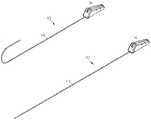
- FIG. 1Ais a perspective view illustrating a deflectable catheter assembly constructed in accordance with one embodiment.
- FIG. 1Bis a perspective view illustrating a deflectable catheter assembly constructed in accordance with one embodiment.
- FIG. 2is a perspective view illustrating a deflectable catheter body constructed in accordance with one embodiment.
- FIG. 3is a perspective view illustrating a distal portion of the deflectable catheter body constructed in accordance with one embodiment.
- FIG. 4is an end view of the distal end of the deflectable catheter assembly constructed in accordance with one embodiment.
- FIG. 5is an end view of the proximal end of the deflectable catheter assembly constructed in accordance with one embodiment.
- FIG. 6is a cross-sectional view illustrating a portion of the deflectable catheter assembly constructed in accordance with one embodiment.
- FIG. 7is a side view illustrating a portion of a catheter body constructed in accordance with another embodiment.
- FIG. 8is a cross-sectional view illustrating a distal end portion of a catheter body constructed in accordance with another embodiment.
- FIG. 9is a perspective view illustrating a proximal end portion of a catheter body constructed in accordance with one embodiment.
- FIGS. 1A and 1Billustrate a deflectable catheter assembly 100 , where FIG. 1A illustrates the deflectable catheter assembly 100 in an articulated position, and FIG. 1B illustrates the deflectable catheter assembly 100 in an unarticulated position.
- the deflectable catheter assembly 100includes a deflectable catheter body 110 and a handle assembly 150 that houses steering mechanisms for deflection of the catheter body 110 .
- the handle assembly 150allows for the deflection of a distal end of the catheter body 110 .
- One example of the handle assembly 150is described in co-pending application Ser. No. 10/179,633, assigned to Enpath Medical, Inc., and is entitled “Articulating Handle For a Deflectable Catheter,” which is incorporated herein by reference.
- the pull wire 120is connected to an actuator that is slid or rotated to apply tension to the pull wire 120 .
- the pull wire anchor at the distal end of the catheter body 110is pulled causing the distal portion of the catheter body 110 to curve in a predetermined direction or directions.
- the catheter body 110comprises an elongate tubular construction that is flexible yet substantially non-compressible along its length.
- the deflectable catheter body 110extends from a proximal end 102 to a distal end 104 , where the distal end 104 is disposed within a patient.
- a proximal tip 103At the proximal end 102 is a proximal tip 103 , and at the distal end 104 is a distal tip 105 .
- the physiciancontrols the deflection of the deflectable catheter body 110 with the handle assembly 150 ( FIGS. 1A and 1B ) and a pull wire 120 ( FIG. 3 ), as further described below.
- the distal end 104is deflected to traverse various branch vessels with the catheter assembly 100 ( FIG. 1 ).
- FIG. 3illustrates a partial cut-away view of FIG. 2 , including the distal end 104 of the catheter body 110 .
- the catheter body 110includes a pull wire anchor 121 that is secured to the catheter body 110 .
- the pull wire 120is secured to the pull wire anchor 121 , for example, as described in co-pending U.S. Provisional Patent Application entitled “Pull Wire Anchor For A Removable Medical Device And A Method Therefor,” assigned to Enpath Medical, Inc., and having Ser. No. 60/409,494, which is incorporated herein by reference. It should be noted that the pull wire can be secured to the distal end 104 of the catheter body 110 in other manners.
- the pull wire anchor 121in one option, comprises a marker band 119 that is viewable, for example, under fluoroscopy.
- the catheter body 110includes a stiffening member embedded therein, such as a braided stainless steel member 111 .
- the stiffening memberfacilitates rotation of the distal end 104 from the proximal end 102 , and also assists in preventing the catheter body 110 from collapsing.
- FIG. 4illustrates an end-view of the catheter body 110 at its, distal end 104 ( FIG. 2 ).
- the catheter body 110is further defined by an outer shaft surface 112 .
- Disposed within the deflectable catheter body 110includes at least one delivery lumen 130 that extends from the proximal end through the catheter body distal end 104 .
- the delivery lumen 130is lined with liner material 132 , for example, PTFE. The lining of the delivery lumen 130 allows for instruments to be more easily inserted therethrough.
- the delivery lumen 130provides a passage from the controlling end to the distal end, such that a physician can insert a device or fluid in at the proximal end and it will travel through the catheter body 110 to the distal end 104 ( FIG. 2 ), where it will exit the catheter body 110 .
- the deflectable nature, of the body 110in conjunction with the steering assembly, allows for a physician to direct the application of a device and/or medicine or fluid to a particular location within a patient.
- the delivery lumen 130is configured to receive a variety of medical devices 134 therethrough.
- suitable devicesinclude, but are not limited to, leads, stents, dilators, guidewires, EP mapping catheters, ablation devices, etc.
- fluids and/or medicinecan be distributed and targeted to a certain location using the deflectable catheter assembly 100 ( FIG. 1A ).
- the deflectable catheter assembly 100( FIG. 1A ) further includes a pull wire 120 associated therewith, where the pull wire 120 is received within an actuator lumen 122 .
- the actuator lumen 122is disposed within the catheter body 110 , and the pull wire 120 is movably disposed within the actuator lumen 122 .
- the actuator lumen 122extends from a location near or at the distal end 104 (see FIG. 3 ) to an intermediate location that does not extend through the proximal end 102 (see FIG. 2 ).
- the actuator lumen 122terminates at a location in a side wall 124 of the catheter body 110 .
- FIG. 5illustrates an end view of the catheter body 110 at the proximal end.
- the lumen 122does not extend to the proximal end nor to the proximal tip of the catheter body 110 . Therefore, there is no cross-contamination of fluids or gasses from the delivery lumen 130 to the actuator lumen 122 , or vice versa.
- the actuator lumen 122further includes an actuator lumen liner 126 therein.
- the actuator lumen liner 126forms a lumen therein, where the lumen receives the pull wire 120 therein.
- the actuator lumen liner 126is formed of PTFE in one option.
- Other suitable materials for the actuator lumen liner 126include, but are not limited to, FEP or polyether-block-amide.
- the actuator lumen liner 126further includes a stiffening member such as braided material.
- the braided materialassists in preventing the actuator lumen liner 126 from collapsing when the actuator lumen liner 126 is pulled out a side lumen, as further described below.
- the actuator lumen liner 126extends from a location 131 near the distal end 104 .
- the distal end 127 of the actuator lumen liner 126is spaced away from the anchor 121 a distance “d”. This allows for improved manufacturability of the catheter body 110 assembly. For instance, if the pull wire is not perfectly aligned with the pull wire anchor 121 , this can result in irregularities in the outer diameter if the actuator lumen liner 126 extends up to the anchor 121 .
- the actuator lumen liner 126extends along the catheter body 110 to a location near the proximal end 102 , as shown in FIG. 6 .
- the actuator liner 126exits through a side wall 124 of the catheter body 110 at 129 .
- the actuator lumen liner 126is pulled through the side wall 124 of the catheter body 110 through an exit lumen 128 of the catheter body 110 .
- the actuator lumen liner 126does not continue within the catheter body 110 through the proximal end 102 , and does not continue through the proximal tip of the catheter body 110 .
- the actuator lumen liner 126assists in sealing the proximal end of the catheter body 110 , which prevents fluids exiting or co-mingling at the proximal end of the catheter body 110 .
- a sealis formed around the actuator lumen liner 126 with material 188 reflowed around a portion of the actuator lumen liner 126 .
- FIG. 7illustrates another option for the catheter body 110 ′.
- the catheter body 110 ′includes at least a first segment 150 and a second segment 152 .
- the first segment 150has a different durometer than the second segment 152 .
- the first segment 150is formed separate from the second segment, and the first segment includes a delivery lumen and an actuator lumen therein, as discussed above.
- the second segment 152includes a delivery lumen, as discussed above. However, there are no lumens in the second segment 152 which are coupled with the actuator lumen.
- the second segment 152forms the proximal end of the catheter body 110 ′, and the first segment 150 forms the intermediate portion of the catheter body 110 ′.
- a third segment having a different structureforms the distal end of the catheter body 110 ′. It should be noted that more segments are further options.
- the catheter body 110 ′includes a notch 160 in the second segment 152 at a location 154 adjacent the first segment 150 .
- the notch 160allows for the actuator lumen liner (discussed above) to transition and exit more easily from an interior portion of the first segment 150 , where the lumen and/or the liner do not extend through the proximal end surface of the catheter body 110 ′. The stress on the actuator lumen liner is reduced, and a smoother transition occurs.
- the delivery lumen lineris placed over a mandrel, and the actuator lumen liner is threaded over the pull wire and placed over the delivery lumen liner.
- the pull wire anchoris placed over the delivery lumen liner and coupled with the pull wire.
- Stiffening materialis optionally placed over the delivery lumen liner and the actuator lumen liner.
- Outer tubingis placed over the delivery lumen liner, which will form the outer surface of the catheter body.
- the itemsare held together, for example, by placing shrink tubing thereover and heating the shrink tubing.
- the itemsare reflowed together, a process which blends the material of the outer tubing, actuator lumen liner, and the delivery lumen liner.
- the shrink tubingis removed from the assembly.
- an outer jacketis slid over a proximal end of the delivery lumen liner, but not over the actuator lumen liner.
- the outer jacketabuts the first outer jacket discussed above, and the items are secured together, for example, by heat shrink tubing. These elements are reflowed together, and the shrink tubing is removed.
- the deflectable catheter body assemblyis coupled with a handle assembly with a steering mechanism to form the deflectable catheter assembly.
- the catheter assembly 100 ′′further includes an accessory lumen 190 .
- the accessory lumen 190is disposed adjacent to the delivery lumen 130 , and in one option, the accessory lumen 190 has a substantially smaller diameter than the delivery lumen 130 .
- the delivery lumen 130extends from a location in the distal end surface 170 through the proximal tip 172 .
- the accessory lumen 190extends from a location, in one option, in the distal tip 170 to a location 180 not in the proximal tip 172 , for example, terminating at a location on the side wall 124 of the catheter body 110 .
- a liner 192is disposed within the accessory lumen 190 .
- the liner 192includes, but is not limited to, the materials discussed above for the actuator lumen.
- a stiffening membersuch as a braided member, is disposed adjacent to, or surrounding the accessory lumen 190 , which assists in preventing the accessory lumen 190 from collapsing.
- the accessory lumen 190is sized to receive therein accessories 194 .
- a fiber optic instrumentis disposed within the accessory lumen 190 .
- the fiber optic instrumentcan be used to assist in directing the distal end of the catheter body 110 within the patient. This allows for a reduction or elimination of radiation exposure, for example, radiation exposure that occurs during fluoroscopic procedures.
- Other types of instrumentscan be disposed in the accessory lumen 190 as well, for example, an instrument 194 can includes one or more sensors 196 thereon.
- the delivery lumen lineris placed over a mandrel, and the optional actuator lumen liner is optionally threaded over the pull wire and placed over the delivery lumen liner.
- the pull wire anchoris placed over the delivery lumen liner and coupled with the pull wire.
- An instrumentsuch as an instrument with a sensor or an instrument such as a fiber optic instrument is placed over the delivery lumen liner.
- Stiffening materialis optionally placed over the delivery lumen liner, the actuator lumen liner, and the instrument.
- Outer tubingis placed over the delivery lumen liner, the optional actuator lumen liner, and the instrument, which will form the outer surface of the catheter body.
- the itemsare held together, for example, by placing shrink tubing thereover and heating the shrink tubing.
- the itemsare reflowed together, a process which blends the material of the outer tubing, actuator lumen liner, the instrument, and the delivery lumen liner.
- the shrink tubingis removed from the assembly.
- an outer jacketis slid over a proximal end of the delivery lumen liner, but not over the actuator lumen liner nor the instrument.
- the outer jacketabuts the first outer jacket discussed above, and the items are secured together, for example, by heat shrink tubing. These elements are reflowed together, and the shrink tubing is removed.
- the deflectable catheter body assemblyis coupled with a handle assembly with a steering mechanism to form the deflectable catheter assembly.
- the deflectable catheter assemblyprovides a catheter assembly that is easy to use and manipulate, and does not interfere with the physician's ability to manipulate the deflectable catheter assembly. Furthermore, the catheter assembly design assists in preventing leakage from the actuator lumen and/or the accessory lumen. The catheter assembly further prevents co-mingling of fluids from the delivery lumen to the actuator lumen and/or the accessory lumen, and prevents fluids from entering the actuator lumen and/or the accessory lumen.
- the accessory lumen and/or the accessory lumenprovide for more flexibility during implant procedures, and provides for more options with the catheter assembly.
Landscapes
- Health & Medical Sciences (AREA)
- Life Sciences & Earth Sciences (AREA)
- Engineering & Computer Science (AREA)
- Heart & Thoracic Surgery (AREA)
- Biophysics (AREA)
- Pulmonology (AREA)
- Anesthesiology (AREA)
- Biomedical Technology (AREA)
- Mechanical Engineering (AREA)
- Hematology (AREA)
- Animal Behavior & Ethology (AREA)
- General Health & Medical Sciences (AREA)
- Public Health (AREA)
- Veterinary Medicine (AREA)
- Media Introduction/Drainage Providing Device (AREA)
- External Artificial Organs (AREA)
Abstract
Description
Claims (14)
Priority Applications (8)
| Application Number | Priority Date | Filing Date | Title |
|---|---|---|---|
| US10/179,124US7029468B2 (en) | 2002-06-25 | 2002-06-25 | Catheter assembly with side wall exit lumen and method therefor |
| EP03739273AEP1515771B1 (en) | 2002-06-25 | 2003-06-25 | Catheter assembly with side wall exit and method of manufacture |
| AU2003245646AAU2003245646A1 (en) | 2002-06-25 | 2003-06-25 | Catheter assembly with side wall exit lumen and method therefor |
| DE60315833TDE60315833T2 (en) | 2002-06-25 | 2003-06-25 | Catheter with side wall lumen exit and manufacturing process |
| AT03739273TATE370761T1 (en) | 2002-06-25 | 2003-06-25 | CATHETER WITH SIDE WALL LUMEN EXIT AND METHOD OF MANUFACTURING |
| CA2489546ACA2489546C (en) | 2002-06-25 | 2003-06-25 | Catheter assembly with side wall exit lumen and method therefor |
| PCT/US2003/019768WO2004000404A1 (en) | 2002-06-25 | 2003-06-25 | Catheter assembly with side wall exit lumen and method therefor |
| US11/385,308US8206344B2 (en) | 2002-06-25 | 2006-03-21 | Catheter assembly with side wall exit lumen and method therefor |
Applications Claiming Priority (1)
| Application Number | Priority Date | Filing Date | Title |
|---|---|---|---|
| US10/179,124US7029468B2 (en) | 2002-06-25 | 2002-06-25 | Catheter assembly with side wall exit lumen and method therefor |
Related Child Applications (1)
| Application Number | Title | Priority Date | Filing Date |
|---|---|---|---|
| US11/385,308DivisionUS8206344B2 (en) | 2002-06-25 | 2006-03-21 | Catheter assembly with side wall exit lumen and method therefor |
Publications (2)
| Publication Number | Publication Date |
|---|---|
| US20030236492A1 US20030236492A1 (en) | 2003-12-25 |
| US7029468B2true US7029468B2 (en) | 2006-04-18 |
Family
ID=29734860
Family Applications (2)
| Application Number | Title | Priority Date | Filing Date |
|---|---|---|---|
| US10/179,124Expired - LifetimeUS7029468B2 (en) | 2002-06-25 | 2002-06-25 | Catheter assembly with side wall exit lumen and method therefor |
| US11/385,308Expired - LifetimeUS8206344B2 (en) | 2002-06-25 | 2006-03-21 | Catheter assembly with side wall exit lumen and method therefor |
Family Applications After (1)
| Application Number | Title | Priority Date | Filing Date |
|---|---|---|---|
| US11/385,308Expired - LifetimeUS8206344B2 (en) | 2002-06-25 | 2006-03-21 | Catheter assembly with side wall exit lumen and method therefor |
Country Status (7)
| Country | Link |
|---|---|
| US (2) | US7029468B2 (en) |
| EP (1) | EP1515771B1 (en) |
| AT (1) | ATE370761T1 (en) |
| AU (1) | AU2003245646A1 (en) |
| CA (1) | CA2489546C (en) |
| DE (1) | DE60315833T2 (en) |
| WO (1) | WO2004000404A1 (en) |
Cited By (31)
| Publication number | Priority date | Publication date | Assignee | Title |
|---|---|---|---|---|
| US20050140068A1 (en)* | 2003-12-10 | 2005-06-30 | William A. Cook Australia Pty. Ltd. | Injection moulding of functional cavities |
| US20060184108A1 (en)* | 2002-06-25 | 2006-08-17 | Enpath Medical, Inc. | Catheter assembly with side wall exit lumen and method therefor |
| US20060260098A1 (en)* | 2005-05-18 | 2006-11-23 | Brown Michelle J | Weight for Hand-Held Tools Such as Writing Instruments |
| US20070173757A1 (en)* | 2003-10-01 | 2007-07-26 | Marc-Alan Levine | Long nose manipulatable catheter |
| US20090105816A1 (en)* | 2007-10-19 | 2009-04-23 | Olsen Daniel H | System using a helical retainer in the direct plication annuloplasty treatment of mitral valve regurgitation |
| US20090131886A1 (en)* | 2007-11-16 | 2009-05-21 | Liu Y King | Steerable vertebroplasty system |
| US20100076408A1 (en)* | 2007-10-19 | 2010-03-25 | Matthew Krever | Deflecting guide catheter for use in a minimally invasive medical procedure for the treatment of mitral valve regurgitation |
| US20100145309A1 (en)* | 2008-12-03 | 2010-06-10 | C. R. Bard, Inc. | Retractable catheter |
| US20100160719A1 (en)* | 2006-06-30 | 2010-06-24 | Kassab Ghassan S | Devices, systems, and methods for pericardial access |
| US20100168791A1 (en)* | 2006-06-30 | 2010-07-01 | Cvdevices, Llc (A California Limited Liability Company) | Systems and methods for closing a hole in cardiac tissue |
| US20100185140A1 (en)* | 2006-06-30 | 2010-07-22 | Kassab Ghassan S | Devices, systems, and methods for promotion of infarct healing and reinforcement of border zone |
| US20100228221A1 (en)* | 2006-06-30 | 2010-09-09 | Kassab Ghassan S | Devices, systems, and methods for obtaining biopsy tissue samples |
| US20100312256A1 (en)* | 2006-06-30 | 2010-12-09 | Cvdevices, Llc | Devices, systems, and methods for lead delivery |
| US20110060182A1 (en)* | 2007-04-27 | 2011-03-10 | Cvdevices, Llc | Systems for engaging a bodily tissue and methods of using the same |
| US20110092955A1 (en)* | 2009-10-07 | 2011-04-21 | Purdy Phillip D | Pressure-Sensing Medical Devices, Systems and Methods, and Methods of Forming Medical Devices |
| US20110144572A1 (en)* | 2007-04-27 | 2011-06-16 | Kassab Ghassan S | Steering engagement catheter devices, systems, and methods |
| US20110224720A1 (en)* | 2010-03-11 | 2011-09-15 | Cvdevices, Llc | Devices, systems, and methods for closing a hole in cardiac tissue |
| US20120053569A1 (en)* | 2005-06-09 | 2012-03-01 | Greatbatch Ltd. | Push/Pull Wire Anchor |
| US8540674B2 (en) | 2007-04-27 | 2013-09-24 | Cvdevices, Llc | Devices, systems, and methods for transeptal atrial puncture using an engagement catheter platform |
| US8827981B2 (en) | 2007-11-16 | 2014-09-09 | Osseon Llc | Steerable vertebroplasty system with cavity creation element |
| US9510885B2 (en) | 2007-11-16 | 2016-12-06 | Osseon Llc | Steerable and curvable cavity creation system |
| US20170007750A1 (en)* | 2012-04-05 | 2017-01-12 | Brady Woolford | In-joint sensor for a surgical fluid management pump system |
| US10315013B2 (en) | 2001-07-13 | 2019-06-11 | Endophys Holdings, Llc | Sheath with sensing capabilities |
| US10463380B2 (en) | 2016-12-09 | 2019-11-05 | Dfine, Inc. | Medical devices for treating hard tissues and related methods |
| US10478241B2 (en) | 2016-10-27 | 2019-11-19 | Merit Medical Systems, Inc. | Articulating osteotome with cement delivery channel |
| US10624652B2 (en) | 2010-04-29 | 2020-04-21 | Dfine, Inc. | System for use in treatment of vertebral fractures |
| US10660656B2 (en) | 2017-01-06 | 2020-05-26 | Dfine, Inc. | Osteotome with a distal portion for simultaneous advancement and articulation |
| US11026744B2 (en) | 2016-11-28 | 2021-06-08 | Dfine, Inc. | Tumor ablation devices and related methods |
| US11197681B2 (en) | 2009-05-20 | 2021-12-14 | Merit Medical Systems, Inc. | Steerable curvable vertebroplasty drill |
| US11510723B2 (en) | 2018-11-08 | 2022-11-29 | Dfine, Inc. | Tumor ablation device and related systems and methods |
| US11986229B2 (en) | 2019-09-18 | 2024-05-21 | Merit Medical Systems, Inc. | Osteotome with inflatable portion and multiwire articulation |
Families Citing this family (17)
| Publication number | Priority date | Publication date | Assignee | Title |
|---|---|---|---|---|
| US6482221B1 (en)* | 2000-08-21 | 2002-11-19 | Counter Clockwise, Inc. | Manipulatable delivery catheter for occlusive devices (II) |
| US6945956B2 (en)* | 2002-12-23 | 2005-09-20 | Medtronic, Inc. | Steerable catheter |
| US7591813B2 (en) | 2003-10-01 | 2009-09-22 | Micrus Endovascular Corporation | Long nose manipulatable catheter |
| US7678081B2 (en)* | 2004-07-12 | 2010-03-16 | Pacesetter, Inc. | Methods and devices for transseptal access |
| US8029470B2 (en) | 2004-09-30 | 2011-10-04 | Pacesetter, Inc. | Transmembrane access systems and methods |
| US20060079787A1 (en)* | 2004-09-30 | 2006-04-13 | Whiting James S | Transmembrane access systems and methods |
| US20060259009A1 (en)* | 2005-05-12 | 2006-11-16 | Medtronic Vascular, Inc. | Guidewire loader for bifurcated vessel |
| US7914515B2 (en) | 2007-07-18 | 2011-03-29 | St. Jude Medical, Atrial Fibrillation Division, Inc. | Catheter and introducer catheter having torque transfer layer and method of manufacture |
| US8122594B2 (en)* | 2007-12-31 | 2012-02-28 | St. Jude Medical, Atrial Fibrillation Division, Inc. | Method of manufacturing a deflectable electrophysiological catheter |
| EP2994185B1 (en) | 2013-05-07 | 2017-10-18 | St. Jude Medical Atrial Fibrillation Division Inc. | Guiding medical devices and associated methods of manufacturing |
| WO2017147493A1 (en) | 2016-02-24 | 2017-08-31 | Incept, Llc | Enhanced flexibility neurovascular catheter |
| AU2019262972B2 (en) | 2018-05-01 | 2025-02-27 | Incept, Llc | Devices and methods for removing obstructive material from an intravascular site |
| US11766539B2 (en) | 2019-03-29 | 2023-09-26 | Incept, Llc | Enhanced flexibility neurovascular catheter |
| US20230248502A1 (en) | 2019-12-18 | 2023-08-10 | Imperative Care, Inc. | Sterile field clot capture module for use in thrombectomy system |
| EP4076611A4 (en) | 2019-12-18 | 2023-11-15 | Imperative Care, Inc. | Methods and systems for treating venous thromboembolic disease |
| JP2025506685A (en)* | 2022-02-16 | 2025-03-13 | インパラティブ、ケア、インク. | Catheters with preset curves |
| US12171917B1 (en) | 2024-01-08 | 2024-12-24 | Imperative Care, Inc. | Devices for blood capture and reintroduction during aspiration procedure |
Citations (16)
| Publication number | Priority date | Publication date | Assignee | Title |
|---|---|---|---|---|
| US4033331A (en)* | 1975-07-17 | 1977-07-05 | Guss Stephen B | Cardiac catheter and method of using same |
| US4149535A (en)* | 1976-05-06 | 1979-04-17 | Gist-Brocades N.V. | Catheter holding device |
| US4898577A (en) | 1988-09-28 | 1990-02-06 | Advanced Cardiovascular Systems, Inc. | Guiding cathether with controllable distal tip |
| US5219335A (en)* | 1991-05-23 | 1993-06-15 | Scimed Life Systems, Inc. | Intravascular device such as introducer sheath or balloon catheter or the like and methods for use thereof |
| US5391146A (en) | 1993-06-24 | 1995-02-21 | Conceptus, Inc. | Mechanism for manipulating the distal end of a biomedical device |
| US5429604A (en) | 1992-03-18 | 1995-07-04 | Spectranetics Corporation | Fiber optic catheter with twistable tip |
| US5642736A (en) | 1992-02-14 | 1997-07-01 | Avitall; Boaz | Biplanar deflectable catheter for arrhythmogenic tissue ablation |
| US5964757A (en) | 1997-09-05 | 1999-10-12 | Cordis Webster, Inc. | Steerable direct myocardial revascularization catheter |
| US6171277B1 (en) | 1997-12-01 | 2001-01-09 | Cordis Webster, Inc. | Bi-directional control handle for steerable catheter |
| US6251092B1 (en) | 1997-12-30 | 2001-06-26 | Medtronic, Inc. | Deflectable guiding catheter |
| US6273879B1 (en)* | 1990-08-28 | 2001-08-14 | Scimed Life Systems Inc | Balloon catheter with distal guide wire lumen |
| US6309379B1 (en)* | 1991-05-23 | 2001-10-30 | Lloyd K. Willard | Sheath for selective delivery of multiple intravascular devices and methods of use thereof |
| US20010049491A1 (en) | 2000-04-24 | 2001-12-06 | Biotran Corporation, Inc | Process for producing steerable sheath catheters |
| WO2002015972A2 (en) | 2000-08-21 | 2002-02-28 | Counter Clockwise, Inc. | Manipulatable delivery catheter for occlusive devices |
| US6485457B1 (en)* | 1999-09-28 | 2002-11-26 | Terumo Kabushiki Kaisha | Catheter |
| US6746442B2 (en)* | 1996-09-13 | 2004-06-08 | Boston Scientific Corporation | Single operator exchange biliary catheter |
Family Cites Families (16)
| Publication number | Priority date | Publication date | Assignee | Title |
|---|---|---|---|---|
| US2688329A (en)* | 1953-03-19 | 1954-09-07 | American Cystoscope Makers Inc | Catheter |
| US4416865A (en) | 1973-02-20 | 1983-11-22 | Research Corporation | Radiopharmaceuticals for localization of thromboembolic disease |
| US4385046A (en) | 1980-12-15 | 1983-05-24 | Minnesota Mining And Manufacturing Company | Diagnostic radio-labeled polysaccharide derivatives |
| US5066788A (en) | 1984-09-21 | 1991-11-19 | Boehringer Ingelheim International Gmbh | Blood coagulation inhibiting proteins, processes for preparing them and their uses |
| NO164991C (en) | 1984-09-21 | 1990-12-05 | Boehringer Ingelheim Int | PROCEDURE FOR THE PREPARATION OF BLOOD-COAGULATING INHIBITIVE PROTEINS. |
| US4659839A (en) | 1984-10-10 | 1987-04-21 | Mallinckrodt, Inc. | Coupling agents for radiolabeled antibody fragments |
| US4820505A (en) | 1985-04-04 | 1989-04-11 | Scripps Clinic And Research Foundation | Detection of activated platelets with antibodies to thrombospondin |
| US4920980A (en)* | 1987-09-14 | 1990-05-01 | Cordis Corporation | Catheter with controllable tip |
| US4998917A (en)* | 1988-05-26 | 1991-03-12 | Advanced Cardiovascular Systems, Inc. | High torque steerable dilatation catheter |
| US5118610A (en) | 1989-11-30 | 1992-06-02 | Board Of Regents, The University Of Texas System | Techniques for detecting insect contamination of foodstuffs |
| DE4320962C2 (en)* | 1993-06-24 | 1997-04-17 | Osypka Peter | Catheter made of a flexible plastic tube |
| US5454794A (en)* | 1993-10-15 | 1995-10-03 | Pdt Systems, Inc. | Steerable light diffusing catheter |
| US6280433B1 (en)* | 1999-09-09 | 2001-08-28 | Medtronic, Inc. | Introducer system |
| US6955657B1 (en)* | 2001-12-31 | 2005-10-18 | Advanced Cardiovascular Systems, Inc. | Intra-ventricular substance delivery catheter system |
| US7029468B2 (en) | 2002-06-25 | 2006-04-18 | Enpath Medical, Inc. | Catheter assembly with side wall exit lumen and method therefor |
| US7131963B1 (en)* | 2002-06-27 | 2006-11-07 | Advanced Cardiovascular Systems, Inc. | Catheters and methods of using catheters |
- 2002
- 2002-06-25USUS10/179,124patent/US7029468B2/ennot_activeExpired - Lifetime
- 2003
- 2003-06-25DEDE60315833Tpatent/DE60315833T2/ennot_activeExpired - Lifetime
- 2003-06-25WOPCT/US2003/019768patent/WO2004000404A1/enactiveIP Right Grant
- 2003-06-25EPEP03739273Apatent/EP1515771B1/ennot_activeExpired - Lifetime
- 2003-06-25CACA2489546Apatent/CA2489546C/ennot_activeExpired - Lifetime
- 2003-06-25ATAT03739273Tpatent/ATE370761T1/ennot_activeIP Right Cessation
- 2003-06-25AUAU2003245646Apatent/AU2003245646A1/ennot_activeAbandoned
- 2006
- 2006-03-21USUS11/385,308patent/US8206344B2/ennot_activeExpired - Lifetime
Patent Citations (16)
| Publication number | Priority date | Publication date | Assignee | Title |
|---|---|---|---|---|
| US4033331A (en)* | 1975-07-17 | 1977-07-05 | Guss Stephen B | Cardiac catheter and method of using same |
| US4149535A (en)* | 1976-05-06 | 1979-04-17 | Gist-Brocades N.V. | Catheter holding device |
| US4898577A (en) | 1988-09-28 | 1990-02-06 | Advanced Cardiovascular Systems, Inc. | Guiding cathether with controllable distal tip |
| US6273879B1 (en)* | 1990-08-28 | 2001-08-14 | Scimed Life Systems Inc | Balloon catheter with distal guide wire lumen |
| US6309379B1 (en)* | 1991-05-23 | 2001-10-30 | Lloyd K. Willard | Sheath for selective delivery of multiple intravascular devices and methods of use thereof |
| US5219335A (en)* | 1991-05-23 | 1993-06-15 | Scimed Life Systems, Inc. | Intravascular device such as introducer sheath or balloon catheter or the like and methods for use thereof |
| US5642736A (en) | 1992-02-14 | 1997-07-01 | Avitall; Boaz | Biplanar deflectable catheter for arrhythmogenic tissue ablation |
| US5429604A (en) | 1992-03-18 | 1995-07-04 | Spectranetics Corporation | Fiber optic catheter with twistable tip |
| US5391146A (en) | 1993-06-24 | 1995-02-21 | Conceptus, Inc. | Mechanism for manipulating the distal end of a biomedical device |
| US6746442B2 (en)* | 1996-09-13 | 2004-06-08 | Boston Scientific Corporation | Single operator exchange biliary catheter |
| US5964757A (en) | 1997-09-05 | 1999-10-12 | Cordis Webster, Inc. | Steerable direct myocardial revascularization catheter |
| US6171277B1 (en) | 1997-12-01 | 2001-01-09 | Cordis Webster, Inc. | Bi-directional control handle for steerable catheter |
| US6251092B1 (en) | 1997-12-30 | 2001-06-26 | Medtronic, Inc. | Deflectable guiding catheter |
| US6485457B1 (en)* | 1999-09-28 | 2002-11-26 | Terumo Kabushiki Kaisha | Catheter |
| US20010049491A1 (en) | 2000-04-24 | 2001-12-06 | Biotran Corporation, Inc | Process for producing steerable sheath catheters |
| WO2002015972A2 (en) | 2000-08-21 | 2002-02-28 | Counter Clockwise, Inc. | Manipulatable delivery catheter for occlusive devices |
Cited By (85)
| Publication number | Priority date | Publication date | Assignee | Title |
|---|---|---|---|---|
| US10716921B2 (en) | 2001-07-13 | 2020-07-21 | Endophys Holdings, Llc | Methods of using a dual-lumen sheath in intraluminal procedures |
| US10315013B2 (en) | 2001-07-13 | 2019-06-11 | Endophys Holdings, Llc | Sheath with sensing capabilities |
| US8206344B2 (en) | 2002-06-25 | 2012-06-26 | Greatbatch Ltd. | Catheter assembly with side wall exit lumen and method therefor |
| US20060184108A1 (en)* | 2002-06-25 | 2006-08-17 | Enpath Medical, Inc. | Catheter assembly with side wall exit lumen and method therefor |
| US20070173757A1 (en)* | 2003-10-01 | 2007-07-26 | Marc-Alan Levine | Long nose manipulatable catheter |
| US8414524B2 (en) | 2003-10-01 | 2013-04-09 | Micrus Endovascular Corporation | Long nose manipulatable catheter |
| US7455806B2 (en)* | 2003-12-10 | 2008-11-25 | William A. Cook Australia Pty. Ltd. | Injection moulding of functional cavities |
| US20050140068A1 (en)* | 2003-12-10 | 2005-06-30 | William A. Cook Australia Pty. Ltd. | Injection moulding of functional cavities |
| US20060260098A1 (en)* | 2005-05-18 | 2006-11-23 | Brown Michelle J | Weight for Hand-Held Tools Such as Writing Instruments |
| US8540697B2 (en)* | 2005-06-09 | 2013-09-24 | Greatbatch Ltd. | Push/pull wire anchor |
| US20120053569A1 (en)* | 2005-06-09 | 2012-03-01 | Greatbatch Ltd. | Push/Pull Wire Anchor |
| US8876776B2 (en) | 2006-06-30 | 2014-11-04 | Cvdevices, Llc | Engagement catheter systems and devices and methods of using the same |
| US20100228221A1 (en)* | 2006-06-30 | 2010-09-09 | Kassab Ghassan S | Devices, systems, and methods for obtaining biopsy tissue samples |
| US9393383B2 (en)* | 2006-06-30 | 2016-07-19 | Cvdevices, Llc | Intravascular catheters, systems, and methods |
| US9295768B2 (en) | 2006-06-30 | 2016-03-29 | Cvdevices, Llc | Devices and methods for assisting cardiac function |
| US20150231374A1 (en)* | 2006-06-30 | 2015-08-20 | Cvdevices, Llc | Intravascular catheters, systems, and methods |
| US20100185044A1 (en)* | 2006-06-30 | 2010-07-22 | Cvdevices, Llc (A California Limited Liability Company) | Devices and methods for assisting heart function |
| US20100185140A1 (en)* | 2006-06-30 | 2010-07-22 | Kassab Ghassan S | Devices, systems, and methods for promotion of infarct healing and reinforcement of border zone |
| US20100312256A1 (en)* | 2006-06-30 | 2010-12-09 | Cvdevices, Llc | Devices, systems, and methods for lead delivery |
| US20100160719A1 (en)* | 2006-06-30 | 2010-06-24 | Kassab Ghassan S | Devices, systems, and methods for pericardial access |
| US20100256599A1 (en)* | 2006-06-30 | 2010-10-07 | Cvdevices, Llc | Devices, systems, and methods for accessing cardiac tissue |
| US20100168655A1 (en)* | 2006-06-30 | 2010-07-01 | Cvdevices, Llc | Devices, systems, and methods for removing fluid from a bodily tissue |
| US8894606B2 (en) | 2006-06-30 | 2014-11-25 | Cvdevices, Llc | Devices, systems, and methods for accessing cardiac tissue |
| US9023075B2 (en) | 2006-06-30 | 2015-05-05 | Cvdevices, Llc | Devices, systems, and methods for lead delivery |
| US9907954B2 (en) | 2006-06-30 | 2018-03-06 | Cvdevices, Llc | Devices and systems for accessing cardiac tissue |
| US11191955B2 (en) | 2006-06-30 | 2021-12-07 | Cvdevices, Llc | Devices and systems for accessing cardiac tissue |
| US20110130744A1 (en)* | 2006-06-30 | 2011-06-02 | Cvdevices, Llc | Devices, systems, and methods for accessing the epicardial surface of the heart |
| US8328752B2 (en) | 2006-06-30 | 2012-12-11 | Cvdevices, Llc | Devices, systems, and methods for promotion of infarct healing and reinforcement of border zone |
| US8303481B2 (en) | 2006-06-30 | 2012-11-06 | Cvdevices, Llc | Devices and methods for assisting heart function |
| US8075532B2 (en) | 2006-06-30 | 2011-12-13 | Cvdevices, Llc | Devices, systems, and methods for pericardial access |
| US8211084B2 (en) | 2006-06-30 | 2012-07-03 | Cvdevices, Llc | Devices, systems, and methods for accessing the epicardial surface of the heart |
| US20100168791A1 (en)* | 2006-06-30 | 2010-07-01 | Cvdevices, Llc (A California Limited Liability Company) | Systems and methods for closing a hole in cardiac tissue |
| US8128593B2 (en) | 2006-06-30 | 2012-03-06 | Cvdevices, Llc | Removing fluid from a bodily tissue via a catheter with circumferential concave grooves |
| US8147424B2 (en) | 2006-06-30 | 2012-04-03 | Cvdevices, Llc | Devices, systems, and methods for obtaining biopsy tissue samples |
| US9955999B2 (en) | 2007-04-27 | 2018-05-01 | Cvdevices, Llc | Systems, devices, and methods for transeptal atrial puncture using an engagement catheter platform |
| US20110060182A1 (en)* | 2007-04-27 | 2011-03-10 | Cvdevices, Llc | Systems for engaging a bodily tissue and methods of using the same |
| US8105309B2 (en) | 2007-04-27 | 2012-01-31 | Cvdevices, Llc | Devices, systems, and methods for myocardial infarct border zone reinforcement |
| US20100168651A1 (en)* | 2007-04-27 | 2010-07-01 | Cvdevices, Llc | Devices, systems, and methods for myocardial infarct border zone reinforcement |
| US20100185141A1 (en)* | 2007-04-27 | 2010-07-22 | CVDeices, LLC (a California limited liability company) | Devices and methods for securing a catheter within a heart |
| US20110144572A1 (en)* | 2007-04-27 | 2011-06-16 | Kassab Ghassan S | Steering engagement catheter devices, systems, and methods |
| US8382699B2 (en) | 2007-04-27 | 2013-02-26 | Cvdevices, Llc | Devices and methods for securing a catheter within a heart |
| US8382651B2 (en) | 2007-04-27 | 2013-02-26 | Cvdevices, Llc | Devices, systems, and methods to facilitate heart function |
| US11013892B2 (en) | 2007-04-27 | 2021-05-25 | Cvdevices, Llc | Steering engagement catheter devices, systems, and methods |
| US10946127B2 (en) | 2007-04-27 | 2021-03-16 | 3Dt Holdings, Llc | Devices and methods for assisting cardiac function |
| US8540674B2 (en) | 2007-04-27 | 2013-09-24 | Cvdevices, Llc | Devices, systems, and methods for transeptal atrial puncture using an engagement catheter platform |
| US20100168761A1 (en)* | 2007-04-27 | 2010-07-01 | Cvdevices, Llc. (A California Iimited Iiability Company) | Devices for accessing the pericardial space surrounding the heart |
| US9095648B2 (en) | 2007-04-27 | 2015-08-04 | Cvdevices, Llc | Devices, systems, and methods for myocardial infarct border zone reinforcement |
| US9901710B2 (en) | 2007-04-27 | 2018-02-27 | Cvdevices, Llc | Steering engagement catheter devices, systems, and methods |
| US9050064B2 (en) | 2007-04-27 | 2015-06-09 | Cvdevices, Llc | Systems for engaging a bodily tissue and methods of using the same |
| US20100185235A1 (en)* | 2007-04-27 | 2010-07-22 | Cvdevices, Llc | Systems and methods for closing an aperture in a bodily tissue |
| US20100076408A1 (en)* | 2007-10-19 | 2010-03-25 | Matthew Krever | Deflecting guide catheter for use in a minimally invasive medical procedure for the treatment of mitral valve regurgitation |
| US8197464B2 (en)* | 2007-10-19 | 2012-06-12 | Cordis Corporation | Deflecting guide catheter for use in a minimally invasive medical procedure for the treatment of mitral valve regurgitation |
| US20090105815A1 (en)* | 2007-10-19 | 2009-04-23 | Matthew Krever | Push-in retainer system for use in the direct plication annuloplasty treatment of mitral valve regurgitation |
| US20090105816A1 (en)* | 2007-10-19 | 2009-04-23 | Olsen Daniel H | System using a helical retainer in the direct plication annuloplasty treatment of mitral valve regurgitation |
| US8226709B2 (en) | 2007-10-19 | 2012-07-24 | Cordis Corporation | Method and system for plicating tissue in a minimally invasive medical procedure for the treatment of mitral valve regurgitation |
| US7842041B2 (en) | 2007-11-16 | 2010-11-30 | Osseon Therapeutics, Inc. | Steerable vertebroplasty system |
| US7811291B2 (en) | 2007-11-16 | 2010-10-12 | Osseon Therapeutics, Inc. | Closed vertebroplasty bone cement injection system |
| US20090131886A1 (en)* | 2007-11-16 | 2009-05-21 | Liu Y King | Steerable vertebroplasty system |
| US8827981B2 (en) | 2007-11-16 | 2014-09-09 | Osseon Llc | Steerable vertebroplasty system with cavity creation element |
| US9510885B2 (en) | 2007-11-16 | 2016-12-06 | Osseon Llc | Steerable and curvable cavity creation system |
| US8535292B2 (en)* | 2008-12-03 | 2013-09-17 | C. R. Bard, Inc. | Retractable catheter |
| US20100145309A1 (en)* | 2008-12-03 | 2010-06-10 | C. R. Bard, Inc. | Retractable catheter |
| AU2009330182B2 (en)* | 2008-12-22 | 2015-07-09 | Cardinal Health 529, Llc | Deflecting guide catheter for mitral valve treatment |
| US11197681B2 (en) | 2009-05-20 | 2021-12-14 | Merit Medical Systems, Inc. | Steerable curvable vertebroplasty drill |
| US9913959B2 (en) | 2009-10-07 | 2018-03-13 | Endophys Holdings, Llc | Device configured for real-time pressure sensing |
| US9597480B2 (en) | 2009-10-07 | 2017-03-21 | Endophys Holding, LLC | Intraluminal devices and systems |
| US20110092955A1 (en)* | 2009-10-07 | 2011-04-21 | Purdy Phillip D | Pressure-Sensing Medical Devices, Systems and Methods, and Methods of Forming Medical Devices |
| US20110224720A1 (en)* | 2010-03-11 | 2011-09-15 | Cvdevices, Llc | Devices, systems, and methods for closing a hole in cardiac tissue |
| US10624652B2 (en) | 2010-04-29 | 2020-04-21 | Dfine, Inc. | System for use in treatment of vertebral fractures |
| US9962472B2 (en)* | 2012-04-05 | 2018-05-08 | Stryker Corporation | In-joint sensor for a surgical fluid management pump system |
| US20170007750A1 (en)* | 2012-04-05 | 2017-01-12 | Brady Woolford | In-joint sensor for a surgical fluid management pump system |
| US10478241B2 (en) | 2016-10-27 | 2019-11-19 | Merit Medical Systems, Inc. | Articulating osteotome with cement delivery channel |
| US11344350B2 (en) | 2016-10-27 | 2022-05-31 | Dfine, Inc. | Articulating osteotome with cement delivery channel and method of use |
| US11026744B2 (en) | 2016-11-28 | 2021-06-08 | Dfine, Inc. | Tumor ablation devices and related methods |
| US11116570B2 (en) | 2016-11-28 | 2021-09-14 | Dfine, Inc. | Tumor ablation devices and related methods |
| US12011215B2 (en) | 2016-11-28 | 2024-06-18 | Dfine, Inc. | Tumor ablation devices and related methods |
| US12433671B2 (en) | 2016-11-28 | 2025-10-07 | Dfine, Inc. | Tumor ablation devices and related methods |
| US10463380B2 (en) | 2016-12-09 | 2019-11-05 | Dfine, Inc. | Medical devices for treating hard tissues and related methods |
| US10470781B2 (en) | 2016-12-09 | 2019-11-12 | Dfine, Inc. | Medical devices for treating hard tissues and related methods |
| US11540842B2 (en) | 2016-12-09 | 2023-01-03 | Dfine, Inc. | Medical devices for treating hard tissues and related methods |
| US10660656B2 (en) | 2017-01-06 | 2020-05-26 | Dfine, Inc. | Osteotome with a distal portion for simultaneous advancement and articulation |
| US11607230B2 (en) | 2017-01-06 | 2023-03-21 | Dfine, Inc. | Osteotome with a distal portion for simultaneous advancement and articulation |
| US11510723B2 (en) | 2018-11-08 | 2022-11-29 | Dfine, Inc. | Tumor ablation device and related systems and methods |
| US11937864B2 (en) | 2018-11-08 | 2024-03-26 | Dfine, Inc. | Ablation systems with parameter-based modulation and related devices and methods |
| US11986229B2 (en) | 2019-09-18 | 2024-05-21 | Merit Medical Systems, Inc. | Osteotome with inflatable portion and multiwire articulation |
Also Published As
| Publication number | Publication date |
|---|---|
| DE60315833T2 (en) | 2008-05-21 |
| EP1515771A1 (en) | 2005-03-23 |
| CA2489546C (en) | 2010-04-20 |
| CA2489546A1 (en) | 2003-12-31 |
| US8206344B2 (en) | 2012-06-26 |
| US20030236492A1 (en) | 2003-12-25 |
| ATE370761T1 (en) | 2007-09-15 |
| EP1515771B1 (en) | 2007-08-22 |
| AU2003245646A1 (en) | 2004-01-06 |
| US20060184108A1 (en) | 2006-08-17 |
| WO2004000404A1 (en) | 2003-12-31 |
| DE60315833D1 (en) | 2007-10-04 |
Similar Documents
| Publication | Publication Date | Title |
|---|---|---|
| US7029468B2 (en) | Catheter assembly with side wall exit lumen and method therefor | |
| US4960411A (en) | Low profile sterrable soft-tip catheter | |
| JP2933389B2 (en) | Balloon catheter having a guide wire lumen at the distal end | |
| US5456680A (en) | Fiber optic catheter with shortened guide wire lumen | |
| CA2627581C (en) | Steerable catheter devices and methods of articulating catheter devices | |
| US5318526A (en) | Flexible endoscope with hypotube activating wire support | |
| US6475187B1 (en) | Convertible catheter incorporating distal force transfer mechanism | |
| US5114414A (en) | Low profile steerable catheter | |
| EP1457230B1 (en) | Catheter | |
| EP0823261B1 (en) | Guidewire having a distal tip that can change its shape within a vessel | |
| CA2209150C (en) | Guidewire having compound taper | |
| US4976689A (en) | Outer exchange catheter system | |
| US9199058B2 (en) | Multifilar cable catheter | |
| US8118803B1 (en) | Deflectable catheter assembly | |
| CN105903117B (en) | Catheter tube | |
| US6348045B1 (en) | Catheter with distal-end engaging means | |
| JPH04231071A (en) | Arrangement of guide wire to be used with catheter and catheter | |
| EP1855753A2 (en) | Thin wall catheter | |
| EP0176865B1 (en) | Steerable soft-tip catheter and method of using same | |
| JP2004520854A (en) | Steerable biliary catheter | |
| US20090209941A1 (en) | Implant deployment catheter | |
| US11452849B2 (en) | Systems and devices for atraumatic catheter insertion along a guidewire | |
| EP0911055B1 (en) | Guidewire with outer sheath |
Legal Events
| Date | Code | Title | Description |
|---|---|---|---|
| AS | Assignment | Owner name:MEDAMICUS, INC., MINNESOTA Free format text:ASSIGNMENT OF ASSIGNORS INTEREST;ASSIGNOR:HONEBRINK, BRIAN;REEL/FRAME:013051/0391 Effective date:20020618 | |
| STCF | Information on status: patent grant | Free format text:PATENTED CASE | |
| FEPP | Fee payment procedure | Free format text:PAT HOLDER NO LONGER CLAIMS SMALL ENTITY STATUS, ENTITY STATUS SET TO UNDISCOUNTED (ORIGINAL EVENT CODE: STOL); ENTITY STATUS OF PATENT OWNER: LARGE ENTITY | |
| AS | Assignment | Owner name:ENPATH MEDICAL, INC., MINNESOTA Free format text:ASSIGNMENT OF ASSIGNORS INTEREST;ASSIGNOR:MEDAMICUS, INC.;REEL/FRAME:020417/0883 Effective date:20080128 | |
| AS | Assignment | Owner name:MANUFACTURERS AND TRADERS TRUST COMPANY (M&T), NEW Free format text:SECURITY INTEREST;ASSIGNOR:ENPATH MEDICAL, INC.;REEL/FRAME:020525/0515 Effective date:20070709 | |
| AS | Assignment | Owner name:QUAN EMERTEQ CORP., MINNESOTA Free format text:ASSIGNMENT OF ASSIGNORS INTEREST;ASSIGNOR:ENPATH MEDICAL, INC.;REEL/FRAME:020617/0788 Effective date:20080310 | |
| AS | Assignment | Owner name:GREATBATCH LTD., NEW YORK Free format text:ASSIGNMENT OF ASSIGNORS INTEREST;ASSIGNOR:QUAN EMERTEQ CORP.;REEL/FRAME:022062/0011 Effective date:20081230 | |
| FPAY | Fee payment | Year of fee payment:4 | |
| FPAY | Fee payment | Year of fee payment:8 | |
| AS | Assignment | Owner name:MANUFACTURERS AND TRADERS TRUST COMPANY, NEW YORK Free format text:SECURITY INTEREST;ASSIGNORS:GREATBATCH, INC.;GREATBATCH LTD.;ELECTROCHEM SOLUTIONS, INC.;AND OTHERS;REEL/FRAME:036980/0482 Effective date:20151027 | |
| MAFP | Maintenance fee payment | Free format text:PAYMENT OF MAINTENANCE FEE, 12TH YEAR, LARGE ENTITY (ORIGINAL EVENT CODE: M1553) Year of fee payment:12 | |
| AS | Assignment | Owner name:WELLS FARGO BANK, NATIONAL ASSOCIATION, AS ADMINISTRATIVE AGENT, VIRGINIA Free format text:SECURITY INTEREST;ASSIGNORS:GREATBATCH LTD.;ELECTROCHEM SOLUTIONS, INC.;LAKE REGION MEDICAL, INC.;AND OTHERS;REEL/FRAME:057468/0056 Effective date:20210902 | |
| AS | Assignment | Owner name:MICRO POWER ELECTRONICS, INC., NEW YORK Free format text:RELEASE BY SECURED PARTY;ASSIGNOR:MANUFACTURERS AND TRADERS TRUST COMPANY (AS ADMINISTRATIVE AGENT);REEL/FRAME:060938/0069 Effective date:20210903 Owner name:PRECIMED INC., NEW YORK Free format text:RELEASE BY SECURED PARTY;ASSIGNOR:MANUFACTURERS AND TRADERS TRUST COMPANY (AS ADMINISTRATIVE AGENT);REEL/FRAME:060938/0069 Effective date:20210903 Owner name:GREATBATCH-GLOBE TOOL, INC., NEW YORK Free format text:RELEASE BY SECURED PARTY;ASSIGNOR:MANUFACTURERS AND TRADERS TRUST COMPANY (AS ADMINISTRATIVE AGENT);REEL/FRAME:060938/0069 Effective date:20210903 Owner name:NEURONEXUS TECHNOLOGIES, INC., NEW YORK Free format text:RELEASE BY SECURED PARTY;ASSIGNOR:MANUFACTURERS AND TRADERS TRUST COMPANY (AS ADMINISTRATIVE AGENT);REEL/FRAME:060938/0069 Effective date:20210903 Owner name:ELECTROCHEM SOLUTIONS, INC., NEW YORK Free format text:RELEASE BY SECURED PARTY;ASSIGNOR:MANUFACTURERS AND TRADERS TRUST COMPANY (AS ADMINISTRATIVE AGENT);REEL/FRAME:060938/0069 Effective date:20210903 Owner name:GREATBATCH LTD., NEW YORK Free format text:RELEASE BY SECURED PARTY;ASSIGNOR:MANUFACTURERS AND TRADERS TRUST COMPANY (AS ADMINISTRATIVE AGENT);REEL/FRAME:060938/0069 Effective date:20210903 Owner name:GREATBATCH, INC., NEW YORK Free format text:RELEASE BY SECURED PARTY;ASSIGNOR:MANUFACTURERS AND TRADERS TRUST COMPANY (AS ADMINISTRATIVE AGENT);REEL/FRAME:060938/0069 Effective date:20210903 | |
| AS | Assignment | Owner name:MICRO POWER ELECTRONICS, INC., NEW YORK Free format text:RELEASE BY SECURED PARTY;ASSIGNOR:MANUFACTURERS AND TRADERS TRUST COMPANY (AS ADMINISTRATIVE AGENT);REEL/FRAME:061659/0858 Effective date:20210903 Owner name:PRECIMED INC., NEW YORK Free format text:RELEASE BY SECURED PARTY;ASSIGNOR:MANUFACTURERS AND TRADERS TRUST COMPANY (AS ADMINISTRATIVE AGENT);REEL/FRAME:061659/0858 Effective date:20210903 Owner name:GREATBATCH-GLOBE TOOL, INC., NEW YORK Free format text:RELEASE BY SECURED PARTY;ASSIGNOR:MANUFACTURERS AND TRADERS TRUST COMPANY (AS ADMINISTRATIVE AGENT);REEL/FRAME:061659/0858 Effective date:20210903 Owner name:NEURONEXUS TECHNOLOGIES, INC., NEW YORK Free format text:RELEASE BY SECURED PARTY;ASSIGNOR:MANUFACTURERS AND TRADERS TRUST COMPANY (AS ADMINISTRATIVE AGENT);REEL/FRAME:061659/0858 Effective date:20210903 Owner name:ELECTROCHEM SOLUTIONS, INC., NEW YORK Free format text:RELEASE BY SECURED PARTY;ASSIGNOR:MANUFACTURERS AND TRADERS TRUST COMPANY (AS ADMINISTRATIVE AGENT);REEL/FRAME:061659/0858 Effective date:20210903 Owner name:GREATBATCH LTD., NEW YORK Free format text:RELEASE BY SECURED PARTY;ASSIGNOR:MANUFACTURERS AND TRADERS TRUST COMPANY (AS ADMINISTRATIVE AGENT);REEL/FRAME:061659/0858 Effective date:20210903 Owner name:GREATBATCH, INC., NEW YORK Free format text:RELEASE BY SECURED PARTY;ASSIGNOR:MANUFACTURERS AND TRADERS TRUST COMPANY (AS ADMINISTRATIVE AGENT);REEL/FRAME:061659/0858 Effective date:20210903 |