US7029425B2 - Methods and apparatus for supporting exercise dumbbells - Google Patents
Methods and apparatus for supporting exercise dumbbellsDownload PDFInfo
- Publication number
- US7029425B2 US7029425B2US10/428,179US42817903AUS7029425B2US 7029425 B2US7029425 B2US 7029425B2US 42817903 AUS42817903 AUS 42817903AUS 7029425 B2US7029425 B2US 7029425B2
- Authority
- US
- United States
- Prior art keywords
- dumbbell
- support
- stand
- floor surface
- dumbbell support
- Prior art date
- Legal status (The legal status is an assumption and is not a legal conclusion. Google has not performed a legal analysis and makes no representation as to the accuracy of the status listed.)
- Expired - Lifetime, expires
Links
Images


Classifications
- A—HUMAN NECESSITIES
- A63—SPORTS; GAMES; AMUSEMENTS
- A63B—APPARATUS FOR PHYSICAL TRAINING, GYMNASTICS, SWIMMING, CLIMBING, OR FENCING; BALL GAMES; TRAINING EQUIPMENT
- A63B71/00—Games or sports accessories not covered in groups A63B1/00 - A63B69/00
- A63B71/0036—Accessories for stowing, putting away or transporting exercise apparatus or sports equipment
- A—HUMAN NECESSITIES
- A63—SPORTS; GAMES; AMUSEMENTS
- A63B—APPARATUS FOR PHYSICAL TRAINING, GYMNASTICS, SWIMMING, CLIMBING, OR FENCING; BALL GAMES; TRAINING EQUIPMENT
- A63B21/00—Exercising apparatus for developing or strengthening the muscles or joints of the body by working against a counterforce, with or without measuring devices
- A63B21/06—User-manipulated weights
- A63B21/072—Dumb-bells, bar-bells or the like, e.g. weight discs having an integral peripheral handle
- A63B21/0726—Dumb bells, i.e. with a central bar to be held by a single hand, and with weights at the ends
Definitions
- the subject inventionrelates to exercise methods and apparatus, and more specifically, to dumbbell stands (alone and in combination with dumbbells to provide exercise systems).
- An object of the present inventionis to provide methods and apparatus for supporting exercise dumbbells in user friendly fashion, and/or supporting selectorized dumbbell weights that remain behind when the handles are lifted.
- the present inventionprovides methods and apparatus for supporting dumbbells.
- the present inventionmay be described in terms of a stand having first and second dumbbell supports configured to support respective first and second dumbbells.
- the dumbbell supportsare movably interconnected for pivoting about a common pivot axis to adjust a distance defined between the dumbbells.
- the dumbbell supportsmay also be configured and arranged for movement across an underlying floor surface.
- floor engaging rollersmay be provided on the dumbbell supports and/or other portions of the stand to facilitate rolling across an underlying floor surface.
- Accessory items, including a flip chart and/or a storage traymay be mounted on the one or more of the dumbbell supports and/or other portions of the stand, as well.
- the subject inventionis configured to support first and second selectorized dumbbell assemblies, each of which includes (a) a handle member; (b) a set of weights configured for connection to a respective said handle member; and (c) a base that is sized and configured to support a respective set of weights in alignment with a respective handle member. Each such base is mounted on a respective dumbbell support.
- FIG. 1is a side view of a first exercise system constructed according to the principles of the present invention, and arranged in a first configuration;
- FIG. 2is a top view of the exercise system of FIG. 1 in the same first configuration
- FIG. 3is a top view of the exercise system of FIG. 1 arranged in a second configuration
- FIG. 4is a top view of a second exercise system constructed according to the principles of the present invention, and arranged in a first configuration;
- FIG. 5is a top view of the exercise system of FIG. 4 arranged in a second configuration
- FIG. 6is a top view of a third exercise system constructed according to the principles of the present invention, and arranged in a first configuration
- FIG. 7is a front view of the exercise system of FIG. 6 in the same first configuration
- FIG. 8is a side view of the exercise system of FIG. 6 in the same first configuration.
- FIG. 9is a top view of the exercise system of FIG. 6 arranged in a second configuration.
- a first exercise system constructed according to the principles of the present inventionis designated as 100 in FIGS. 1–3 .
- the system 100may be described in terms of a pair of known selectorized dumbbells 90 a and 90 b disposed on a novel, low-profile stand having a height of six to eight inches.
- dumbbells 90 a and 90 bare shown somewhat diagrammatically because their construction and operation are already known in the art.
- the dumbbells 90 a and 90 bmay be any of various embodiments disclosed in U.S. Pat. No. 6,402,666 to Krull (which is incorporated herein by reference), recognizing that the present invention is not limited to these particular dumbbells or types of dumbbell.
- Some other examples of appropriate dumbbellsare disclosed in the other patents discussed in the Background of the Invention, which patents are also incorporated herein by reference.
- each dumbbell 90 a and 90 bincludes a handle member and a plurality of weight plates that are selectively connected to a respective handle member.
- a weight base or cradle 129 a and 129 bis provided for each dumbbell 90 a and 90 b to support the weight plates in proper alignment when not in use.
- the cradles 129 a and 129 bare mounted on respective first and second dumbbell supports 120 a and 120 b by bolts (not shown) or other suitable means. Pads and/or washers with counter-sunk depressions (not shown) may be mounted on the supports 120 a and 120 b and/or the heads of the bolts, respectively, to provide a desirable floor engaging interface for the system 100 .
- the bottom of each cradle 129 a and 129 bis preferably configured to register with a respective dumbbell support 120 a or 120 b.
- Each dumbbell support 120 a and 120 bmay be described as a bent steel tube having a first distal end 121 that is configured and arranged to function as a handle, and an opposite, second end 122 that is connected to a respective sleeve 125 .
- a plug 123is preferably inserted into each first end 121 to “finish” the end of the tube.
- the sleeves 125may be described as tube segments that are preferably welded to the second ends 122 of respective supports 120 a and 120 b.
- each sleeve 125is sandwiched between the intermediate bushing 126 and a respective end bushing 127 , and rotatably mounted on an intermediate frame member (hidden from view).
- Each end bushing 127is preferably provided with a tubular portion (hidden from view) that is configured and arranged to extend between the frame member and a respective sleeve 125 .
- the frame membermay be described as a steel tube that extends between the visible rims of the end bushings 127 .
- a caster or roller assembly 130is disposed beneath the lower end bushing 127 .
- the assembly 130includes a roller, a roller support or trunnion, and a bolt (hidden from view) that is rigidly connected to the trunnion and extends upward through the frame member.
- a washer 128is disposed on the bolt immediately above the upper end bushing 127 , and a nut 102 is threaded onto the distal end of the bolt to hold the components together.
- the resulting arrangementestablishes a pivotal interconnection between the supports 120 a and 120 b , and may be described as a stand having first and second dumbbell supports 120 a and 120 b that pivot relative to a frame member and one another.
- first and second dumbbell supports 120 a and 120 bthat pivot relative to a frame member and one another.
- an alternative embodimentmay be constructed with one of the supports pivotally connected directly to the other support (without an intermediate frame member interconnected therebetween).
- FIGS. 2 and 3show how the supports 120 a and 120 b on the system 100 may be pivoted between a compact configuration and a spread configuration.
- the compact configuration(shown in FIG. 2 ) has a relatively small “footprint” and facilitates movement of the system 100 to and from a storage position, such as beneath a bed.
- the spread configuration(shown in FIG. 3 ) has a larger “footprint” and provides a significantly larger gap between the dumbbell supports 120 a and 120 b to accommodate a person's feet or knees for purposes of accessing the dumbbells 90 a and 90 b without leaning forward.
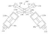
- a second exercise system constructed according to the principles of the present inventionis designated as 200 in FIGS. 4–5 .
- the system 200may similarly be described in terms of a pair of known selectorized dumbbells 90 a and 90 b disposed on a novel stand (that is relatively taller than the previous stand).
- a weight base or cradle 229 a or 229 bis provided for each dumbbell 90 a and 90 b to support the associated weight plates in proper alignment when not in use.
- the cradles 229 a and 229 bare mounted on respective first and second dumbbell supports 220 a and 220 b by bolts (not shown) or other suitable means.
- the bottom of each cradle 229 a and 229 bis preferably configured to register with a respective dumbbell support 220 a or 220 b.
- Each dumbbell support 220 a and 220 bmay be described as a generally L-shaped member having a leg or vertical portion that is supported by an underlying floor surface, and a beam or horizontal portion that supports a respective dumbbell 90 a or 90 b , and that is rotatably connected to an intermediate frame member 210 .
- Each vertical portionterminates in a lower distal end, to which a respective caster or roller assembly 232 is preferably mounted.
- Each horizontal portionterminates in a distal end that is rigidly connected to a respective sleeve (by welding or other suitable means).
- the intermediate frame member 210may be described in terms of a generally V-shaped member 212 having first and second legs that extend away from a common juncture and then downward toward the floor, and a post that extends upward from the juncture to support the sleeves.
- Caster or roller assemblies 231are mounted on the lower distal ends of the member 212
- another caster or roller assembly 230is mounted on the V-shaped member 212 beneath the common juncture (and the post).
- Each sleeveis rotatably mounted on the post for rotation about a common vertical axis.
- the distal horizontal ends of respective dumbbell supports 320 a and 320 bare angled in opposite upward and downward directions to arrive at different elevations along the post.
- a lower collar, an intermediate collar, and an upper collarare secured to the post (by set screws or other suitable means) at positions above and below respective sleeves to prevent translational movement of the sleeves, and to function as bushings between the post and the sleeves.
- An end cap 202is mounted on top of the post, but an accessory tray could be provided in its place (as further discussed below).
- the supports 220 a and 220 bcooperate with the frame member 210 to define a stand that may be rearranged or transformed between multiple configurations.
- FIG. 5shows a relatively compact configuration, wherein load bearing portions of the dumbbell supports 220 a and 220 b extend parallel to one another, and the dumbbells 90 a and 90 b are adjacent one another (with a distance of about six inches defined between their handles).
- FIG. 4shows a spread configuration, wherein the load bearing portions of the dumbbell supports 220 a and 220 b cooperate to define a V-shaped arrangement, and a person may stand between the dumbbells 90 a and 90 b (because a relatively greater distance of about twenty inches is now defined between their handles).
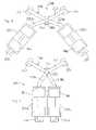
- a third exercise system constructed according to the principles of the present inventionis designated as 300 in FIGS. 6–9 .
- the system 300may similarly be described in terms of a pair of known selectorized dumbbells 90 a and 90 b disposed on a novel stand that is similar in height to the stand of the second system 200 .
- a weight base or cradle 329 a or 329 bis provided for each dumbbell 90 a and 90 b to support the weight plates in proper alignment when not in use.
- the cradles 329 a and 329 bare mounted on respective first and second dumbbell supports 320 a and 320 b by bolts (not shown) or other suitable means.
- the bottom of each cradle 329 a and 329 bis preferably configured to register with a respective dumbbell support 320 a or 320 b.
- the first dumbbell support 320 amay be described as an inverted, generally U-shaped member having first and second vertical portions or legs, and a generally horizontal portion or beam that extends therebetween and supports the first dumbbell 90 a .
- a caster or roller assembly 330is mounted to a lower distal end of the first vertical portion, and a base or foot 303 is rigidly mounted on a lower distal end of the second vertical portion.
- the foot 303preferably includes a steel plate that is welded to the support 320 a , and a rubber pad that is secured beneath the plate.
- the second dumbbell support 320 bmay be described as a generally L-shaped leg having a vertical portion that terminates in a lower distal end, to which a caster or roller assembly 330 is mounted, and a horizontal portion that supports the second dumbbell 90 b.
- the horizontal portion of the second dumbbell support 320 bterminates in a distal end that is rigidly connected to a sleeve 325 , which in turn, is rotatably mounted on the vertical, foot supported portion of the other dumbbell support 320 a .
- Lower and upper collars 327are disposed at opposite ends of the sleeve 325 , and are secured to the dumbbell support 320 a (by set screws or other suitable means) to prevent translational movement of the sleeve 325 , and to function as bushings between the support 320 a and the sleeve 325 .
- the distal horizontal end portion of the second dumbbell support 320 bis angled downward toward a vertically extending portion of the support 320 a .
- the vertical, caster supported portions of the supports 320 a and 320 bare preferably bent as shown to enhance the stability of the stand and provide foot room for a person to stand just in front of the weight bases 329 a and 329 b.
- the standmay be rearranged or transformed between multiple configurations.
- FIG. 6shows a relatively compact configuration, wherein load bearing portions of the dumbbell supports 320 a and 320 b extend parallel to one another, and the dumbbells 90 a and 90 b are adjacent one another (with a distance of about six inches defined between their handles).
- FIG. 9shows a spread configuration, wherein the load bearing portions of the dumbbell supports 320 a and 320 b cooperate to define a generally V-shaped arrangement, and a person may stand between the dumbbells 90 a and 90 b (because a relatively greater distance of about twenty inches is now defined between their handles).
- meansmay be provided for biasing the dumbbell supports toward one or more desired positions, locking the supports in desired positions, and/or preventing rotation of the supports beyond a certain position.
- a collarmay be secured to one of the supports, and a leaf spring may be secured to the other support to snap into and out of circumferentially spaced notches provided in the collar.
- snap buttons or detent pinsmay be configured and arranged to insert through holes in overlapping portions of the supports, or through holes in overlapping portions of the supports and an intermediate frame member.
- collars or bracketsmay be secured to respective supports or to a support and an intermediate frame member to pivot through a desired angle before blocking one another.
- FIGS. 6–8show an optional accessory tray 360 (in dashed lines) mounted on top of the dumbbell support 320 b .
- the tray 360includes a relatively deep circular compartment 363 for a water bottle, and a relatively shallow rectangular compartment for personal items.
- the configuration of the tray 360takes advantage of the downward bend in the support 320 b .
- FIGS. 6–8also show an optional flip chart assembly 370 rotatably mounted on the other support 320 a .
- the flip chart assembly 370includes a wire form, generally ?-shaped frame that extends upward from the support 320 a .
- the flip chartis bound on type by circular or spiral rings that fit onto the top of the wire form frame.
- a boltmay be inserted through vertically aligned holes in overlapping portions of the supports, in which case, a flat interface may be provided between the supports by using flat tubes and/or suitable configured washers or other bearing members on the tubes.
- the support tubesmay be configured in different ways to achieve different results.
- C-shaped supportsmay be used in such a manner that the lower distal ends are pivotally interconnected, and the upper distal ends are cantilevered, in which case the height of the dumbbell supports may be adjusted by selectively telescoping the vertical portions of the supports.
Landscapes
- Health & Medical Sciences (AREA)
- General Health & Medical Sciences (AREA)
- Physical Education & Sports Medicine (AREA)
- Rehabilitation Tools (AREA)
- Auxiliary Devices For Music (AREA)
- Sorting Of Articles (AREA)
Abstract
Description
Claims (13)
Priority Applications (2)
| Application Number | Priority Date | Filing Date | Title |
|---|---|---|---|
| US10/428,179US7029425B2 (en) | 2003-04-30 | 2003-04-30 | Methods and apparatus for supporting exercise dumbbells |
| PCT/US2004/012261WO2004098719A2 (en) | 2003-04-30 | 2004-04-20 | Methods and apparatus for suporting exercise dumbbells |
Applications Claiming Priority (1)
| Application Number | Priority Date | Filing Date | Title |
|---|---|---|---|
| US10/428,179US7029425B2 (en) | 2003-04-30 | 2003-04-30 | Methods and apparatus for supporting exercise dumbbells |
Publications (2)
| Publication Number | Publication Date |
|---|---|
| US20040220024A1 US20040220024A1 (en) | 2004-11-04 |
| US7029425B2true US7029425B2 (en) | 2006-04-18 |
Family
ID=33310347
Family Applications (1)
| Application Number | Title | Priority Date | Filing Date |
|---|---|---|---|
| US10/428,179Expired - LifetimeUS7029425B2 (en) | 2003-04-30 | 2003-04-30 | Methods and apparatus for supporting exercise dumbbells |
Country Status (2)
| Country | Link |
|---|---|
| US (1) | US7029425B2 (en) |
| WO (1) | WO2004098719A2 (en) |
Cited By (26)
| Publication number | Priority date | Publication date | Assignee | Title |
|---|---|---|---|---|
| US20070299387A1 (en)* | 2006-04-24 | 2007-12-27 | Williams Michael S | System and method for multi-instrument surgical access using a single access port |
| US7534198B1 (en)* | 2008-03-04 | 2009-05-19 | Strong Fredric D | Dumbbell supporting apparatus |
| US20090227843A1 (en)* | 2007-09-12 | 2009-09-10 | Smith Jeffrey A | Multi-instrument access devices and systems |
| US20100179032A1 (en)* | 2009-01-14 | 2010-07-15 | Perry David A | System and apparatus for storage and use of dumbbells |
| US7803095B1 (en)* | 2006-08-18 | 2010-09-28 | Lagree Sebastien A | Exercise machine |
| US20110045956A1 (en)* | 2009-07-31 | 2011-02-24 | Matthew Colledge | Weightlifting device with mechanism for disengaging weight plates |
| US20110060183A1 (en)* | 2007-09-12 | 2011-03-10 | Salvatore Castro | Multi-instrument access devices and systems |
| US20110184231A1 (en)* | 2009-07-28 | 2011-07-28 | Page Brett M | Deflectable instrument ports |
| US20110230723A1 (en)* | 2008-12-29 | 2011-09-22 | Salvatore Castro | Active Instrument Port System for Minimally-Invasive Surgical Procedures |
| US8602953B2 (en) | 2011-02-04 | 2013-12-10 | Amy Christine Jordan | Reformer apparatus having integral ergonomic purchase translatable into deployed and stowed positions |
| US8641585B2 (en) | 2011-05-20 | 2014-02-04 | Sebastien A. LaGree | Exercise machine |
| US8771153B2 (en) | 2010-11-08 | 2014-07-08 | Icon Ip, Inc. | Exercise weight bar with rotating handle and cam selection device |
| US9597545B1 (en) | 2011-05-20 | 2017-03-21 | Lagree Technologies, Inc. | Exercise machine handle system |
| US9717945B2 (en) | 2011-05-20 | 2017-08-01 | Lagree Technologies, Inc. | Multiple position locking handle for an exercise machine |
| US10188890B2 (en) | 2013-12-26 | 2019-01-29 | Icon Health & Fitness, Inc. | Magnetic resistance mechanism in a cable machine |
| US10213641B2 (en) | 2011-05-20 | 2019-02-26 | Lagree Technologies, Inc. | Exercise machine handle system |
| US10252109B2 (en) | 2016-05-13 | 2019-04-09 | Icon Health & Fitness, Inc. | Weight platform treadmill |
| US10279212B2 (en) | 2013-03-14 | 2019-05-07 | Icon Health & Fitness, Inc. | Strength training apparatus with flywheel and related methods |
| US10293211B2 (en) | 2016-03-18 | 2019-05-21 | Icon Health & Fitness, Inc. | Coordinated weight selection |
| USD853506S1 (en) | 2017-10-05 | 2019-07-09 | Brunswick Corporation | Support rack for free weights |
| US10426989B2 (en) | 2014-06-09 | 2019-10-01 | Icon Health & Fitness, Inc. | Cable system incorporated into a treadmill |
| US10441840B2 (en) | 2016-03-18 | 2019-10-15 | Icon Health & Fitness, Inc. | Collapsible strength exercise machine |
| US10449416B2 (en) | 2015-08-26 | 2019-10-22 | Icon Health & Fitness, Inc. | Strength exercise mechanisms |
| US10493321B2 (en) | 2016-10-20 | 2019-12-03 | Lagree Technologies, Inc. | Exercise machine with adjustable handles |
| US10661114B2 (en) | 2016-11-01 | 2020-05-26 | Icon Health & Fitness, Inc. | Body weight lift mechanism on treadmill |
| US10940360B2 (en) | 2015-08-26 | 2021-03-09 | Icon Health & Fitness, Inc. | Strength exercise mechanisms |
Families Citing this family (2)
| Publication number | Priority date | Publication date | Assignee | Title |
|---|---|---|---|---|
| US7025713B2 (en)* | 2003-10-13 | 2006-04-11 | Icon Ip, Inc. | Weight lifting system with internal cam mechanism |
| US11273338B2 (en)* | 2020-04-21 | 2022-03-15 | Floriey Industries International Co. | Dumbbell and barbell supporting system |
Citations (2)
| Publication number | Priority date | Publication date | Assignee | Title |
|---|---|---|---|---|
| US5630776A (en)* | 1996-06-12 | 1997-05-20 | Yang; Lien-Chuan | Folding dumbell rest |
| US6447428B1 (en)* | 1999-11-08 | 2002-09-10 | Motorcizer Corporation | Exercise device |
Family Cites Families (3)
| Publication number | Priority date | Publication date | Assignee | Title |
|---|---|---|---|---|
| USD443660S1 (en)* | 2000-03-17 | 2001-06-12 | Louis Ceppo | Rear entry adjustable dumbbell holder stand |
| USD441813S1 (en)* | 2000-08-22 | 2001-05-08 | Louis Ceppo | Dumbbell holder stands support |
| USD487490S1 (en)* | 2002-05-30 | 2004-03-09 | Steven Lee Evans | Elevated dumbbell holder |
- 2003
- 2003-04-30USUS10/428,179patent/US7029425B2/ennot_activeExpired - Lifetime
- 2004
- 2004-04-20WOPCT/US2004/012261patent/WO2004098719A2/enactiveApplication Filing
Patent Citations (2)
| Publication number | Priority date | Publication date | Assignee | Title |
|---|---|---|---|---|
| US5630776A (en)* | 1996-06-12 | 1997-05-20 | Yang; Lien-Chuan | Folding dumbell rest |
| US6447428B1 (en)* | 1999-11-08 | 2002-09-10 | Motorcizer Corporation | Exercise device |
Cited By (36)
| Publication number | Priority date | Publication date | Assignee | Title |
|---|---|---|---|---|
| US20070299387A1 (en)* | 2006-04-24 | 2007-12-27 | Williams Michael S | System and method for multi-instrument surgical access using a single access port |
| US7803095B1 (en)* | 2006-08-18 | 2010-09-28 | Lagree Sebastien A | Exercise machine |
| US20110060183A1 (en)* | 2007-09-12 | 2011-03-10 | Salvatore Castro | Multi-instrument access devices and systems |
| US20090227843A1 (en)* | 2007-09-12 | 2009-09-10 | Smith Jeffrey A | Multi-instrument access devices and systems |
| US7534198B1 (en)* | 2008-03-04 | 2009-05-19 | Strong Fredric D | Dumbbell supporting apparatus |
| US20110230723A1 (en)* | 2008-12-29 | 2011-09-22 | Salvatore Castro | Active Instrument Port System for Minimally-Invasive Surgical Procedures |
| US8323159B2 (en)* | 2009-01-14 | 2012-12-04 | Mesacor, Inc. | System and apparatus for storage and use of dumbbells |
| US20100179032A1 (en)* | 2009-01-14 | 2010-07-15 | Perry David A | System and apparatus for storage and use of dumbbells |
| US20110184231A1 (en)* | 2009-07-28 | 2011-07-28 | Page Brett M | Deflectable instrument ports |
| US20110045956A1 (en)* | 2009-07-31 | 2011-02-24 | Matthew Colledge | Weightlifting device with mechanism for disengaging weight plates |
| US8298125B2 (en) | 2009-07-31 | 2012-10-30 | Icon Health & Fitness, Inc. | Weightlifting device with mechanism for disengaging weight plates |
| US8771153B2 (en) | 2010-11-08 | 2014-07-08 | Icon Ip, Inc. | Exercise weight bar with rotating handle and cam selection device |
| US8602953B2 (en) | 2011-02-04 | 2013-12-10 | Amy Christine Jordan | Reformer apparatus having integral ergonomic purchase translatable into deployed and stowed positions |
| US9717945B2 (en) | 2011-05-20 | 2017-08-01 | Lagree Technologies, Inc. | Multiple position locking handle for an exercise machine |
| US8641585B2 (en) | 2011-05-20 | 2014-02-04 | Sebastien A. LaGree | Exercise machine |
| US9597545B1 (en) | 2011-05-20 | 2017-03-21 | Lagree Technologies, Inc. | Exercise machine handle system |
| US10213641B2 (en) | 2011-05-20 | 2019-02-26 | Lagree Technologies, Inc. | Exercise machine handle system |
| US10279212B2 (en) | 2013-03-14 | 2019-05-07 | Icon Health & Fitness, Inc. | Strength training apparatus with flywheel and related methods |
| US11148004B1 (en) | 2013-10-23 | 2021-10-19 | Lagree Technologies, Inc. | Exercise machine handle system |
| US11759671B2 (en) | 2013-10-23 | 2023-09-19 | Lagree Technologies, Inc. | Exercise machine handle system |
| US10744370B1 (en) | 2013-10-23 | 2020-08-18 | Lagree Technologies, Inc. | Exercise machine handle system |
| US10188890B2 (en) | 2013-12-26 | 2019-01-29 | Icon Health & Fitness, Inc. | Magnetic resistance mechanism in a cable machine |
| US10426989B2 (en) | 2014-06-09 | 2019-10-01 | Icon Health & Fitness, Inc. | Cable system incorporated into a treadmill |
| US10449416B2 (en) | 2015-08-26 | 2019-10-22 | Icon Health & Fitness, Inc. | Strength exercise mechanisms |
| US10940360B2 (en) | 2015-08-26 | 2021-03-09 | Icon Health & Fitness, Inc. | Strength exercise mechanisms |
| US10293211B2 (en) | 2016-03-18 | 2019-05-21 | Icon Health & Fitness, Inc. | Coordinated weight selection |
| US10441840B2 (en) | 2016-03-18 | 2019-10-15 | Icon Health & Fitness, Inc. | Collapsible strength exercise machine |
| US10252109B2 (en) | 2016-05-13 | 2019-04-09 | Icon Health & Fitness, Inc. | Weight platform treadmill |
| US10493321B2 (en) | 2016-10-20 | 2019-12-03 | Lagree Technologies, Inc. | Exercise machine with adjustable handles |
| US11154749B1 (en) | 2016-10-20 | 2021-10-26 | Lagree Technologies, Inc. | Exercise machine with adjustable handles |
| US11565151B2 (en) | 2016-10-20 | 2023-01-31 | Lagree Technologies, Inc. | Exercise machine with adjustable handles |
| US11980789B2 (en) | 2016-10-20 | 2024-05-14 | Lagree Technologies, Inc. | Exercise machine with adjustable handles |
| US12246216B2 (en) | 2016-10-20 | 2025-03-11 | Lagree Technologies, Inc. | Exercise machine with adjustable handles |
| US10661114B2 (en) | 2016-11-01 | 2020-05-26 | Icon Health & Fitness, Inc. | Body weight lift mechanism on treadmill |
| USD861806S1 (en) | 2017-10-05 | 2019-10-01 | Brunswick Corporation | Support rack for free weights |
| USD853506S1 (en) | 2017-10-05 | 2019-07-09 | Brunswick Corporation | Support rack for free weights |
Also Published As
| Publication number | Publication date |
|---|---|
| US20040220024A1 (en) | 2004-11-04 |
| WO2004098719A2 (en) | 2004-11-18 |
| WO2004098719A3 (en) | 2004-12-23 |
Similar Documents
| Publication | Publication Date | Title |
|---|---|---|
| US7029425B2 (en) | Methods and apparatus for supporting exercise dumbbells | |
| US7125371B2 (en) | Adjustable bodyweight exercise apparatus | |
| US4316609A (en) | Bench mounted weight lifting exerciser | |
| US4382596A (en) | Weight lifting type exercising device | |
| EP1988977B1 (en) | Compact gym | |
| US4856773A (en) | Weightlifting exercise device | |
| US5387169A (en) | Horizontal stepper | |
| US3614097A (en) | Weight lifting exercising apparatus | |
| US4784384A (en) | Weightlifting exercise device | |
| US5725460A (en) | Adjustable weight lifter's bench | |
| US4861025A (en) | Articulated storable exercise bench | |
| US4883268A (en) | Compact, portable, rowing type exercise apparatus usable by a chair-seated exerciser | |
| US20020132710A1 (en) | Exercise apparatus | |
| US6030324A (en) | Multi-purpose exercise bench | |
| JPS6137177A (en) | Training unit attached to wall | |
| US9498664B2 (en) | Foot, leg and arm support for exercise | |
| WO1996016701A9 (en) | Weight-bar support structure with retractable arms | |
| WO1996016701A1 (en) | Weight-bar support structure with retractable arms | |
| US20050003937A1 (en) | Exercise bench and dumbell combination | |
| US20120157271A1 (en) | Adjustable Dumbbell Support Stand | |
| US20180290016A1 (en) | Leg Stretching Apparatus | |
| US9925447B2 (en) | Portable, adjustable support structure for a speed bag | |
| US6981934B1 (en) | Machine for doing squats and other exercises | |
| US6589142B2 (en) | Exercise apparatus having a sliding carriage | |
| US20180304116A1 (en) | Foldable climbing exercise device |
Legal Events
| Date | Code | Title | Description |
|---|---|---|---|
| STCF | Information on status: patent grant | Free format text:PATENTED CASE | |
| FPAY | Fee payment | Year of fee payment:4 | |
| AS | Assignment | Owner name:CORE HEALTH & FITNESS, LLC, WASHINGTON Free format text:NUNC PRO TUNC ASSIGNMENT;ASSIGNOR:KRULL, MARK A;REEL/FRAME:031177/0834 Effective date:20130906 | |
| REMI | Maintenance fee reminder mailed | ||
| FEPP | Fee payment procedure | Free format text:PAYOR NUMBER ASSIGNED (ORIGINAL EVENT CODE: ASPN); ENTITY STATUS OF PATENT OWNER: SMALL ENTITY Free format text:PAT HOLDER NO LONGER CLAIMS SMALL ENTITY STATUS, ENTITY STATUS SET TO UNDISCOUNTED (ORIGINAL EVENT CODE: STOL); ENTITY STATUS OF PATENT OWNER: SMALL ENTITY | |
| FPAY | Fee payment | Year of fee payment:8 | |
| SULP | Surcharge for late payment | Year of fee payment:7 | |
| FEPP | Fee payment procedure | Free format text:MAINTENANCE FEE REMINDER MAILED (ORIGINAL EVENT CODE: REM.) | |
| FEPP | Fee payment procedure | Free format text:11.5 YR SURCHARGE- LATE PMT W/IN 6 MO, SMALL ENTITY (ORIGINAL EVENT CODE: M2556) Free format text:ENTITY STATUS SET TO SMALL (ORIGINAL EVENT CODE: SMAL) | |
| MAFP | Maintenance fee payment | Free format text:PAYMENT OF MAINTENANCE FEE, 12TH YR, SMALL ENTITY (ORIGINAL EVENT CODE: M2553) Year of fee payment:12 | |
| AS | Assignment | Owner name:BRUNO INTELLECTUAL RESERVE LLC, OHIO Free format text:ASSIGNMENT OF ASSIGNORS INTEREST;ASSIGNOR:CORE HEALTH & FITNESS, LLC;REEL/FRAME:053358/0378 Effective date:20200730 |