US7029325B2 - Triaxial connector adapter and method - Google Patents
Triaxial connector adapter and methodDownload PDFInfo
- Publication number
- US7029325B2 US7029325B2US10/929,638US92963804AUS7029325B2US 7029325 B2US7029325 B2US 7029325B2US 92963804 AUS92963804 AUS 92963804AUS 7029325 B2US7029325 B2US 7029325B2
- Authority
- US
- United States
- Prior art keywords
- connector
- adapter
- mounting
- yoke
- opening
- Prior art date
- Legal status (The legal status is an assumption and is not a legal conclusion. Google has not performed a legal analysis and makes no representation as to the accuracy of the status listed.)
- Expired - Lifetime
Links
Images


Classifications
- H—ELECTRICITY
- H01—ELECTRIC ELEMENTS
- H01R—ELECTRICALLY-CONDUCTIVE CONNECTIONS; STRUCTURAL ASSOCIATIONS OF A PLURALITY OF MUTUALLY-INSULATED ELECTRICAL CONNECTING ELEMENTS; COUPLING DEVICES; CURRENT COLLECTORS
- H01R9/00—Structural associations of a plurality of mutually-insulated electrical connecting elements, e.g. terminal strips or terminal blocks; Terminals or binding posts mounted upon a base or in a case; Bases therefor
- H01R9/03—Connectors arranged to contact a plurality of the conductors of a multiconductor cable, e.g. tapping connections
- H01R9/05—Connectors arranged to contact a plurality of the conductors of a multiconductor cable, e.g. tapping connections for coaxial cables
- H—ELECTRICITY
- H01—ELECTRIC ELEMENTS
- H01R—ELECTRICALLY-CONDUCTIVE CONNECTIONS; STRUCTURAL ASSOCIATIONS OF A PLURALITY OF MUTUALLY-INSULATED ELECTRICAL CONNECTING ELEMENTS; COUPLING DEVICES; CURRENT COLLECTORS
- H01R13/00—Details of coupling devices of the kinds covered by groups H01R12/70 or H01R24/00 - H01R33/00
- H01R13/73—Means for mounting coupling parts to apparatus or structures, e.g. to a wall
- H01R13/74—Means for mounting coupling parts in openings of a panel
- H01R13/748—Means for mounting coupling parts in openings of a panel using one or more screws
- H—ELECTRICITY
- H01—ELECTRIC ELEMENTS
- H01R—ELECTRICALLY-CONDUCTIVE CONNECTIONS; STRUCTURAL ASSOCIATIONS OF A PLURALITY OF MUTUALLY-INSULATED ELECTRICAL CONNECTING ELEMENTS; COUPLING DEVICES; CURRENT COLLECTORS
- H01R13/00—Details of coupling devices of the kinds covered by groups H01R12/70 or H01R24/00 - H01R33/00
- H01R13/73—Means for mounting coupling parts to apparatus or structures, e.g. to a wall
- H—ELECTRICITY
- H01—ELECTRIC ELEMENTS
- H01R—ELECTRICALLY-CONDUCTIVE CONNECTIONS; STRUCTURAL ASSOCIATIONS OF A PLURALITY OF MUTUALLY-INSULATED ELECTRICAL CONNECTING ELEMENTS; COUPLING DEVICES; CURRENT COLLECTORS
- H01R9/00—Structural associations of a plurality of mutually-insulated electrical connecting elements, e.g. terminal strips or terminal blocks; Terminals or binding posts mounted upon a base or in a case; Bases therefor
- H01R9/03—Connectors arranged to contact a plurality of the conductors of a multiconductor cable, e.g. tapping connections
- H01R9/05—Connectors arranged to contact a plurality of the conductors of a multiconductor cable, e.g. tapping connections for coaxial cables
- H01R9/0512—Connections to an additional grounding conductor
- H—ELECTRICITY
- H01—ELECTRIC ELEMENTS
- H01R—ELECTRICALLY-CONDUCTIVE CONNECTIONS; STRUCTURAL ASSOCIATIONS OF A PLURALITY OF MUTUALLY-INSULATED ELECTRICAL CONNECTING ELEMENTS; COUPLING DEVICES; CURRENT COLLECTORS
- H01R2103/00—Two poles
- H—ELECTRICITY
- H01—ELECTRIC ELEMENTS
- H01R—ELECTRICALLY-CONDUCTIVE CONNECTIONS; STRUCTURAL ASSOCIATIONS OF A PLURALITY OF MUTUALLY-INSULATED ELECTRICAL CONNECTING ELEMENTS; COUPLING DEVICES; CURRENT COLLECTORS
- H01R9/00—Structural associations of a plurality of mutually-insulated electrical connecting elements, e.g. terminal strips or terminal blocks; Terminals or binding posts mounted upon a base or in a case; Bases therefor
- H01R9/03—Connectors arranged to contact a plurality of the conductors of a multiconductor cable, e.g. tapping connections
- H01R9/05—Connectors arranged to contact a plurality of the conductors of a multiconductor cable, e.g. tapping connections for coaxial cables
- H01R9/0518—Connection to outer conductor by crimping or by crimping ferrule
Definitions
- the present inventionrelates to transmission line connectors, more specifically to transmission line connectors for connecting to cables including center conductors shielded from one or more longitudinally extending coaxial conductors.
- Connectors for use with electrically conductive transmission cablesprovide electrical connectivity with the center conductor of the cable as well as to other coaxially arranged conductors with the cable. Some of these cables include a center conductor and one additional coaxial conductor (coaxial cables) and while others cables include two additional coaxial conductors (triaxial cables).
- the center conductor of a cable of either typeis physically and electrically linked to the center conductor of the connector, and the connector can then be used with a mating connector.
- U.S. Pat. Nos. 5,967,852 and 6,109,963 to ADC Telecommunications, Inc.concern connectors of this type. Mounting panels for connectors of this type are also known, as shown in U.S. Pat. Nos. 6,146,192 and 6,231,380. Continued development in this area is desired.
- the present inventionrelates to a center conductor insulator for use in a coaxial cable transmission line connector.
- the insulatorincludes a tapered entry for a pin connected with the center conductor of the cable.
- a front shell assembly for use with a connectorincludes center conductor insulator with a tapered entry.
- the present inventionfurther relates to a compression ring assembly for holding a transmission line connector to a transmission line cable.
- the assemblyincludes a compressible collet urged inward by a sloped inner wall of a rear seal.
- the colletincludes slots extending from each end of the collet.
- the present inventionalso relates to a conversion kit for converting a transmission line connector for use with coaxial conductor cable from one gender or style to a different gender or style.
- the present applicationfurther relates to a mounting kit for mounting transmission line connectors of different styles or genders to a panel including a yoke and an adapter.
- FIG. 1is a perspective view of a first triaxial connector according to the present invention.
- FIG. 2is a perspective view of a second triaxial connector according to the present invention and adapted to mate with the connector of FIG. 1 .
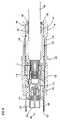
- FIG. 3is a cross-sectional view of the connector of FIG. 1 .
- FIG. 4is a cross-sectional view of the connector of FIG. 2 .
- FIG. 5is an exploded view of some of the internal elements of the cable end of the connector of FIG. 1 .
- FIG. 6is a first front perspective view of the collet shown in FIG. 5 .
- FIG. 7is a rear perspective view of the collet of FIG. 6 .
- FIG. 7Ais a second front perspective view of the collet shown in FIG. 6 .
- FIG. 8is a rear view of the collet of FIG. 6 .
- FIG. 9is a side view of the collet of FIG. 6 .
- FIG. 10is a front view of the collet of FIG. 6 .
- FIG. 10Ais a cross-sectional view of the collet of FIG. 6 taken along line A—A in FIG. 10 .
- FIG. 11is a front perspective view of the rear seal of FIG. 5 .
- FIG. 12is a rear view of the rear seal of FIG. 11 .
- FIG. 13is a front view of the rear seal of FIG. 11 .
- FIG. 14is a cross-sectional side view of the rear seal of FIG. 11 taken along line A—A in FIG. 13 .
- FIG. 15is a perspective of an assembled first triaxial connector conversion kit according to the present invention.
- FIG. 16is an exploded perspective view of the conversion kit of FIG. 15 .
- FIG. 17is a perspective view of the front shell assembly of the conversion kit of FIG. 16 mounted to an internal assembly of a triaxial connector.
- FIG. 18is an exploded perspective view of the front shell assembly of FIG. 17 .
- FIG. 19is a front view of the front shell assembly of FIG. 17 .
- FIG. 20is a cross-sectional view of the front shell assembly of FIG. 17 taken along line A—A of FIG. 19 .
- FIG. 21is a perspective of an assembled second triaxial connector conversion kit according to the present invention.
- FIG. 22is an exploded perspective view of the conversion kit of FIG. 21 .
- FIG. 23is a perspective view of the front shell assembly of the conversion kit of FIG. 22 mounted to an internal assembly of a triaxial connector.
- FIG. 24is an exploded perspective view of the front shell assembly of FIG. 22 .
- FIG. 25is a front view of the front shell assembly of FIG. 22 .
- FIG. 26is a cross-sectional view of the front shell assembly of FIG. 22 taken along line A—A of FIG. 25 .
- FIG. 27is a cross-sectional view of the center conductor insulator of the front shell assemblies of the triaxial connector conversion kits of FIGS. 15 and 21 .
- FIG. 28is a perspective view of a connector during an initial step of a first conversion procedure according to the present invention, with the arrows showing the direction of movement for the removal of the front connector body.
- FIG. 29is a perspective view of the connector of FIG. 28 during a later step of the conversion process, with the arrows showing the direction of movement for the removal of the front shell assembly.
- FIG. 30is a perspective view of the connector of FIG. 29 during a later step of the conversion process, with the arrows showing the direction of movement for the replacement of the front shell assembly.
- FIG. 31is a perspective view of the connector of FIG. 30 during a later step of the conversion process, with the arrows showing the direction of movement for the replacement of the front connector body.
- FIG. 32is a perspective view of the connector of FIG. 31 during a later step of the conversion process, with the arrows showing the direction of movement for securing the replacement front connector body.
- FIG. 33is a perspective view of a connector during an initial step of a second conversion process according to the present invention, with the arrows showing the direction of movement for the removal of the front connector body.
- FIG. 34is a perspective view of the connector of FIG. 33 during a later step of the conversion process, with the arrows showing the direction of movement for the removal of the front shell assembly.
- FIG. 35is a perspective view of the connector of FIG. 34 during a later step of the conversion process, with the arrows showing the direction of movement for the replacement of the front shell assembly.
- FIG. 36is a perspective view of the connector of FIG. 35 during a later step of the conversion process, with the arrows showing the direction of movement for the replacement of the front connector body.
- FIG. 37is a perspective view of the connector of FIG. 36 during a later step of the conversion process, with the arrows showing the direction of movement for securing the replacement front connector body.
- FIG. 38is a front perspective exploded view of a prior art female telecommunications connector with a mounting yoke about the connector and a plate to which the mounting yoke is mounted.
- FIG. 39is a front perspective exploded view of the telecommunications connector of FIG. 1 with an adapter about the connector, the mounting yoke and plate to which the mounting yoke is mounted of FIG. 38 about the adapter.
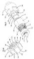
- FIG. 40is a front perspective exploded view of the adapter and mounting yoke of FIG. 39 .
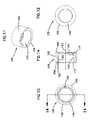
- FIG. 41is a front view of the adapter of FIG. 39 .
- FIG. 42is a rear view of the adapter of FIG. 39 .
- FIG. 43is a cross-sectional view of the adapter of FIG. 39 taken along line B—B in FIG. 42 .
- FIG. 44is a cross-sectional view of the adapter of FIG. 39 taken along line A—A in FIG. 43 .
- the stylemay differ between the male/female nature of the center conductors and the sleeves of the connectors.
- the stylesmay also differ in terms of the locking mechanisms which hold the connectors together.
- Two styles of connectorsare illustrated in the drawings FIGS. 1 and 2 and FIG. 38 . These styles differ with respect to the male/female nature of the connector elements and in the locking mechanism.
- One aspect of the present inventionrelates to converting from one style of connector to another style of connector.
- Various other aspects of the present inventionrelate to mounting connectors to cables with a cable clamp.
- Other aspects of the present inventionrelate to the connector elements including the center conductor insulator.
- Still further elements of the present inventionrelate to the use of the connectors with mounting panels.
- a first triaxial connector 100including a front outer body 102 , an endcap 104 , a mating opening 106 and a cable 108 .
- Cable 108includes a center conductor 109 electrically linked to a jack center conductor 112 by center conductor pin 110 .
- Center conductor 112is held within a center conductor insulator 114 within a front shell 116 .
- Front shell 116is electrically linked to a first coaxial conductor 118 within cable 108 .
- Outer insulator 120electrically isolates front shell 116 from front outer body 102 , which is electrically linked to a second coaxial conductor 122 within cable 108 .
- Front outer body 102includes a front ring 124 which defines the entrance to mating opening 106 .
- Endcap 104is threadably mounted to a threaded insert 128 .
- Captured between endcap 104 and threaded insert 126are a rear seal 128 and a collet 130 which cooperate to hold connector 100 to cable 108 .
- On endcap 104are two pairs of opposing wrench flats 134 and on front outer body 102 are two pairs of opposing mounting flats 136 .
- a first water sealsuch as o-ring 141 is located between cable 108 and endcap 104 and a second water seal such as o-ring 141 is located between threaded insert 126 and endcap 104 .
- a third water sealsuch as o-ring 141 is located between threaded insert 126 and front outer body 102 .
- a second triaxial connector 200is shown, with a front outer body 202 , an endcap 104 , a mating end 206 and a cable 108 .
- On front outer body 202is a sliding lock sleeve 203 .
- Lock sleeve 203includes a releasable locking mechanism 205 that engages lock ring 103 and is similar to that in U.S. Pat. No. 3,160,457, the disclosure of which is incorporated herein by reference.
- Fingers 207release from lock ring 103 when the connectors are pulled apart. If tension is applied to cables 108 , ramp 209 tends to prevent fingers 207 from releasing lock ring 103 .
- Cable 108includes a center conductor 109 electrically linked to center conductor pin 110 .
- Center conductor pin 110is electrically linked to a center conductor 212 of held within a center conductor insulator 114 within a front shell 216 .
- Front shell 216is electrically linked to a first coaxial conductor 118 within cable 108 .
- Outer insulator 120electrically isolates front shell 216 from front outer body 202 , which is electrically linked to a second coaxial conductor 122 within cable 108 .
- Front outer body 202includes a front ring 224 which defines an entrance to mating opening 206 .
- Endcap 104is threadably mounted to a threaded insert 126 .
- a rear seal 128 and a collet 130Captured between endcap 104 and threaded insert 126 are a rear seal 128 and a collet 130 which cooperate to hold connector 200 to cable 108 .
- a first water sealsuch as o-ring 141 is located between cable 108 and endcap 104 and a second water seal such as o-ring 141 is located between threaded insert 126 and endcap 104 .
- a third water sealsuch as o-ring 141 is located between threaded insert 126 and front outer body 202 .
- FIG. 5further detail of the cooperation of endcap 104 , threaded insert 126 , rear seal 128 and collet 130 for mounting connectors 100 and 200 to cable 108 is shown.
- center conductor 109 of cable 108On an end of threaded insert 126 away from endcap 104 is shown center conductor 109 of cable 108 .
- Center conductor 110 of connector 100 or 200fits about center conductor 109 and is electrically insulated from first coaxial conductor 118 by middle dielectric 111 .
- first coaxial conductor 118is electrically insulated from second coaxial conductor 122 by inner jacket 121 .
- endcap 104is first placed about cable 108 , followed in turn by rear seal 128 , collet 130 and threaded insert 126 .
- An inner surface 138 of endcap 104engages rear seal 128 as endcap 104 and threaded insert 126 are threadably engaged, urging rear seal 128 over collet 130 .
- An inner wall 140 of rear seal 128is angled as shown in the FIGS. (and described in further detail below) and an outer surface 142 of collet 130 is similarly angled as shown in the FIGS. (and described in further detail below). Inner wall 140 and outer surface 142 cooperate to compress collet 130 about cable 108 as endcap 104 is drawn toward threaded insert 126 .
- Second coaxial conductor 122is electrically connected to threaded insert 126 by bending back second conductor 122 against threaded insert and placing ground washer 132 about the bent over portion of conductor 122 . Additional details regarding the general process of terminating cable 108 to a connector 100 or 200 are described in above-referenced U.S. Pat. Nos. 5,967,852 and 6,109,963, the disclosures of which are incorporated herein by reference.
- a portion of the connector structureis tightened about the outer jacket of the cable. This portion of the structure adds to the strength and integrity of the physical connection of the connector and the cable.
- the process of tightening the structure against the outer jacket of the cableshould secure the cable without causing damage to the cable and the conductors within the cable.
- Collet 130includes an end 144 which is directed toward threaded sleeve 126 and an end 148 which is directed toward endcap 104 , when collet 130 is used to secure a connector 100 or 200 to cable 108 .
- Extending from end 148 toward end 144are second slots 150 , which traverse some of a distance between end 148 and end 144 and extend from an inner wall 154 to outer surface 142 .
- slots 146 and 150are equal in number and equally spaced apart about a circumference of collet 130 .
- slots 146 and 150are shown, and it is anticipated that more or fewer slots 146 and 150 could be used in accordance with the present invention.
- Inner wall 154includes a series of ridges 156 to improve the ability of collet 130 to grip cable 108 .
- Outer surface 142defines an angle 152 with respect to line 153 , which is parallel to a central axis 151 and offset from axis 151 by a maximum diameter of end 144 . As shown, angle 152 is about 5 degrees, although it is anticipated that other angles may be used.
- Collet 130is preferably made of a material such as brass or other similar material which will react in the same manner to compression by rear seal 128 as described below.
- Rear seal 128includes an outer wall 162 , an end 160 which engages inner surface 138 of endcap 104 and an end 158 which is directed toward threaded insert 126 when rear seal 128 is used to compress collet 130 to secure a connector 100 or 200 to cable 108 .
- Inner wall 140defines an angle 166 with respect to a line 165 , which is parallel to a central axis 163 and offset from axis 163 by a maximum diameter of inner stop 164 .
- Inner stop 164is a ledge defining an end to inner wall 140 and providing a stop for collet 130 .
- Angle 166is approximately the same as angle 152 .
- a narrow end 168 of collet 130is smaller than a wide end 172 of inner wall 140 of rear seal 128 but larger than a narrow end 174 .
- a wide end 170 of collet 130is smaller than wide end 172 .
- inner wall 140engages outer surface 142 and the cooperation of angles 152 and 166 and slots 146 and 150 allows collet 130 to be compressed within rear seal 128 to a smaller diameter.
- inner wall 154 and ridges 156are compressed into a smaller diameter as well, and inner wall 154 and ridges 156 engage cable 108 , a shown in FIGS. 3 and 4 .
- collet 130When rear seal 128 is placed about collet 130 , collet 130 is urged inward, forcing the material in collet 130 to deform and slots 146 and 150 to narrow.
- the arrangement of slots 146 and 150allows inner wall 154 to maintain a uniform diameter from end 144 to end 148 , as slots 146 and 150 narrow as collet 130 is compressed.
- Rear seal 128 and collet 130combine to apply uniform pressure to cable 108 as collet 130 is compressed.
- a minimum diameter of inner wall 154may be limited by limiting the amount of compression rear seal 128 applies to collet 130 .
- Compression of collet 130may be limited by controlling the width of slots 146 and 150 , by inner stop 164 engages narrow end 168 of collet 130 , or by setting a torque limit to the amount of force that may be applied to endcap 104 urging rear seal about collet 130 .
- Connectors of one stylemay not physically compatible with connectors of another format. This means, for example, that a cable with a first style of connector may not be usable with a cable having a second style of connector, and vice versa.
- connectors 100 and 200mate with each other. However, connectors 100 and 200 do not mate with the connectors of U.S. Pat. Nos. 5,967,852 and 6,109,963, noted above. The mating ends do not physically fit together.
- Conversion kit 300allows second connector 200 to be converted to a first connector 100
- conversion kit 400allows first connector 100 to be converted to a second connector 200 . It is anticipated that conversion kits 300 and 400 can also be adapted to work with coaxial or triaxial connectors of other styles or gender in a manner similar to that described below. Kits 300 and 400 can be used to convert the connectors of U.S. Pat. Nos. 5,967,852 and 6,109,963 to connectors of a different style, like connectors 100 and 200 , without requiring cutting and reterminating the cable.
- Front shell assembly 178includes center conductor 112 , center conductor insulator 114 and front shell 116 .
- Front shell 116includes several longitudinally extending fingers 180 cooperating to define an opening 182 for receiving mating front shell 216 . As shown in the FIGS., there are six fingers 180 . It is anticipated that more or fewer fingers 180 may be used.
- Center conductor 112defines an opening 184 for receiving a mating center conductor 212 , and an opening 302 for receiving center conductor pin 110 .
- Front shell assembly 178is selectively removably mounted to a rear shell 304 .
- Rear shell 304is electrically connected to first coaxial conductor 118 and held to cable 108 by crimp sleeve 306 , which is crimped about inner jacket 121 .
- Intermediate insulator 308fits about crimp sleeve 308 between ground washer 132 and rear shell 304 , and insulates those parts from each other, to prevent electrically connecting first coaxial conductor 118 and second coaxial conductor 122 through connector 100 .
- Front shell 116includes an inner wall 186 defining a region 187 for receiving insulator 114 .
- Region 187has an inner shoulder 188 to stop insertion of insulator 114 at an appropriate depth.
- Region 187also includes a threaded portion 310 to permit selectively detachable mounting to rear shell 304 .
- Other types of selectively detachable mounting approachesmay also be used with the present invention, such as bayonet mounting.
- Front shell assembly 402includes center conductor 212 , insulator 114 and front shell 216 .
- Front shell 216includes a tubular portion 408 defining an opening 404 for insertion into a mating front shell 116 .
- Center conductor 212includes a front end 406 for insertion into a mating center conductor 112 , and an opening 302 for receiving center conductor pin 110 .
- Front shell assembly 402mounts to rear shell 304 in a similar manner to front shell assembly 178 and the remainder of connector 100 or 200 shown in FIG. 23 is the same as that shown in FIG. 17 .
- Front shell 216includes an inner wall 412 defining a region 414 for receiving insulator 114 .
- Region 414has an inner shoulder 410 to stop the insertion of insulator 114 at an appropriate depth.
- Region 414also includes a threaded portion 416 to permit selectively detachable mounting to rear shell 304 .
- Other types of selectively detachable mounting approachesmay also be used with the present invention, such as bayonet mounting.
- Insulator 114includes a central channel 190 for receiving center conductor 112 or center conductor 212 .
- a shoulder 192 within channel 190provides a positive stop for a center conductor inserted into channel 190 and stops insertion at an appropriate depth.
- An outer wall 188defines a diameter slightly larger than the inner diameter defined by either inner wall 412 of front shell 216 or inner wall 186 of front shell 116 , permitting insulator 114 to be firmly held within either region 414 or 187 , respectively. It is anticipated that pressfitting insulator 114 into a front shell 216 or 116 will firmly mount insulator 114 within region 414 or 187 against shoulder 410 or 188 , respectively.
- Insulator 114is a one-piece insulator made of an electrically insulative material such as Teflon or a similar material. It is anticipated that insulator 114 may be made by a variety of methods, including machining.
- Centering region 196provides an entry into opening 198 to guide center conductor pin into opening 302 .
- Centering region 196includes a sloped wall 194 defining a wider outer edge 195 and a narrower inner edge 193 , which is the same size as opening 198 .
- the funnel shape defined by centering region 196aids in the insertion of a center conductor pin 110 which may have been placed or moved off-center by forcing center conductor pin into alignment with opening 302 .
- Shaft portion 197 of insulator 114helps ensure that an off-center center conductor pin 110 within opening 302 does not force any portion of center conductor 112 or 212 into contact with front shell 116 or 216 , respectively.
- Shaft portion 197is narrower than a rear portion 199 and a front portion 189 to provide for improved impedance characteristics when insulator 114 is incorporated into a telecommunications connector.
- FIGS. 28 through 32a sequence of steps for converting from connector 100 to connector 200 are shown.
- front outer body 102is removed from connector 100 by rotating in a direction 420 and then removing front outer body 102 in a direction 422 .
- outer insulator 120 and ground spring 176are within front outer body 102 .
- front shell assembly 178is removed from rear shell 304 by rotating in a direction 424 and removing front shell assembly 178 in a direction 426 .
- Front shell assembly 402is then mounted to rear shell 304 by inserting in a direction 428 in FIG. 30 and rotating in a direction 430 in FIG. 31 .
- Outer insulator 120 and outer body 202are then placed about front shell assembly 402 in a direction 432 in FIG. 31 and secured by rotating in a direction 434 in FIG. 32 .
- Connector 100 from FIG. 28has been converted to connector 200 in FIG. 32 .
- threaded sleeve 126includes threads which engage threads within outer body 102 and outer body 202 in region 137 .
- Other methods of attachmentthat permit selective detachability are also contemplated within the present invention.
- kit 400can be sued to convert the connectors of U.S. Pat. Nos. 5,967,852 and 6,109,963 to a connector that mates with connector 100 .
- FIGS. 33 through 37a sequence of steps for converting from connector 200 to connector 100 is shown.
- front outer body 202is removed from connector 200 by rotating in direction 420 and then removing front outer body 202 in direction 422 .
- outer insulator 120Within front outer body 202 is outer insulator 120 .
- front shell assembly 402is removed from rear shell 304 by rotating in direction 424 and removing front shell assembly 402 in direction 426 .
- Front shell assembly 178is then mounted to rear shell 304 by inserting in direction 428 in FIG. 35 and rotating in direction 430 in FIG. 36 .
- Outer insulator 120 , ground spring 178 and outer body 102are then placed about front shell assembly 402 in direction 432 and secured by rotating in direction 434 .
- Connector 200 from FIG. 33has now been converted into connector 100 in FIG. 37 .
- kit 300can be sued to convert the connectors of U.S. Pat. Nos. 5,967,852 and 6,109,963 to a connector that mates with connector 200 .
- FIG. 38shows a prior art connector 101 which is a female connector and a pair of yoke halves 502 placed about opposing mounting flats 136 adjacent a mating opening 106 .
- Connector 101is a female connector conforming to a different style than connector 100 .
- Mating opening 106is like the mating end configuration of the female connector disclosed and shown in U.S. Pat. Nos. 5,967,852 and 6,109,963.
- Mounting arrangements including mounting yokes fit about connectors and then attached to mounting plates for connection to panel or rackare disclosed in U.S. Pat. Nos. 6,146,192 and 6,231,380, the disclosures of which are incorporated herein by reference.
- yoke halves 502are placed about connector 101 so that yoke halves 502 engage mounting flats 136 of connector 101 and secured in place by removable fasteners such as screws 526 inserted through openings 528 .
- Yoke halves 502are identical to one another. By engaging mounting flats 136 , yoke halves 502 are temporarily fixed with connector 101 with regard to relative movement or rotation.
- adapter halves 504is shown for mounting a connector 100 to a plate 500 for mounting to a panel or bulkhead.
- Plate 500can be mounted to a panel or a bulkhead as shown in U.S. Pat. Nos. 6,146,192 and 6,231,380.
- FIG. 38shows connector 101 which can be mounted to a plate 500 in a manner consistent with the above-referenced patents.
- Connector 100defines a smaller diameter than connector 101 .
- an adapter 503is provided to permit yoke halves 502 to securely hold connector 100 .
- adapter 503includes two identical adapter halves 504 placed about connector 100 and engaging mounting flats 136 .
- Adapter halves 504cooperate to provide an outer surface that matches the size and shape of mounting flats 136 of connector 101 and permits yoke halves 502 to be used to mount both connector 100 and connector 101 .
- Yoke halves 502are placed about connector 100 about adapter halves 504 so that yoke halves 502 engage mounting flats 530 of adapter halves 504 and secured in place by removable fasteners such as screws 526 inserted through openings 528 .
- Adapter halves 504engage mounting flats 136 of connector 100 and temporarily fix connector 100 and adapter halves 504 with regard to relative movement or rotation.
- mounting flats 530By engaging mounting flats 530 , yoke halves 502 are temporarily fixed with connector 100 with regard to relative movement or rotation.
- Plate 500can then be removably mounted to yoke halves 502 so that mating opening 106 of connector 101 is accessible through opening 512 , and removable fasteners such as screws 506 are inserted through openings 508 and engage openings 510 .
- An indicia 516may be mounted to plate 500 by fastening a rear holder 514 to plate 500 with fasteners 520 inserted through rear holder 514 and engaging openings 522 .
- a front cover 518made of an at least partially transparent material is placed over indicia 516 and engages rear holder 514 and traps indicia 516 .
- Openings 524are included in plate 500 to permit removable fasteners to be used to mount plate 500 to a panel or bulkhead.
- FIG. 40shows the orientation of adapter halves 504 and yoke halves 502 with respect to each other when positioned for assembly. Note that a split line 526 for adapter halves 504 is positioned offset from a line formed by yokes halves 502 when joined together. This offset as shown is approximately forty-five degrees to aid in assembly of connector 100 with adapter halves 504 and yoke halves 502 . Other angles of offset may be used to achieve the same aid to assembly and it is anticipated that the present invention is workable with no angular offset as well.
- Yoke halves 502are described in detail in U.S. Pat. Nos. 6,146,192 and 6,231,380.
- Yoke halves 502include a flat 532 along one side and partial flats 534 along a top and bottom. Partial flats 534 of each of a pair of yoke halves cooperate to form a continuous flat of the same size as flat 532 when two yoke halves are assembled. These flats 532 and 534 engage mounting flats 530 in an outer surface 536 of adapter halves 504 .
- Mounting flats 530are similarly sized to mounting flats 136 of a connector 101 .
- outer surface 536 of adapter halves 504defines a diameter that is similarly sized to connector 101 .
- Yoke halves 502include surfaces 538 on either side of flats 532 and 534 which cooperate to define a round inner surface similarly sized to both connector 101 and outer surface 536 .
- each adapter half 504includes an inner surface 546 which cooperate to form an opening 542 for receiving connector 100 .
- Flats 528are along inner surfaces 546 and equally spaced apart around opening 542 .
- Flats 528are sized to engage mounting flats 136 of connector 100 and located adjacent a first end 540 of adapter halves 504 .
- Inner surfaces 546 adjacent a second end 544cooperate to form a portion of opening 542 which is sized to fit about front outer body 102 of connector 100 adjacent mating opening 106 .
- front outer body 102 between mounting flats 136 and mating opening 106includes a non-tapered portion 548 and a tapered portion 550 .
- first section 554adjacent flats 528 and a second section 552 opposite flats 528 .
- First section 554is sized to fit about non-tapered portion 548 and second section 552 is sized to fit about tapered portion 550 .
- Other styles of connectorsmay not have a tapered portion of a front outer body adjacent a mating opening and mounting flats and it is anticipated that alternative embodiments of adapter halves 504 may be adapted to fit about these non-tapered connectors as well.
- adapter halves 504The tolerance for fitting about front outer body 102 by adapter halves 504 is such that with flats 528 engaging mounting flats 136 and second section 552 engaging tapered portion 550 , adapter halves 504 are temporarily fixed with connector 100 with regard to relative movement or rotation, and adapter halves 504 can not be removed from connector 100 without separating along split line 526 .
- Yoke halves 502can then be placed about adapter halves 504 with flats 532 and 534 engaging mounting flats 530 , which will serve to temporarily fix yoke halves with connector 100 with regard to relative movement or rotation.
- Plate 500can then be mounted to yoke halves 502 to permit mounting of connector 100 to a panel as described in the above referenced patents.
- yoke halves 502 and adapter halves 504can be used to mount connector 100 to an angled bracket for mounting to a panel as described in the above referenced patents.
Landscapes
- Coupling Device And Connection With Printed Circuit (AREA)
- Connector Housings Or Holding Contact Members (AREA)
- Details Of Connecting Devices For Male And Female Coupling (AREA)
Abstract
Description
Claims (5)
Priority Applications (1)
| Application Number | Priority Date | Filing Date | Title |
|---|---|---|---|
| US10/929,638US7029325B2 (en) | 2002-01-18 | 2004-08-30 | Triaxial connector adapter and method |
Applications Claiming Priority (3)
| Application Number | Priority Date | Filing Date | Title |
|---|---|---|---|
| US10/052,906US6561848B1 (en) | 2002-01-18 | 2002-01-18 | Triaxial connector adapter and method |
| US10/438,250US6783395B2 (en) | 2002-01-18 | 2003-05-13 | Triaxial connector adapter and method |
| US10/929,638US7029325B2 (en) | 2002-01-18 | 2004-08-30 | Triaxial connector adapter and method |
Related Parent Applications (1)
| Application Number | Title | Priority Date | Filing Date |
|---|---|---|---|
| US10/438,250ContinuationUS6783395B2 (en) | 2002-01-18 | 2003-05-13 | Triaxial connector adapter and method |
Publications (2)
| Publication Number | Publication Date |
|---|---|
| US20060063426A1 US20060063426A1 (en) | 2006-03-23 |
| US7029325B2true US7029325B2 (en) | 2006-04-18 |
Family
ID=21980691
Family Applications (3)
| Application Number | Title | Priority Date | Filing Date |
|---|---|---|---|
| US10/052,906Expired - LifetimeUS6561848B1 (en) | 2002-01-18 | 2002-01-18 | Triaxial connector adapter and method |
| US10/438,250Expired - LifetimeUS6783395B2 (en) | 2002-01-18 | 2003-05-13 | Triaxial connector adapter and method |
| US10/929,638Expired - LifetimeUS7029325B2 (en) | 2002-01-18 | 2004-08-30 | Triaxial connector adapter and method |
Family Applications Before (2)
| Application Number | Title | Priority Date | Filing Date |
|---|---|---|---|
| US10/052,906Expired - LifetimeUS6561848B1 (en) | 2002-01-18 | 2002-01-18 | Triaxial connector adapter and method |
| US10/438,250Expired - LifetimeUS6783395B2 (en) | 2002-01-18 | 2003-05-13 | Triaxial connector adapter and method |
Country Status (11)
| Country | Link |
|---|---|
| US (3) | US6561848B1 (en) |
| EP (1) | EP1472762B1 (en) |
| JP (1) | JP4098722B2 (en) |
| KR (1) | KR100956197B1 (en) |
| CN (1) | CN100449881C (en) |
| AT (1) | ATE426263T1 (en) |
| AU (1) | AU2003210547B2 (en) |
| BR (1) | BR0306867A (en) |
| DE (1) | DE60326701D1 (en) |
| ES (1) | ES2320210T3 (en) |
| WO (1) | WO2003063304A1 (en) |
Cited By (6)
| Publication number | Priority date | Publication date | Assignee | Title |
|---|---|---|---|---|
| US20050176293A1 (en)* | 2002-01-18 | 2005-08-11 | Adc Telecommunications, Inc. | Triaxial connector and method |
| AU2003210547B2 (en)* | 2002-01-18 | 2007-08-09 | Adc Telecommunications, Inc. | Triaxial connector adapter and method |
| USD614947S1 (en)* | 2009-06-26 | 2010-05-04 | Syntiro Dynamics Llc | Wedge pipe hanger |
| US20150041175A1 (en)* | 2013-08-09 | 2015-02-12 | Sumitomo Wiring Systems, Ltd. | Electrical wire holder |
| US9887478B2 (en)* | 2015-04-21 | 2018-02-06 | Varian Semiconductor Equipment Associates, Inc. | Thermally insulating electrical contact probe |
| US10134568B2 (en) | 2016-11-02 | 2018-11-20 | Varian Semiconductor Equipment Associates, Inc. | RF ion source with dynamic volume control |
Families Citing this family (30)
| Publication number | Priority date | Publication date | Assignee | Title |
|---|---|---|---|---|
| US6942491B2 (en)* | 2003-08-12 | 2005-09-13 | Adc Telecommunications, Inc. | Triaxial bulkhead connector |
| US7090516B2 (en)* | 2004-02-09 | 2006-08-15 | Adc Telecommunications, Inc. | Protective boot and universal cap |
| US7070448B2 (en)* | 2004-03-25 | 2006-07-04 | Adc Telecommunications, Inc. | Coaxial/triaxial adapter assembly including an adapter and interchangeable connector ends and method |
| US7422459B2 (en)* | 2004-04-08 | 2008-09-09 | Hopper Troy K | Thermocouples and resistance temperature detectors oil-wicking seal fitting |
| TWD109014S1 (en)* | 2004-05-14 | 2006-02-01 | 日本壓著端子製造股份有限公司 | Connector |
| US7186144B1 (en)* | 2005-12-01 | 2007-03-06 | Adc Telecommunications, Inc. | Connector including media converter |
| US20080268714A1 (en)* | 2007-04-30 | 2008-10-30 | Bump Joel G | Jack and method for fixation of jack to panel |
| US7699617B2 (en)* | 2007-10-08 | 2010-04-20 | Winchester Electronics Corporation | Modular interconnect apparatus |
| DE102008000188A1 (en)* | 2008-01-30 | 2009-08-06 | Robert Bosch Gmbh | Interface element, interface element holder and electrical appliance |
| KR100997863B1 (en)* | 2008-04-04 | 2010-12-01 | 엘에스전선 주식회사 | Cable connector for device connection and device connection unit therefor |
| US7997929B2 (en) | 2009-08-13 | 2011-08-16 | John Mezzalingua Associates, Inc. | Phone plug connector device |
| US8016615B2 (en) | 2009-09-09 | 2011-09-13 | John Mezzalingua Associates, Inc. | Phone plug connector device |
| US8303339B2 (en)* | 2009-09-09 | 2012-11-06 | John Mezzalingua Associates, Inc. | Audio jack connector device |
| US8419469B2 (en)* | 2009-08-13 | 2013-04-16 | Ppc Broadband, Inc. | Audio jack connector device and method of use thereof |
| US8206176B2 (en)* | 2010-02-16 | 2012-06-26 | Andrew Llc | Connector for coaxial cable having rotational joint between insulator member and connector housing and associated methods |
| US8465321B2 (en) | 2010-06-09 | 2013-06-18 | Ppc Broadband, Inc. | Protruding contact receiver for multi-conductor compression cable connector |
| US8439707B2 (en) | 2010-06-09 | 2013-05-14 | Ppc Broadband, Inc. | Compression connector for multi-conductor cable |
| US8449311B2 (en) | 2010-10-19 | 2013-05-28 | Ppc Broadband, Inc. | Locking audio plug |
| US8348692B2 (en) | 2010-11-30 | 2013-01-08 | John Mezzalingua Associates, Inc. | Securable multi-conductor cable connection pair having threaded insert |
| US8911254B2 (en) | 2011-06-03 | 2014-12-16 | Ppc Broadband, Inc. | Multi-conductor cable connector having more than one coaxial cable and method thereof |
| DE202014000299U1 (en)* | 2014-01-10 | 2014-03-14 | Rosenberger Hochfrequenztechnik Gmbh & Co. Kg | HV interface with centering |
| US9350112B2 (en)* | 2014-02-18 | 2016-05-24 | Pedro Arroyo Sosa | Electrical plug with a cable fastener |
| JP2018107019A (en)* | 2016-12-27 | 2018-07-05 | 住友電装株式会社 | Relay connector |
| BR112020023931A2 (en)* | 2018-05-31 | 2021-02-09 | Hydra-Electric Company | method of preventing moisture intrusion by exiting the cable from a housing |
| EP3871305A4 (en) | 2018-10-26 | 2022-07-13 | CommScope Technologies LLC | CABLE SEALING MODULE |
| CA3131013A1 (en) | 2019-02-22 | 2020-08-27 | Ppc Broadband, Inc. | Coaxial cable connector sleeve with cutout |
| USD896758S1 (en) | 2019-02-22 | 2020-09-22 | Ppc Broadband, Inc. | Connector sleeve with cutout |
| CN111142193A (en)* | 2019-05-28 | 2020-05-12 | 深圳市飞博康光通讯技术有限公司 | an outdoor adapter |
| US11824304B2 (en)* | 2022-01-05 | 2023-11-21 | System One Innovations Inc. | Electrical connector |
| CN118825685B (en)* | 2024-09-13 | 2025-01-14 | 伟隆电气有限公司 | A multi-purpose improved cable connector and use method |
Citations (33)
| Publication number | Priority date | Publication date | Assignee | Title |
|---|---|---|---|---|
| US625448A (en)* | 1899-05-23 | Quick-repair device for pipes | ||
| US1201022A (en)* | 1916-02-01 | 1916-10-10 | Philip Conniff | Pipe-coupling. |
| US3224796A (en)* | 1962-08-10 | 1965-12-21 | Harold H Burkitt | Wall bushing for pipes and cables |
| US3673546A (en) | 1970-04-20 | 1972-06-27 | John L Green | Electrical connectors |
| US3689014A (en)* | 1971-06-18 | 1972-09-05 | Richard R Fink | Camming strain relief bushing |
| US3694793A (en)* | 1969-08-18 | 1972-09-26 | Itt | Snap lock coaxial connector |
| US3705753A (en)* | 1970-08-03 | 1972-12-12 | Gen Motors Corp | Method and means for reducing fretting of contacting surfaces |
| US3741119A (en) | 1971-02-22 | 1973-06-26 | R Eckels | Remote rock breaking method apparatus therefor |
| US3828305A (en) | 1973-03-30 | 1974-08-06 | Amp Inc | Terminal connector and method of attaching same to coaxial cable |
| US4030797A (en) | 1975-06-11 | 1977-06-21 | International Telephone And Telegraph Corporation | Electrical connector |
| US4236736A (en)* | 1978-05-01 | 1980-12-02 | Turnbuckle Products Corporation | Hose coupling |
| US4270250A (en)* | 1979-04-05 | 1981-06-02 | Schoen Otmar | Clamping ring for tubular members |
| US4535196A (en)* | 1982-11-04 | 1985-08-13 | Milne John D | Electrical anti-short bushing |
| US4593964A (en) | 1983-03-15 | 1986-06-10 | Amp Incorporated | Coaxial electrical connector for multiple outer conductor coaxial cable |
| US4718854A (en)* | 1986-12-18 | 1988-01-12 | Amp Incorporated | Low profile press fit connector |
| US4813887A (en) | 1986-09-05 | 1989-03-21 | Amp Incorporated | Electrical connector for multiple outer conductor coaxial cable |
| DE3744796A1 (en) | 1987-07-03 | 1989-05-11 | Monitora Studioanlagen Montage | Device for fastening a coaxial plug socket |
| US4836804A (en)* | 1988-05-24 | 1989-06-06 | London Harness & Cable Corp. | Electrical connector |
| US5245131A (en)* | 1992-03-27 | 1993-09-14 | At&T Bell Laboratories | Cabinets having improved cable entrance seal |
| US5263681A (en)* | 1992-11-23 | 1993-11-23 | Hr Textron, Inc. | Motor-to-spool coupling for rotary-to-linear direct drive valve |
| US5406032A (en)* | 1992-02-13 | 1995-04-11 | The Boeing Company | Apparatus and method for supporting wire bundles within a structure |
| US5660564A (en)* | 1995-05-08 | 1997-08-26 | Yazaki Corporation | Connector mounting arrangement for mounting connector on panel |
| US5794897A (en) | 1996-04-22 | 1998-08-18 | Andrew Corporation | Transmission line hanger, a method of attaching the hanger and the resulting assembly |
| US5893777A (en) | 1996-12-03 | 1999-04-13 | Kantor; John F. | Electrical connector mounting device for trailer chassis |
| US5967852A (en) | 1998-01-15 | 1999-10-19 | Adc Telecommunications, Inc. | Repairable connector and method |
| US6126482A (en) | 1997-10-31 | 2000-10-03 | Thomas & Betts International, Inc. | Right angle coaxial cable connector |
| US6146192A (en) | 1999-03-31 | 2000-11-14 | Adc Telecommunications, Inc. | Bulkhead connector system including angled adapter |
| DE20114593U1 (en) | 2000-09-08 | 2002-01-10 | Tratec Telecom B.V., Veenendaal | Device with a connection point for a coaxial cable |
| US6402330B1 (en)* | 2001-04-20 | 2002-06-11 | Robert Scheidegg | Side-view mirror tensioner |
| US6540531B2 (en) | 2001-08-31 | 2003-04-01 | Hewlett-Packard Development Company, L.P. | Clamp system for high speed cable termination |
| US6561848B1 (en)* | 2002-01-18 | 2003-05-13 | Adc Telecommunications, Inc. | Triaxial connector adapter and method |
| US6575786B1 (en)* | 2002-01-18 | 2003-06-10 | Adc Telecommunications, Inc. | Triaxial connector and method |
| US6623303B2 (en) | 2001-08-31 | 2003-09-23 | Hewlett-Packard Development Company, L.P. | Cable shield termination system using clamps and ferrules |
Family Cites Families (1)
| Publication number | Priority date | Publication date | Assignee | Title |
|---|---|---|---|---|
| GB1294394A (en)* | 1969-03-31 | 1972-10-25 | Allinquant F M | Improvements in suspension systems for vehicles |
- 2002
- 2002-01-18USUS10/052,906patent/US6561848B1/ennot_activeExpired - Lifetime
- 2003
- 2003-01-16CNCNB038023962Apatent/CN100449881C/ennot_activeExpired - Fee Related
- 2003-01-16WOPCT/US2003/001375patent/WO2003063304A1/enactiveIP Right Grant
- 2003-01-16EPEP03731947Apatent/EP1472762B1/ennot_activeExpired - Lifetime
- 2003-01-16ATAT03731947Tpatent/ATE426263T1/ennot_activeIP Right Cessation
- 2003-01-16JPJP2003563053Apatent/JP4098722B2/ennot_activeExpired - Lifetime
- 2003-01-16ESES03731947Tpatent/ES2320210T3/ennot_activeExpired - Lifetime
- 2003-01-16BRBR0306867-6Apatent/BR0306867A/ennot_activeIP Right Cessation
- 2003-01-16AUAU2003210547Apatent/AU2003210547B2/ennot_activeCeased
- 2003-01-16DEDE60326701Tpatent/DE60326701D1/ennot_activeExpired - Lifetime
- 2003-01-16KRKR1020047011162Apatent/KR100956197B1/ennot_activeExpired - Fee Related
- 2003-05-13USUS10/438,250patent/US6783395B2/ennot_activeExpired - Lifetime
- 2004
- 2004-08-30USUS10/929,638patent/US7029325B2/ennot_activeExpired - Lifetime
Patent Citations (37)
| Publication number | Priority date | Publication date | Assignee | Title |
|---|---|---|---|---|
| US625448A (en)* | 1899-05-23 | Quick-repair device for pipes | ||
| US1201022A (en)* | 1916-02-01 | 1916-10-10 | Philip Conniff | Pipe-coupling. |
| US3224796A (en)* | 1962-08-10 | 1965-12-21 | Harold H Burkitt | Wall bushing for pipes and cables |
| US3694793A (en)* | 1969-08-18 | 1972-09-26 | Itt | Snap lock coaxial connector |
| US3673546A (en) | 1970-04-20 | 1972-06-27 | John L Green | Electrical connectors |
| US3705753A (en)* | 1970-08-03 | 1972-12-12 | Gen Motors Corp | Method and means for reducing fretting of contacting surfaces |
| US3741119A (en) | 1971-02-22 | 1973-06-26 | R Eckels | Remote rock breaking method apparatus therefor |
| US3689014A (en)* | 1971-06-18 | 1972-09-05 | Richard R Fink | Camming strain relief bushing |
| US3828305A (en) | 1973-03-30 | 1974-08-06 | Amp Inc | Terminal connector and method of attaching same to coaxial cable |
| US4030797A (en) | 1975-06-11 | 1977-06-21 | International Telephone And Telegraph Corporation | Electrical connector |
| US4236736A (en)* | 1978-05-01 | 1980-12-02 | Turnbuckle Products Corporation | Hose coupling |
| US4270250A (en)* | 1979-04-05 | 1981-06-02 | Schoen Otmar | Clamping ring for tubular members |
| US4535196A (en)* | 1982-11-04 | 1985-08-13 | Milne John D | Electrical anti-short bushing |
| US4593964A (en) | 1983-03-15 | 1986-06-10 | Amp Incorporated | Coaxial electrical connector for multiple outer conductor coaxial cable |
| US4813887A (en) | 1986-09-05 | 1989-03-21 | Amp Incorporated | Electrical connector for multiple outer conductor coaxial cable |
| US4718854A (en)* | 1986-12-18 | 1988-01-12 | Amp Incorporated | Low profile press fit connector |
| DE3744796A1 (en) | 1987-07-03 | 1989-05-11 | Monitora Studioanlagen Montage | Device for fastening a coaxial plug socket |
| US4836804A (en)* | 1988-05-24 | 1989-06-06 | London Harness & Cable Corp. | Electrical connector |
| US5406032A (en)* | 1992-02-13 | 1995-04-11 | The Boeing Company | Apparatus and method for supporting wire bundles within a structure |
| US5245131A (en)* | 1992-03-27 | 1993-09-14 | At&T Bell Laboratories | Cabinets having improved cable entrance seal |
| US5263681A (en)* | 1992-11-23 | 1993-11-23 | Hr Textron, Inc. | Motor-to-spool coupling for rotary-to-linear direct drive valve |
| US5660564A (en)* | 1995-05-08 | 1997-08-26 | Yazaki Corporation | Connector mounting arrangement for mounting connector on panel |
| US5794897A (en) | 1996-04-22 | 1998-08-18 | Andrew Corporation | Transmission line hanger, a method of attaching the hanger and the resulting assembly |
| US5893777A (en) | 1996-12-03 | 1999-04-13 | Kantor; John F. | Electrical connector mounting device for trailer chassis |
| US6126482A (en) | 1997-10-31 | 2000-10-03 | Thomas & Betts International, Inc. | Right angle coaxial cable connector |
| US5967852A (en) | 1998-01-15 | 1999-10-19 | Adc Telecommunications, Inc. | Repairable connector and method |
| US6109963A (en) | 1998-01-15 | 2000-08-29 | Adc Telecommunications, Inc. | Repairable connector and method |
| US6231380B1 (en)* | 1999-03-31 | 2001-05-15 | Adc Telecommunications, Inc. | Bulkhead connector system including angled adapter |
| US6146192A (en) | 1999-03-31 | 2000-11-14 | Adc Telecommunications, Inc. | Bulkhead connector system including angled adapter |
| DE20114593U1 (en) | 2000-09-08 | 2002-01-10 | Tratec Telecom B.V., Veenendaal | Device with a connection point for a coaxial cable |
| US6402330B1 (en)* | 2001-04-20 | 2002-06-11 | Robert Scheidegg | Side-view mirror tensioner |
| US6540531B2 (en) | 2001-08-31 | 2003-04-01 | Hewlett-Packard Development Company, L.P. | Clamp system for high speed cable termination |
| US6623303B2 (en) | 2001-08-31 | 2003-09-23 | Hewlett-Packard Development Company, L.P. | Cable shield termination system using clamps and ferrules |
| US6561848B1 (en)* | 2002-01-18 | 2003-05-13 | Adc Telecommunications, Inc. | Triaxial connector adapter and method |
| US6575786B1 (en)* | 2002-01-18 | 2003-06-10 | Adc Telecommunications, Inc. | Triaxial connector and method |
| US6783395B2 (en)* | 2002-01-18 | 2004-08-31 | Adc Telecommunications, Inc. | Triaxial connector adapter and method |
| US6884114B2 (en)* | 2002-01-18 | 2005-04-26 | Adc Telecommunications, Inc. | Triaxial connector and method |
Non-Patent Citations (4)
| Title |
|---|
| Copy of International Search Report, PCT Rule 44.1, mailed Jun. 3, 2003. |
| Exhibit A, Kings Electronics Co., Inc., Broadcast Products Catalog 801, pp. 1, 25-37, and 45-50, (C)2001. |
| Exhibit B, ADC Telecommunications, Inc., ProAx(TM) Triaxial Camera Connector, 8 pages, dated Jun. 1998. |
| Exhibit C, ADC Telecommunications, Inc., Broadcast Products Catalog, 9<SUP>th </SUP>Edition, front cover, pp. 100-105, and rear cover, dated Mar. 2001. |
Cited By (13)
| Publication number | Priority date | Publication date | Assignee | Title |
|---|---|---|---|---|
| US20050176293A1 (en)* | 2002-01-18 | 2005-08-11 | Adc Telecommunications, Inc. | Triaxial connector and method |
| US7140912B2 (en)* | 2002-01-18 | 2006-11-28 | Adc Telecommunications, Inc. | Triaxial connector and method |
| US20070037446A1 (en)* | 2002-01-18 | 2007-02-15 | Adc Telecommunications, Inc. | Triaxial connector and method |
| AU2003210547B2 (en)* | 2002-01-18 | 2007-08-09 | Adc Telecommunications, Inc. | Triaxial connector adapter and method |
| US7281948B2 (en) | 2002-01-18 | 2007-10-16 | Adc Telecommunications, Inc. | Triaxial connector and method |
| USD614947S1 (en)* | 2009-06-26 | 2010-05-04 | Syntiro Dynamics Llc | Wedge pipe hanger |
| US20150041175A1 (en)* | 2013-08-09 | 2015-02-12 | Sumitomo Wiring Systems, Ltd. | Electrical wire holder |
| US9520214B2 (en)* | 2013-08-09 | 2016-12-13 | Sumitomo Wiring Systems, Ltd. | Electrical wire holder |
| US10128027B2 (en) | 2013-08-09 | 2018-11-13 | Sumitomo Wiring Systems, Ltd. | Electrical wire holder |
| US9887478B2 (en)* | 2015-04-21 | 2018-02-06 | Varian Semiconductor Equipment Associates, Inc. | Thermally insulating electrical contact probe |
| US20180131115A1 (en)* | 2015-04-21 | 2018-05-10 | Varian Semiconductor Equipment Associates, Inc. | Thermally insulating electrical contact probe |
| US10826218B2 (en)* | 2015-04-21 | 2020-11-03 | Varian Semiconductor Equipment Associates, Inc. | Thermally insulating electrical contact probe |
| US10134568B2 (en) | 2016-11-02 | 2018-11-20 | Varian Semiconductor Equipment Associates, Inc. | RF ion source with dynamic volume control |
Also Published As
| Publication number | Publication date |
|---|---|
| WO2003063304A1 (en) | 2003-07-31 |
| US20040023554A1 (en) | 2004-02-05 |
| US6783395B2 (en) | 2004-08-31 |
| DE60326701D1 (en) | 2009-04-30 |
| JP4098722B2 (en) | 2008-06-11 |
| CN1618150A (en) | 2005-05-18 |
| EP1472762B1 (en) | 2009-03-18 |
| US6561848B1 (en) | 2003-05-13 |
| JP2005516356A (en) | 2005-06-02 |
| CN100449881C (en) | 2009-01-07 |
| AU2003210547B2 (en) | 2007-08-09 |
| KR100956197B1 (en) | 2010-05-04 |
| ES2320210T3 (en) | 2009-05-20 |
| EP1472762A1 (en) | 2004-11-03 |
| US20060063426A1 (en) | 2006-03-23 |
| BR0306867A (en) | 2004-11-03 |
| ATE426263T1 (en) | 2009-04-15 |
| KR20040075362A (en) | 2004-08-27 |
| HK1069926A1 (en) | 2005-06-03 |
Similar Documents
| Publication | Publication Date | Title |
|---|---|---|
| US7029325B2 (en) | Triaxial connector adapter and method | |
| US6702613B2 (en) | Triaxial connector and method | |
| US7197821B2 (en) | Triaxial connector including cable clamp | |
| AU2003210547A1 (en) | Triaxial connector adapter and method | |
| AU2003207587A1 (en) | Triaxial connector including cable clamp | |
| US6942491B2 (en) | Triaxial bulkhead connector | |
| CN101060219B (en) | Mini-coaxial cable splice connector assemblies and wall mount installation tool therefor | |
| HK1069926B (en) | Triaxial connector adapter and method | |
| HK1091037B (en) | Triaxial bulkhead connector | |
| JPH0432511B2 (en) |
Legal Events
| Date | Code | Title | Description |
|---|---|---|---|
| STCF | Information on status: patent grant | Free format text:PATENTED CASE | |
| FPAY | Fee payment | Year of fee payment:4 | |
| FPAY | Fee payment | Year of fee payment:8 | |
| AS | Assignment | Owner name:TYCO ELECTRONICS SERVICES GMBH, SWITZERLAND Free format text:ASSIGNMENT OF ASSIGNORS INTEREST;ASSIGNOR:ADC TELECOMMUNICATIONS, INC.;REEL/FRAME:036060/0174 Effective date:20110930 | |
| AS | Assignment | Owner name:COMMSCOPE EMEA LIMITED, IRELAND Free format text:ASSIGNMENT OF ASSIGNORS INTEREST;ASSIGNOR:TYCO ELECTRONICS SERVICES GMBH;REEL/FRAME:036956/0001 Effective date:20150828 | |
| AS | Assignment | Owner name:COMMSCOPE TECHNOLOGIES LLC, NORTH CAROLINA Free format text:ASSIGNMENT OF ASSIGNORS INTEREST;ASSIGNOR:COMMSCOPE EMEA LIMITED;REEL/FRAME:037012/0001 Effective date:20150828 | |
| AS | Assignment | Owner name:JPMORGAN CHASE BANK, N.A., AS COLLATERAL AGENT, ILLINOIS Free format text:PATENT SECURITY AGREEMENT (TERM);ASSIGNOR:COMMSCOPE TECHNOLOGIES LLC;REEL/FRAME:037513/0709 Effective date:20151220 Owner name:JPMORGAN CHASE BANK, N.A., AS COLLATERAL AGENT, ILLINOIS Free format text:PATENT SECURITY AGREEMENT (ABL);ASSIGNOR:COMMSCOPE TECHNOLOGIES LLC;REEL/FRAME:037514/0196 Effective date:20151220 Owner name:JPMORGAN CHASE BANK, N.A., AS COLLATERAL AGENT, IL Free format text:PATENT SECURITY AGREEMENT (TERM);ASSIGNOR:COMMSCOPE TECHNOLOGIES LLC;REEL/FRAME:037513/0709 Effective date:20151220 Owner name:JPMORGAN CHASE BANK, N.A., AS COLLATERAL AGENT, IL Free format text:PATENT SECURITY AGREEMENT (ABL);ASSIGNOR:COMMSCOPE TECHNOLOGIES LLC;REEL/FRAME:037514/0196 Effective date:20151220 | |
| MAFP | Maintenance fee payment | Free format text:PAYMENT OF MAINTENANCE FEE, 12TH YEAR, LARGE ENTITY (ORIGINAL EVENT CODE: M1553) Year of fee payment:12 | |
| AS | Assignment | Owner name:COMMSCOPE, INC. OF NORTH CAROLINA, NORTH CAROLINA Free format text:RELEASE BY SECURED PARTY;ASSIGNOR:JPMORGAN CHASE BANK, N.A.;REEL/FRAME:048840/0001 Effective date:20190404 Owner name:COMMSCOPE TECHNOLOGIES LLC, NORTH CAROLINA Free format text:RELEASE BY SECURED PARTY;ASSIGNOR:JPMORGAN CHASE BANK, N.A.;REEL/FRAME:048840/0001 Effective date:20190404 Owner name:ANDREW LLC, NORTH CAROLINA Free format text:RELEASE BY SECURED PARTY;ASSIGNOR:JPMORGAN CHASE BANK, N.A.;REEL/FRAME:048840/0001 Effective date:20190404 Owner name:ALLEN TELECOM LLC, ILLINOIS Free format text:RELEASE BY SECURED PARTY;ASSIGNOR:JPMORGAN CHASE BANK, N.A.;REEL/FRAME:048840/0001 Effective date:20190404 Owner name:REDWOOD SYSTEMS, INC., NORTH CAROLINA Free format text:RELEASE BY SECURED PARTY;ASSIGNOR:JPMORGAN CHASE BANK, N.A.;REEL/FRAME:048840/0001 Effective date:20190404 Owner name:ALLEN TELECOM LLC, ILLINOIS Free format text:RELEASE BY SECURED PARTY;ASSIGNOR:JPMORGAN CHASE BANK, N.A.;REEL/FRAME:049260/0001 Effective date:20190404 Owner name:REDWOOD SYSTEMS, INC., NORTH CAROLINA Free format text:RELEASE BY SECURED PARTY;ASSIGNOR:JPMORGAN CHASE BANK, N.A.;REEL/FRAME:049260/0001 Effective date:20190404 Owner name:COMMSCOPE TECHNOLOGIES LLC, NORTH CAROLINA Free format text:RELEASE BY SECURED PARTY;ASSIGNOR:JPMORGAN CHASE BANK, N.A.;REEL/FRAME:049260/0001 Effective date:20190404 Owner name:ANDREW LLC, NORTH CAROLINA Free format text:RELEASE BY SECURED PARTY;ASSIGNOR:JPMORGAN CHASE BANK, N.A.;REEL/FRAME:049260/0001 Effective date:20190404 Owner name:COMMSCOPE, INC. OF NORTH CAROLINA, NORTH CAROLINA Free format text:RELEASE BY SECURED PARTY;ASSIGNOR:JPMORGAN CHASE BANK, N.A.;REEL/FRAME:049260/0001 Effective date:20190404 | |
| AS | Assignment | Owner name:JPMORGAN CHASE BANK, N.A., NEW YORK Free format text:ABL SECURITY AGREEMENT;ASSIGNORS:COMMSCOPE, INC. OF NORTH CAROLINA;COMMSCOPE TECHNOLOGIES LLC;ARRIS ENTERPRISES LLC;AND OTHERS;REEL/FRAME:049892/0396 Effective date:20190404 Owner name:WILMINGTON TRUST, NATIONAL ASSOCIATION, AS COLLATE Free format text:PATENT SECURITY AGREEMENT;ASSIGNOR:COMMSCOPE TECHNOLOGIES LLC;REEL/FRAME:049892/0051 Effective date:20190404 Owner name:JPMORGAN CHASE BANK, N.A., NEW YORK Free format text:TERM LOAN SECURITY AGREEMENT;ASSIGNORS:COMMSCOPE, INC. OF NORTH CAROLINA;COMMSCOPE TECHNOLOGIES LLC;ARRIS ENTERPRISES LLC;AND OTHERS;REEL/FRAME:049905/0504 Effective date:20190404 Owner name:WILMINGTON TRUST, NATIONAL ASSOCIATION, AS COLLATERAL AGENT, CONNECTICUT Free format text:PATENT SECURITY AGREEMENT;ASSIGNOR:COMMSCOPE TECHNOLOGIES LLC;REEL/FRAME:049892/0051 Effective date:20190404 | |
| AS | Assignment | Owner name:WILMINGTON TRUST, DELAWARE Free format text:SECURITY INTEREST;ASSIGNORS:ARRIS SOLUTIONS, INC.;ARRIS ENTERPRISES LLC;COMMSCOPE TECHNOLOGIES LLC;AND OTHERS;REEL/FRAME:060752/0001 Effective date:20211115 | |
| AS | Assignment | Owner name:RUCKUS WIRELESS, LLC (F/K/A RUCKUS WIRELESS, INC.), NORTH CAROLINA Free format text:RELEASE OF SECURITY INTEREST AT REEL/FRAME 049905/0504;ASSIGNOR:JPMORGAN CHASE BANK, N.A., AS COLLATERAL AGENT;REEL/FRAME:071477/0255 Effective date:20241217 Owner name:COMMSCOPE TECHNOLOGIES LLC, NORTH CAROLINA Free format text:RELEASE OF SECURITY INTEREST AT REEL/FRAME 049905/0504;ASSIGNOR:JPMORGAN CHASE BANK, N.A., AS COLLATERAL AGENT;REEL/FRAME:071477/0255 Effective date:20241217 Owner name:COMMSCOPE, INC. OF NORTH CAROLINA, NORTH CAROLINA Free format text:RELEASE OF SECURITY INTEREST AT REEL/FRAME 049905/0504;ASSIGNOR:JPMORGAN CHASE BANK, N.A., AS COLLATERAL AGENT;REEL/FRAME:071477/0255 Effective date:20241217 Owner name:ARRIS SOLUTIONS, INC., NORTH CAROLINA Free format text:RELEASE OF SECURITY INTEREST AT REEL/FRAME 049905/0504;ASSIGNOR:JPMORGAN CHASE BANK, N.A., AS COLLATERAL AGENT;REEL/FRAME:071477/0255 Effective date:20241217 Owner name:ARRIS TECHNOLOGY, INC., NORTH CAROLINA Free format text:RELEASE OF SECURITY INTEREST AT REEL/FRAME 049905/0504;ASSIGNOR:JPMORGAN CHASE BANK, N.A., AS COLLATERAL AGENT;REEL/FRAME:071477/0255 Effective date:20241217 Owner name:ARRIS ENTERPRISES LLC (F/K/A ARRIS ENTERPRISES, INC.), NORTH CAROLINA Free format text:RELEASE OF SECURITY INTEREST AT REEL/FRAME 049905/0504;ASSIGNOR:JPMORGAN CHASE BANK, N.A., AS COLLATERAL AGENT;REEL/FRAME:071477/0255 Effective date:20241217 |