US7028911B2 - Methods and systems for encoding and decoding data in 2D symbology - Google Patents
Methods and systems for encoding and decoding data in 2D symbologyDownload PDFInfo
- Publication number
- US7028911B2 US7028911B2US10/634,283US63428303AUS7028911B2US 7028911 B2US7028911 B2US 7028911B2US 63428303 AUS63428303 AUS 63428303AUS 7028911 B2US7028911 B2US 7028911B2
- Authority
- US
- United States
- Prior art keywords
- data
- symbol
- bit
- border
- stream
- Prior art date
- Legal status (The legal status is an assumption and is not a legal conclusion. Google has not performed a legal analysis and makes no representation as to the accuracy of the status listed.)
- Expired - Lifetime, expires
Links
Images


Classifications
- G—PHYSICS
- G06—COMPUTING OR CALCULATING; COUNTING
- G06K—GRAPHICAL DATA READING; PRESENTATION OF DATA; RECORD CARRIERS; HANDLING RECORD CARRIERS
- G06K7/00—Methods or arrangements for sensing record carriers, e.g. for reading patterns
- G06K7/10—Methods or arrangements for sensing record carriers, e.g. for reading patterns by electromagnetic radiation, e.g. optical sensing; by corpuscular radiation
- G06K7/14—Methods or arrangements for sensing record carriers, e.g. for reading patterns by electromagnetic radiation, e.g. optical sensing; by corpuscular radiation using light without selection of wavelength, e.g. sensing reflected white light
- G06K7/1404—Methods for optical code recognition
- G06K7/1439—Methods for optical code recognition including a method step for retrieval of the optical code
- G06K7/1443—Methods for optical code recognition including a method step for retrieval of the optical code locating of the code in an image
- G—PHYSICS
- G06—COMPUTING OR CALCULATING; COUNTING
- G06K—GRAPHICAL DATA READING; PRESENTATION OF DATA; RECORD CARRIERS; HANDLING RECORD CARRIERS
- G06K19/00—Record carriers for use with machines and with at least a part designed to carry digital markings
- G06K19/06—Record carriers for use with machines and with at least a part designed to carry digital markings characterised by the kind of the digital marking, e.g. shape, nature, code
- G06K19/06009—Record carriers for use with machines and with at least a part designed to carry digital markings characterised by the kind of the digital marking, e.g. shape, nature, code with optically detectable marking
- G06K19/06037—Record carriers for use with machines and with at least a part designed to carry digital markings characterised by the kind of the digital marking, e.g. shape, nature, code with optically detectable marking multi-dimensional coding
Definitions
- the present inventiongenerally relates to optically encoded symbologies, and more particularly relates to methods and systems for encoding and decoding data into a two-dimension symbology.
- Bar-codeis one of the technologies used for automating data entry.
- a bar-code symbolis a pattern containing a series of bars of various widths and spaced apart from one another by spaces of various widths, the bars and spaces have different light reflective properties representing strings of binary ones and zeros.
- Bar-code symbolsare printed directly on a substance or on labels attached to the object.
- the bar-code symbolsare typically read by optical techniques, such as laser beams, Charge-Coupled. Device (CCD) or Contact Image Sensor (CIS) cameras.
- CCDCharge-Coupled. Device
- CISContact Image Sensor
- a typical laser-based bar-code readeruses a photo-sensor to convert bars and spaces into an electrical signal as it moves across a bar-code. The reader then measures the relative widths of bars and spaces, translates the different pattern back into regular characters, and spends them on to a computer or portable terminal for further processing. There is a minimum width for these bars and spaces to be decoded properly by scanners. The minimum width is called a “unit” or “module”. The spaces and bars are multiples of the “unit”
- the conventional bar-code described aboveis one-dimensional.
- the information encoded in one-dimension (1D) bar-codeis represented only by the widths of bars and spaces, which extends in a single dimension. All the bars and spaces have a uniform height in their vertical direction, thus the information only stored in the horizontal direction of a 1D bar-code.
- a 1D bar-codeis widely used as indices to associate physical objects with larger database containing detailed information. Because of the single dimension, 1D bar-code can only store very limited amount of information, for example, a zip code, a social security number or a serial number.
- the 2D bar-code symbologiesare generally square or rectangular patterns that encode data in two dimensions. They fall into two general categories: “stacked bar-code” is constructed like a layer cake of 1D bar-code stacked one on top of another; “matrix bar-code” is built on a true two dimensional matrix.
- PDF 417is PDF 417 as shown in FIG. 1A .
- the detailed descriptions of PDF 417can be found in U.S. Pat. No. 5,304,786.
- PDF 417contains a number of code segments. Each consists of 4 bars and 4 spaces with total width of 17 modules, hence the name PDF 417 . It has a high tolerance for damaged symbology when high level of error correction is built in the symbol.
- Theoretically PDF 417can store up to 2000 characters per symbol, however the practical limit is no more than 350 characters. It is required to print PDF symbol with high resolution printer such as laser or thermal transfer printers.
- PDF 417can be read by cameras (CCD or CMOS), and a modified handheld laser or CIS scanner.
- QR CodeQuality Response Code
- Matrix bar-codedeveloped by Nippondenso ID Systems.
- a QR Code symbolis square in shape and can easily be identified by its finder pattern of nested alternating dark and light squares at three corners of the symbol. Due to the finder pattern, a QR Code symbol can be read very rapidly with CCD array cameras.
- the drawbackis the size, which is 177 modules squared, maximum. The corresponding maximum storage capacity is 2956 bytes with encoded with 750 bytes lowest level error correction code.
- Scanners based on CCD or CIS camerasare particularly suitable for reading a 2D bar-code.
- scannersconvert light (which human can see) into 0s and 1s (which a computer can process).
- scannersconvert data from analogue format into digital format. All scanners work on the same principle of reflectance or transmission.
- a scanning object to be scannedis placed before a scanner which comprises a light source and a sensor. The amount of light reflected by or transmitted through the scanning object is picked up by the sensor and then converted to a signal proportional to the light intensity.
- the scan resolutionrelates to the fineness of detail that a scanner can achieve, and is usually measured in dots per inch (dpi). The more dots per inch a scanner can resolve, the more detail the resulting image will have.
- a scannertypically has a photoelement for each pixel.
- a scanner claiming a horizontal optical resolution of 600 dpiis alternatively referred to as 600 pixels per inch (ppi), and this is also referred as scanner's x-direction resolution.
- ppipixels per inch
- the scan headis mounted on a transport which is moved across a scanning object.
- the headmoves a fraction of an inch at a time, taking a reading between each movement.
- the number of physical elements in a sensor arraydetermines the horizontal sampling rate and the number of steps per inch determines the vertical sampling rate, which is referred as scanner's y-direction resolution.
- the scanners resolutionis based on its x-direction and y-direction resolutions.
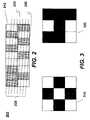
- FIG. 2A phenomena known as the loss of vertical synchronization 200 in scanning 2D bar-code symbols due to the limited height of elements is shown in FIG. 2 .
- a 2D bar-code 210is overlapped with a set of parallel scan lines 220 .
- the angle between scan line 220 and the horizontal axis of the bar-code 210is non-zero for a hand-held scanning device.
- certain scan lines 230cut across two rows of bar-code elements. As a result, these scan lines 230 are not useful. It would be desirable to have a method to decode the 2D bar-code avoiding the loss of synchronization problem. It would also be desirable to decode the 2D bar-code efficiently and effectively.
- the present inventionis related to processes, methods, systems and software products to encoding and decoding of a 2D bar-code.
- a new 2D bar-code symbologyis presented with at least the following features: 1) variable symbol width and height; 2) variable print resolution; 3) multiple damage protection levels; 4) large information storage; 5) high redundancy; 6) readable by line based scanning devices; and 7) recognizable by either contact scanning or non-contact scanning devices.
- a 2D bar-codecomprises a top border, a bottom border, a left border, a right border, a bit-stream data area and a plurality of data segment dividers.
- the unique pattern of the top and the bottom borderis used for guiding scanning device to recognize the orientation of a 2D bar-code, whether the bar-code is upside down or flipped mirror image.
- a plurality of corresponding pair of positioning holes on the left and the right borderare used for a scanning device to calculate the coordinates of data elements.
- the bit-stream data areacontains bar-code information in the form of ordered rows of 9-bit “codeword”, which has a data structure of 3 rows by 3 columns of data elements as shown in FIG. 3 . The order of bits is stored in row major from left to right, then top to bottom.
- the width and length of a 2D bar-codeis controlled by the amount of information carried in the bit-stream data area.
- a number of measures to protect against physical damageare employed in 2D bar-code.
- the first measureis to divide the data bit-stream into a number of equal size data segments.
- a set of data segment control informationis added to each data segment. As a result, redundancy is provided by repeating the critical control information related to the entire bar-code in each data segment.
- One of the measuresis to employ an industry standard error correction method (e g., Reed Solomon function) in each data segment. So even a portion of a bar-code is not recognizable, the error correction may be able to recreate the missing information with the error correction codeword located in the intact portion of the bar-code.
- error correction codewordlocated in the intact portion of the bar-code.
- a suitable level of error correctionmay be chosen. Ensuring higher confidence for decoding, an independent error correction scheme is employed for the data segment control information. Instead of storing codewords in sequential order, codewords are stored in an interleaved order, so the contiguous data is spread out in a larger area. As a result, the chance of damage to contiguous data decreases, while increasing the chance to recreate damage data via error correction.
- the scanning devicemay not catch the few white spaces in this concentration.
- a masking or bitwise-XOR operationis performed between the bit-stream of codeword data and a predefined mask to hide some of the concentrated bars.
- decoding methodsare also disclosed.
- One of the Methodsis used to decode the 2D bar-code after the entire 2D bar code symbol is scanned and stored.
- Another one of the methodsis used for decoding the 2D bar-code while the 2D bar-code is being scanned.
- these decoding methodsare incorporated as a software product loaded on a scanning device for decoding the 2D bar-code efficiently and effectively.
- a set of equally spaced parallel positioning linesis attached to a 2D bar-code. These positioning lines are used for guiding the scanning device to decode the 2D bar-code properly.
- the 2D bar-codemay be divided by visible marks corresponding to different paragraphs of an article.
- One of the objects, features, and advantages of the present inventionis to provide a symbology with flexible features and suitable for scanning.
- FIG. 1Ashows an example of a PDF 417 2D bar-code
- FIG. 1Billustrates an example of a QR Code.
- FIG. 2is a diagram illustrating the intersection of scan lines with rows of 2D bar-code elements.
- FIG. 3displays two examples of 9-bit code word from the present invention.
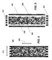
- FIG. 4is an example of a 2D bar-code from the present invention.
- FIG. 5is a dissected view of the 2D bar-code, in FIG. 4 .
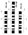
- FIGS. 6A–Cshow exemplary patterns of top border and bottom border.
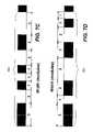
- FIG. 7A and 7Cdepict the details of two exemplary starting code of the top border.
- FIG. 7B and 7Ddepict the details of two exemplary ending code of the bottom border.
- FIG. 8is a table showing exemplary combinations between error correction codeword and data codeword at different error correction levels.
- FIG. 9Alists the interleaved storage scheme for a bit-stream of codeword data.
- FIG. 9Bshows one embodiment of the data structure of data segment control information.
- FIG. 9Cshows another embodiment of the data structure of data segment control information.
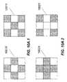
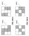
- FIGS. 10A.1 , 10 A. 2 , 10 A. 3 and 10 A. 4display four pairs of predefined mask patterns used in one embodiment of the present invention.
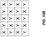
- FIG. 10Bshows an interleaf scheme similar to a chessboard for creating a predefined mask for a bar-code.
- FIG. 10Cshows an exemplary predefined mask.
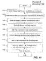
- FIG. 11shows a flow chart of a bar-code encoding method.
- FIG. 12Ashows a flow chart of a method to decode the 2D bar-code.
- FIGS. 12B and 12Cshow a flow chart of a method to decode the 2D-bar-code without the requirement of scanning the 2D bar-code symbol first.
- FIG. 13shows a detailed view of locating the positioning holes.
- FIG. 14Ashows a n alternative positioning teeth used with the 2D bar-code.
- FIGS. 14B and 14Cshow two exemplary of positioning lines attached to the 2D bar-code.
- FIG. 15shows a 2D bar-code with visible dividing marks corresponding to different paragraphs of an article encoded in it.
- FIG. 16depicts a detailed geometry to demonstrate how positioning lines guide the scanning device.
- FIGS. 17A and 17Bshow the relationship between adjacent positioning lines and consecutive scanning lines.
- FIG. 18shows a schematic chart of a scanner head corresponds to the 2D bar-code.
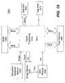
- FIG. 19shows a typical block diagram of a scanner.
- references herein to “one embodiment” or an “embodiment”means that a particular feature structure, or characteristic described in connection with the embodiment can be included in at least one embodiment of the invention.
- the appearances of the phrase “in one embodiment” in various places in the specificationare not necessarily all referring to the same embodiment, nor are separate or alternative embodiments mutually exclusive of other embodiments. Further, the order of blocks in process flowcharts or diagrams representing one or more embodiments of the invention do not inherently indicate any particular order nor imply any limitations in the invention.
- FIG. 3shows two examples of the data structure used in the 2D bar-code in the present invention.
- Each 9-bit codewordincludes data element arranged in 3 rows by 3 columns, each data element is either a dark colored or light colored. Each data element stores one bit of information. The order of the codeword is from left to right and top to bottom.
- the dark or light colored elementis referred to as a bar or a space.
- the barrepresents 1, and the space represents 0.
- the value of the codeword 310is 010101010 in binary or 0 ⁇ 0aa in hexadecimal
- the codeword 320is 101111001 in binary or 0 ⁇ 179 in hexadecimal.
- FIG. 4illustrates a rectangular 2D bar-code symbol 400 including a plurality of rectangular bar-code elements in bars and spaces.
- the rectangular bar-code symbol 400has two major axes horizontal axis 410 and vertical axis 420 .
- a dissected view of the 2D bar-code symbol 400is shown in FIG. 5 .
- the components of the 2D bar code symbol 400include a top border 510 , a bottom border 520 , a left border 530 , a right border 540 , a bit-stream data area 550 and a plurality of data segment dividers 560 .
- the 2D bar-code dataare stored in the form of bit-stream of codeword data.
- the bit-stream of codeword datacontains a set of ordered rows of 9-bit codeword.
- the bit-stream area 550is divided into a number of data segments separated by data segment dividers 560 .
- FIGS. 6A and 6BTwo exemplary top borders 510 are shown in FIGS. 6A and 6B .
- the top bordercomprises two basic components start code pattern 601 and terminator code pattern 605 .
- An exemplary top borderincludes two start code patterns 601 and one terminator code pattern 605 as shown in FIG. 6A .
- FIG. 6Bshows another exemplary top border that contains three start code patterns 601 .
- the number of start code pattern 601varies depending on the amount of data carried in the 2D bar-code.
- the minimum number of the start code pattern 601is one.
- the practical limitmay be controlled by the width of a carrier (e.g., the width of paper).
- the bottom border 520contains at one end code pattern 691 and one terminator code pattern 605 .
- An exemplary bottom block 520is illustrated in FIG. 6C .
- the terminator code pattern 605contains one 3-module wide bar.
- Both of the start code pattern 601 and the end code pattern 691are directional.
- the start code pattern 601has a construct of 6 alternated bars and spaces with a distinct combination of widths.
- the end code pattern 691has a similar construct with a different combination of widths.
- the width of the six componentsis as follows 3:1:1:2:2:2 modules for the start code pattern 601 as displayed in FIG. 7A .
- FIG. 7Bshows the width of the end code pattern 691 as follows: 3:2:2:1:1:2 modules for bars and spaces. Therefore, the total width of the bar-code is the sum of all the start/end code patterns and terminator code pattern.
- W11 *N +3 modules Where: W is the width of a bar-code; and
- Nis the number of repeating start/end code patterns in the bar-code.
- start code pattern and end code patternare illustrated in FIG. 7C and FIG. 7D .
- Theyare constructed by 8 alternated bars and spaces with a distinct combination of widths.
- the width of eight componentsis 3:2:1:1:1:2:2:3 modules for the start code pattern, which is displayed in FIG. 7C .
- FIG. 7Dshows the width ratio of the end code pattern as: 3:1:2.3:2:2:1:1 modules for bas and spaces.
- Nis the number of repeating start/end code patterns in the bar-code.
- each of the left border 530 and right border 540has an identical positioning block of a width of 3 modules and a length covering the height of the bar-code.
- the two outside columns of the borderare all bars and the middle column includes bars and spaces placed alternately in accordance with a predefined pattern.
- the patternis one bar to one space.
- the patterncan be a number of bars interlacing with a number of spaces. Inherently, the alternating spaces in the left and right borders are provided for locating the data elements in between.
- the bit-stream data area 550is divided into a number of equally sized data segments by a data segment divider 560 , which is one row of bars spanning the entire width of the bar-code.
- the Reed-Solomon error correction methodis applied against physical damages to the bar-code symbology.
- several optional choices of the Reed-Solomon schememay be employed to protect against damage of data elements.
- FIG. 8shows an exemplary list of different levels of Reed-Solomon scheme for 127-codeword data. It is evident that the higher the error correction level, the lower the amount of data can be stored in a given bar-code. Selecting a suitable option depends on the physical environment in which bar-code is deployed. Error correction codewords are calculated based on the level of error correction scheme selected.
- One method for reducing the probability of the loss of continuous datais as follows: a) to divide the data segment into a number of groups of fixed length data block (e.g., 127-codeword); b) to store multiple groups in an interleaved order so the continuous codewords are not stored next to each other.
- An exemplary scheme to store three groups of 127-codeword data in a round-robin fashionis illustrated in FIG. 9A .
- the number of groupscan be any positive numbers.
- FIG. 9Bshow one embodiment of the control information data structure. Due to the importance of these control data, a separate high level of error correction code is used independent of the error correction scheme employed for the codeword data. In FIG.
- bits e 0 to e 9represent the error correction code
- bits a 0 , a 1 , a 2 , a 3 and a 4represent the total number of data segments in the bar-code symbol
- bits, b 0 and b 1denote the selected error correction level
- the bit b 2denotes the interleaf toggle
- the bits, b 3 and b 4denote the mask type
- bits, c 0 to c 4represent the data segment number of the current data segment.
- FIG 9 Cshows another embodiment of the control information data structure.
- Bits A 3 , A 2 , A 1 , A 0 and B 3represent the data segment number of current data segment; bits, B 2 , B 1 , B 0 , C 3 and C 2 represent the total number of data segments in the bar-code, symbol; bits C 1 , C 0 , and C 3 denote the selected error correction level; bits D 2 and D 1 contain the mask type and bit D 0 is interleaf toggle.
- the control information dataare first arranged into seven 3 by 3 codeword, then converted into bit-stream. 3 remaining data elements are filled with 0. The control information is redundantly repeated in each data segment to ensure the availability of the information even if the bar-code goes through the toughest physical abuses.
- a schemeis to mask the bars by applying masking or bitwise-XOR operations to the bit-stream codeword data with a predefined mask.
- the masking mechanismis different from the conventional one. It it based on 3 rows by 3 columns codeword.
- a predefined maskis constructed using one of the four distinct pairs of masking codewords. Each pair contains a set of X and Y patterns.
- Each of the X an Y patternshas 3 rows and 3 columns of data elements, the same size as that of a codeword.
- they X patternis indicated in 1001 X and Y in 1001 Y.
- 1002 X and 1002 Yare the second pair
- 1003 X and 1003 Yare the third pair
- 1004 X and 1004 Yare the fourth pair as shown in FIGS. 10A.2 to 10 A. 4 .
- the X pattern and Y patternare placed in an interleaved order similar to a chessboard as illustrated in FIG. 10B .
- an exemplary predefined maskis constructed as shown in FIG. 10C .
- FIG. 11there shows a flowchart 1100 for encoding a 2D bar-code according to one embodiment of the present invention.
- a binary data fileis converted into a binary bit-stream of codeword at 1110 .
- error correction codewordsare calculated and then added into each bit-stream of codeword data (e.g, 127-codeword) at 1120 .
- a group of these bit-stream codeword datamay be stored in an interleaved order at 1130 .
- the entire bit-stream of codeword datais then divided into a number of data segments basing on the amount of information carried in the bar-code.
- the filler codewordsare appended to the last data segment if needed at 1150 .
- a masking or bitwise-XOR operationis applied on the bit-stream codeword data with a pre-selected mask to create a new bit-stream codeword of data.
- the control information for each data-segmentare first converted into codewords before added into the bit-stream of the data segment.
- a top border, a bottom border, a left border and a right borderare added.
- the 2D bar-codeis printed at 1190 .
- FIG. 12Ashows, a flowchart or process 1200 for decoding a 2D bar-code in entirety.
- the entire 2D bar-code symbolis scanned, stored in as a stored image, and then enhanced.
- the top and bottom bordersare detected and their corresponding coordinates are saved.
- the angle between the scan line and the horizontal axis of the bar-codeare determined.
- the stored bar-code image orientatione.g., upside down or inside out
- the first data segment divideris located in the stored image at 1220 .
- the coordinates of all data elements in the bit-stream data areaare calculated at 1225 .
- an error correction process on the control informationis performed to extract the vital control information such as error correction level, mask type, interleaf toggle, total number of data segments and current data segment numbers.
- the bit value (bar/space) of data elements in the bit-stream data areaare then read according to their coordinates calculated in 1225 and restored into a bit-stream of codeword data.
- the original bit-stream of codeword datais re-established with the operations of re-sequencing from an interleaved order, masking or bitwise-XOR, and error correction applying to the bit-stream created at 1235 .
- the bit-stream of codeword datais converted into the original binary data.
- FIGS. 12B and 12Ccollectively show a flowchart or process 1250 of decoding a 2D bar-code according to another embodiment of the present invention.
- the bar-codeis decoded while being scanned.
- the scanning devicescans a new line of a 2D bar-code into a scanned image and stores in a temporary storage.
- the scanned imageis compared with the bottom border pattern. If there is a match, the 2D bar-code image to be scanned is upside down. The decoding can only be done with the 2D bar-code image in entirety as described in FIG. 12A . Otherwise, at 1256 , the scanned image is compared with the top border pattern.
- step 1258is to determine whether the 2D bar-code is a mirror image. If it is a mirror image, the decoding can only be done with the method in FIG. 12A .
- step 1260the print resolution the 2D bar-code symbol is determined.
- scanning devicemoves on for another line of scanned image based on the printed solution.
- a testis to determine whether the scanned image is a data segment divider, which is a solid bar across the width of a 2D bar-code. If not, the process goes back to step 1262 for another new line of scanned image. Otherwise, the process starts to decode the bit-stream of codeword data carried in the 2D bar-code.
- the corresponding positioning holes of the left and right bordersare detected.
- a set of control informationis then read with the guide of the positioning holes and data segment divider at 1268 . Control information such as total number of data segments, error correction level, interleaf toggle, mask type and current segment number are extracted after error correction is operated on the control information portion of the bit-stream of codeword data.
- the testmakes sure that the correct data segment is being decoded while scanning. If not, the process goes to the process 1200 for decoding the 2D bar-code symbol in entirety.
- interleaved data storage orderis checked. Again, the decoding must be performed with the method for decoding the 2D bar-code in entirety if the bit-stream codeword of data is stored in interleaved order.
- one row of data elementsis read in. The process continues by testing whether the next line of scanned image is a data segment divider at step 1276 . If not, the process goes back to step at 1274 . Otherwise the original bit-stream codeword of data for the current data segment is finally restored after performing selected error correction at 1278 .
- a final testis performed. If the bottom border has not been detected in the next line of the scanned image, a new data segment is decoded with the repeating steps 1266 – 1280 . Otherwise, when bottom border is detected, the decoding is done.
- FIG. 13a detailed geometry is illustrated to show the procedure for determining the coordinates of data elements of a 2D bar-code using a corresponding pair of positioning holes in the left and right border of a stored 2D bar-code image.
- a data segment divider 1310is detected using four equally spaced vertical traces V 1 , V 2 , V 3 and V 4 in the vertical direction of the scanned image.
- the left border 1320is detected with for four equally spaced horizontal traces H 1 , H 2 , H 3 and H 4 in the horizontal direction of the scanned image.
- the right border 1330is detected with another set of four equally spaced horizontal traces H 5 , H 6 , H 7 and H 8 .
- FIG. 14Ashows a 2D bar code 1404 sandwiched between a pair of positioning teeth 1402 .
- These positioning teeth 1402are used for guiding scanning devices to correct image stretching and squeezing.
- the number of rows in a scanned imageis evenly distributed between the positioning teeth.
- the scanned imagemay be distorted due to the distance and angle between the scanning device and the 2D bar-code symbol.
- a scanned imagemay be stretched; there are more rows scanned between certain positioning teeth than others.
- the imagemay be squeezed; there are missing scanned rows between certain positioning teeth. Based on the fact of even distribution for all positioning teeth, some rows are deleted in the stretched area; additional rows are added by interpolating the adjacent scanned rows in the squeezed area.
- a set of positioning lines 1410are attached to the left side of a 2D bar-code 1420 .
- These positioning linescomprise a plurality of equally spaced parallel lines having a different slope than the horizontal axis of the 2D bar-code 1420 .
- the positioning linesmay be located at either side or both sides of a 2D bar-code symbol 1420 .
- FIG. 14Cshows the positioning lines 1430 are drawn on top of a 2D bar-code symbol 1440 with a different color used for the dark colored bars in the 2D bar-code.
- the decoding of the positioning lines and 2D bar-code data elementsare based on the reflection of the different scanning light color. For example, a 2D bar code uses blue colored bars and white colored spaces.
- the overlapping positioning linesmay be printed with a special black ink.
- scanning deviceuses a blue light source to scan the 2D bar-code symbol, both the bars and spaces would reflect the blue light while the black positioning line absorbs the blue light. Therefore, the positioning lines are read using the blue light source in a scanning device first before attempting to read the bar-code data with an infrared light source. That is because the infrared light goes through the special black ink, but the blue and the white color reflect distinctly.
- scanning devicesare able to read the bar-code data elements and the positioning lines in two different paths.
- a 2D bar-code 1510 with a plurality of visible physical division marks 1520 for separating information stored in the 2D bar-code 1510a 2D bar-code 1510 with a plurality of visible physical division marks 1520 for separating information stored in the 2D bar-code 1510 .
- each portion of the separated bar-codecorresponds to different paragraph of an article.
- FIG. 16depicts the geometry of positioning lines 1600 , a scan line 1620 and the horizontal axis 1610 of a 2D bar code.
- a set of parallel positioning lines 1600is intersected by the horizontal axis 1610 and by the scan line 1620 .
- the perpendicular distance 1640 between positioning lines 1600is denoted as D.
- the distance 1630 on the horizontal axis between two intersections with the positioning lines 1600is L.
- the distance 1650 on the scan line between two intersections with the positioning linesis n.
- the angle between the scan line 1620 and the bar-code horizontal line 1610is F.
- the angle between the horizontal axis 1610 and the positioning line 1600is E.
- the angle between the positioning line 1600 and the scan line 1620is G, which is the sum of E and F.
- Gar sin( D/n )
- FIGS. 17A and 17Bshow how scanning lines guide scanning devices.
- the resolution in a 2D bar-code's horizontal axis direction or x-directionis determined by the scanning device's resolution as x DPI.
- the resolutionis referred as y-resolution which is determined by the sampling rate of the scanning device as y DPI.
- the scannercompares two consecutive scan line images shown in FIGS. 17A and 17B .
- Two consecutive scan lines, line(A) and line(A+n)are shown in FIG. 17B .
- the corresponding imagesare plotted overlapping each other in FIG. 17A .
- Two crests pixel(B) and pixel(B+m)represent the intersections of one positioning line with two consecutive scan lines. Therefore, the distance between the crests is the distance between two scan lines as m pixels, is m*x, where x is the distance between two consecutive pixels.
- an exemplary CIS based scannerhas a 448 pixels wide scanning head.
- the mapping of the sensor to the 2D bar-code 400is as follows: 8-pixel to cover white spaces on either side of the bar-code; 12-pixel to cover the left border 530 and right 540 border; and 408 pixels for the bit-stream data area 550 .
- 408-pixelrepresents 102 data elements since each element is 4-pixel wide. That means 102 bits of information can be stored in one row of the bar-code 400 . In one embodiment, to store 127 codewords, 36-rows of data elements are required.
- a typical scanning device 1900comprises of a signal process chip 1910 , an image sensor 1920 , a document detection module 1930 , flash memory 1940 , ADC module 1950 , RAM 1960 , testing port 1970 and data port 1980 .
- the core of a scanning deviceis the signal processing chip 1910 whose main functions include: controlling all attaching modules; decoding binary bar-code data; storing the decoded information in RAM 1960 ; and outputting required data to data port 1980 .
- the image sensor 1920Basing on the clock and SP signal sending from signal processing chip 1910 , the image sensor 1920 catches the generated electric voltage (Vout) from the light reflected by a scanned image. The resulting digital data (Vin) is then sent back to signal processing chip 1910 .
- the document detection module 1930generates a “paper” signal when detecting a document is inserted.
- the signal processing chip 1910controls the start and end procedure of a scanning basing on this “paper” signal.
- the software used by the signal processing chip 1910is loaded into the flash memory 1940 .
- ADC module 1950converts the analogue data into digital data.
- the test port 1970is used for up loading software.
- the data port 1980is used for outputting the data from RAM 1960 to another computer.
Landscapes
- Engineering & Computer Science (AREA)
- Physics & Mathematics (AREA)
- Theoretical Computer Science (AREA)
- General Physics & Mathematics (AREA)
- General Health & Medical Sciences (AREA)
- Toxicology (AREA)
- Artificial Intelligence (AREA)
- Computer Vision & Pattern Recognition (AREA)
- Electromagnetism (AREA)
- Health & Medical Sciences (AREA)
- Error Detection And Correction (AREA)
- Image Processing (AREA)
- Image Input (AREA)
- Printers Characterized By Their Purpose (AREA)
Abstract
Description
W=11*N+3 modules
Where: W is the width of a bar-code; and
W=15*N+3 modules
Where: W is the width of a bar-code; and
Xp=(1/N)*Sum(Xi)
Yp=(1/N)*Sum(Yi)
where N is total number of, white pixel in the estimated area of positioning hole, Xi, Yi are the coordinates of white pixels in the estimated area of positioning hole.
F=90−E−arcos(D/n)
G=arsin(D/n)
V=(m*x)*tan(G)
When the y-direction distance V is equal to the sampling distance H, a new row of the scanned image is recorded. This process continues until the entire image has been scanned.
BL>=4*(Rp/Rs)pixels
where: BL is the minimum dimension of a 2D bar-code data element
- Rp is printer resolution
- Rs is scanner resolution
Claims (29)
Applications Claiming Priority (4)
| Application Number | Priority Date | Filing Date | Title |
|---|---|---|---|
| CN021345453.7 | 2002-08-07 | ||
| CN02134545ACN1396538A (en) | 2002-08-07 | 2002-08-07 | Method and system for electronizing character and chart information on ordinary carrier |
| CNB03117955XACN1294519C (en) | 2003-05-22 | 2003-05-22 | Two-D bar code encoding and decoding method |
| CN03117955.X | 2003-05-28 |
Publications (2)
| Publication Number | Publication Date |
|---|---|
| US20040026510A1 US20040026510A1 (en) | 2004-02-12 |
| US7028911B2true US7028911B2 (en) | 2006-04-18 |
Family
ID=31888900
Family Applications (2)
| Application Number | Title | Priority Date | Filing Date |
|---|---|---|---|
| US10/634,540Expired - LifetimeUS6802450B2 (en) | 2002-08-07 | 2003-08-05 | Guiding a scanning device to decode 2D symbols |
| US10/634,283Expired - LifetimeUS7028911B2 (en) | 2002-08-07 | 2003-08-05 | Methods and systems for encoding and decoding data in 2D symbology |
Family Applications Before (1)
| Application Number | Title | Priority Date | Filing Date |
|---|---|---|---|
| US10/634,540Expired - LifetimeUS6802450B2 (en) | 2002-08-07 | 2003-08-05 | Guiding a scanning device to decode 2D symbols |
Country Status (1)
| Country | Link |
|---|---|
| US (2) | US6802450B2 (en) |
Cited By (17)
| Publication number | Priority date | Publication date | Assignee | Title |
|---|---|---|---|---|
| US20040200904A1 (en)* | 2001-09-17 | 2004-10-14 | Mark Pinson | Machine-readable symbol and related method |
| US20060043186A1 (en)* | 2004-08-30 | 2006-03-02 | Nadabar Sateesha G | Methods and apparatus for reading bar code identifications |
| US20070145141A1 (en)* | 2005-12-22 | 2007-06-28 | Yuji Ayatsuka | Two-dimensional bar code, information processing device, information processing method, and program |
| US20080067257A1 (en)* | 2005-07-01 | 2008-03-20 | Norsk Elektro Optikk As | Marking and Reading System |
| US20080245869A1 (en)* | 2007-03-23 | 2008-10-09 | Ltt, Ltd | Method and apparatus for reading a printed indicia with a limited field of view sensor |
| US20090212111A1 (en)* | 2008-01-25 | 2009-08-27 | Intermec Ip Corp. | System and method for identifying erasures in a 2d symbol |
| US20090326836A1 (en)* | 2006-08-17 | 2009-12-31 | Gregory L Hovis | Two dimensional bar code having increased accuracy |
| WO2009016623A3 (en)* | 2007-07-29 | 2010-03-04 | Yonatan Yulevich | A code and a method for coding and encoding information |
| US20100072269A1 (en)* | 2008-09-24 | 2010-03-25 | Microsoft Corporation | Encoding, updating, and decoding barcodes in a document |
| US20100188710A1 (en)* | 2009-01-26 | 2010-07-29 | Xerox Corporation | Font-input based recognition engine for pattern fonts |
| US20110036909A1 (en)* | 2007-03-23 | 2011-02-17 | Labels That Talk, Ltd. | Method for reproducing and using a bar code symbol |
| WO2012085928A3 (en)* | 2010-12-15 | 2012-10-04 | Nallapa Reddy Ravi Kumar | Method of measuring length using new barcode symbology |
| US20140296755A1 (en)* | 2013-03-26 | 2014-10-02 | Hill-Rom Services, Inc. | Patient support with dynamic bar code generator |
| US8936194B1 (en) | 2013-03-15 | 2015-01-20 | Wunderlich-Malec Engineering, Inc. | Methods and systems for using two-dimensional matrix codes associated with panel component and equipment information and quality control |
| TWI505649B (en)* | 2012-04-05 | 2015-10-21 | Funcode Technology | System and method for encoding and decoding two dimensional barcode |
| CN105607881A (en)* | 2014-11-13 | 2016-05-25 | 卡西欧计算机株式会社 | Electronic device and two-dimensional code display method |
| US9734444B2 (en) | 2015-06-05 | 2017-08-15 | Empire Technology Development Llc | Solid-state barcodes and methods for their preparation and use |
Families Citing this family (61)
| Publication number | Priority date | Publication date | Assignee | Title |
|---|---|---|---|---|
| US6672511B1 (en)* | 1996-06-03 | 2004-01-06 | Symbol Technologies, Inc. | Omnidirectional reading of two-dimensional symbols |
| US20020016750A1 (en)* | 2000-06-20 | 2002-02-07 | Olivier Attia | System and method for scan-based input, storage and retrieval of information over an interactive communication network |
| US6666377B1 (en) | 2000-07-18 | 2003-12-23 | Scott C. Harris | Bar code data entry device |
| US6802450B2 (en)* | 2002-08-07 | 2004-10-12 | Shenzhen Syscan Technology Co. Ltd | Guiding a scanning device to decode 2D symbols |
| DE602004030434D1 (en)* | 2003-04-16 | 2011-01-20 | L 1 Secure Credentialing Inc | THREE-DIMENSIONAL DATA STORAGE |
| US7156311B2 (en)* | 2003-07-16 | 2007-01-02 | Scanbuy, Inc. | System and method for decoding and analyzing barcodes using a mobile device |
| US7387250B2 (en)* | 2003-12-04 | 2008-06-17 | Scanbuy, Inc. | System and method for on the spot purchasing by scanning barcodes from screens with a mobile device |
| US6814291B1 (en)* | 2003-12-15 | 2004-11-09 | Pitney Bowes Inc. | Robust barcode reader |
| US7296747B2 (en)* | 2004-04-20 | 2007-11-20 | Michael Rohs | Visual code system for camera-equipped mobile devices and applications thereof |
| US7309015B2 (en)* | 2004-07-14 | 2007-12-18 | Scanbuy, Inc. | Mobile device gateway providing access to instant information |
| US7578436B1 (en)* | 2004-11-08 | 2009-08-25 | Pisafe, Inc. | Method and apparatus for providing secure document distribution |
| US20070069028A1 (en)* | 2004-12-10 | 2007-03-29 | Yaron Nemet | System to improve reading performance and accuracy of single or two dimensional data codes in a large field of view |
| US7543748B2 (en)* | 2005-02-16 | 2009-06-09 | Pisafe, Inc. | Method and system for creating and using redundant and high capacity barcodes |
| US7568628B2 (en) | 2005-03-11 | 2009-08-04 | Hand Held Products, Inc. | Bar code reading device with global electronic shutter control |
| US7780089B2 (en) | 2005-06-03 | 2010-08-24 | Hand Held Products, Inc. | Digital picture taking optical reader having hybrid monochrome and color image sensor array |
| US7611060B2 (en) | 2005-03-11 | 2009-11-03 | Hand Held Products, Inc. | System and method to automatically focus an image reader |
| US8047440B2 (en)* | 2005-05-26 | 2011-11-01 | Symbol Technologies, Inc. | Method and system for decoding a barcode |
| US7770799B2 (en) | 2005-06-03 | 2010-08-10 | Hand Held Products, Inc. | Optical reader having reduced specular reflection read failures |
| US7571864B2 (en) | 2005-12-16 | 2009-08-11 | Pisafe, Inc. | Method and system for creating and using barcodes |
| WO2007089730A2 (en) | 2006-01-27 | 2007-08-09 | Spyder Lynk, Llc | Encoding and decoding data in an image |
| US8016187B2 (en) | 2006-02-21 | 2011-09-13 | Scanbury, Inc. | Mobile payment system using barcode capture |
| JP4899540B2 (en)* | 2006-03-08 | 2012-03-21 | 富士通株式会社 | Advertising service system |
| EP1845660B1 (en)* | 2006-04-12 | 2012-08-29 | STMicroelectronics Srl | Method for aggregating and transmitting sensor signals |
| US8150163B2 (en) | 2006-04-12 | 2012-04-03 | Scanbuy, Inc. | System and method for recovering image detail from multiple image frames in real-time |
| GB0613360D0 (en)* | 2006-07-05 | 2006-08-16 | Iti Scotland Ltd | Bar code authentication |
| US8459567B2 (en) | 2006-08-17 | 2013-06-11 | Direct Measurements, Inc. | Non-linear strain gage incorporating a nested binary code symbol |
| US8194914B1 (en) | 2006-10-19 | 2012-06-05 | Spyder Lynk, Llc | Encoding and decoding data into an image using identifiable marks and encoded elements |
| US20100020970A1 (en)* | 2006-11-13 | 2010-01-28 | Xu Liu | System And Method For Camera Imaging Data Channel |
| US8196836B2 (en)* | 2007-06-28 | 2012-06-12 | Fuji Xerox Co., Ltd. | Image processing apparatus, image processing method and computer-readable medium |
| GB2451437B (en)* | 2007-07-27 | 2012-11-14 | Hewlett Packard Development Co | Content encoder and decoder and methods of encoding and decoding content |
| GB2451434B (en)* | 2007-07-27 | 2012-09-19 | Hewlett Packard Development Co | A method of generating a sequence of display frames for display on a display device |
| US8427341B2 (en)* | 2007-07-29 | 2013-04-23 | Yonatan Yulevich | System and method for providing road information in advance |
| JP5014013B2 (en)* | 2007-08-02 | 2012-08-29 | 株式会社リコー | Image processing device |
| US9270420B2 (en)* | 2009-04-24 | 2016-02-23 | Samsung Electronics Co., Ltd. | Data communication using 2D bar codes |
| WO2010144087A1 (en)* | 2009-06-11 | 2010-12-16 | Hewlett-Packard Development Company, L.P. | Decoding a physical image |
| US8453921B2 (en)* | 2009-07-29 | 2013-06-04 | International Business Machines Corporation | Data transfers with bar codes |
| WO2012041967A1 (en) | 2010-10-01 | 2012-04-05 | Roche Diagnostics Gmbh | Apparatuses and methods for detecting optical barcodes |
| US8333326B2 (en)* | 2010-10-07 | 2012-12-18 | Nidec Sankyo Corporation | Stacked barcode reader and stacked barcode reading method |
| US8490877B2 (en)* | 2010-11-09 | 2013-07-23 | Metrologic Instruments, Inc. | Digital-imaging based code symbol reading system having finger-pointing triggered mode of operation |
| CN102810170B (en)* | 2011-06-02 | 2015-04-08 | 航天信息股份有限公司 | Quick response matrix code and building method thereof |
| US8297510B1 (en)* | 2011-06-30 | 2012-10-30 | Vladimir Yakshtes | Mathematical method of 2D barcode authentication and protection for embedded processing |
| US8615698B1 (en)* | 2011-09-28 | 2013-12-24 | Google Inc. | Skewed orthogonal coding techniques |
| TWI475494B (en)* | 2012-08-13 | 2015-03-01 | Univ Nat Cheng Kung | Method of read multiple two dimensional barcodes |
| US8770484B2 (en)* | 2012-09-21 | 2014-07-08 | Alcatel Lucent | Data exchange using streamed barcodes |
| US20140340423A1 (en)* | 2013-03-15 | 2014-11-20 | Nexref Technologies, Llc | Marker-based augmented reality (AR) display with inventory management |
| US9062999B2 (en)* | 2013-03-15 | 2015-06-23 | Catalina Marketing Corporation | System and method of encoding item information from a scale in a self-service scanning solution |
| US9042663B2 (en) | 2013-03-15 | 2015-05-26 | Pictech Management Limited | Two-level error correcting codes for color space encoded image |
| US9067671B2 (en) | 2013-07-25 | 2015-06-30 | Disney Enterprises, Inc. | Visual localization of unmanned aerial vehicles based on marker detection and processing |
| GB201314642D0 (en)* | 2013-08-15 | 2013-10-02 | Summerfield Gideon | Image Identification System and Method |
| US9037349B2 (en)* | 2013-08-27 | 2015-05-19 | Ford Global Technologies | Trailer identification system for trailer backup assist |
| CN107742146B (en)* | 2014-05-14 | 2020-12-22 | 共同印刷株式会社 | QR code analysis system |
| US9501681B1 (en)* | 2015-07-14 | 2016-11-22 | A9.Com, Inc. | Decoding visual codes |
| JP6952846B2 (en)* | 2015-12-04 | 2021-10-27 | 共同印刷株式会社 | Two-dimensional code |
| US9483718B1 (en) | 2015-12-14 | 2016-11-01 | International Business Machines Corporation | Encoding and decoding data in two-dimensional symbology |
| TWI564816B (en)* | 2015-12-29 | 2017-01-01 | 中強光電股份有限公司 | Electronic apparatus, an information transmitting method and an information reading method |
| JP6471835B2 (en)* | 2016-08-24 | 2019-02-20 | 日本電気株式会社 | Information processing apparatus, control method, and program |
| US10909432B2 (en)* | 2017-10-06 | 2021-02-02 | Denso Wave Incorporated | Two-dimensional code composed of a plurality of types of cells |
| US11660899B2 (en)* | 2017-11-07 | 2023-05-30 | Sumitomo Electric Sintered Alloy. Ltd. | Iron-based sintered body, method for laser-marking the same, and method for manufacturing the same |
| US11239988B2 (en)* | 2019-04-22 | 2022-02-01 | Texas Instruments Incorporated | Methods and systems for synchronization of slave device with master device |
| US11461571B2 (en) | 2020-02-13 | 2022-10-04 | United States Postal Service | System and method for reading a barcode independently of image resolution or scale |
| CN113487001B (en)* | 2021-09-08 | 2021-12-24 | 飞狐信息技术(天津)有限公司 | Two-dimensional code generation method and device and two-dimensional code identification method and device |
Citations (24)
| Publication number | Priority date | Publication date | Assignee | Title |
|---|---|---|---|---|
| US3632995A (en)* | 1968-05-09 | 1972-01-04 | Howard W Wilson | Coded article |
| US4896029A (en)* | 1988-04-08 | 1990-01-23 | United Parcel Service Of America, Inc. | Polygonal information encoding article, process and system |
| US4924078A (en)* | 1987-11-25 | 1990-05-08 | Sant Anselmo Carl | Identification symbol, system and method |
| US4999617A (en)* | 1985-10-24 | 1991-03-12 | Sharp Kabushiki Kaisha | Device for reading patterns displayed on a display unit |
| US5243655A (en)* | 1990-01-05 | 1993-09-07 | Symbol Technologies Inc. | System for encoding and decoding data in machine readable graphic form |
| US5329105A (en)* | 1992-08-10 | 1994-07-12 | United Parcel Service Of America, Inc. | Method and apparatus for determining the width of elements of bar code symbols |
| US5337362A (en)* | 1993-04-15 | 1994-08-09 | Ricoh Corporation | Method and apparatus for placing data onto plain paper |
| US5369265A (en)* | 1992-05-26 | 1994-11-29 | Olympus Optical Co., Ltd. | Bar-code reader apparatus with an automatic read starting function |
| US5378881A (en)* | 1992-05-29 | 1995-01-03 | Olympus Optical Co., Ltd. | Bar code reader for accurately reading two-dimensional bar code images |
| US5477042A (en)* | 1993-06-01 | 1995-12-19 | Metamedia Corporation | 2-D bar code scanner/decoder having a redundancy canceller |
| US5489769A (en)* | 1992-05-26 | 1996-02-06 | Olympus Optical Co., Ltd. | Symbol information reading apparatus |
| US5523552A (en)* | 1994-10-19 | 1996-06-04 | Symbol Technologies, Inc. | Method and apparatus to scan randomly oriented two-dimensional bar code symbols |
| US5591956A (en)* | 1995-05-15 | 1997-01-07 | Welch Allyn, Inc. | Two dimensional data encoding structure and symbology for use with optical readers |
| US5862270A (en)* | 1995-12-08 | 1999-01-19 | Matsushita Electric Industrial Co., Ltd. | Clock free two-dimensional barcode and method for printing and reading the same |
| US6082619A (en)* | 1998-12-16 | 2000-07-04 | Matsushita Electric Industrial Co., Ltd. | Method for locating and reading a two-dimensional barcode |
| US20020036704A1 (en)* | 2000-09-27 | 2002-03-28 | Hyung-Chul Kim | Method for providing variable bit rate in streaming service |
| US20020044689A1 (en)* | 1992-10-02 | 2002-04-18 | Alex Roustaei | Apparatus and method for global and local feature extraction from digital images |
| US20020088865A1 (en)* | 1998-01-28 | 2002-07-11 | Duanfeng He | Error correction in macro bar code symbols |
| US6456798B1 (en)* | 2000-08-09 | 2002-09-24 | Eastman Kodak Company | Barcode and data storage arrangement on a photographic element |
| US20030009725A1 (en)* | 2001-05-15 | 2003-01-09 | Sick Ag | Method of detecting two-dimensional codes |
| US6565003B1 (en)* | 1998-12-16 | 2003-05-20 | Matsushita Electric Industrial Co., Ltd. | Method for locating and reading a two-dimensional barcode |
| GB2388230A (en)* | 1998-12-16 | 2003-11-05 | Matsushita Electric Industrial Co Ltd | A method for locating and reading a barcode |
| JP2004070960A (en)* | 2002-08-07 | 2004-03-04 | Shenzhen Syscan Technology Co Ltd | Signaling method of two-dimensional barcode, scanner for performing the method, and decoding method |
| US6802450B2 (en)* | 2002-08-07 | 2004-10-12 | Shenzhen Syscan Technology Co. Ltd | Guiding a scanning device to decode 2D symbols |
Family Cites Families (13)
| Publication number | Priority date | Publication date | Assignee | Title |
|---|---|---|---|---|
| US5640001A (en)* | 1986-08-08 | 1997-06-17 | Norand Technology Corporation | Hand-held instant bar code reader having automatic focus control for operation over a range of distances |
| US5384451A (en)* | 1993-01-29 | 1995-01-24 | United Parcel Service Of America, Inc. | Method and apparatus for decoding bar code symbols using composite signals |
| US5304787A (en)* | 1993-06-01 | 1994-04-19 | Metamedia Corporation | Locating 2-D bar codes |
| US6543691B1 (en)* | 1995-01-03 | 2003-04-08 | Jerome H. Lemelson | Method and apparatus for encoding and decoding bar codes with primary and secondary information and method of using such bar codes |
| US5777309A (en)* | 1995-10-30 | 1998-07-07 | Intermec Corporation | Method and apparatus for locating and decoding machine-readable symbols |
| US5979761A (en)* | 1996-11-18 | 1999-11-09 | Accu-Sort Systems, Inc. | Bar code laser scanner having a plurality of adjustable mirrors |
| JP3557512B2 (en)* | 1997-12-03 | 2004-08-25 | ミヤチテクノス株式会社 | Laser marking method for 2D barcode |
| DE69810898T2 (en)* | 1998-05-20 | 2003-11-13 | Datalogic S.P.A., Lippo Di Calderara Di Reno | Method for restoring successive scans of a bar code |
| JP2000222517A (en)* | 1998-11-27 | 2000-08-11 | Denso Corp | Method and device for reading two-dimensional code, and recording medium |
| US6533181B1 (en)* | 2000-07-22 | 2003-03-18 | Roboric Vision Systems, Inc. | Direct marking of parts with encoded symbology method, apparatus and symbolody |
| EP1182604A1 (en)* | 2000-08-22 | 2002-02-27 | Setrix AG | Method and apparatus for reading a bar code |
| US6814289B2 (en)* | 2001-05-30 | 2004-11-09 | Sandia Corporation | Self-registering spread-spectrum barcode method |
| WO2004006438A2 (en)* | 2002-07-08 | 2004-01-15 | Veritec, Inc. | Method for reading a symbol having encoded information |
- 2003
- 2003-08-05USUS10/634,540patent/US6802450B2/ennot_activeExpired - Lifetime
- 2003-08-05USUS10/634,283patent/US7028911B2/ennot_activeExpired - Lifetime
Patent Citations (26)
| Publication number | Priority date | Publication date | Assignee | Title |
|---|---|---|---|---|
| US3632995A (en)* | 1968-05-09 | 1972-01-04 | Howard W Wilson | Coded article |
| US4999617A (en)* | 1985-10-24 | 1991-03-12 | Sharp Kabushiki Kaisha | Device for reading patterns displayed on a display unit |
| US5612524A (en)* | 1987-11-25 | 1997-03-18 | Veritec Inc. | Identification symbol system and method with orientation mechanism |
| US4924078A (en)* | 1987-11-25 | 1990-05-08 | Sant Anselmo Carl | Identification symbol, system and method |
| US4896029A (en)* | 1988-04-08 | 1990-01-23 | United Parcel Service Of America, Inc. | Polygonal information encoding article, process and system |
| US5243655A (en)* | 1990-01-05 | 1993-09-07 | Symbol Technologies Inc. | System for encoding and decoding data in machine readable graphic form |
| US5369265A (en)* | 1992-05-26 | 1994-11-29 | Olympus Optical Co., Ltd. | Bar-code reader apparatus with an automatic read starting function |
| US5489769A (en)* | 1992-05-26 | 1996-02-06 | Olympus Optical Co., Ltd. | Symbol information reading apparatus |
| US5378881A (en)* | 1992-05-29 | 1995-01-03 | Olympus Optical Co., Ltd. | Bar code reader for accurately reading two-dimensional bar code images |
| US5329105A (en)* | 1992-08-10 | 1994-07-12 | United Parcel Service Of America, Inc. | Method and apparatus for determining the width of elements of bar code symbols |
| US20020044689A1 (en)* | 1992-10-02 | 2002-04-18 | Alex Roustaei | Apparatus and method for global and local feature extraction from digital images |
| US5337362A (en)* | 1993-04-15 | 1994-08-09 | Ricoh Corporation | Method and apparatus for placing data onto plain paper |
| US5477042A (en)* | 1993-06-01 | 1995-12-19 | Metamedia Corporation | 2-D bar code scanner/decoder having a redundancy canceller |
| US5523552A (en)* | 1994-10-19 | 1996-06-04 | Symbol Technologies, Inc. | Method and apparatus to scan randomly oriented two-dimensional bar code symbols |
| US5591956A (en)* | 1995-05-15 | 1997-01-07 | Welch Allyn, Inc. | Two dimensional data encoding structure and symbology for use with optical readers |
| US5862270A (en)* | 1995-12-08 | 1999-01-19 | Matsushita Electric Industrial Co., Ltd. | Clock free two-dimensional barcode and method for printing and reading the same |
| US6115508A (en)* | 1995-12-08 | 2000-09-05 | Matsushita Electric Industrial Co., Ltd. | Clock free two-dimensional barcode and method for printing and reading the same |
| US20020088865A1 (en)* | 1998-01-28 | 2002-07-11 | Duanfeng He | Error correction in macro bar code symbols |
| US6082619A (en)* | 1998-12-16 | 2000-07-04 | Matsushita Electric Industrial Co., Ltd. | Method for locating and reading a two-dimensional barcode |
| US6565003B1 (en)* | 1998-12-16 | 2003-05-20 | Matsushita Electric Industrial Co., Ltd. | Method for locating and reading a two-dimensional barcode |
| GB2388230A (en)* | 1998-12-16 | 2003-11-05 | Matsushita Electric Industrial Co Ltd | A method for locating and reading a barcode |
| US6456798B1 (en)* | 2000-08-09 | 2002-09-24 | Eastman Kodak Company | Barcode and data storage arrangement on a photographic element |
| US20020036704A1 (en)* | 2000-09-27 | 2002-03-28 | Hyung-Chul Kim | Method for providing variable bit rate in streaming service |
| US20030009725A1 (en)* | 2001-05-15 | 2003-01-09 | Sick Ag | Method of detecting two-dimensional codes |
| JP2004070960A (en)* | 2002-08-07 | 2004-03-04 | Shenzhen Syscan Technology Co Ltd | Signaling method of two-dimensional barcode, scanner for performing the method, and decoding method |
| US6802450B2 (en)* | 2002-08-07 | 2004-10-12 | Shenzhen Syscan Technology Co. Ltd | Guiding a scanning device to decode 2D symbols |
Cited By (31)
| Publication number | Priority date | Publication date | Assignee | Title |
|---|---|---|---|---|
| US7188778B2 (en)* | 2001-09-17 | 2007-03-13 | Codemagic | Machine-readable symbol and related method |
| US20040200904A1 (en)* | 2001-09-17 | 2004-10-14 | Mark Pinson | Machine-readable symbol and related method |
| US7427028B2 (en) | 2004-08-30 | 2008-09-23 | Cognex Corporation | Methods and apparatus for reading bar code identifications |
| US20060043186A1 (en)* | 2004-08-30 | 2006-03-02 | Nadabar Sateesha G | Methods and apparatus for reading bar code identifications |
| US7175090B2 (en) | 2004-08-30 | 2007-02-13 | Cognex Technology And Investment Corporation | Methods and apparatus for reading bar code identifications |
| WO2006026594A3 (en)* | 2004-08-30 | 2007-03-01 | Cognex Corp | Methods and apparatus for reading bar code identifications |
| US20080067257A1 (en)* | 2005-07-01 | 2008-03-20 | Norsk Elektro Optikk As | Marking and Reading System |
| US7857232B2 (en)* | 2005-12-22 | 2010-12-28 | Sony Corporation | Two-dimensional bar code, information processing device, information processing method, and program |
| US20070145141A1 (en)* | 2005-12-22 | 2007-06-28 | Yuji Ayatsuka | Two-dimensional bar code, information processing device, information processing method, and program |
| US20090326836A1 (en)* | 2006-08-17 | 2009-12-31 | Gregory L Hovis | Two dimensional bar code having increased accuracy |
| US8366011B2 (en) | 2006-08-17 | 2013-02-05 | Direct Measurements, Inc. | Two dimensional bar code having increased accuracy |
| US8662396B2 (en) | 2007-03-23 | 2014-03-04 | Labels That Talk, Ltd | Method for reproducing and using a bar code symbol |
| US20080245869A1 (en)* | 2007-03-23 | 2008-10-09 | Ltt, Ltd | Method and apparatus for reading a printed indicia with a limited field of view sensor |
| US20110036909A1 (en)* | 2007-03-23 | 2011-02-17 | Labels That Talk, Ltd. | Method for reproducing and using a bar code symbol |
| WO2009016623A3 (en)* | 2007-07-29 | 2010-03-04 | Yonatan Yulevich | A code and a method for coding and encoding information |
| US20090212111A1 (en)* | 2008-01-25 | 2009-08-27 | Intermec Ip Corp. | System and method for identifying erasures in a 2d symbol |
| US8162222B2 (en)* | 2008-01-25 | 2012-04-24 | Intermec Ip Corp. | System and method for identifying erasures in a 2D symbol |
| US20100072269A1 (en)* | 2008-09-24 | 2010-03-25 | Microsoft Corporation | Encoding, updating, and decoding barcodes in a document |
| US8925822B2 (en) | 2008-09-24 | 2015-01-06 | Microsoft Corporation | Encoding, updating, and decoding barcodes in a document |
| US20100188710A1 (en)* | 2009-01-26 | 2010-07-29 | Xerox Corporation | Font-input based recognition engine for pattern fonts |
| WO2012085928A3 (en)* | 2010-12-15 | 2012-10-04 | Nallapa Reddy Ravi Kumar | Method of measuring length using new barcode symbology |
| TWI505649B (en)* | 2012-04-05 | 2015-10-21 | Funcode Technology | System and method for encoding and decoding two dimensional barcode |
| US8936194B1 (en) | 2013-03-15 | 2015-01-20 | Wunderlich-Malec Engineering, Inc. | Methods and systems for using two-dimensional matrix codes associated with panel component and equipment information and quality control |
| US9047279B1 (en) | 2013-03-15 | 2015-06-02 | Wunderlich-Malec Engineering, Inc. | Methods and systems for using two-dimensional matrix codes associated with panel component and equipment information and quality control |
| US20140296755A1 (en)* | 2013-03-26 | 2014-10-02 | Hill-Rom Services, Inc. | Patient support with dynamic bar code generator |
| US10026505B2 (en)* | 2013-03-26 | 2018-07-17 | Hill-Rom Services, Inc. | Patient support with dynamic bar code generator |
| CN105607881A (en)* | 2014-11-13 | 2016-05-25 | 卡西欧计算机株式会社 | Electronic device and two-dimensional code display method |
| US9412057B2 (en)* | 2014-11-13 | 2016-08-09 | Casio Computer Co., Ltd. | Electronic device, method of displaying two-dimensional code, and recording medium with program recorded thereon |
| CN105607881B (en)* | 2014-11-13 | 2018-11-30 | 卡西欧计算机株式会社 | Electronic equipment and two-dimensional code display method |
| CN109376110A (en)* | 2014-11-13 | 2019-02-22 | 卡西欧计算机株式会社 | Electronic device, two-dimensional code display method, and recording medium |
| US9734444B2 (en) | 2015-06-05 | 2017-08-15 | Empire Technology Development Llc | Solid-state barcodes and methods for their preparation and use |
Also Published As
| Publication number | Publication date |
|---|---|
| US20040026511A1 (en) | 2004-02-12 |
| US20040026510A1 (en) | 2004-02-12 |
| US6802450B2 (en) | 2004-10-12 |
Similar Documents
| Publication | Publication Date | Title |
|---|---|---|
| US7028911B2 (en) | Methods and systems for encoding and decoding data in 2D symbology | |
| KR100960786B1 (en) | Encoding Decoding Method and System of 2D Code | |
| EP1016027B1 (en) | Distortion resistant double-data correcting color transition barcode and method of generating and using same | |
| KR100414524B1 (en) | Two-dimensional Code having superior decoding property which is possible to control the level of error correcting codes, and method for encoding and decoding the same | |
| US8006911B2 (en) | System and method for encoding and decoding large capacity 2-dimensional color bar code which can be color-corrected | |
| TW412709B (en) | Encoded color halftone micro-dots for high density digital information storage | |
| US7543748B2 (en) | Method and system for creating and using redundant and high capacity barcodes | |
| EP2178031B1 (en) | Optical code recognition apparatus, optical code and recognition method. | |
| US6685095B2 (en) | Apparatus and method for decoding damaged optical codes | |
| EP2122534B1 (en) | Multiple resolution readable color array | |
| EP2248068B1 (en) | Two-dimensional symbol and method for reading same | |
| AU701214B2 (en) | Packet bar code encoding and decoding | |
| JPH03204793A (en) | Non volatile electrooptic type read -only memory in high-density two- dimensional symbolic display method | |
| KR20090018811A (en) | Multidimensional Symbols and Related Methods | |
| KR20060076160A (en) | System and method for encoding high density geometric symbol sets | |
| JP6860355B2 (en) | Improved matrix symbol error correction method | |
| US20060289661A1 (en) | Bi-directional readable two-dimensional bar code system and its reading method | |
| KR20030085511A (en) | 2d barcode card and its decoding method | |
| US12346756B2 (en) | Two-dimensional barcode, method and system for encoding data into said two-dimensional barcode, and method and system for imaging and decoding said two-dimensional barcode | |
| CN1770177A (en) | System and method for encoding high density geometric symbol set | |
| JP4155156B2 (en) | Bar code reader and bar code discrimination method |
Legal Events
| Date | Code | Title | Description |
|---|---|---|---|
| AS | Assignment | Owner name:SYSCAN INC., CALIFORNIA Free format text:ASSIGNMENT OF ASSIGNORS INTEREST;ASSIGNORS:CHEUNG, WAI;CHANG, ZHI-QUO;DING, SHILING;AND OTHERS;REEL/FRAME:014374/0457;SIGNING DATES FROM 20030801 TO 20030804 Owner name:SHENZHEN SYSCAN TECHNOLOGY CO., LIMITED, CHINA Free format text:ASSIGNMENT OF ASSIGNORS INTEREST;ASSIGNORS:CHEUNG, WAI;CHANG, ZHI-QUO;DING, SHILING;AND OTHERS;REEL/FRAME:014374/0457;SIGNING DATES FROM 20030801 TO 20030804 | |
| STCF | Information on status: patent grant | Free format text:PATENTED CASE | |
| AS | Assignment | Owner name:BANKENGINE TECHNOLOGIES INC., CANADA Free format text:ACQUISITION OF SYSCAN, INC. BY BANKENGINE TECHNOLOGIES INC.;ASSIGNOR:SYSCAN, INC.;REEL/FRAME:021861/0718 Effective date:20040329 | |
| AS | Assignment | Owner name:SYSCAN IMAGING, INC., CALIFORNIA Free format text:CHANGE OF NAME;ASSIGNOR:BANKENGINE TECHNOLOGIES INC.;REEL/FRAME:021890/0356 Effective date:20040402 | |
| AS | Assignment | Owner name:SYSVIEW TECHNOLOGY, INC., CALIFORNIA Free format text:CHANGE OF NAME;ASSIGNOR:SYSCAN IMAGING, INC.;REEL/FRAME:021890/0957 Effective date:20060627 | |
| AS | Assignment | Owner name:DOCUMENT CAPTURE TECHNOLOGIES, INC., CALIFORNIA Free format text:MERGER;ASSIGNOR:SYSVIEW TECHNOLOGY, INC.;REEL/FRAME:021901/0099 Effective date:20071226 | |
| FPAY | Fee payment | Year of fee payment:4 | |
| AS | Assignment | Owner name:SHANGHAI SYSCAN INFORMATION TECHNOLOGY CO., LTD., Free format text:ASSIGNMENT OF ASSIGNORS INTEREST;ASSIGNOR:SHENZHEN SYSCAN TECHNOLOGY CO. LIMITED;REEL/FRAME:029615/0351 Effective date:20121206 | |
| FPAY | Fee payment | Year of fee payment:8 | |
| AS | Assignment | Owner name:WUHAN SYSCAN TECHNOLOGY CO., LTD, CHINA Free format text:ASSIGNMENT OF ASSIGNORS INTEREST;ASSIGNOR:SHENZHEN SYSCAN TECHNOLOGY CO., LTD.;REEL/FRAME:033793/0503 Effective date:20140803 | |
| FPAY | Fee payment | Year of fee payment:12 |