US7028634B1 - Worklight with thermal warning - Google Patents
Worklight with thermal warningDownload PDFInfo
- Publication number
- US7028634B1 US7028634B1US09/891,484US89148401AUS7028634B1US 7028634 B1US7028634 B1US 7028634B1US 89148401 AUS89148401 AUS 89148401AUS 7028634 B1US7028634 B1US 7028634B1
- Authority
- US
- United States
- Prior art keywords
- worklight
- bezel
- coating composition
- thermochromic
- warning
- Prior art date
- Legal status (The legal status is an assumption and is not a legal conclusion. Google has not performed a legal analysis and makes no representation as to the accuracy of the status listed.)
- Expired - Lifetime, expires
Links
- 230000008859changeEffects0.000claimsabstractdescription27
- 229910052736halogenInorganic materials0.000claimsabstractdescription15
- 150000002367halogensChemical class0.000claimsabstractdescription15
- 230000031070response to heatEffects0.000claimsabstractdescription8
- 238000004891communicationMethods0.000claimsabstractdescription6
- 239000000758substrateSubstances0.000claimsdescription16
- 239000008199coating compositionSubstances0.000claimsdescription15
- 230000004044responseEffects0.000claims2
- 239000000126substanceSubstances0.000abstractdescription33
- 239000010453quartzSubstances0.000abstractdescription9
- VYPSYNLAJGMNEJ-UHFFFAOYSA-Nsilicon dioxideInorganic materialsO=[Si]=OVYPSYNLAJGMNEJ-UHFFFAOYSA-N0.000abstractdescription9
- 230000007246mechanismEffects0.000abstractdescription2
- 230000000007visual effectEffects0.000abstract1
- 239000010410layerSubstances0.000description23
- 230000004913activationEffects0.000description14
- 239000000976inkSubstances0.000description11
- 239000000463materialSubstances0.000description11
- 230000001681protective effectEffects0.000description11
- 239000000203mixtureSubstances0.000description9
- 238000013461designMethods0.000description7
- 238000009472formulationMethods0.000description7
- 239000003973paintSubstances0.000description5
- 239000012790adhesive layerSubstances0.000description4
- 230000008901benefitEffects0.000description4
- 230000006378damageEffects0.000description4
- 230000007704transitionEffects0.000description4
- 238000010276constructionMethods0.000description3
- 238000012546transferMethods0.000description3
- 206010037867Rash macularDiseases0.000description2
- 208000027418Wounds and injuryDiseases0.000description2
- 230000015556catabolic processEffects0.000description2
- 239000003086colorantSubstances0.000description2
- 238000001816coolingMethods0.000description2
- 238000006731degradation reactionMethods0.000description2
- 239000011521glassSubstances0.000description2
- 238000010438heat treatmentMethods0.000description2
- 208000014674injuryDiseases0.000description2
- 238000004519manufacturing processMethods0.000description2
- 239000002184metalSubstances0.000description2
- 229910052751metalInorganic materials0.000description2
- 150000002739metalsChemical class0.000description2
- 239000004033plasticSubstances0.000description2
- 229920003023plasticPolymers0.000description2
- -1polypropylenePolymers0.000description2
- 230000002441reversible effectEffects0.000description2
- 239000012780transparent materialSubstances0.000description2
- 229910001369BrassInorganic materials0.000description1
- 241000196324EmbryophytaSpecies0.000description1
- 239000004593EpoxySubstances0.000description1
- 241001427367GardenaSpecies0.000description1
- 239000004698PolyethyleneSubstances0.000description1
- 239000004743PolypropyleneSubstances0.000description1
- 239000004793PolystyreneSubstances0.000description1
- FAPWRFPIFSIZLT-UHFFFAOYSA-MSodium chlorideChemical compound[Na+].[Cl-]FAPWRFPIFSIZLT-UHFFFAOYSA-M0.000description1
- 238000005299abrasionMethods0.000description1
- 229920000122acrylonitrile butadiene styrenePolymers0.000description1
- 239000004676acrylonitrile butadiene styreneSubstances0.000description1
- 239000000853adhesiveSubstances0.000description1
- 230000001070adhesive effectEffects0.000description1
- 239000000443aerosolSubstances0.000description1
- 238000013459approachMethods0.000description1
- 239000007767bonding agentSubstances0.000description1
- 239000010951brassSubstances0.000description1
- 239000003795chemical substances by applicationSubstances0.000description1
- 230000007423decreaseEffects0.000description1
- 230000000694effectsEffects0.000description1
- 230000007613environmental effectEffects0.000description1
- 239000004519greaseSubstances0.000description1
- 231100001261hazardousToxicity0.000description1
- 238000005286illuminationMethods0.000description1
- 238000009413insulationMethods0.000description1
- 239000004973liquid crystal related substanceSubstances0.000description1
- 238000000034methodMethods0.000description1
- 238000012986modificationMethods0.000description1
- 230000004048modificationEffects0.000description1
- 230000008520organizationEffects0.000description1
- 238000005192partitionMethods0.000description1
- 229920000573polyethylenePolymers0.000description1
- 229920001155polypropylenePolymers0.000description1
- 229920002223polystyrenePolymers0.000description1
- 229920000915polyvinyl chloridePolymers0.000description1
- 239000004800polyvinyl chlorideSubstances0.000description1
- 235000019633pungent tasteNutrition0.000description1
- 230000005855radiationEffects0.000description1
- 230000008439repair processEffects0.000description1
- 230000006903response to temperatureEffects0.000description1
- 238000006748scratchingMethods0.000description1
- 230000002393scratching effectEffects0.000description1
- 235000002639sodium chlorideNutrition0.000description1
- 239000011780sodium chlorideSubstances0.000description1
- 238000003466weldingMethods0.000description1
Images


Classifications
- G—PHYSICS
- G01—MEASURING; TESTING
- G01D—MEASURING NOT SPECIALLY ADAPTED FOR A SPECIFIC VARIABLE; ARRANGEMENTS FOR MEASURING TWO OR MORE VARIABLES NOT COVERED IN A SINGLE OTHER SUBCLASS; TARIFF METERING APPARATUS; MEASURING OR TESTING NOT OTHERWISE PROVIDED FOR
- G01D7/00—Indicating measured values
- G01D7/005—Indication of measured value by colour change
- F—MECHANICAL ENGINEERING; LIGHTING; HEATING; WEAPONS; BLASTING
- F21—LIGHTING
- F21L—LIGHTING DEVICES OR SYSTEMS THEREOF, BEING PORTABLE OR SPECIALLY ADAPTED FOR TRANSPORTATION
- F21L14/00—Electric lighting devices without a self-contained power source, e.g. for mains connection
- F—MECHANICAL ENGINEERING; LIGHTING; HEATING; WEAPONS; BLASTING
- F21—LIGHTING
- F21V—FUNCTIONAL FEATURES OR DETAILS OF LIGHTING DEVICES OR SYSTEMS THEREOF; STRUCTURAL COMBINATIONS OF LIGHTING DEVICES WITH OTHER ARTICLES, NOT OTHERWISE PROVIDED FOR
- F21V15/00—Protecting lighting devices from damage
- F21V15/02—Cages
Definitions
- the present inventionrelates to worklights such as quartz halogen worklights that operate at a comparatively hot temperature.
- Quartz halogen worklightsare used in a variety of settings such as construction sites, industrial plants, automotive and auto body repair shops, artist and photographic studios, and around the home for do-it-yourself projects. These lights provide a high level of illumination over an extended area.
- the quartz halogen bulbshowever, have a comparatively high operating temperature, and consequently the exterior surfaces of the worklights tend to get hot.
- Some worklight manufacturersapply a printed label to a prominent surface of the worklight warning of a potential risk of fire or injury and warning to keep the unit away from combustibles; others additionally print a “hot surface” reminder warning on the label; yet others give no specific warning at all and rely instead on the general astuteness of the user to recognize and appreciate the inherent hotness of the worklight surfaces during and for a short duration following use.
- a worklight incorporating the inventiontypically has a housing that includes an interior portion for holding a light source such as one or more quartz halogen bulbs.
- the light sourceoperates at a temperature sufficient to raise at least portions of the exterior surfaces of the housing to a temperature that is hot to human touch during normal operation of the worklight.
- the inventionincludes a thermochromic substance in thermal communication with at least a portion of one of the exterior housing surfaces in a readily visible position.
- the thermochromic substanceis formulated to undergo a conspicuous color change, in the normal operation of the worklight, in response to heat from the external surface where it is located.
- the dynamic color changeprovides a timely visible indication to the user that the exterior surface is presently hot to the touch.
- thermochromic layersuch as a band of thermochromic ink is applied to the underside of a transparent substrate.
- Warning indiciasuch as a cautionary legend or symbol, are printed in non-thermochromic ink on the underside of the thermochromic layer.
- the substrateis then adhered to a thermal moderator material and the assembly is secured to the worklight surface.
- the thermochromic layeris opaque and obscures the cautionary warning.
- heatis conducted through the thermal moderator material to the thermochromic layer, which turns transparent to reveal the cautionary warning.
- the thermal moderator in this embodimentenables the use of thermochromic inks of lower activation temperature and provides for more uniform color change over the thermochromic layer.
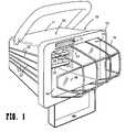
- FIG. 1is a perspective view of a worklight showing a thermal warning arrangement according to the invention.
- FIGS. 2A and 2Bare exploded views of alternative embodiments of the thermal warning arrangement of FIG. 1 .
- the worklightillustrated in FIG. 1 , is formed with a housing 10 , which has a body portion 11 and a front bezel 12 defining a front exit window 13 .
- the exit windowis covered by a protective glass shield 14 , in front of which extends a protective grill 16 .
- the housingincludes an interior portion formed by interior sidewall 17 , bottom wall 18 , back wall 19 and the opposing side and top walls, which are not visible in FIG. 1 .
- the interior portionholds a light source, which in the embodiment of FIG. 1 is provided by a pair of tubular quartz halogen bulbs 21 . These bulbs commonly have a power rating of 250 to 300 Watts each so that the worklight has a total rating of 500 to 600 Watts. In the normal operation of the worklight these bulbs generate a significant amount of heat.
- Worklights such as thistypically include specific measures for handling the excess heat. These may include for example minimum bulb clearances, baffles or partitions about the bulbs, cooling structures on the worklight body (such as the cooling vanes 22 visible on an exterior side wall of the worklight in FIG. 1 ), thermal vents in the light-bulb chamber or other regions of the worklight body, choice of materials for the walls defining the light-bulb chamber, and even the use of thermal insulation. Notwithstanding these measures, however, the exterior housing surfaces tend to become hot during the normal operation of the light. The generation of excess heat is a common enough occurrence in worklight designs that as a precaution against damage or injury, at least one major safety-certification organization requires that during normal worklight operation no exterior surface attain a temperature hotter than a prescribed maximum level.
- Thermal warning indicator 23is formed of a thermochromic substance disposed on the worklight so that it is in thermal communication with at least a portion of an exterior surface.
- the thermochromic substanceis formulated to undergo a conspicuous color change in response to heat from the exterior surface during normal operation of the worklight at an activation temperature indicating that the exterior surface is of a temperature that is hot to the touch or that is otherwise potentially hazardous.
- thermochromicrefers to the reversible capacity to change color in response to temperatures at or above an activation temperature.
- Color changeis understood in a broad sense to include not only changes in hue, saturation and intensity, but also changes in opacity, and may include for example a change between completely opaque and completely clear.
- the capacity to change coloris reversible in the sense that the color returns to its initial color when the temperature returns to its initial, subactivation level.
- the characteristic color changewill generally occur as the temperature varies over a transition range beginning at the activation temperature.
- the color changemay take place quickly over a narrow transition range or more gradually over a broader transition range, just so long as the transition provides an effective indication that the surface is hot.
- thermochromic materialsare available from a number of commercial suppliers. These are typically available in the form of heat-activated inks, paints or other coating compositions that change colors or disappear when they exceed a predetermined activation temperature, then change back when the temperature decreases below that same activation temperature.
- Thermochromic substancesalso include certain liquid crystal compositions but these tend to be more expensive and have lower color density and reduced selectivity in color or activation temperature, and so the thermochromic inks or coating compositions are generally preferred.
- thermochromic compositionsare described in U.S. Pat. No. 4,717,710 to Shimizu et al.; U.S. Pat. No. 4,957,949 to Kamada et al. and U.S. Pat. No. 5,431,697 to Kamata et al., and one commercial source of thermochromic substances is Matsui International Company, Inc. of Gardena, Calif., which provides a selection of thermochromic inks as well as thermochromic paints for a variety of plastics and metals, including die cast metals, brass, ABS, polystyrene, polypropylene, polyethylene, PVC and other substrates.
- the thermochromic substances of the present inventionare not intended to be limited only to those available from Matsui International Company. Rather, any number of commercially available thermochromic substances having activation temperatures within the desired temperature range may be used.
- thermal warning indicator 23is positioned on the front bezel 12 although it could also be positioned on another surface such as the top surface 24 .
- the indicatorshould be disposed in a readily visible location so as to give conspicuous warning to the user or others.
- FIG. 2Ashows a first implementation of thermal warning indicator 23 .
- a protective covering 26 of a transparent materialOn top is a protective covering 26 of a transparent material.
- the transparent materialFor the greatest visibility it is desirable that the transparent material be completely clear, although in some designs it may be desirable for the material to take on a slight tint or opacity for aesthetic purposes.
- the thermochromic substancetakes the form of a thermochromic layer 27 coated on the underside of covering 26 , which serves here as a substrate for carrying the thermochromic substance.
- Thermochromic layer 27may, for example, simply be a band of thermochromic ink printed on the underside, that is, the backside, of substrate 26 .
- Warning indicia 28are printed, in turn, on the underside of thermochromic layer 27 in a non-thermochromic substance.
- the warning indiciamay take any form but will typically comprise cautionary words such as “hot surface” or “caution” and may also comprise a graphic symbol or design.
- a thermal moderator 29is interposed between the thermochromic layer and the underlying worklight surface 31 .
- Surface 31is formed with a recessed area 32 for receiving covering 26 .
- the recessed areais formed so that covering 26 lies substantially flush with surface 31 when cemented or otherwise secured in position in the recessed area.
- Protective covering 26 and thermal moderator 29are held in place by bonding layers 33 and 34 .
- thermochromic layer 27 in the implementation of FIG. 2Ais normally opaque at room temperature so as to obscure the indicia 28 . As the worklight heats up and the activation temperature is reached in response to heat from the underlying surface 31 , the thermochromic layer turns transparent so as to expose warning indicia 28 .
- FIG. 2Bshows an alternative implementation in which like elements are labeled with the same reference numerals as in FIG. 2A .
- the warning indicia 36are themselves formed of the thermochromic substance and printed directly onto the underside of a transparent covering plate 26 serving as a substrate for the thermochromic indicia.
- a non-thermochromic background layer 37is applied over the indicia 36 onto the underside of covering 26 .
- the thermochromic indiciaare normally transparent at room temperature and change to a conspicuous color against background layer 37 as the operating temperature of the worklight surface is approached and the activation temperature of the thermochromic substance is attained.
- the thermal warning indicator of the present inventionmay take various forms. There are a number of tradeoffs, however, in the selection of any particular thermochromic substance and in the arrangement by which thermal communication is established between the thermochromic substance and the underlying external worklight surface. For one factor, the color change may not necessarily occur uniformly over an extended thermochromic area. Sometimes, for example, the thermochromic substance can take on a blotchy or mottled appearance as the worklight surface approaches its operating temperature. This may result from such causes as uneven heating of the underlying surface, uneven heat transfer to the thermochromic substance, excessive temperature, or possibly even the formulation of the thermochromic substance itself. While such uneven color change may nevertheless provide an effective warning, it may also present an undesirable commercial impression of lesser product quality and so is generally undesirable.
- thermochromic substanceAnother factor is the stability of the thermochromic substance above its activation temperature.
- the desired color changeoccurs only within a limited range above the activation temperature. If the temperature continues to rise to a level sufficiently far above the activation temperature, then the color may fade or otherwise become less conspicuous, and in some instances with repeated exposure to excessive temperatures the ability to undergo a color change may be lost altogether.
- Transparent protective coverings 26provide protection against scratching, abrasion and degradation of the thermochromic substance that may otherwise result from exposure to environmental influences at the work site such as harsh chemical exposure, grease, dirt, or airborne agents such as wind-entrained grit, sea salt or industrial aerosols.
- a glass or plastic covering of appropriate formulationmay even block UV radiation to provide a measure of protection against UV degradation.
- the protective coveringalso provides a convenient substrate on which the thermochromic substance and non-thermochromic ink may be printed, making for a cost-effective fabrication.
- Bonding layer 33may take the form of an adhesive layer applied to substrate 26 over the warning indicia and the associated layer 27 or 37 .
- This assemblymay be pre-fabricated with a removable backing over the adhesive layer.
- the adhesive backingis removed and the protective cover with pre-applied indicia and associated layer 27 or 37 is adhered in position, thus making for efficient worklight fabrication.
- the protective coverings in FIGS. 2A and 2Bserve as the substrate on which the thermochromic and non-thermochromic substances are applied, as an alternative the thermal moderator may serve as the substrate.
- thermochromic inksIf the transparent protective covering 26 carrying the warning indicia and associated background or thermochromic foreground layer is applied directly to the worklight surface without the use of thermal moderator 29 , the surface will generally get too hot for many thermochromic inks, and this embodiment will generally require specialized formulations of thermochromic inks to give commercially acceptable performance. To avoid the necessity of specialized formulations and to permit the use of generally available lower-cost thermochromic inks, the embodiments of FIGS. 2A and 2B interpose the thermal moderator 29 .
- the moderatoris provided by a slab of material that is sufficiently thermally insulating that it is able to support a temperature gradient between the exterior worklight wall and the thermochromic substance.
- any proposed moderator material and its appropriate thicknessare best determined empirically by simply trying out different sample materials.
- the suitability and proper thickness of a thermal moderator materialis not amenable to theoretical calculation, but may readily be determined by trial.
- bonding layer 33may be an adhesive layer.
- the Layer 34need not be the same as layer 33 .
- moderator 29may be epoxied in place while protective covering 26 is adhered in place by an adhesive layer.
- any other convenient methodmay alternatively be used to secure the elements in place, such as by other bonding agents or even mechanically securing the elements with screws, rivets, heat welding or the like, provided only that the securement achieves a sufficiently uniform heat transfer from the worklight wall to thermal moderator and from thermal moderator to thermochromic substance.
- a thermal warning indicatormay take the form of a thermochromic paint applied directly to the exterior worklight surface or to a portion thereof in a conspicuous location. It will generally be necessary here to select a thermochromic paint that provides a stable, non-blotchy color change over a temperature range that extends at least up to the maximum permissible temperature level set by the governing safety-certification agency.
- the uniformity or nonuniformity with which the worklight walls heat up and the appearance of isolated hot spots on the surfacedepend on the particular worklight design, its geometrical configuration, the size and positioning of the light bulb or bulbs, the positioning of vents and the like. Thus, the dimensions and disposition of the area over which the thermochromic paint may be applied and still give commercially acceptable performance will also vary from design to design. For a given worklight design a suitable area to be covered is preferably determined empirically.
- the thermal warning indicatoris illustrated here in a quartz halogen worklight because the hot-surface problem is particularly prevalent in such worklights. This is so because quartz halogen bulbs are designed to run hotter than comparable standard incandescent bulbs. Nevertheless, the invention disclosed herein may find use in any worklight that runs hot regardless of the particular form of light source employed.
- the thermochromic substancechanges from opaque to transparent or from transparent to opaque, no limitation to these changes alone is intended. Rather, the particular color changes or combinations of color changes that may be used to give adequate warning are limited only by the available selection of thermochromic materials and the artistic creativity of the individual designer.
Landscapes
- Engineering & Computer Science (AREA)
- General Engineering & Computer Science (AREA)
- Physics & Mathematics (AREA)
- General Physics & Mathematics (AREA)
- Measuring Temperature Or Quantity Of Heat (AREA)
Abstract
Description
The present invention relates to worklights such as quartz halogen worklights that operate at a comparatively hot temperature.
Quartz halogen worklights are used in a variety of settings such as construction sites, industrial plants, automotive and auto body repair shops, artist and photographic studios, and around the home for do-it-yourself projects. These lights provide a high level of illumination over an extended area. The quartz halogen bulbs, however, have a comparatively high operating temperature, and consequently the exterior surfaces of the worklights tend to get hot. Some worklight manufacturers apply a printed label to a prominent surface of the worklight warning of a potential risk of fire or injury and warning to keep the unit away from combustibles; others additionally print a “hot surface” reminder warning on the label; yet others give no specific warning at all and rely instead on the general astuteness of the user to recognize and appreciate the inherent hotness of the worklight surfaces during and for a short duration following use.
The present invention provides an enhanced built-in warning mechanism to caution the user when worklight surfaces are hot. A worklight incorporating the invention typically has a housing that includes an interior portion for holding a light source such as one or more quartz halogen bulbs. The light source operates at a temperature sufficient to raise at least portions of the exterior surfaces of the housing to a temperature that is hot to human touch during normal operation of the worklight. Briefly, the invention includes a thermochromic substance in thermal communication with at least a portion of one of the exterior housing surfaces in a readily visible position. The thermochromic substance is formulated to undergo a conspicuous color change, in the normal operation of the worklight, in response to heat from the external surface where it is located. Unlike the passive warning labels of the prior art, the dynamic color change provides a timely visible indication to the user that the exterior surface is presently hot to the touch.
In one cost-effective embodiment a thermochromic layer such as a band of thermochromic ink is applied to the underside of a transparent substrate. Warning indicia, such as a cautionary legend or symbol, are printed in non-thermochromic ink on the underside of the thermochromic layer. The substrate is then adhered to a thermal moderator material and the assembly is secured to the worklight surface. At room temperature the thermochromic layer is opaque and obscures the cautionary warning. As the worklight operating temperature is approached, heat is conducted through the thermal moderator material to the thermochromic layer, which turns transparent to reveal the cautionary warning. The thermal moderator in this embodiment enables the use of thermochromic inks of lower activation temperature and provides for more uniform color change over the thermochromic layer.
Various aspects, advantages, and novel features of the invention are described below or will be readily apparent from the following specifications and drawings of illustrative embodiments.
An embodiment of the invention will now be described as incorporated into a popular form of quartz halogen worklight. The worklight, illustrated inFIG. 1 , is formed with ahousing 10, which has abody portion 11 and afront bezel 12 defining afront exit window 13. The exit window is covered by aprotective glass shield 14, in front of which extends aprotective grill 16. The housing includes an interior portion formed byinterior sidewall 17,bottom wall 18,back wall 19 and the opposing side and top walls, which are not visible inFIG. 1 . The interior portion holds a light source, which in the embodiment ofFIG. 1 is provided by a pair of tubularquartz halogen bulbs 21. These bulbs commonly have a power rating of 250 to 300 Watts each so that the worklight has a total rating of 500 to 600 Watts. In the normal operation of the worklight these bulbs generate a significant amount of heat.
Worklights such as this typically include specific measures for handling the excess heat. These may include for example minimum bulb clearances, baffles or partitions about the bulbs, cooling structures on the worklight body (such as thecooling vanes 22 visible on an exterior side wall of the worklight inFIG. 1 ), thermal vents in the light-bulb chamber or other regions of the worklight body, choice of materials for the walls defining the light-bulb chamber, and even the use of thermal insulation. Notwithstanding these measures, however, the exterior housing surfaces tend to become hot during the normal operation of the light. The generation of excess heat is a common enough occurrence in worklight designs that as a precaution against damage or injury, at least one major safety-certification organization requires that during normal worklight operation no exterior surface attain a temperature hotter than a prescribed maximum level.
The present invention provides an additional cautionary measure in the form of a conspicuousthermal warning indicator 23 indicating that a surface of the worklight has become potentially hazardously hot.Thermal warning indicator 23 is formed of a thermochromic substance disposed on the worklight so that it is in thermal communication with at least a portion of an exterior surface. The thermochromic substance is formulated to undergo a conspicuous color change in response to heat from the exterior surface during normal operation of the worklight at an activation temperature indicating that the exterior surface is of a temperature that is hot to the touch or that is otherwise potentially hazardous.
As used herein, “thermochromic” refers to the reversible capacity to change color in response to temperatures at or above an activation temperature. “Color change” is understood in a broad sense to include not only changes in hue, saturation and intensity, but also changes in opacity, and may include for example a change between completely opaque and completely clear. The capacity to change color is reversible in the sense that the color returns to its initial color when the temperature returns to its initial, subactivation level. The characteristic color change will generally occur as the temperature varies over a transition range beginning at the activation temperature. For the purposes of the present invention the color change may take place quickly over a narrow transition range or more gradually over a broader transition range, just so long as the transition provides an effective indication that the surface is hot.
Various formulations of thermochromic materials are available from a number of commercial suppliers. These are typically available in the form of heat-activated inks, paints or other coating compositions that change colors or disappear when they exceed a predetermined activation temperature, then change back when the temperature decreases below that same activation temperature. Thermochromic substances also include certain liquid crystal compositions but these tend to be more expensive and have lower color density and reduced selectivity in color or activation temperature, and so the thermochromic inks or coating compositions are generally preferred.
By way of example, certain thermochromic compositions are described in U.S. Pat. No. 4,717,710 to Shimizu et al.; U.S. Pat. No. 4,957,949 to Kamada et al. and U.S. Pat. No. 5,431,697 to Kamata et al., and one commercial source of thermochromic substances is Matsui International Company, Inc. of Gardena, Calif., which provides a selection of thermochromic inks as well as thermochromic paints for a variety of plastics and metals, including die cast metals, brass, ABS, polystyrene, polypropylene, polyethylene, PVC and other substrates. Of course, the thermochromic substances of the present invention are not intended to be limited only to those available from Matsui International Company. Rather, any number of commercially available thermochromic substances having activation temperatures within the desired temperature range may be used.
In the embodiment ofFIG. 1 thermal warning indicator 23 is positioned on thefront bezel 12 although it could also be positioned on another surface such as thetop surface 24. In general, the indicator should be disposed in a readily visible location so as to give conspicuous warning to the user or others.
The thermal warning indicator of the present invention may take various forms. There are a number of tradeoffs, however, in the selection of any particular thermochromic substance and in the arrangement by which thermal communication is established between the thermochromic substance and the underlying external worklight surface. For one factor, the color change may not necessarily occur uniformly over an extended thermochromic area. Sometimes, for example, the thermochromic substance can take on a blotchy or mottled appearance as the worklight surface approaches its operating temperature. This may result from such causes as uneven heating of the underlying surface, uneven heat transfer to the thermochromic substance, excessive temperature, or possibly even the formulation of the thermochromic substance itself. While such uneven color change may nevertheless provide an effective warning, it may also present an undesirable commercial impression of lesser product quality and so is generally undesirable. Another factor is the stability of the thermochromic substance above its activation temperature. For some thermochromic formulations the desired color change occurs only within a limited range above the activation temperature. If the temperature continues to rise to a level sufficiently far above the activation temperature, then the color may fade or otherwise become less conspicuous, and in some instances with repeated exposure to excessive temperatures the ability to undergo a color change may be lost altogether. Yet other factors are the selection of colors available and the cost of the thermochromic substances, as some formulations are more costly than others.
The embodiments ofFIGS. 2A and 2B provide a desirable balance of these factors as well as other benefits. Transparentprotective coverings 26 provide protection against scratching, abrasion and degradation of the thermochromic substance that may otherwise result from exposure to environmental influences at the work site such as harsh chemical exposure, grease, dirt, or airborne agents such as wind-entrained grit, sea salt or industrial aerosols. A glass or plastic covering of appropriate formulation may even block UV radiation to provide a measure of protection against UV degradation. The protective covering also provides a convenient substrate on which the thermochromic substance and non-thermochromic ink may be printed, making for a cost-effective fabrication.Bonding layer 33 may take the form of an adhesive layer applied tosubstrate 26 over the warning indicia and the associatedlayer layer FIGS. 2A and 2B serve as the substrate on which the thermochromic and non-thermochromic substances are applied, as an alternative the thermal moderator may serve as the substrate.
If the transparentprotective covering 26 carrying the warning indicia and associated background or thermochromic foreground layer is applied directly to the worklight surface without the use ofthermal moderator 29, the surface will generally get too hot for many thermochromic inks, and this embodiment will generally require specialized formulations of thermochromic inks to give commercially acceptable performance. To avoid the necessity of specialized formulations and to permit the use of generally available lower-cost thermochromic inks, the embodiments ofFIGS. 2A and 2B interpose thethermal moderator 29. The moderator is provided by a slab of material that is sufficiently thermally insulating that it is able to support a temperature gradient between the exterior worklight wall and the thermochromic substance. The thermal moderator serves to reduce the temperature applied to the thermochromic substance and to smooth out the effects of thermal hot spots or other non-uniform heating at the worklight surface. The thermal moderator thus serves to provide a more even temperature change over the full area of the thermal warning indicator and to permit the use thermochromic substances having a lower activation temperature, as well as moderating the range of temperature variation that the thermochromic substance will be exposed to. Thus, in many configurations the use of a thermal moderator will provide for a more stable and uniform operation and often a more cost-effective construction. In the examples ofFIGS. 2A and 2B the thermal moderator may be provided by an epoxy-based board of the type used for printed circuit boards approximately one-sixteenth to one-eighth inch in thickness. The suitability of any proposed moderator material and its appropriate thickness are best determined empirically by simply trying out different sample materials. In view of the complex nature of heat flow through and about a worklight and the great variation in worklight geometry that is possible, as well as the mathematical complexity of thermal transfer characteristics of common materials, the suitability and proper thickness of a thermal moderator material is not amenable to theoretical calculation, but may readily be determined by trial.
In the embodiments ofFIGS. 2A and 2B thethermal moderators 29 and theprotective coverings 26 are held in place by bonding layers. As mentioned above,bonding layer 33 may be an adhesive layer. TheLayer 34 need not be the same aslayer 33. For example,moderator 29 may be epoxied in place whileprotective covering 26 is adhered in place by an adhesive layer. In general, any other convenient method may alternatively be used to secure the elements in place, such as by other bonding agents or even mechanically securing the elements with screws, rivets, heat welding or the like, provided only that the securement achieves a sufficiently uniform heat transfer from the worklight wall to thermal moderator and from thermal moderator to thermochromic substance.
Alternatively to the embodiments ofFIGS. 2A and 2B , a thermal warning indicator may take the form of a thermochromic paint applied directly to the exterior worklight surface or to a portion thereof in a conspicuous location. It will generally be necessary here to select a thermochromic paint that provides a stable, non-blotchy color change over a temperature range that extends at least up to the maximum permissible temperature level set by the governing safety-certification agency. The uniformity or nonuniformity with which the worklight walls heat up and the appearance of isolated hot spots on the surface depend on the particular worklight design, its geometrical configuration, the size and positioning of the light bulb or bulbs, the positioning of vents and the like. Thus, the dimensions and disposition of the area over which the thermochromic paint may be applied and still give commercially acceptable performance will also vary from design to design. For a given worklight design a suitable area to be covered is preferably determined empirically.
The thermal warning indicator is illustrated here in a quartz halogen worklight because the hot-surface problem is particularly prevalent in such worklights. This is so because quartz halogen bulbs are designed to run hotter than comparable standard incandescent bulbs. Nevertheless, the invention disclosed herein may find use in any worklight that runs hot regardless of the particular form of light source employed. In addition, although embodiments have been described in which the thermochromic substance changes from opaque to transparent or from transparent to opaque, no limitation to these changes alone is intended. Rather, the particular color changes or combinations of color changes that may be used to give adequate warning are limited only by the available selection of thermochromic materials and the artistic creativity of the individual designer.
The above descriptions and drawings are given to illustrate and provide examples of various aspects of the invention in various embodiments. It is not intended to limit the invention only to these examples and illustrations. Given the benefit of the above disclosure, those skilled in the art may be able to devise various modifications and alternate constructions that although differing from the examples disclosed herein nevertheless enjoy the benefits of the invention and fall within the scope of the invention, which is to be defined by the following claims.
Claims (5)
1. In a worklight having a housing including an interior portion for holding a halogen light source having a nominal power rating of at least 500 Watts, said housing having a front bezel defining an exit window for light from said halogen light source, said front bezel being heated under the action of said halogen light source to a temperature that is hot to human touch during normal operation of the worklight, the improvement comprising:
a warning indicator providing an indication that said bezel is hot to human touch, said indicator comprising:
a substantially transparent substrate;
a layer of thermochromic coating composition and warning indicia, both underlying said substrate in overlapping relation with one another;
said thermochromic coating composition being formulated to undergo a conspicuous color change in response to heat from said bezel during normal operation of said worklight;
said thermochromic coating composition and said warning indicia being structured and arranged so that said warning indicia are not visible until said thermochromic coating composition undergoes said conspicuous color change;
a thermal moderator having a thickness in the range of about one-sixteenth to one-eighth of an inch;
said bezel being formed with a recessed area, said moderator being disposed in said recessed area in thermal contact with said bezel, and said substrate with said underlying layer of thermochromic coating composition and warning indicia being disposed in said recessed area over and in thermal contact with said moderator such that said that said layer of thermochromic coating composition is in thermal communication with said bezel for undergoing said conspicuous color change in response to heat from said bezel.
2. In a worklight having a housing including an interior portion for holding a halogen light source having a nominal power rating of at least 500 Watts, said housing having a front bezel defining an exit window for light from said halogen light source, said front bezel being heated under the action of said halogen light source to a temperature that is hot to human touch during normal operation of the worklight, the improvement comprising:
a warning indicator providing an indication that said bezel is hot to human touch, said indicator comprising:
a substantially transparent substrate;
warning indicia and an associated layer, both underlying said substrate in overlapping relation with one another;
one of said associated layer and said warning indicia being formed of a thermochromic coating composition formulated to undergo a conspicuous color change in response to heat from said bezel during normal operation of said worklight;
said warning-indicia and said associated layer being structured and arranged so that said warning indicia are not conspicuously visible until said thermochromic coating composition undergoes said conspicuous color change;
a thermal moderator having a thickness in the range of about one-sixteenth to one-eighth of an inch;
said bezel being formed with a recessed area, said moderator being disposed in said recessed area in thermal contact with said bezel, and said substrate with said underlying warning indicia and associated layer being disposed in said recessed area over and in thermal contact with said moderator such that said thermochromic coating composition is in the thermal communication with said bezel for undergoing said conspicuous color change in response to heat from said bezel.
3. The worklight ofclaim 2 , wherein said associated layer is formed of said thermochromic coating composition, and said thermochromic coating composition is normally substantially opaque at room temperature and turns substantially transparent in response to said heat from said bezel so as to expose said indicia during normal operation of said worklight.
4. The worklight ofclaim 2 , wherein said warning indicia are formed of said thermochromic coating composition.
5. The worklight ofclaim 4 , wherein said thermochromic coating composition is normally substantially transparent at room temperature and turns substantially opaque in response to said heat from said bezel so as to expose said indicia.
Priority Applications (1)
| Application Number | Priority Date | Filing Date | Title |
|---|---|---|---|
| US09/891,484US7028634B1 (en) | 2001-06-25 | 2001-06-25 | Worklight with thermal warning |
Applications Claiming Priority (1)
| Application Number | Priority Date | Filing Date | Title |
|---|---|---|---|
| US09/891,484US7028634B1 (en) | 2001-06-25 | 2001-06-25 | Worklight with thermal warning |
Publications (1)
| Publication Number | Publication Date |
|---|---|
| US7028634B1true US7028634B1 (en) | 2006-04-18 |
Family
ID=36147218
Family Applications (1)
| Application Number | Title | Priority Date | Filing Date |
|---|---|---|---|
| US09/891,484Expired - LifetimeUS7028634B1 (en) | 2001-06-25 | 2001-06-25 | Worklight with thermal warning |
Country Status (1)
| Country | Link |
|---|---|
| US (1) | US7028634B1 (en) |
Cited By (15)
| Publication number | Priority date | Publication date | Assignee | Title |
|---|---|---|---|---|
| US20060020260A1 (en)* | 2004-07-22 | 2006-01-26 | Dover Jeffrey S | Method and apparatus of treating tissue |
| US20070097642A1 (en)* | 2005-11-01 | 2007-05-03 | Dell Products L.P. | Method and apparatus for thermal dissipation |
| US20080144699A1 (en)* | 2006-12-19 | 2008-06-19 | Honeywell International, Inc. | Method of sensing high surface temperatures in an aircraft |
| US20110048312A1 (en)* | 2009-08-27 | 2011-03-03 | Xerox Corporation | Label Configured To Indicate An Object Reaching A Predetermined Temperature |
| US20110048313A1 (en)* | 2009-09-03 | 2011-03-03 | General Electric Company | Indicating thermal dosage exposure of electric lamps |
| USD635712S1 (en)* | 2010-02-11 | 2011-04-05 | Monte Leen | Worklight housing |
| US20110253030A1 (en)* | 2009-01-08 | 2011-10-20 | Jetboil, Inc | Temperature indicating insulating sleeve for a cooking vessel |
| US20120032793A1 (en)* | 2010-07-30 | 2012-02-09 | Frank Joseph Sonzala | Visual wheel end assembly high-temperature warning system |
| US20120174853A1 (en)* | 2011-01-06 | 2012-07-12 | Robert Wilson | Temperature Sensing Food Stuff Label |
| ES2394852A1 (en)* | 2010-01-13 | 2013-02-06 | BSH Electrodomésticos España S.A. | Cooking hob device, has thermo-chromic and/or thermo-luminescent element provided to view part of hoisting area outline, and upper view unit provided free from cool zone marks in operational condition |
| JP2015105819A (en)* | 2013-12-02 | 2015-06-08 | リンナイ株式会社 | Grill door |
| US20150330843A1 (en)* | 2012-12-10 | 2015-11-19 | Mti Group Pty Ltd | Temperature sensitive indicia for dangerous goods |
| US9587988B1 (en) | 2015-08-14 | 2017-03-07 | Kenneth Demmo | Temperature sensing system |
| EP3663201A1 (en)* | 2018-12-05 | 2020-06-10 | Rockwell Collins, Inc. | Thermochromic paint for temperature-related warnings |
| US20210362541A1 (en)* | 2020-05-19 | 2021-11-25 | Ifor C. Davies | Thermochromic wheel lug nut device |
Citations (34)
| Publication number | Priority date | Publication date | Assignee | Title |
|---|---|---|---|---|
| US339247A (en)* | 1886-04-06 | Sad-iron | ||
| US1676536A (en)* | 1925-08-26 | 1928-07-10 | Karl A Ferkel | Temperature-indicating means |
| US1692012A (en)* | 1924-12-20 | 1928-11-20 | Platt Iron Works Inc | Indicating device |
| US3827301A (en)* | 1972-09-18 | 1974-08-06 | Parker Research Robert | Fin cooled temperature sensor employing liquid crystals |
| US3877411A (en)* | 1973-07-16 | 1975-04-15 | Railtech Ltd | Temperature indicator bolts |
| US3893340A (en)* | 1973-06-27 | 1975-07-08 | Parker Research Robert | Thermally insulated thermometer |
| JPS5759129A (en)* | 1980-09-26 | 1982-04-09 | Akira Kataoka | Temperature display tool |
| US4333339A (en)* | 1980-03-21 | 1982-06-08 | Akzona Incorporated | Steam trap monitor |
| US4339951A (en)* | 1977-10-05 | 1982-07-20 | Allied Corporation | Tempeature measurement and display of indicia using thermochromic polyacetylenes |
| US4421560A (en)* | 1981-04-08 | 1983-12-20 | Pilot Ink Company Ltd. | Thermochromatic materials |
| US4554565A (en)* | 1984-04-06 | 1985-11-19 | Pilot Ink Co., Ltd. | Method of producing reversible thermochromic display |
| US4717710A (en) | 1985-01-17 | 1988-01-05 | Matsui Shikiso Chemical Co. Ltd. | Thermochromic composition |
| US4919983A (en) | 1988-04-04 | 1990-04-24 | Fremin Kit C | Thermochromatic infant feeding container |
| US4957949A (en) | 1987-10-29 | 1990-09-18 | Matsui Shikiso Chemical Co., Ltd. | Thermochromic color masterbatch |
| US4983810A (en)* | 1987-04-15 | 1991-01-08 | Thorn Emi Plc | Heating unit with thermochromic region |
| US5076708A (en)* | 1990-05-14 | 1991-12-31 | Pierson Mark W | Threaded temperature indicating plug for hot oil housings such as transmissions and the like |
| EP0535563A1 (en)* | 1991-09-30 | 1993-04-07 | Robert Bosch Gmbh | Saw blade |
| US5223958A (en)* | 1988-12-30 | 1993-06-29 | Hyperdesign, Inc. | Heat activated amusement device employing microencapsulated thermochromic liquid crystal |
| US5431697A (en) | 1993-06-14 | 1995-07-11 | Matsui Shikiso Chemical Co., Ltd. | Reversibly variable color patterning composition for synthetic resin articles |
| US5482373A (en)* | 1994-03-16 | 1996-01-09 | Cool-Drink, Inc. | Thermochromatic indicator for beverage containers |
| US5499597A (en)* | 1994-11-01 | 1996-03-19 | Kronberg; James W. | Optical temperature indicator using thermochromic semiconductors |
| US5520385A (en)* | 1993-07-30 | 1996-05-28 | Composite Development Corporation | Article assembled with thermoreponsive material and method |
| USD375377S (en)* | 1995-03-17 | 1996-11-05 | Leen Monte A | Halogen work light |
| US5720555A (en) | 1996-05-24 | 1998-02-24 | Elele; James N. | Temperature indicating container and lid apparatus |
| US5997964A (en)* | 1991-04-11 | 1999-12-07 | Sprayex Llc | Liquid crystal display |
| US6104007A (en)* | 1998-01-30 | 2000-08-15 | Lerner; William S. | Heat alert safety device for stoves and related appliances |
| GB2348703A (en)* | 1999-04-06 | 2000-10-11 | Amg Innovations Ltd | Temperature activatable indicia reveal cover |
| US6174319B1 (en) | 1996-12-20 | 2001-01-16 | Reckitt Benckiser France | Hair removal containers and devices incorporating a thermochromic indicator |
| US6241289B1 (en) | 1997-10-24 | 2001-06-05 | Beiersdorf Ag | Laser labels and their use |
| US20020043261A1 (en)* | 2000-08-17 | 2002-04-18 | Kurt Leutner | Stove for cooking food and like appliances with a door having a window and a temperature indicating device thereon |
| US20020097777A1 (en)* | 2001-01-25 | 2002-07-25 | Ronci Michael Benjamin | Temperature indicating beverage cup |
| US6500555B1 (en)* | 1999-09-29 | 2002-12-31 | Cygnet Works, Inc. | Thermochromic laminates and methods for controlling the temperature of a structure |
| US6586751B1 (en)* | 1998-05-02 | 2003-07-01 | Focal, Inc. | Light source power tester |
| US6639190B2 (en)* | 2001-02-21 | 2003-10-28 | William S. Lerner | Heat alert safety device for smoothtop stoves and other hot surfaces |
- 2001
- 2001-06-25USUS09/891,484patent/US7028634B1/ennot_activeExpired - Lifetime
Patent Citations (34)
| Publication number | Priority date | Publication date | Assignee | Title |
|---|---|---|---|---|
| US339247A (en)* | 1886-04-06 | Sad-iron | ||
| US1692012A (en)* | 1924-12-20 | 1928-11-20 | Platt Iron Works Inc | Indicating device |
| US1676536A (en)* | 1925-08-26 | 1928-07-10 | Karl A Ferkel | Temperature-indicating means |
| US3827301A (en)* | 1972-09-18 | 1974-08-06 | Parker Research Robert | Fin cooled temperature sensor employing liquid crystals |
| US3893340A (en)* | 1973-06-27 | 1975-07-08 | Parker Research Robert | Thermally insulated thermometer |
| US3877411A (en)* | 1973-07-16 | 1975-04-15 | Railtech Ltd | Temperature indicator bolts |
| US4339951A (en)* | 1977-10-05 | 1982-07-20 | Allied Corporation | Tempeature measurement and display of indicia using thermochromic polyacetylenes |
| US4333339A (en)* | 1980-03-21 | 1982-06-08 | Akzona Incorporated | Steam trap monitor |
| JPS5759129A (en)* | 1980-09-26 | 1982-04-09 | Akira Kataoka | Temperature display tool |
| US4421560A (en)* | 1981-04-08 | 1983-12-20 | Pilot Ink Company Ltd. | Thermochromatic materials |
| US4554565A (en)* | 1984-04-06 | 1985-11-19 | Pilot Ink Co., Ltd. | Method of producing reversible thermochromic display |
| US4717710A (en) | 1985-01-17 | 1988-01-05 | Matsui Shikiso Chemical Co. Ltd. | Thermochromic composition |
| US4983810A (en)* | 1987-04-15 | 1991-01-08 | Thorn Emi Plc | Heating unit with thermochromic region |
| US4957949A (en) | 1987-10-29 | 1990-09-18 | Matsui Shikiso Chemical Co., Ltd. | Thermochromic color masterbatch |
| US4919983A (en) | 1988-04-04 | 1990-04-24 | Fremin Kit C | Thermochromatic infant feeding container |
| US5223958A (en)* | 1988-12-30 | 1993-06-29 | Hyperdesign, Inc. | Heat activated amusement device employing microencapsulated thermochromic liquid crystal |
| US5076708A (en)* | 1990-05-14 | 1991-12-31 | Pierson Mark W | Threaded temperature indicating plug for hot oil housings such as transmissions and the like |
| US5997964A (en)* | 1991-04-11 | 1999-12-07 | Sprayex Llc | Liquid crystal display |
| EP0535563A1 (en)* | 1991-09-30 | 1993-04-07 | Robert Bosch Gmbh | Saw blade |
| US5431697A (en) | 1993-06-14 | 1995-07-11 | Matsui Shikiso Chemical Co., Ltd. | Reversibly variable color patterning composition for synthetic resin articles |
| US5520385A (en)* | 1993-07-30 | 1996-05-28 | Composite Development Corporation | Article assembled with thermoreponsive material and method |
| US5482373A (en)* | 1994-03-16 | 1996-01-09 | Cool-Drink, Inc. | Thermochromatic indicator for beverage containers |
| US5499597A (en)* | 1994-11-01 | 1996-03-19 | Kronberg; James W. | Optical temperature indicator using thermochromic semiconductors |
| USD375377S (en)* | 1995-03-17 | 1996-11-05 | Leen Monte A | Halogen work light |
| US5720555A (en) | 1996-05-24 | 1998-02-24 | Elele; James N. | Temperature indicating container and lid apparatus |
| US6174319B1 (en) | 1996-12-20 | 2001-01-16 | Reckitt Benckiser France | Hair removal containers and devices incorporating a thermochromic indicator |
| US6241289B1 (en) | 1997-10-24 | 2001-06-05 | Beiersdorf Ag | Laser labels and their use |
| US6104007A (en)* | 1998-01-30 | 2000-08-15 | Lerner; William S. | Heat alert safety device for stoves and related appliances |
| US6586751B1 (en)* | 1998-05-02 | 2003-07-01 | Focal, Inc. | Light source power tester |
| GB2348703A (en)* | 1999-04-06 | 2000-10-11 | Amg Innovations Ltd | Temperature activatable indicia reveal cover |
| US6500555B1 (en)* | 1999-09-29 | 2002-12-31 | Cygnet Works, Inc. | Thermochromic laminates and methods for controlling the temperature of a structure |
| US20020043261A1 (en)* | 2000-08-17 | 2002-04-18 | Kurt Leutner | Stove for cooking food and like appliances with a door having a window and a temperature indicating device thereon |
| US20020097777A1 (en)* | 2001-01-25 | 2002-07-25 | Ronci Michael Benjamin | Temperature indicating beverage cup |
| US6639190B2 (en)* | 2001-02-21 | 2003-10-28 | William S. Lerner | Heat alert safety device for smoothtop stoves and other hot surfaces |
Non-Patent Citations (1)
| Title |
|---|
| Telatemp (Fullerton, CA), website info on "Hot Hand Label", (Oct. 12, 1999).* |
Cited By (23)
| Publication number | Priority date | Publication date | Assignee | Title |
|---|---|---|---|---|
| US20110082446A1 (en)* | 2004-07-22 | 2011-04-07 | Shaser, Inc. | Method and Apparatus of Treating Tissue |
| US7837675B2 (en)* | 2004-07-22 | 2010-11-23 | Shaser, Inc. | Method and device for skin treatment with replaceable photosensitive window |
| US20060020260A1 (en)* | 2004-07-22 | 2006-01-26 | Dover Jeffrey S | Method and apparatus of treating tissue |
| US8246613B2 (en) | 2004-07-22 | 2012-08-21 | Shaser, Inc. | Method and apparatus of treating tissue |
| US20070097642A1 (en)* | 2005-11-01 | 2007-05-03 | Dell Products L.P. | Method and apparatus for thermal dissipation |
| US7545630B2 (en)* | 2005-11-01 | 2009-06-09 | Dell Products L.P. | Method and apparatus for thermal dissipation |
| US20080144699A1 (en)* | 2006-12-19 | 2008-06-19 | Honeywell International, Inc. | Method of sensing high surface temperatures in an aircraft |
| US8596863B2 (en)* | 2009-01-08 | 2013-12-03 | Johnson Outdoors Inc. | Temperature indicating insulating sleeve for a cooking vessel |
| US20110253030A1 (en)* | 2009-01-08 | 2011-10-20 | Jetboil, Inc | Temperature indicating insulating sleeve for a cooking vessel |
| US20110048312A1 (en)* | 2009-08-27 | 2011-03-03 | Xerox Corporation | Label Configured To Indicate An Object Reaching A Predetermined Temperature |
| US8091503B2 (en)* | 2009-08-27 | 2012-01-10 | Xerox Corporation | Label configured to indicate an object reaching a predetermined temperature |
| JP2011048368A (en)* | 2009-08-27 | 2011-03-10 | Xerox Corp | Label configured to indicate object reaching predetermined temperature |
| US20110048313A1 (en)* | 2009-09-03 | 2011-03-03 | General Electric Company | Indicating thermal dosage exposure of electric lamps |
| ES2394852A1 (en)* | 2010-01-13 | 2013-02-06 | BSH Electrodomésticos España S.A. | Cooking hob device, has thermo-chromic and/or thermo-luminescent element provided to view part of hoisting area outline, and upper view unit provided free from cool zone marks in operational condition |
| USD635712S1 (en)* | 2010-02-11 | 2011-04-05 | Monte Leen | Worklight housing |
| US20120032793A1 (en)* | 2010-07-30 | 2012-02-09 | Frank Joseph Sonzala | Visual wheel end assembly high-temperature warning system |
| US20120174853A1 (en)* | 2011-01-06 | 2012-07-12 | Robert Wilson | Temperature Sensing Food Stuff Label |
| US20150330843A1 (en)* | 2012-12-10 | 2015-11-19 | Mti Group Pty Ltd | Temperature sensitive indicia for dangerous goods |
| US10585005B2 (en)* | 2012-12-10 | 2020-03-10 | Mti Group Pty Ltd | Temperature sensitive indicia for dangerous goods |
| JP2015105819A (en)* | 2013-12-02 | 2015-06-08 | リンナイ株式会社 | Grill door |
| US9587988B1 (en) | 2015-08-14 | 2017-03-07 | Kenneth Demmo | Temperature sensing system |
| EP3663201A1 (en)* | 2018-12-05 | 2020-06-10 | Rockwell Collins, Inc. | Thermochromic paint for temperature-related warnings |
| US20210362541A1 (en)* | 2020-05-19 | 2021-11-25 | Ifor C. Davies | Thermochromic wheel lug nut device |
Similar Documents
| Publication | Publication Date | Title |
|---|---|---|
| US7028634B1 (en) | Worklight with thermal warning | |
| JP3665990B2 (en) | Cooking unit with glass ceramic or glass panel made of transparent colorless material and coated with infrared transparent plain colored bottom coating | |
| US5432684A (en) | Process for manufacturing painted backlit displays having uniform backlighting intensity | |
| DE69902876D1 (en) | GLITTERING FILM PARTICLES WITH COLOR CHANGE | |
| ES2034206T3 (en) | HEATING UNIT WITH THERMOCROMATIC REGION. | |
| BR9707206A (en) | Photochromic transparent article including an anti-reflection surface coating | |
| GB2311540B (en) | Coated substrate for transparent assembly with high selectivity | |
| CA1319039C (en) | Apparatus and method for manufacture of adhesive label | |
| CA2268601A1 (en) | Vehicle headlamp having a light shield | |
| IT9020970A0 (en) | PROCEDURE FOR COATING THERMO-SENSITIVE MATERIALS WITH POWDER PAINT | |
| CA1089120A (en) | Method of reading thermoluminescent dosimeter | |
| KR100186860B1 (en) | Color coating composition and directional light for directional light | |
| US20110033637A1 (en) | Method and apparatus for printing on a surface | |
| GB2116121A (en) | Cover for wall-mounted electrical switches | |
| EP0767074A3 (en) | A thermal recording medium | |
| CN100386276C (en) | A kind of manufacturing method of mirror-painted window thin tempered glass | |
| US20050025904A1 (en) | Method of forming a decorative motif on a component of lighting or indicating apparatus for a motor vehicle | |
| DE59808940D1 (en) | Highly sensitive color photographic recording material with increased sensitivity in the blue spectral range | |
| EP3632262B1 (en) | Method for making a table and a table obtained with the method | |
| WO2012026253A1 (en) | Temperature management member under reduced-pressure atmosphere, and temperature management method under reduced-pressure atmosphere | |
| EP0395170B1 (en) | Method for developing a permanent image on an image layer including an optically anisotropic liquid crystalline material | |
| CN217737102U (en) | Car light decoration and car lamps and lanterns | |
| Brandl | Radiation curing for the automotive market | |
| JPH0872496A (en) | Metallic tone thermochromic water sliding transfer paper and transfer decorated vessel using it | |
| KR20250122916A (en) | Picture frame with cubic edge providing cubic effect and preparation method thereof |
Legal Events
| Date | Code | Title | Description |
|---|---|---|---|
| AS | Assignment | Owner name:EML TECHNOLOGIES LLC, CALIFORNIA Free format text:ASSIGNMENT OF ASSIGNORS INTEREST;ASSIGNOR:LEE, WADE;REEL/FRAME:014437/0375 Effective date:20030827 | |
| STCF | Information on status: patent grant | Free format text:PATENTED CASE | |
| FPAY | Fee payment | Year of fee payment:4 | |
| AS | Assignment | Owner name:POLLUX LIGHTING INC., TAIWAN Free format text:ASSIGNMENT OF ASSIGNORS INTEREST;ASSIGNOR:EML TECHNOLOGIES LLC;REEL/FRAME:026412/0176 Effective date:20110608 | |
| FEPP | Fee payment procedure | Free format text:PAT HOLDER NO LONGER CLAIMS SMALL ENTITY STATUS, ENTITY STATUS SET TO UNDISCOUNTED (ORIGINAL EVENT CODE: STOL); ENTITY STATUS OF PATENT OWNER: LARGE ENTITY | |
| FPAY | Fee payment | Year of fee payment:8 | |
| MAFP | Maintenance fee payment | Free format text:PAYMENT OF MAINTENANCE FEE, 12TH YEAR, LARGE ENTITY (ORIGINAL EVENT CODE: M1553) Year of fee payment:12 |