US7028419B2 - Footwear - Google Patents
FootwearDownload PDFInfo
- Publication number
- US7028419B2 US7028419B2US10/730,354US73035403AUS7028419B2US 7028419 B2US7028419 B2US 7028419B2US 73035403 AUS73035403 AUS 73035403AUS 7028419 B2US7028419 B2US 7028419B2
- Authority
- US
- United States
- Prior art keywords
- footwear
- pad
- ankle
- foot
- side sections
- Prior art date
- Legal status (The legal status is an assumption and is not a legal conclusion. Google has not performed a legal analysis and makes no representation as to the accuracy of the status listed.)
- Expired - Fee Related, expires
Links
- 210000002683footAnatomy0.000claimsabstractdescription84
- 210000003423ankleAnatomy0.000claimsabstractdescription74
- 210000002303tibiaAnatomy0.000claimsabstractdescription22
- 210000001519tissueAnatomy0.000claimsabstractdescription17
- 230000008961swellingEffects0.000claimsabstractdescription16
- 238000003825pressingMethods0.000claimsabstractdescription10
- 239000000463materialSubstances0.000claimsdescription38
- 239000000945fillerSubstances0.000claimsdescription17
- 210000002082fibulaAnatomy0.000claimsdescription14
- 230000006835compressionEffects0.000claimsdescription5
- 238000007906compressionMethods0.000claimsdescription5
- 210000001872metatarsal boneAnatomy0.000description8
- 210000003722extracellular fluidAnatomy0.000description5
- 210000000454fifth toeAnatomy0.000description5
- 206010023232Joint swellingDiseases0.000description4
- 239000006260foamSubstances0.000description4
- 210000000988bone and boneAnatomy0.000description3
- 239000004744fabricSubstances0.000description3
- 210000004324lymphatic systemAnatomy0.000description3
- 210000001137tarsal boneAnatomy0.000description3
- 229920000742CottonPolymers0.000description2
- 210000001124body fluidAnatomy0.000description2
- 210000004027cellAnatomy0.000description2
- 238000010276constructionMethods0.000description2
- 230000000694effectsEffects0.000description2
- 239000012530fluidSubstances0.000description2
- 210000001255halluxAnatomy0.000description2
- 239000010985leatherSubstances0.000description2
- 239000000203mixtureSubstances0.000description2
- 238000005086pumpingMethods0.000description2
- JOYRKODLDBILNP-UHFFFAOYSA-NEthyl urethaneChemical compoundCCOC(N)=OJOYRKODLDBILNP-UHFFFAOYSA-N0.000description1
- 229920000544Gore-TexPolymers0.000description1
- 241000237503PectinidaeSpecies0.000description1
- 239000000853adhesiveSubstances0.000description1
- 230000001070adhesive effectEffects0.000description1
- 210000003484anatomyAnatomy0.000description1
- 230000000386athletic effectEffects0.000description1
- 230000001413cellular effectEffects0.000description1
- 239000000499gelSubstances0.000description1
- 230000007794irritationEffects0.000description1
- 210000002414legAnatomy0.000description1
- 210000003041ligamentAnatomy0.000description1
- 238000004519manufacturing processMethods0.000description1
- 238000005259measurementMethods0.000description1
- 230000037081physical activityEffects0.000description1
- 235000020637scallopNutrition0.000description1
- 238000009958sewingMethods0.000description1
- 229920003051synthetic elastomerPolymers0.000description1
- 229920002994synthetic fiberPolymers0.000description1
- 239000005061synthetic rubberSubstances0.000description1
- 210000002435tendonAnatomy0.000description1
Images


Classifications
- A—HUMAN NECESSITIES
- A43—FOOTWEAR
- A43B—CHARACTERISTIC FEATURES OF FOOTWEAR; PARTS OF FOOTWEAR
- A43B7/00—Footwear with health or hygienic arrangements
- A43B7/14—Footwear with health or hygienic arrangements with foot-supporting parts
- A43B7/18—Joint supports, e.g. instep supports
- A43B7/20—Ankle-joint supports or holders
- A—HUMAN NECESSITIES
- A43—FOOTWEAR
- A43B—CHARACTERISTIC FEATURES OF FOOTWEAR; PARTS OF FOOTWEAR
- A43B23/00—Uppers; Boot legs; Stiffeners; Other single parts of footwear
- A43B23/07—Linings therefor
- A—HUMAN NECESSITIES
- A43—FOOTWEAR
- A43B—CHARACTERISTIC FEATURES OF FOOTWEAR; PARTS OF FOOTWEAR
- A43B3/00—Footwear characterised by the shape or the use
- A43B3/0036—Footwear characterised by the shape or the use characterised by a special shape or design
- A43B3/0063—U-shaped
- A—HUMAN NECESSITIES
- A43—FOOTWEAR
- A43B—CHARACTERISTIC FEATURES OF FOOTWEAR; PARTS OF FOOTWEAR
- A43B7/00—Footwear with health or hygienic arrangements
- A43B7/14—Footwear with health or hygienic arrangements with foot-supporting parts
Definitions
- the present inventionrelates generally to footwear, and more particularly to footwear having recesses for accommodating protrusions of the foot and/or one or more pads for reducing swelling of the ankle.
- typical human feetdesignated by the reference character O
- a head H 1 of a first metatarsal M 1 and a base B 1 of a first proximal phalanx P 1cause a protrusion at a base of a first toe T 1 (i.e., the great toe) which extends from the foot in a medial direction X 1 (i.e., toward a centerline of the body) as shown in FIG. 2 .
- a head H 5 of a fifth metatarsal M 5 and a base B 5 of a fifth proximal phalanx P 5cause a protrusion at a base of a fifth toe T 5 which extends from the foot in a lateral direction X 2 (i.e., away from the centerline of the body).
- the fifth proximal phalanx P 5 of the fifth toe T 5extends farther laterally than a fifth middle phalanx MP 5 and a fifth distal phalanx DP 5 so the proximal phalanx forms a protrusion on the fifth toe immediately in front of the protrusion caused by the head H 5 of the fifth metatarsal M 5 as shown in FIG. 2 .
- protrusionsare caused by metatarsal and mid-tarsal bones MT which protrude upward from the top of the foot O as shown in FIG. 1 .
- the tibia Thas a protrusion called the medial malleolus MM that is located at the medial side of the distal head of the tibia.
- the fibula Fhas a protrusion called the lateral malleolus LM that is located at the lateral side of the distal head of the fibula.
- Typical footwearhas an upper attached to a sole.
- the uppersurrounds the foot O to retain it in position inside the footwear when walking or running.
- the upperexerts pressure on features of the foot including the previously described protrusions.
- the protrusionsalso move relative to the upper, causing friction between the upper and the skin covering the protrusions.
- the pressure and frictioncause ailments such as swelling and irritation of the skin and underlying tissue.
- Some conventional footwearhas extra padding in some of the areas of the upper corresponding to the protrusions to alleviate these ailments. However, the padding wears out over time and becomes less effective in alleviating the ailments. Moreover, the extra padding in conventional footwear is not precisely anatomically positioned for alleviating the ailments.
- Another problem associated with conventional footwearis that it does not conform to the structure of the foot because the upper, and the padding in particular, is not shaped like a foot.
- many conventional shoeshave scalloped collars for accommodating the ankle bones.
- the scallops of the collarare generally symmetric about a longitudinal centerline of the footwear.
- the ankle bonesthemselves are not symmetric about a longitudinal axis L of the foot.
- the tibial protrusion Tis above and in front of the fibular protrusion F.
- the collar of the shoedoes not conform to the protrusions, and the collar either rubs one of the protrusions or it does not support the ankle A.
- conventional footwearis not shaped to accommodate the ankle bones, the ailments discussed above are more likely to occur.
- the present inventiontakes into account the structure of the foot to reduce the likelihood of such ailments.
- Yet another problem associated with conventional footwearis an ineffectiveness at reducing interstitial fluid build-up and swelling at the ankles A.
- Such fluid build-up and swellingis a common ailment associated with running, walking, and other physical activity and is caused, in part, by the inability of the lymphatic system to remove interstitial fluids that are produced naturally when tendons, ligaments, and other tissues surrounding the ankle are placed under stress.
- swellingoccurs.
- This swellingcan be aggravated by the footwear itself, which may constrict the efficient flow of bodily fluids toward the upper body and heart.
- a swollen anklecan inhibit movement and be painful.
- the present inventiontakes into account the structure of the ankle and the inability of the lymphatic system to remove interstitial fluids to reduce ankle swelling.
- the provision of footwearwhich corresponds to the shape of a foot; the provision of footwear which reduces ailments associated with the protrusions of a foot; the provision of footwear padding which promotes the flow of bodily fluids in the ankle area to reduce swelling; and the provision of footwear which is comfortable to wear.
- footwear of this inventioncomprises a sole for supporting a foot and an upper attached to the sole for covering the foot and adjoining ankle.
- the sole and upperdefine an interior of the footwear and is sized and shaped for receiving the foot and ankle.
- the upperhas an outer shell that forms an exterior of the footwear and an inner lining that is adjacent the foot and ankle when they are received in the interior of the footwear.
- a compressible generally U-shaped padis positioned between the shell and the lining of the upper.
- the padhas a bottom section and a pair spaced-apart side sections extending up from the bottom section.
- the padis sized and positioned in the upper such that when the foot and ankle are received in the footwear, the bottom section of the pad is disposed immediately below a medial malleolus of the foot and the side sections of the pad extend up along opposite sides of the medial malleolus to at least about a distal neck of the tibia.
- the padis adapted to apply an intermittent pressing force to tissue of the ankle below and at opposite sides of the medial malleolus to reduce swelling of the ankle.
- footwear of this inventioncomprises a sole for supporting a foot and an upper attached to the sole for covering the foot and adjoining ankle.
- the sole and upperdefine an interior of the footwear, which is sized and shaped for receiving the foot and ankle.
- the upperhas an outer shell that forms an exterior of the footwear and an inner lining that is adjacent to the foot and ankle when they are received in the interior of the footwear.
- First and second compressible generally U-shaped padsare positioned between the shell and the lining of the upper. Each pad has a bottom section and a pair spaced-apart side sections extending up from the bottom section.
- the first padis sized and positioned in the upper such that when the foot and ankle are received in the footwear its bottom section is disposed immediately below a medial malleolus of the foot and its side sections extend up along opposite sides of the medial malleolus to at least about a distal neck of the tibia.
- the second padis sized and positioned in the upper such that when the foot and ankle are received in the footwear its bottom section is disposed immediately below a lateral malleolus of the foot and its side sections extend up along opposite sides of the lateral malleolus to at least about a distal neck of the fibula.
- the first padis adapted to apply an intermittent pressing force to tissue of the ankle below and at opposite sides of the medial malleolus and the second pad is adapted to apply an intermittent pressing force to tissue of the ankle below and at opposite sides of the lateral malleolus to reduce swelling of the ankle.
- an insert for footwear of this inventioncomprises a compressible generally U-shaped pad having a bottom section and a pair spaced-apart side sections extending up from the bottom section.
- the padis sized for placement in footwear such that when a foot and ankle are received in the footwear the bottom section of the pad is disposed immediately below a medial malleolus of the foot and the side sections of the pad extend up along opposite sides of the medial malleolus to at least about a distal neck of the tibia.
- the padUpon movement of the foot and ankle in the footwear, the pad is adapted to apply an intermittent pressing force to tissue of the ankle below and at opposite sides of the medial malleolus to reduce swelling of the ankle.
- FIG. 1is a medial side elevation of a foot showing interior skeletal structures
- FIG. 2is a top plan of the foot showing interior skeletal structures
- FIG. 3is a front elevation of an ankle portion of the foot showing interior skeletal structures
- FIG. 4is a medial side elevation of footwear of a first embodiment of the present invention.
- FIG. 5is top plan of the footwear of the first embodiment
- FIG. 6is cross section of the footwear of the first embodiment taken in the plane of line 6 — 6 of FIG. 4 ;
- FIG. 7is cross section of the footwear of the first embodiment taken in the plane of line 7 — 7 of FIG. 4 ;
- FIG. 8is cross section of the footwear of a second embodiment taken in the plane of line 6 — 6 of FIG. 4 ;
- FIG. 9is cross section of the footwear of a second embodiment taken in the plane of line 7 — 7 of FIG. 4 ;
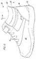
- FIG. 10is a medial side elevation of footwear of a third embodiment of the present invention.
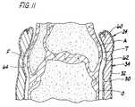
- FIG. 11is cross section of the footwear of the third embodiment taken in the plane of line 11 — 11 of FIG. 10 ;
- FIG. 12is cross section of the footwear of the third embodiment taken in the plane of line 12 — 12 of FIG. 10 ;
- FIG. 13is a medial elevation of one embodiment of footwear of this invention incorporating a medial ankle pad to reduce ankle swelling;
- FIG. 14is a lateral elevation of the footwear of FIG. 13 incorporating a lateral ankle pad to further reduce ankle swelling;
- FIG. 15is a horizontal cross-sectional view on line 15 — 15 of FIG. 13 .
- footwear of a first embodiment of the present inventionis designated in its entirety by the reference numeral 20 .
- the footwear 20includes a sole, generally designated by 22 , for supporting a foot (not shown) and an upper, generally designated by 24 , attached to the sole for covering the foot.
- the sole 22 and upper 24define an interior 26 of the footwear.
- the interior 26is sized and shaped for receiving the foot.
- the upper 24includes a lining 30 forming an inner surface of the upper adapted for engaging the foot O when it is received in the interior 26 of the footwear 20 .
- the lining 30may be made of other materials without departing from the scope of the present invention, in the first embodiment the lining is made of cloth.
- the upper 24also includes an outer shell 32 forming an outer surface of the upper and an exterior of the footwear 20 .
- the shell 32may be made of other materials without departing from the scope of the present invention, in the first embodiment the shell is made of leather.
- a compressible cushioningis sandwiched between the lining 30 and the outer shell 32 for permitting the upper 24 to conform to the foot O when it is received in the interior 26 of the footwear 20 to improve the fit of the footwear.
- the cushioning 34may be made of other materials without departing from the scope of the present invention, in the first embodiment the cushioning is made of an open cell foam.
- the cushioning 34may be made of other conventional footwear materials such as gels, closed cell foams and synthetic rubbers.
- the lining 30 , shell 32 and cushioning 34may be assembled using any conventional means such as with adhesives or by sewing.
- the compressible cushioning 34is sized, shaped and positioned in the upper to at least partially surround one or more protrusions extending from the foot O.
- the cushioning 34at least partially surrounds the first and fifth metatarsal heads H 1 , H 5 , respectively, and a portion of a fifth toe T 5 corresponding to a portion of a fifth proximal phalanx P 5 .
- the cushioning 34is at least partially omitted from areas on the upper 24 corresponding to these protrusions thereby forming recesses 40 , 42 for accommodating the various protrusions to relieve pressure applied to the foot O by the upper at the protrusions.
- the nominal sizes of the recesses 40 , 42will vary depending upon the size of the foot O. Measurements may be taken to determine the sizes of the recesses 40 , 42 .
- the recess 40 for accommodating the first metatarsal head H 1 in footwear 20 sized for a typical adult female (e.g, size 9)is generally oval having a length of about 11 ⁇ 4 to about 11 ⁇ 2 inches and a height of about one inch. Further, the recess 40 has a nominal depth of about 1 ⁇ 8 inch.
- the recess 42 for accommodating the first metatarsal head H 1 and the portion of the fifth toe T 5 corresponding to the fifth proximal phalanx P 5 in footwear 20 sized for a typical adult male (e.g., size 10)is an highly elongate oval having a length of about 11 ⁇ 2 to 2 inches and a height of about 1 ⁇ 2 to about 3 ⁇ 4 inches. Further, the recess 42 has a nominal depth of about 1 ⁇ 8 inches. As illustrated in FIGS. 6 and 7 , the recesses 40 , 42 of the first preferred embodiment have generally rounded shapes and profiles. In addition, the recess 42 may be formed as two separate recesses—one recess for accommodating the head of the fifth metatarsal H 5 and one recess for accommodating the fifth proximal phalanx P 5 .
- the cushioning 34does not have recesses. Rather, the cushioning 34 is made of a softer (i.e., more compressible) material in the areas of the upper 24 which correspond to the protrusions so the cushioning compresses to accommodate the protrusions.
- the cushioning 34is formed from a first material 50 having a first compressibility selected for cushioning corresponding areas of the foot O, and a second material 52 having a second compressibility greater than the first compressibility selected for accommodating corresponding areas of the foot O.
- the first material 50is sized, shaped and positioned on the upper 24 for at least partially surrounding the protrusion extending from the foot.
- the second material 52is sized, shaped and positioned on an area of the upper 24 corresponding to the location of the protrusion so that the upper applies less pressure to the protrusion than to portions of the foot O surrounding the protrusion.
- the parts of the upper 24 having the second material 52are similarly sized, shaped and positioned to the recesses 40 , 42 in the footwear of the first embodiment.
- the first and second materials 50 , 52may have different chemistries from each other or they may have similar chemistries. Where the materials 50 , 52 have the same chemistries, they may be integrally formed and the second material may be perforated or otherwise weakened to provide increased compressibility.
- Other features of the footwear 20 of the second embodimentare similar to those of the footwear of the first embodiment and will not be described in further detail.
- footwear 20 of a third embodimenthas a collar 60 which extends above the distal heads of the tibia T and fibula F.
- the upper 24 of the footwear 20 of the third embodimenthas a lining 30 , an outer shell 32 and a compressible cushioning 34 is sandwiched between the lining and the outer shell.
- the cushioning 34 of the footwear 20 of the third embodimentis sized, shaped and positioned in the upper 24 to at least partially surround a medial portion and a lateral portion of an ankle A corresponding to a distal head of a tibia T and a distal head of a fibula F when the foot O is in the interior 26 of the footwear 20 .
- the cushioning 34is omitted from an area of the upper 24 corresponding to the distal heads of the tibia T and fibular F thereby forming recesses 62 , 64 in the upper for accommodating the portions of the ankle A to relieve pressure applied to the ankle by the upper.
- the nominal sizes of the recesses 62 , 64will vary depending upon the size of the foot O.
- the recess 62 for accommodating the distal head of the tibia T in footwear 20 sized for a typical adult maleis generally oval having a length of about 11 ⁇ 2 to about 13 ⁇ 4 inches and a height of about 11 ⁇ 4 to about 11 ⁇ 2 inches.
- the recess 64 for accommodating the distal head of the fibula F in footwear 20 sized for a typical adult maleis generally oval having a length of about 1 to about 11 ⁇ 4 inches and a height of about 11 ⁇ 4 to about 11 ⁇ 2 inches.
- the recesses 62 , 64has a nominal depth of about 1 ⁇ 8 to about 3/16 inch.
- the fibular recess 64is preferably below and behind the tibial recess 62 . Most preferably, the fibular recess 64 is offset from the tibial recess 62 by a distance of about 1 ⁇ 2 to about 3 ⁇ 4 inches measured in a horizontal plane as shown in FIG. 12 , and by a distance of about 1 ⁇ 2 to about 3 ⁇ 4 inches in a vertical plane as shown in FIG. 11 . Further, it is envisioned that the upper portions of the cushioning 34 and the recesses 62 , 64 may be omitted in footwear 20 having a low collar 60 . It is also envisioned that the recesses 62 , 64 may have open bottoms forming openings through the upper 24 for accommodating the corresponding portion of the ankle without departing from the scope of the present invention.
- the cushioning 34 surrounding the various portions of the foot Ois illustrated as being unitary, those skilled in the art will appreciate that the cushioning may be formed from more than one piece and/or in more than one layer without departing from the scope of the present invention. Further, the cushioning 34 of the third embodiment may be made from two materials similarly to the cushioning of the second embodiment without departing from the scope of the present invention. Still further as will be appreciated by those skilled in the art, the areas of the upper 24 corresponding to the protrusions preferably do not contain seams to avoid abrasiveness, inelasticity and stiffness in these areas.
- FIGS. 13–15show footwear, generally designated 101 , incorporating one or more ankle pads of this invention.
- the footwear 101comprises an upper 105 having an outer shell 107 of conventional material (e.g., leather, cloth), an inner lining 109 of conventional material (e.g., cotton fabric, synthetic material, Gortex®), and a filler material 111 (e.g., conventional cotton or foam filler material) between the shell and lining.
- a medial ankle pad 113is also sandwiched between the lining and the shell.
- the pad 113( FIG. 13 ) has a bottom section 113 A and a pair of spaced-apart side sections 113 B extending up from the bottom section.
- the pad 113is U-shaped with a curved bottom section 113 A and substantially straight side sections 113 B, but other configurations are possible.
- the pad 113is of a firm but resiliently compressible material and is sized and positioned within the upper 105 of the footwear such that when the foot and ankle are received in the footwear, the bottom section 113 A of the pad is disposed immediately below the medial malleolus 119 of the tibia 121 of the leg, and the side sections 113 B of the pad extend up along opposite sides of the medial malleolus to a level generally at or above the distal neck 123 of the tibia, i.e., the location where the shaft of the tibia meets the medial malleolus.
- FIG. 1The particular embodiment shown in FIG.
- the bottom section 113 Aadvantageously has a curved bottom section 113 A to conform to the lower end of the medial malleolus 119 , but it will be understood that the bottom section can have other shapes so long as the bone structure of the tibia below the distal neck 123 , including the medial malleolus 119 , is received within the U-recess of the ankle pad 113 and the pad is positioned for applying pressure to the surrounding tissue all the way up to about at least the distal neck 123 of the tibia, as will be described.
- the ankle pad 113is of a resiliently compressible material such as Poron® cellular urethane foam having a firmness which is sufficient to apply an intermittent compressive force to the tissue surrounding the medial malleolus 119 and distal neck 123 of the tibia 121 during motion of the foot, as during walking and running.
- the ankle padhas a Shore C durometer in the range of 25–70, the magnitude of which may vary depending on the particular type of shoe.
- the durometer of the pad 113may be in the range of 25–36 Shore C; for an athletic shoe the durometer may be in the range of 37–55 Shore C; and for a heavy boot (e.g., military or construction) the durometer may be in the range of 60–70 Shore C.
- the filler material 111 A on the inside of the U-padi.e., the filler material between the side sections 113 B of the U-pad (see FIG. 15 ) should be softer and have a resistance to compression less than that of the U-pad 113 itself.
- the inside filler material 111 Ahas a durometer at least 10 units less than the durometer of the pad 113 (e.g., 10–15 durometer units less on the Shore C scale).
- the filler material 111 B on the outside of the pad 113may have a hardness the same as, or less than, or greater than the hardness of the pad 113 .
- the inside and outside filler materials 111 A, 111 Bmay have the same composition or be of different compositions.
- the inside filler material 111 Amay have a thickness less than that of the U-pad 113 . Alternatively, the inside filler material 111 A may be omitted entirely.
- the outside filler material 111 Bmay have a thickness the same as or less than the thickness of the U-pad 113 .
- the filler material between the outer shell 107 and inner lining 109 in the heel area of the footwearmay be constructed as a conventional heel counter.
- the footwear 101is preferably secured relatively tightly on the foot so that the U-pad 113 is pressed snugly against the tissue below and on opposite sides of the medial malleolus 119 and on opposite sides of the distal neck 123 of the tibia 121 .
- the pad 113intermittently applies pressure against the medial side of the ankle A and tissue T surrounding the medial malleolus 119 and distal neck 123 of the tibia to simulate a pumping or milking action.
- the footwear 101also includes a second (lateral) pad 131 sandwiched between the lining 109 and the outer shell 107 at the lateral side of the ankle to further increase the removal of interstitial fluid from the ankle area.
- the lateral pad 131is preferably similar to the first (medial) pad 113 , being generally U-shaped and having a bottom section 131 A and a pair of spaced-apart side sections 131 B extending up from the bottom section (see FIG. 14 ).
- This pad 131is also of a firm but resiliently compressible material having a hardness and resistance to compression greater than that of the inside filler material 111 A, as discussed above regarding the medial U-pad 113 .
- the lateral pad 131may be constructed of the same material as the medial pad 113 and have the same durometer hardness and resistance to compression as that noted above.
- the U-pad 131is sized and positioned within the footwear 101 such that when the foot O and ankle A are received in the footwear and the footwear is secured on the foot relatively tightly, the bottom section 131 A of the pad is disposed immediately below the lateral malleolus 133 of the fibula 135 of the foot and the side sections 131 B of the pad extend up along opposite sides of the lateral malleolus to a level generally at or above the distal neck 137 of the fibula.
- the bottom section 131 Acan have other shapes.
- the bone structure of the fibula below the distal neck 137 , including the lateral malleolus 133is received within the U-recess of the ankle pad 131 and the pad is positioned for applying pressure to the surrounding tissue all the way up to at least the distal neck 137 of the fibula.
- the lateral pad 131functions in the same manner as the medial pad 113 (i.e., creates a pumping action against the tissue surrounding the lateral malleous and distal neck of the fibula during foot movement) to reduce swelling of the ankle.
- footwear 101 described abovehas both medial and lateral pads 113 , 131 , it will be understood that footwear of this invention could include only one of these pads at either side of the foot.
- the size of the U-pads 113 and 131will vary depending on the size of the footwear and person wearing it. In general, however, the size should be such that the U-shape of each pad relatively closely conforms to the distal neck of the respective tibia and fibula and associated medial and lateral malleolus.
- the spacing between the side sections 113 B of the medial U-pad 113generally corresponds to the width of the lower end of the medial malleolus 119
- the spacing between the side sections 131 B of the lateral U-pad 131generally corresponds to the width of the lower end of the lateral malleolus 137 .
- each pad 113 , 131is typically located forward and above the lateral pad 131 .
- the side sections of each pad 113 , 131should extend up to at least about the distal neck of the respective tibia and fibula, as noted above.
- pads 113 , 131 described abovewill be made as an integral part of the footwear 101 during the manufacturing process. However, it is contemplated that pad(s) could be sold separate from the footwear and retrofitted in the footwear at a later date.
Landscapes
- Health & Medical Sciences (AREA)
- Epidemiology (AREA)
- General Health & Medical Sciences (AREA)
- Public Health (AREA)
- Footwear And Its Accessory, Manufacturing Method And Apparatuses (AREA)
Abstract
Description
Claims (12)
Priority Applications (2)
| Application Number | Priority Date | Filing Date | Title |
|---|---|---|---|
| US10/730,354US7028419B2 (en) | 2000-08-04 | 2003-12-08 | Footwear |
| PCT/US2004/040893WO2005055753A1 (en) | 2003-12-08 | 2004-12-07 | Footwear |
Applications Claiming Priority (3)
| Application Number | Priority Date | Filing Date | Title |
|---|---|---|---|
| US22343700P | 2000-08-04 | 2000-08-04 | |
| US09/921,957US6671981B2 (en) | 2000-08-04 | 2001-08-03 | Footwear |
| US10/730,354US7028419B2 (en) | 2000-08-04 | 2003-12-08 | Footwear |
Related Parent Applications (1)
| Application Number | Title | Priority Date | Filing Date |
|---|---|---|---|
| US09/921,957Continuation-In-PartUS6671981B2 (en) | 2000-08-04 | 2001-08-03 | Footwear |
Publications (2)
| Publication Number | Publication Date |
|---|---|
| US20040111923A1 US20040111923A1 (en) | 2004-06-17 |
| US7028419B2true US7028419B2 (en) | 2006-04-18 |
Family
ID=34677157
Family Applications (1)
| Application Number | Title | Priority Date | Filing Date |
|---|---|---|---|
| US10/730,354Expired - Fee RelatedUS7028419B2 (en) | 2000-08-04 | 2003-12-08 | Footwear |
Country Status (2)
| Country | Link |
|---|---|
| US (1) | US7028419B2 (en) |
| WO (1) | WO2005055753A1 (en) |
Cited By (10)
| Publication number | Priority date | Publication date | Assignee | Title |
|---|---|---|---|---|
| US20090083998A1 (en)* | 2007-09-27 | 2009-04-02 | Nike, Inc. | Article of Footwear for Water Sports |
| US20100299961A1 (en)* | 2009-05-28 | 2010-12-02 | Nike, Inc. | Article of Footwear With A Shape Correcting Member |
| US8529267B2 (en) | 2010-11-01 | 2013-09-10 | Nike, Inc. | Integrated training system for articles of footwear |
| US8573981B2 (en) | 2009-05-29 | 2013-11-05 | Nike, Inc. | Training system for an article of footwear with a ball control portion |
| US8616892B2 (en) | 2009-04-02 | 2013-12-31 | Nike, Inc. | Training system for an article of footwear with a traction system |
| US8632342B2 (en) | 2009-05-28 | 2014-01-21 | Nike, Inc. | Training system for an article of footwear |
| US8697970B2 (en) | 2009-01-12 | 2014-04-15 | Gavin Harrison | Cymbal mounting assembly |
| US20140283410A1 (en)* | 2013-03-22 | 2014-09-25 | Reebok International Limited | Molded Footwear Upper And Method Of Making Same |
| US20170238658A1 (en)* | 2016-02-24 | 2017-08-24 | Under Armour, Inc. | Footwear Upper With Zonal Support Areas |
| US20230117040A1 (en)* | 2021-10-14 | 2023-04-20 | Adidas Ag | Anatomical padding for a shoe |
Families Citing this family (8)
| Publication number | Priority date | Publication date | Assignee | Title |
|---|---|---|---|---|
| US7681333B2 (en)* | 2004-10-29 | 2010-03-23 | The Timberland Company | Shoe footbed system with interchangeable cartridges |
| US7461470B2 (en)* | 2004-10-29 | 2008-12-09 | The Timberland Company | Shoe footbed system and method with interchangeable cartridges |
| US7762008B1 (en)* | 2005-09-07 | 2010-07-27 | The Timberland Company | Extreme service footwear |
| US9573331B2 (en)* | 2010-12-10 | 2017-02-21 | Converse Inc. | Thermoplastic polyurethane infused mesh |
| US9907363B2 (en)* | 2015-04-21 | 2018-03-06 | Nike, Inc. | Strap securing systems for articles of footwear and other foot-receiving devices |
| AT517606B1 (en)* | 2015-12-22 | 2017-03-15 | Fischer Sports Gmbh | liner |
| US11369163B1 (en)* | 2019-12-03 | 2022-06-28 | Jesse Offutt | Athletic shoe having integral ankle support |
| JP7741633B2 (en)* | 2020-12-23 | 2025-09-18 | 株式会社アシックス | Shoes |
Citations (59)
| Publication number | Priority date | Publication date | Assignee | Title |
|---|---|---|---|---|
| US1020160A (en) | 1911-09-30 | 1912-03-12 | Lewis S Rowe | Shoe-pad. |
| US1055768A (en) | 1912-10-07 | 1913-03-11 | Samuel H Levee | Shoe attachment. |
| US1137092A (en) | 1913-10-31 | 1915-04-27 | Columbus A Sharp | Insole. |
| GB217833A (en) | 1923-10-30 | 1924-06-26 | Isaac Fleming | Improvements in and relating to insoles for boots and shoes |
| US1958619A (en) | 1933-02-17 | 1934-05-15 | Harris L Handler | Nonslip cushion pad for shoe counters |
| US2061540A (en) | 1933-12-11 | 1936-11-17 | Thompson Bros Shoe Co | Shoe |
| US2075552A (en) | 1936-11-02 | 1937-03-30 | Clarence H Stemmons | Sock liner foot corrector |
| US2119807A (en) | 1936-01-07 | 1938-06-07 | Myron M Farley | Heel and arch cushion and support |
| US2261041A (en) | 1939-10-02 | 1941-10-28 | Ross A Tennant | Orthopedic device |
| US2312911A (en) | 1941-02-26 | 1943-03-02 | Jewtraw Charles | Skating shoe and the like |
| US2332473A (en) | 1940-12-27 | 1943-10-19 | Abraham B Salander | Foot corrective device |
| US2821032A (en) | 1954-12-24 | 1958-01-28 | Walk Rite Appliances Proprieta | Orthopedic appliance for flat-footedness |
| US2828555A (en) | 1952-12-24 | 1958-04-01 | Ledos Maurice Emile Auguste | Footwear |
| US2918059A (en) | 1957-12-11 | 1959-12-22 | Scholl Mfg Co Inc | Foot corrective pad |
| US2918734A (en) | 1958-11-24 | 1959-12-29 | A R Hyde & Sons Company | Ankle bone protector |
| FR1222370A (en) | 1959-04-28 | 1960-06-09 | Fitment insole for all shoes | |
| US3068872A (en) | 1959-08-11 | 1962-12-18 | Brody Alec Elliot | Foot supporting device |
| US3309797A (en) | 1964-03-17 | 1967-03-21 | Poitras Joseph Arthur | Anti-inversion device for sneakers |
| US3333353A (en) | 1963-07-19 | 1967-08-01 | Garcia Pedro Arnau | Manufacture of footwear |
| US3419974A (en) | 1966-03-14 | 1969-01-07 | Robert B. Lange | Ski boot |
| FR2015914A1 (en) | 1968-08-19 | 1970-04-30 | Usm Corp | |
| US3726287A (en) | 1970-07-16 | 1973-04-10 | S Wikler | Shoe construction with foot-stabilizing appliance |
| US3750310A (en) | 1971-04-01 | 1973-08-07 | S Messner | Boot,especially ski boot |
| US4272899A (en) | 1979-10-15 | 1981-06-16 | Brooks Jeffrey S | Footwear |
| US4435910A (en) | 1982-03-12 | 1984-03-13 | Michel Marc | Shoe insole |
| US4495942A (en)* | 1981-12-04 | 1985-01-29 | Palumbo Pasquale M | Dynamic ankle brace |
| US4503576A (en) | 1981-08-19 | 1985-03-12 | Brown Dennis N | Orthotic appliance and method of making |
| US4537556A (en)* | 1983-05-12 | 1985-08-27 | Tharp Emery C | Reciprocating backhoe bucket |
| US4590932A (en)* | 1984-05-14 | 1986-05-27 | Wilkerson Gary B | Ankle-sprain edema-control boot assembly |
| US4627178A (en) | 1983-02-28 | 1986-12-09 | Sullivan James B | Molded shoe innersole |
| US4633877A (en) | 1984-08-07 | 1987-01-06 | Duramet Systems, Inc. | Dynamic foot support and kit therefor |
| US4702255A (en) | 1985-06-17 | 1987-10-27 | Schenkl Joseph L | Orthopedic apparatus |
| US4704808A (en) | 1986-09-25 | 1987-11-10 | Highland Import Corporation | Shoe having a rigid back part and flexible forepart |
| US4719926A (en) | 1986-02-28 | 1988-01-19 | Nelson Ronald E | Hinged foot and ankle brace |
| US4726126A (en) | 1985-06-10 | 1988-02-23 | Puma Ag Rudolf Dassler Sport | Shoe, particularly intended for rehabilitation purposes |
| US4739765A (en) | 1985-06-28 | 1988-04-26 | Bio Balance Orthotics Inc. | Arch support |
| US4864739A (en) | 1986-03-14 | 1989-09-12 | Salomon S.A. | Internal boot sole |
| US4869001A (en) | 1986-03-07 | 1989-09-26 | Superfeet In-Shoe Systems, Inc. | Foot and ankle orthotic for a skate boot or the like, and method |
| US4876806A (en) | 1986-01-29 | 1989-10-31 | Nike, Inc. | Asymmetric shoe |
| US4879821A (en) | 1987-09-04 | 1989-11-14 | Hyde Athletic Industries Inc. | Insole construction |
| US4882856A (en) | 1988-04-25 | 1989-11-28 | Glancy John J | Cushion wedge for custom control of impact and pronation upon heel-strike in various weights of wearers |
| EP0350517A1 (en) | 1988-07-12 | 1990-01-17 | KLEYLEIN, Horst | Orthopedic insert for shoes, particularly for sports shoes |
| US4901390A (en) | 1988-09-26 | 1990-02-20 | Dynamic Foam Products, Inc. | Method of manufacturing custom insoles for athletic shoes |
| US4977691A (en) | 1988-08-23 | 1990-12-18 | Spenco Medical Corporation | Shoe insole with bottom surface compression relief |
| US5000195A (en)* | 1988-06-21 | 1991-03-19 | Deroyal Industries, Inc. | Ankle splint |
| US5067257A (en) | 1990-10-18 | 1991-11-26 | Sven Coomer | Injection fitted boot liner |
| US5092347A (en) | 1990-03-19 | 1992-03-03 | Shaffer David E | Personalized sock kit for relieving foot and ankle pain |
| US5146698A (en) | 1989-05-08 | 1992-09-15 | Tilles Harvey G | Shoe insole proform II |
| US5185000A (en)* | 1991-02-18 | 1993-02-09 | Beiersdorf Ag | Ankle joint bandage |
| US5384973A (en) | 1992-12-11 | 1995-01-31 | Nike, Inc. | Sole with articulated forefoot |
| US5408761A (en) | 1992-04-09 | 1995-04-25 | A. D. One Sports, Inc. | Sport shoe and support system |
| US5823195A (en)* | 1995-05-09 | 1998-10-20 | Shook; C. David | Ankle pad |
| US5924218A (en) | 1994-11-10 | 1999-07-20 | Salomon S. A. | Internal liner for a boot |
| US6012726A (en) | 1997-02-13 | 2000-01-11 | K-2 Corporation | In-line skate with temperature dependent support |
| US6023857A (en) | 1998-09-21 | 2000-02-15 | Converse Inc. | Shoe with removable midsole |
| US6041524A (en) | 1998-10-05 | 2000-03-28 | Jeffrey S. Brooks, Inc. | Footwear having recessed heel cup |
| US20020020081A1 (en) | 2000-08-04 | 2002-02-21 | Brooks Jeffrey S. | Footwear |
| US6442875B1 (en)* | 1997-09-18 | 2002-09-03 | Michel Joubert | Footwear |
| US20030154627A1 (en) | 2002-02-19 | 2003-08-21 | Shimano Inc. | Boot liner |
- 2003
- 2003-12-08USUS10/730,354patent/US7028419B2/ennot_activeExpired - Fee Related
- 2004
- 2004-12-07WOPCT/US2004/040893patent/WO2005055753A1/enactiveApplication Filing
Patent Citations (61)
| Publication number | Priority date | Publication date | Assignee | Title |
|---|---|---|---|---|
| US1020160A (en) | 1911-09-30 | 1912-03-12 | Lewis S Rowe | Shoe-pad. |
| US1055768A (en) | 1912-10-07 | 1913-03-11 | Samuel H Levee | Shoe attachment. |
| US1137092A (en) | 1913-10-31 | 1915-04-27 | Columbus A Sharp | Insole. |
| GB217833A (en) | 1923-10-30 | 1924-06-26 | Isaac Fleming | Improvements in and relating to insoles for boots and shoes |
| US1958619A (en) | 1933-02-17 | 1934-05-15 | Harris L Handler | Nonslip cushion pad for shoe counters |
| US2061540A (en) | 1933-12-11 | 1936-11-17 | Thompson Bros Shoe Co | Shoe |
| US2119807A (en) | 1936-01-07 | 1938-06-07 | Myron M Farley | Heel and arch cushion and support |
| US2075552A (en) | 1936-11-02 | 1937-03-30 | Clarence H Stemmons | Sock liner foot corrector |
| US2261041A (en) | 1939-10-02 | 1941-10-28 | Ross A Tennant | Orthopedic device |
| US2332473A (en) | 1940-12-27 | 1943-10-19 | Abraham B Salander | Foot corrective device |
| US2312911A (en) | 1941-02-26 | 1943-03-02 | Jewtraw Charles | Skating shoe and the like |
| US2828555A (en) | 1952-12-24 | 1958-04-01 | Ledos Maurice Emile Auguste | Footwear |
| US2821032A (en) | 1954-12-24 | 1958-01-28 | Walk Rite Appliances Proprieta | Orthopedic appliance for flat-footedness |
| US2918059A (en) | 1957-12-11 | 1959-12-22 | Scholl Mfg Co Inc | Foot corrective pad |
| US2918734A (en) | 1958-11-24 | 1959-12-29 | A R Hyde & Sons Company | Ankle bone protector |
| FR1222370A (en) | 1959-04-28 | 1960-06-09 | Fitment insole for all shoes | |
| US3068872A (en) | 1959-08-11 | 1962-12-18 | Brody Alec Elliot | Foot supporting device |
| US3333353A (en) | 1963-07-19 | 1967-08-01 | Garcia Pedro Arnau | Manufacture of footwear |
| US3309797A (en) | 1964-03-17 | 1967-03-21 | Poitras Joseph Arthur | Anti-inversion device for sneakers |
| US3419974A (en) | 1966-03-14 | 1969-01-07 | Robert B. Lange | Ski boot |
| FR2015914A1 (en) | 1968-08-19 | 1970-04-30 | Usm Corp | |
| US3726287A (en) | 1970-07-16 | 1973-04-10 | S Wikler | Shoe construction with foot-stabilizing appliance |
| US3750310A (en) | 1971-04-01 | 1973-08-07 | S Messner | Boot,especially ski boot |
| US4272899A (en) | 1979-10-15 | 1981-06-16 | Brooks Jeffrey S | Footwear |
| US4503576A (en) | 1981-08-19 | 1985-03-12 | Brown Dennis N | Orthotic appliance and method of making |
| US4495942A (en)* | 1981-12-04 | 1985-01-29 | Palumbo Pasquale M | Dynamic ankle brace |
| US4435910A (en) | 1982-03-12 | 1984-03-13 | Michel Marc | Shoe insole |
| US4627178A (en) | 1983-02-28 | 1986-12-09 | Sullivan James B | Molded shoe innersole |
| US4537556A (en)* | 1983-05-12 | 1985-08-27 | Tharp Emery C | Reciprocating backhoe bucket |
| US4590932A (en)* | 1984-05-14 | 1986-05-27 | Wilkerson Gary B | Ankle-sprain edema-control boot assembly |
| US4633877A (en) | 1984-08-07 | 1987-01-06 | Duramet Systems, Inc. | Dynamic foot support and kit therefor |
| US4726126A (en) | 1985-06-10 | 1988-02-23 | Puma Ag Rudolf Dassler Sport | Shoe, particularly intended for rehabilitation purposes |
| US4702255A (en) | 1985-06-17 | 1987-10-27 | Schenkl Joseph L | Orthopedic apparatus |
| US4739765A (en) | 1985-06-28 | 1988-04-26 | Bio Balance Orthotics Inc. | Arch support |
| US4876806A (en) | 1986-01-29 | 1989-10-31 | Nike, Inc. | Asymmetric shoe |
| US4719926A (en) | 1986-02-28 | 1988-01-19 | Nelson Ronald E | Hinged foot and ankle brace |
| US4869001A (en) | 1986-03-07 | 1989-09-26 | Superfeet In-Shoe Systems, Inc. | Foot and ankle orthotic for a skate boot or the like, and method |
| US4864739A (en) | 1986-03-14 | 1989-09-12 | Salomon S.A. | Internal boot sole |
| US4704808A (en) | 1986-09-25 | 1987-11-10 | Highland Import Corporation | Shoe having a rigid back part and flexible forepart |
| US4879821A (en) | 1987-09-04 | 1989-11-14 | Hyde Athletic Industries Inc. | Insole construction |
| US4882856A (en) | 1988-04-25 | 1989-11-28 | Glancy John J | Cushion wedge for custom control of impact and pronation upon heel-strike in various weights of wearers |
| US5000195A (en)* | 1988-06-21 | 1991-03-19 | Deroyal Industries, Inc. | Ankle splint |
| EP0350517A1 (en) | 1988-07-12 | 1990-01-17 | KLEYLEIN, Horst | Orthopedic insert for shoes, particularly for sports shoes |
| EP0350517B1 (en) | 1988-07-12 | 1992-07-22 | KLEYLEIN, Horst | Orthopedic insert for shoes, particularly for sports shoes |
| US4977691A (en) | 1988-08-23 | 1990-12-18 | Spenco Medical Corporation | Shoe insole with bottom surface compression relief |
| US4901390A (en) | 1988-09-26 | 1990-02-20 | Dynamic Foam Products, Inc. | Method of manufacturing custom insoles for athletic shoes |
| US5146698A (en) | 1989-05-08 | 1992-09-15 | Tilles Harvey G | Shoe insole proform II |
| US5092347A (en) | 1990-03-19 | 1992-03-03 | Shaffer David E | Personalized sock kit for relieving foot and ankle pain |
| US5067257A (en) | 1990-10-18 | 1991-11-26 | Sven Coomer | Injection fitted boot liner |
| US5185000A (en)* | 1991-02-18 | 1993-02-09 | Beiersdorf Ag | Ankle joint bandage |
| US5408761A (en) | 1992-04-09 | 1995-04-25 | A. D. One Sports, Inc. | Sport shoe and support system |
| US5384973A (en) | 1992-12-11 | 1995-01-31 | Nike, Inc. | Sole with articulated forefoot |
| US5924218A (en) | 1994-11-10 | 1999-07-20 | Salomon S. A. | Internal liner for a boot |
| US5823195A (en)* | 1995-05-09 | 1998-10-20 | Shook; C. David | Ankle pad |
| US6012726A (en) | 1997-02-13 | 2000-01-11 | K-2 Corporation | In-line skate with temperature dependent support |
| US6442875B1 (en)* | 1997-09-18 | 2002-09-03 | Michel Joubert | Footwear |
| US20030093923A1 (en) | 1997-09-18 | 2003-05-22 | Michel Joubert | Footwear |
| US6023857A (en) | 1998-09-21 | 2000-02-15 | Converse Inc. | Shoe with removable midsole |
| US6041524A (en) | 1998-10-05 | 2000-03-28 | Jeffrey S. Brooks, Inc. | Footwear having recessed heel cup |
| US20020020081A1 (en) | 2000-08-04 | 2002-02-21 | Brooks Jeffrey S. | Footwear |
| US20030154627A1 (en) | 2002-02-19 | 2003-08-21 | Shimano Inc. | Boot liner |
Non-Patent Citations (24)
| Title |
|---|
| ALIMED, Your Best Single Source. . . , "Podiatry Today", Jul./Aug. 1997, p. 43. |
| Allied OSI Labs, Allied OSI Footlights are Light in Price, "Podiatry Today", Jul./Aug. 1997, p. 84. |
| Bauerfiend, Viscoheel, the viscoelastic heel cushions . . . , "Biomechanics", Jan. 1997, p. 57. |
| Bio-Orthopaedic Laboratory, Standard Foot Orthotics, "Biomechanics", Sep. 1995, p. 76. |
| Bird & Cronin, Inc., A Complete Line of Pre-Molded Silicone Foot Orthotics, "Biomechanics", Jun. 1997, p. 44. |
| Bloch Orthotic Labs, Shelling Out Too Much for Orthotics?, "Podiatric Products", Sep. 1994. p. 10. |
| Bolt Systems, Inc., Quality Prefabricated Orthopaedic Appliances, "Biomechanics", Jun. 1997, p. 74. |
| Brooks, Visser and Duddy, "Mid-West Podiatry and Associates, Inc.", brochure, 8 pages. |
| CJ Foot Orthotics, All This for Less, "Podiatry Management", Jun. 1996, p. 101. |
| COMED, The Power of 78, "Podiatry Today", Oct. 1993, p. 39. |
| DARCO, The One Stop Footcare Shop, "Biomechanics", Sep. 1995, p. 18. |
| Dr. Scholl's, Now Your Patients Are One Step Closer to Pain Relief, "Podiatry Today", Jul./Aug. 1997, p. 33. |
| IEM Medical Technologies, Sorbothane II Heel Cups, "Biomechanics", Sep. 1995, p. 66. |
| International Search Report, Dated Apr. 21, 2005, 3 Pages. |
| IPOS Orthopedics Industry, Soft-Base Soft-Ipocon, "Podiatric Products", Sep. 1994, p. 37. |
| Johnson & Johnson,Biomechanics, "Biomechanics", Sep. 1995, p. 1. |
| M-F Athletic Company, If Achilles Was Alive, He'd Want a Pair of M-F Heel Protectors!, "Podiatric Products", Sep. 1994, p. 55. |
| Ortho-Dynactive, Inc., Tread Lightly, "Biomechanics", Jan. 1997, p. 71. |
| Performance Materials Corporation, Into the Deep Blue, "Podiatry Today", Jul./Aug. 1997, p. 44. |
| Rieken's Orthotics Laboratory, Our Dealers Become Old Friends. . . , "Biomechanics", Sep. 1995, p. 16. |
| SILIPOS, MOVE, "Biomechanics", Jun. 1997, p. 87. |
| STJ Orthotic Services Inc., Your Heel Pain Patients Will be Floating on Water, "Podiatry Management", Jun. 1996, p. 1. |
| The Elford Group LTD., Nothing Fits Like SOCS, "Podiatry Management", Jun. 1996, p. 47. |
| The Foot Store, The Best Kind of Support. . . , "Biomechanics", Sep. 1995, p. 76. |
Cited By (16)
| Publication number | Priority date | Publication date | Assignee | Title |
|---|---|---|---|---|
| US8230617B2 (en) | 2007-09-27 | 2012-07-31 | Nike, Inc. | Article of footwear for water sports |
| US20090083998A1 (en)* | 2007-09-27 | 2009-04-02 | Nike, Inc. | Article of Footwear for Water Sports |
| US8697970B2 (en) | 2009-01-12 | 2014-04-15 | Gavin Harrison | Cymbal mounting assembly |
| US8616892B2 (en) | 2009-04-02 | 2013-12-31 | Nike, Inc. | Training system for an article of footwear with a traction system |
| US20100299961A1 (en)* | 2009-05-28 | 2010-12-02 | Nike, Inc. | Article of Footwear With A Shape Correcting Member |
| US8196321B2 (en)* | 2009-05-28 | 2012-06-12 | Nike, Inc. | Article of footwear with a shape correcting member |
| US8632342B2 (en) | 2009-05-28 | 2014-01-21 | Nike, Inc. | Training system for an article of footwear |
| US8573981B2 (en) | 2009-05-29 | 2013-11-05 | Nike, Inc. | Training system for an article of footwear with a ball control portion |
| US8529267B2 (en) | 2010-11-01 | 2013-09-10 | Nike, Inc. | Integrated training system for articles of footwear |
| US9623309B2 (en) | 2010-11-01 | 2017-04-18 | Nike, Inc. | Integrated training system for articles of footwear |
| US20140283410A1 (en)* | 2013-03-22 | 2014-09-25 | Reebok International Limited | Molded Footwear Upper And Method Of Making Same |
| US10499706B2 (en)* | 2013-03-22 | 2019-12-10 | Reebok International Limited | Molded footwear upper and method of making same |
| US12042011B2 (en) | 2013-03-22 | 2024-07-23 | Reebok International Limited | Molded footwear upper and method of making same |
| US20170238658A1 (en)* | 2016-02-24 | 2017-08-24 | Under Armour, Inc. | Footwear Upper With Zonal Support Areas |
| US20230117040A1 (en)* | 2021-10-14 | 2023-04-20 | Adidas Ag | Anatomical padding for a shoe |
| US12225978B2 (en)* | 2021-10-14 | 2025-02-18 | Adidas Ag | Anatomical padding for a shoe |
Also Published As
| Publication number | Publication date |
|---|---|
| WO2005055753A1 (en) | 2005-06-23 |
| US20040111923A1 (en) | 2004-06-17 |
Similar Documents
| Publication | Publication Date | Title |
|---|---|---|
| US7028419B2 (en) | Footwear | |
| JP3942027B2 (en) | Footwear sole | |
| US6725578B2 (en) | Joint protective shoe construction | |
| US20010000369A1 (en) | Insole | |
| JP2009514599A (en) | Insoles | |
| KR20120129909A (en) | Footwear with toe aligner structure | |
| US6671981B2 (en) | Footwear | |
| WO2004100693A1 (en) | Cantilevered shoe construction | |
| TW201715979A (en) | Sandal with cushioning and contoured support and method for making the same | |
| EP0187141A1 (en) | Sandal having side wall for preventing pronation | |
| AU2012321040B2 (en) | Open styled footwear and components therefor | |
| US5012596A (en) | Shoe | |
| KR101024347B1 (en) | Wearing goods and insole | |
| KR102040870B1 (en) | Functional shoes with disparate front and rear sole | |
| KR101269961B1 (en) | The structure of shoes' sole | |
| US20030041481A1 (en) | Orthotic footwear and insole thereof | |
| TWM469772U (en) | Shoe pad device | |
| WO2011067948A1 (en) | Insole for high-heeled shoes | |
| CA2671840A1 (en) | Sock | |
| JP3784680B2 (en) | Footwear bottom and insole | |
| EP4248785A1 (en) | Shoe sole with shock absorbing layer structure | |
| EP3533352B1 (en) | Minimalist barefoot shoes for correcting flatfeet | |
| KR200427477Y1 (en) | Toe correction and athlete's foot treatment | |
| JP2024006693A (en) | shoes | |
| JP3140932B2 (en) | shoes |
Legal Events
| Date | Code | Title | Description |
|---|---|---|---|
| AS | Assignment | Owner name:JEFFREY S. BROOKS, INC., MISSOURI Free format text:ASSIGNMENT OF ASSIGNORS INTEREST;ASSIGNOR:BROOKS, JEFFREY S.;REEL/FRAME:015011/0004 Effective date:20040220 | |
| AS | Assignment | Owner name:DR. BROOKS INNOVATIONS, LLC, MISSOURI Free format text:ASSIGNMENT OF ASSIGNORS INTEREST;ASSIGNOR:JEFFREY S. BROOKS, INC.;REEL/FRAME:017823/0474 Effective date:20060621 | |
| FPAY | Fee payment | Year of fee payment:4 | |
| AS | Assignment | Owner name:BROOKS, JEFFREY S., MISSOURI Free format text:ASSIGNMENT OF ASSIGNORS INTEREST;ASSIGNOR:DR. BROOKS INNOVATIONS, LLC;REEL/FRAME:028241/0829 Effective date:20120516 | |
| AS | Assignment | Owner name:TRILOGY HEALTH CARE COMPANY, L.L.C., MISSOURI Free format text:ASSIGNMENT OF ASSIGNORS INTEREST;ASSIGNOR:BROOKS, JEFFREY S.;REEL/FRAME:028825/0339 Effective date:20120820 | |
| REMI | Maintenance fee reminder mailed | ||
| FEPP | Fee payment procedure | Free format text:PETITION RELATED TO MAINTENANCE FEES GRANTED (ORIGINAL EVENT CODE: PMFG); ENTITY STATUS OF PATENT OWNER: SMALL ENTITY Free format text:PETITION RELATED TO MAINTENANCE FEES FILED (ORIGINAL EVENT CODE: PMFP); ENTITY STATUS OF PATENT OWNER: SMALL ENTITY | |
| AS | Assignment | Owner name:TRILOGY HEALTH CARE COMPANY, LLC, MISSOURI Free format text:PATENT SECURITY AGREEMENT;ASSIGNOR:WALK HEALTHY, LLC;REEL/FRAME:031892/0062 Effective date:20131227 Owner name:WALK HEALTHY, LLC, MISSOURI Free format text:INTELLECTUAL PROPERTY ASSIGNMENT AGREEMENT;ASSIGNOR:TRILOGY HEALTH CARE COMPANY, LLC;REEL/FRAME:031892/0049 Effective date:20131227 | |
| LAPS | Lapse for failure to pay maintenance fees | ||
| REIN | Reinstatement after maintenance fee payment confirmed | ||
| FP | Lapsed due to failure to pay maintenance fee | Effective date:20140418 | |
| PRDP | Patent reinstated due to the acceptance of a late maintenance fee | Effective date:20140715 | |
| FPAY | Fee payment | Year of fee payment:8 | |
| FEPP | Fee payment procedure | Free format text:MAINTENANCE FEE REMINDER MAILED (ORIGINAL EVENT CODE: REM.) | |
| LAPS | Lapse for failure to pay maintenance fees | Free format text:PATENT EXPIRED FOR FAILURE TO PAY MAINTENANCE FEES (ORIGINAL EVENT CODE: EXP.) | |
| STCH | Information on status: patent discontinuation | Free format text:PATENT EXPIRED DUE TO NONPAYMENT OF MAINTENANCE FEES UNDER 37 CFR 1.362 | |
| FP | Lapsed due to failure to pay maintenance fee | Effective date:20180418 |