US7027483B2 - Ultra-wideband communication through local power lines - Google Patents
Ultra-wideband communication through local power linesDownload PDFInfo
- Publication number
- US7027483B2 US7027483B2US10/456,047US45604703AUS7027483B2US 7027483 B2US7027483 B2US 7027483B2US 45604703 AUS45604703 AUS 45604703AUS 7027483 B2US7027483 B2US 7027483B2
- Authority
- US
- United States
- Prior art keywords
- electric power
- ultra
- wideband
- pulse
- power supply
- Prior art date
- Legal status (The legal status is an assumption and is not a legal conclusion. Google has not performed a legal analysis and makes no representation as to the accuracy of the status listed.)
- Expired - Lifetime, expires
Links
- 238000004891communicationMethods0.000titleclaimsabstractdescription53
- 239000000835fiberSubstances0.000claimsdescription35
- 238000005516engineering processMethods0.000claimsdescription14
- 239000013307optical fiberSubstances0.000claimsdescription5
- 239000004020conductorSubstances0.000claimsdescription4
- 238000000034methodMethods0.000abstractdescription36
- 230000005540biological transmissionEffects0.000description44
- 238000001228spectrumMethods0.000description12
- 230000003287optical effectEffects0.000description7
- 230000008901benefitEffects0.000description6
- 238000013459approachMethods0.000description5
- 239000000969carrierSubstances0.000description5
- 230000001413cellular effectEffects0.000description5
- 230000003595spectral effectEffects0.000description5
- 238000011144upstream manufacturingMethods0.000description5
- 230000002452interceptive effectEffects0.000description4
- 230000001419dependent effectEffects0.000description3
- 230000004044responseEffects0.000description3
- 230000002238attenuated effectEffects0.000description2
- 238000006243chemical reactionMethods0.000description2
- 238000007726management methodMethods0.000description2
- 238000012986modificationMethods0.000description2
- 230000004048modificationEffects0.000description2
- 238000011084recoveryMethods0.000description2
- 238000005070samplingMethods0.000description2
- 238000007493shaping processMethods0.000description2
- 230000011664signalingEffects0.000description2
- 239000007787solidSubstances0.000description2
- 101000741965Homo sapiens Inactive tyrosine-protein kinase PRAG1Proteins0.000description1
- 102100038659Inactive tyrosine-protein kinase PRAG1Human genes0.000description1
- 230000015556catabolic processEffects0.000description1
- 238000007906compressionMethods0.000description1
- 230000006835compressionEffects0.000description1
- 238000002591computed tomographyMethods0.000description1
- 238000013144data compressionMethods0.000description1
- 238000006731degradation reactionMethods0.000description1
- 238000001514detection methodMethods0.000description1
- 230000003292diminished effectEffects0.000description1
- 230000003467diminishing effectEffects0.000description1
- 230000000694effectsEffects0.000description1
- 230000005611electricityEffects0.000description1
- 230000005284excitationEffects0.000description1
- 238000001914filtrationMethods0.000description1
- 239000011888foilSubstances0.000description1
- 230000036039immunityEffects0.000description1
- 238000005457optimizationMethods0.000description1
- 230000010363phase shiftEffects0.000description1
- 229920001690polydopaminePolymers0.000description1
- 230000000306recurrent effectEffects0.000description1
- 238000012552reviewMethods0.000description1
- 230000005236sound signalEffects0.000description1
- 230000007480spreadingEffects0.000description1
- 239000003381stabilizerSubstances0.000description1
- 238000012546transferMethods0.000description1
Images


Classifications
- H—ELECTRICITY
- H04—ELECTRIC COMMUNICATION TECHNIQUE
- H04B—TRANSMISSION
- H04B3/00—Line transmission systems
- H04B3/54—Systems for transmission via power distribution lines
- H—ELECTRICITY
- H04—ELECTRIC COMMUNICATION TECHNIQUE
- H04B—TRANSMISSION
- H04B1/00—Details of transmission systems, not covered by a single one of groups H04B3/00 - H04B13/00; Details of transmission systems not characterised by the medium used for transmission
- H04B1/69—Spread spectrum techniques
- H04B1/7163—Spread spectrum techniques using impulse radio
- H04B1/71632—Signal aspects
- H—ELECTRICITY
- H04—ELECTRIC COMMUNICATION TECHNIQUE
- H04B—TRANSMISSION
- H04B1/00—Details of transmission systems, not covered by a single one of groups H04B3/00 - H04B13/00; Details of transmission systems not characterised by the medium used for transmission
- H04B1/69—Spread spectrum techniques
- H04B1/7163—Spread spectrum techniques using impulse radio
- H04B1/719—Interference-related aspects
- H—ELECTRICITY
- H04—ELECTRIC COMMUNICATION TECHNIQUE
- H04B—TRANSMISSION
- H04B10/00—Transmission systems employing electromagnetic waves other than radio-waves, e.g. infrared, visible or ultraviolet light, or employing corpuscular radiation, e.g. quantum communication
- H04B10/25—Arrangements specific to fibre transmission
- H04B10/2575—Radio-over-fibre, e.g. radio frequency signal modulated onto an optical carrier
- H04B10/25751—Optical arrangements for CATV or video distribution
- H—ELECTRICITY
- H04—ELECTRIC COMMUNICATION TECHNIQUE
- H04B—TRANSMISSION
- H04B3/00—Line transmission systems
- H04B3/54—Systems for transmission via power distribution lines
- H04B3/542—Systems for transmission via power distribution lines the information being in digital form
- H—ELECTRICITY
- H04—ELECTRIC COMMUNICATION TECHNIQUE
- H04H—BROADCAST COMMUNICATION
- H04H20/00—Arrangements for broadcast or for distribution combined with broadcast
- H04H20/65—Arrangements characterised by transmission systems for broadcast
- H04H20/76—Wired systems
- H04H20/77—Wired systems using carrier waves
- H04H20/78—CATV [Community Antenna Television] systems
- H—ELECTRICITY
- H04—ELECTRIC COMMUNICATION TECHNIQUE
- H04L—TRANSMISSION OF DIGITAL INFORMATION, e.g. TELEGRAPHIC COMMUNICATION
- H04L12/00—Data switching networks
- H04L12/28—Data switching networks characterised by path configuration, e.g. LAN [Local Area Networks] or WAN [Wide Area Networks]
- H04L12/2801—Broadband local area networks
- H—ELECTRICITY
- H04—ELECTRIC COMMUNICATION TECHNIQUE
- H04W—WIRELESS COMMUNICATION NETWORKS
- H04W52/00—Power management, e.g. Transmission Power Control [TPC] or power classes
- H04W52/04—Transmission power control [TPC]
- H04W52/30—Transmission power control [TPC] using constraints in the total amount of available transmission power
- H04W52/36—Transmission power control [TPC] using constraints in the total amount of available transmission power with a discrete range or set of values, e.g. step size, ramping or offsets
- H04W52/367—Power values between minimum and maximum limits, e.g. dynamic range
- H—ELECTRICITY
- H04—ELECTRIC COMMUNICATION TECHNIQUE
- H04B—TRANSMISSION
- H04B1/00—Details of transmission systems, not covered by a single one of groups H04B3/00 - H04B13/00; Details of transmission systems not characterised by the medium used for transmission
- H04B1/69—Spread spectrum techniques
- H04B2001/6908—Spread spectrum techniques using time hopping
- H—ELECTRICITY
- H04—ELECTRIC COMMUNICATION TECHNIQUE
- H04B—TRANSMISSION
- H04B2203/00—Indexing scheme relating to line transmission systems
- H04B2203/54—Aspects of powerline communications not already covered by H04B3/54 and its subgroups
- H04B2203/5404—Methods of transmitting or receiving signals via power distribution lines
- H04B2203/5416—Methods of transmitting or receiving signals via power distribution lines by adding signals to the wave form of the power source
- H—ELECTRICITY
- H04—ELECTRIC COMMUNICATION TECHNIQUE
- H04B—TRANSMISSION
- H04B2203/00—Indexing scheme relating to line transmission systems
- H04B2203/54—Aspects of powerline communications not already covered by H04B3/54 and its subgroups
- H04B2203/5429—Applications for powerline communications
- H04B2203/5445—Local network
- H—ELECTRICITY
- H04—ELECTRIC COMMUNICATION TECHNIQUE
- H04B—TRANSMISSION
- H04B2203/00—Indexing scheme relating to line transmission systems
- H04B2203/54—Aspects of powerline communications not already covered by H04B3/54 and its subgroups
- H04B2203/5429—Applications for powerline communications
- H04B2203/5454—Adapter and plugs
- H—ELECTRICITY
- H04—ELECTRIC COMMUNICATION TECHNIQUE
- H04W—WIRELESS COMMUNICATION NETWORKS
- H04W52/00—Power management, e.g. Transmission Power Control [TPC] or power classes
- H04W52/02—Power saving arrangements
- H04W52/0209—Power saving arrangements in terminal devices
- H04W52/0212—Power saving arrangements in terminal devices managed by the network, e.g. network or access point is leader and terminal is follower
- H04W52/0219—Power saving arrangements in terminal devices managed by the network, e.g. network or access point is leader and terminal is follower where the power saving management affects multiple terminals
- Y—GENERAL TAGGING OF NEW TECHNOLOGICAL DEVELOPMENTS; GENERAL TAGGING OF CROSS-SECTIONAL TECHNOLOGIES SPANNING OVER SEVERAL SECTIONS OF THE IPC; TECHNICAL SUBJECTS COVERED BY FORMER USPC CROSS-REFERENCE ART COLLECTIONS [XRACs] AND DIGESTS
- Y02—TECHNOLOGIES OR APPLICATIONS FOR MITIGATION OR ADAPTATION AGAINST CLIMATE CHANGE
- Y02D—CLIMATE CHANGE MITIGATION TECHNOLOGIES IN INFORMATION AND COMMUNICATION TECHNOLOGIES [ICT], I.E. INFORMATION AND COMMUNICATION TECHNOLOGIES AIMING AT THE REDUCTION OF THEIR OWN ENERGY USE
- Y02D30/00—Reducing energy consumption in communication networks
- Y02D30/70—Reducing energy consumption in communication networks in wireless communication networks
Definitions
- the present inventiongenerally relates to ultra-wideband communications. More particularly, the invention concerns a method to transmit ultra-wideband signals through local power supply sources.
- the Information Ageis upon us. Access to vast quantities of information through a variety of different communication systems are changing the way people work, entertain themselves, and communicate with each other. For example, as a result of increased telecommunications competition mapped out by Congress in the 1996 Telecommunications Reform Act, traditional cable television program providers have evolved into full-service providers of advanced video, voice and data services for homes and businesses. A number of competing cable companies now offer cable systems that deliver all of the just-described services via a single broadband network.
- the present inventionprovides a system, method and apparatus to transmit ultra-wideband pulses, or signals through wire media that provide power.
- one embodiment of the present inventionmay be a power supply source that enables ultra-wideband communication between devices that obtain electrical power from the power supply source.
- a method of transmitting an ultra-wideband signalcomprises the steps of providing a wire medium that provides power, and transmitting an ultra-wideband signal through the wire medium.
- Another embodiment of the present inventioncomprises a power supply that is structured to transmit a plurality of ultra-wideband pulses through an electric power medium.
- the power supplycomprises at least one electric power outlet structured to provide electric power from the electric power medium.
- An ultra-wideband transmittercommunicates with the electric power medium and with the electric power outlet and an ultra-wideband receiver also communicates with the electric power medium and with the electric power outlet.
- FIG. 1is an illustration of different communication methods
- FIG. 2is an illustration of two ultra-wideband pulses
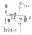
- FIG. 3is a schematic illustration of one embodiment of an ultra-wideband communication system employing a wired medium
- FIG. 4is a schematic illustration of a second embodiment of an ultra-wideband communication system employing a wired medium
- FIG. 5is an illustration of a power supply constructed according to one embodiment of the present invention.
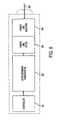
- FIG. 6is a schematic illustration of some of the components included in the power supply illustrated in FIG. 5 ;
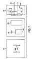
- FIG. 7is a front view, side view and internal schematic illustration of another embodiment of a power supply constructed according to the present invention.
- a traditional cable television provider, a community antenna television provider, a community access television provider, a cable television provider, a hybrid fiber-coax television provider, an Internet service provider, or any other provider of television, audio, voice and/or Internet datareceives broadcast signals at a central station, either from terrestrial cables, and/or from one or more antennas that receive signals from a communications satellite.
- the broadcast signalsare then distributed, usually by coaxial and/or fiber optic cable, from the central station to nodes located in business or residential areas.
- CATVcommunity access television provider
- HFCSHybrid Fiber-Coax Systems
- the analog coax systemsare typically characterized as pure analog systems. Pure analog CATV systems are characterized by their use of established NTSC/PAL (National Television Standards Committee/Phase Alternation Line) modulation onto a frequency carrier at 6 or 8 MHz intervals.
- NTSC/PALNational Television Standards Committee/Phase Alternation Line
- HFCSis a combination analog—digital topology employing both coaxial (analog) and fiber optic (digital) media that typically supports digitally modulated/encoded television channels above channel 78 .
- the analog channelsare modulated in 6 MHz allocations on channels 2 to 78 using frequencies from 55 to 547 MHz.
- digital channelstypically start at channel 79 and go as high as 136 and occupy a frequency range from 553 to 865 MHz.
- channel assignmentscan go as high as channel 158 or 997 MHz.
- the current ANSI/EIA-542-1997 standardonly defines and assigns channels to these limits.
- the actual wire/cable media itselfis generally capable of transmitting frequencies up to 3 GHz.
- the satellite downlinkIn both CATV and HFCS systems, typically the satellite downlink enters the cable company's head-end and the video, and/or other data streams are de-multiplexed out. Individual video data streams (either NTSC, MPEG, or any other suitable protocol) are extracted from the satellite downlink stream and routed to modulators specific for individual television channels. The outputs from each modulator are then combined into one broadband signal. From this point the combined channels are amplified and sent out, either by coaxial or fiber optic cable, to the customers.
- Individual video data streamsare extracted from the satellite downlink stream and routed to modulators specific for individual television channels.
- modulatorsspecific for individual television channels.
- the outputs from each modulatorare then combined into one broadband signal. From this point the combined channels are amplified and sent out, either by coaxial or fiber optic cable, to the customers.
- the broadband signalis modulated onto a fiber optic cable for distribution into the field, such as residential neighborhoods, or business districts.
- Modulation of the broadband signalis typically accomplished in one of two ways.
- the first methodthe entire broadband signal is sampled and digitized using a high speed Analog to Digital Converter (ADC).
- ADCAnalog to Digital Converter
- the datamust be sampled at a rate at least twice the highest frequency component to meet Nyquist minimum sampling requirements.
- the signalshould be sampled at 2.5 to 4 times the highest frequency, which entails sample rates of approximately 2 to 4 GHz.
- a parallel to serial converterthen shifts the parallel output data of the ADC into a serial format.
- the serial datadrives a laser diode for transmission over the fiber optic cable.
- the second methodis broadband block conversion where the entire spectrum of the broadband signal is modulated onto the fiber optic cable.
- Designated access nodesare located in neighborhoods, business districts and other areas.
- the access nodescontain a high speed Digital to Analog Converter (DAC) and a de-serializer.
- a fiber optic receiverdetects the laser-modulated signal at the access node.
- a parallel to serial converterde-serializes the data and it is feed to the high speed DAC.
- the datathen leaves the access node on standard 75 ohm, RG-6 or RG-8 or other suitable coax cable and is distributed to the customer's premises.
- the broadband signalis extracted from the fiber optic cable and transferred to a coaxial cable that connects to individual homes, apartments, businesses, universities, and other customers.
- the digital channels that generally reside on CATV channels 79 and higherare fundamentally different than the analog channels that generally reside on channels 2 through 78 .
- the analog channelsare comprised of modulated frequency carriers.
- the digital channelswhich generally use the 6 MHz allocation system, are digitally modulated using Quadrature Amplitude Modulation (QAM).
- QAMis a method of combining two amplitude modulated signals into a single channel, thereby doubling the effective bandwidth.
- In a QAM signalthere are two carriers, each having the same frequency but differing in phase by 90 degrees.
- the two modulated carriersare combined for transmission, and separated after transmission.
- QAM 16transmits 16 bits per signal, QAM 32, 64, and 256 each transmit 32, 54 and 256 bits per signal, respectively.
- QAMwas developed to support additional video streams encoded with MPEG video compression.
- Conventional CATV and HFCS networksmay employ QAM levels up to QAM 64 to enable up to 8 independent, substantially simultaneous MPEG video streams to be transmitted.
- the coaxial cableis connected to either a set-top box or directly to a television.
- the receiving devicethen de-multiplexes and de-modulates the video, audio, voice, Internet or other data.
- a televisioncan directly receive the analog signal, a set-top box is generally required for reception of the digitally encoded channels residing on CATV channels 79 and higher.
- the conventional wisdom for overcoming this limitationis to boost the power (i.e., increase the voltage of the signal) at the transmitter to boost the voltage level of the signal relative to the noise at the receiver. Without boosting the power at the transmitter, the receiver is unable to separate the noise from the desired signal.
- the overall performance of wired media systemsis still significantly limited by the accompanying noise that is inherent in wired media.
- the present inventionmay be employed in any type of network that uses wired media, in whole, or in part. That is, a network may use both wired media, such as coaxial cable, and wireless devices, such as satellites.
- a networkis a group of points or nodes connected by communication paths. The communication paths may be connected by wires, or they may be wirelessly connected.
- a network as defined hereincan interconnect with other networks and contain subnetworks.
- a network as defined hereincan be characterized in terms of a spatial distance, for example, such as a local area network (LAN), a metropolitan area network (MAN), and a wide area network (WAN), among others.
- a network as defined hereincan also be characterized by the type of data transmission technology in use on it, for example, a TCP/IP network, and a Systems Network Architecture network, among others.
- a network as defined hereincan also be characterized by whether it carries voice, data, or both kinds of signals.
- a network as defined hereincan also be characterized by who can use the network, for example, a public switched telephone network (PSTN), other types of public networks, and a private network (such as within a single room or home), among others.
- PSTNpublic switched telephone network
- a network as defined hereincan also be characterized by the usual nature of its connections, for example, a dial-up network, a switched network, a dedicated network, and a nonswitched network, among others.
- a network as defined hereincan also be characterized by the types of physical links that it employs, for example, optical fiber, coaxial cable, a mix of both, unshielded twisted pair, and shielded twisted pair, among others.
- the present inventionemploys a “carrier free” architecture which does not require the use of high frequency carrier generation hardware, carrier modulation hardware, stabilizers, frequency and phase discrimination hardware or other devices employed in conventional frequency domain communication systems.
- the present inventiondramatically increases the bandwidth of conventional networks that employ wired media, but can be inexpensively deployed without extensive modification to the existing wired media network.
- the present inventionprovides increased bandwidth by injecting, or otherwise super-imposing an ultra-wideband (UWB) signal into the existing data signal and subsequently recovers the UWB signal at an end node, set-top box, subscriber gateway, or other suitable location.
- Ultra-wideband, or impulse radioemploys pulses of electromagnetic energy that are emitted at nanosecond or picosecond intervals (generally tens of picoseconds to a few nanoseconds in duration). For this reason, ultra-wideband is often called “impulse radio.” Because the excitation pulse is not a modulated waveform, UWB has also been termed “carrier-free” in that no apparent carrier frequency is evident in the radio frequency (RF) spectrum. That is, the UWB pulses are transmitted without modulation onto a sine wave carrier frequency, in contrast with conventional radio frequency technology. Ultra-wideband requires neither an assigned frequency nor a power amplifier.
- Conventional radio frequency technologyemploys continuous sine waves that are transmitted with data embedded in the modulation of the sine waves' amplitude or frequency.
- a conventional cellular phonemust operate at a particular frequency band of a particular width in the total frequency spectrum.
- the Federal Communications Commissionhas allocated cellular phone communications in the 800 to 900 MHz band.
- Cellular phone operatorsuse 25 MHz of the allocated band to transmit cellular phone signals, and another 25 MHz of the allocated band to receive cellular phone signals.
- FIG. 1Another example of a conventional radio frequency technology is illustrated in FIG. 1 .
- 802.11 aa wireless local area network (LAN) protocol, transmits radio frequency signals at a 5 GHz center frequency, with a radio frequency spread of about 5 MHz.
- LANlocal area network
- a UWB pulsemay have a 1.8 GHz center frequency, with a frequency spread of approximately 4 GHz, as shown in FIG. 2 , which illustrates two typical UWB pulses.
- FIG. 2illustrates that the narrower the UWB pulse in time, the higher its center frequency and the broader the spread of its frequency spectrum. This is because frequency is inversely proportional to the time duration of the pulse.
- a 600 picosecond UWB pulsewill have about a 1.8 GHz center frequency, with a frequency spread of approximately 4 GHz.
- a 300 picosecond UWB pulsewill have about a 3 GHz center frequency, with a frequency spread of approximately 8 GHz.
- UWB pulsesgenerally do not operate within a specific frequency, as shown in FIG. 1 .
- UWB communication systemsallow communications at very high data rates, such as 100 megabits per second or greater.
- the UWB pulseis spread across an extremely wide frequency range, the power sampled at a single, or specific frequency is very low. For example, a UWB one-watt signal of one nano-second duration spreads the one-watt over the entire frequency occupied by the pulse.
- the UWB pulse power presentis one nano-watt (for a frequency band of 1 GHz). This is well within the noise floor of any wired media system and therefore does not interfere with the demodulation and recovery of the original CATV signals.
- the multiplicity of UWB pulsesare transmitted at relatively low power (when sampled at a single, or specific frequency), for example, at less than ⁇ 30 power decibels to ⁇ 60 power decibels, which minimizes interference with conventional radio frequencies.
- UWB pulses transmitted through most wired mediawill not interfere with wireless radio frequency transmissions. Therefore, the power (sampled at a single frequency) of UWB pulses transmitted though wired media may range from about +30 dB to about ⁇ 90 dB.
- a CATV systemgenerally employs a coaxial cable that transmits analog data on a frequency carrier.
- AMamplitude modulation
- QAMquadrature modulation
- UWB signalscan coexist in this environment without interference.
- AMthe data signal M(t) is multiplied with a cosine at the carrier frequency.
- an “in phase” and “quadrature” carrierscan carry data signals Mc(t) and Ms(t).
- an UWB systemtransmits a narrow time domain pulse, and the signal power is generally evenly spread over the entire bandwidth occupied by the signal.
- the UWB pulse power presentis one nano-watt (for a frequency band of 1 GHz). This is well within the noise floor of any wired media system and therefore does not interfere with the demodulation and recovery of the original AM or QAM data signals.
- Wired media communication systemssuffer from performance limitations caused by signal interference, ambient noise, and spurious noise. These limitations affect the available bandwidth, distance, and carrying capacity of the wire media system. With wired communication systems, the noise floor and signal interference in the wired media rapidly overcome the transmitted carrier signal. This noise on the wired media is a significant limitation to the ability of the system to increase bandwidth. UWB technology makes use of the noise floor to transmit data, without interfering with the carrier signal. Moreover, UWB transmitted through a wired medium has distinct advantages over its use in a wireless environment. In a wired environment there are no concerns with intersymbol interference, and there are no concerns relating to multi-user interference.
- CATV channelstypically occupy 6 MHz in the US and 8 MHz in Europe. These channels are arranged in a re-occurring pattern beginning at approximately 50 MHz and dependent on the CATV system, extend upward to 550 MHz, 750 MHz, 870 MHz, 1 GHz and higher.
- the present inventionis capable of injecting UWB pulses into the existing CATV infrastructure. These UWB signals do not interfere or degrade existing frequency domain signals. Additionally, the UWB signals can carry vast amounts of information with digital meaning in the time domain.
- the present inventionprovides an apparatus and method to enable any wired media network to augment their available bandwidth.
- this additional bandwidthis obtained by introducing UWB signals into the existing data transmission chain prior to broadcast from the system operator's head-end.
- the head-endmay include several components, such as the antenna farm 15 , the satellite receivers 20 , the channel modulator 25 , the combiner 30 , and the fiber optic transmitter/receiver 35 .
- UWB signalsmay be introduced into the wired media network at other locations, such as at the Internet router 90 or at the host digital terminal 80 , or at any other suitable location.
- the present inventionprovides UWB communication across fiber optic and coaxial cable, twisted pair wires, or any other type of conductive wire.
- a wired media networkwill be able to both transmit and receive digital information for the purposes of telephony, high-speed data, video distribution, video conferencing, wireless base operations and other similar purposes.
- the wired ultra-wideband communication system 10is configured to transmit ultra-wideband signals over an existing network or system that includes wired media.
- the wired ultra-wideband (UWB) system 10may transmit UWB signals over an existing community access television network (CATV), an optical network, a cable television network, a community antenna television network, a hybrid fiber-coax television network, an Internet service provider network, a PSTN network, a WAN, LAN, MAN, TCP/IP network, a college campus, town, city, or any other type of network as defined above, that employs wired media, in whole or in part.
- CATVcommunity access television network
- an optical networka cable television network
- a community antenna television networka hybrid fiber-coax television network
- an Internet service provider networka PSTN network
- WANwide area network
- LANlocal area network
- MANWireless Fidelity
- TCP/IP networka college campus, town, city, or any other type of network as defined above, that employs wire
- An antenna farm 15receives audio, video and data information from one or more satellites (not shown). Additional data may be received by terrestrial cables and wires, and by terrestrial wireless sources, such as a multichannel multipoint distribution service (MMDS). The data is then forwarded to the satellite receivers 20 that demodulate the data into separate audio, video and data streams. This information is forwarded to the channel modulators 25 that receive the program signals, such as CNN or MTV. The channel modulators 25 mix each signal with a radio frequency (RF) and assign a station number (such as 2 to 99 ) that each program will be received on by subscribers.
- RFradio frequency
- the multiple RF signalsare then forwarded to a combiner 30 that combines the multiple signals into a single output. That is, the combiner 30 receives the program signals from the channel modulators 25 and combines them onto a single coax cable and forwards the signal to the fiber optic transmitter/receiver 35 .
- the above-described arrangement and function of channel modulators 25 and combiners 30may vary with each type of wired media network.
- Additional audio, video, or other data signals received from either the antenna farm 15 or from terrestrial sources such as fiber optic or coaxial cablescan be routed from the satellite receiver 20 to the service provider ultra-wideband (UWB) device 40 .
- the service provider UWB device 40converts the audio, video, or other data signals received from the satellite receiver 20 into a multiplicity of UWB electromagnetic pulses.
- the service provider ultra-wideband (UWB) device 40may include several components, including a controller, digital signal processor, an analog coder/decoder, one or more devices for data access management, and associated cabling and electronics.
- the service provider ultra-wideband (UWB) device 40may include some, or all of these components, other necessary components, or their equivalents.
- the controllermay include error control, and data compression functions.
- the analog coder/decodermay include an analog to digital conversion function and vice versa.
- the data access management device or devicesmay include various interface functions for interfacing to wired media such as phone lines and coaxial cables.
- the digital signal processor in the service provider ultra-wideband (UWB) device 40modulates the audio, video, or other data signals received from the satellite receiver 20 into a multiplicity of UWB electromagnetic pulses, and may also demodulate UWB pulses received from the subscriber.
- modulationis the specific technique used to encode the audio, video, or other data into a multiplicity of UWB pulses.
- the digital signal processormay modulate the received audio, video, or other data signals into a multiplicity of UWB pulses that may have a duration that may range between about 0.1 nanoseconds to about 100 nanoseconds, and may be transmitted at relatively low power, for example, at less than ⁇ 30 power decibels to ⁇ 60 power decibels, as measured across the transmitted frequency.
- the UWB pulse duration and transmitted powermay vary, depending on several factors. Different modulation techniques employ different UWB pulse timing, durations and power levels.
- One example of a pulse position modulation systemmay transmit approximately 10,000 pulses per second. This system may transmit groups of pulses 100 picoseconds early or 100 picoseconds late to signify a specific digital bit, such as a “0” or a “1”. In this fashion a large amount of data may be transmitted across a wired medium.
- the UWB signalmay be transmitted in a fashion similar to that described in U.S.
- Pulse amplitude modulationemploys pulses of different amplitude to transmit data. Pulses of different amplitude may be assigned different digital representations of “0” or “1.”
- Other envisioned modulation techniquesinclude On-Off Keying that encodes data bits as pulse (1) or no pulse (0), and Binary Phase-Shift Keying (BPSK), or bi-phase modulation. BPSK modulates the phase of the signal (0 degrees or 180 degrees), instead of modulating the position. Spectral Keying, which is neither a PPM nor PAM modulation technique may also be employed. It will be appreciated that other modulation techniques, currently existing or yet to be conceived, may also be employed.
- a preferred modulation techniquewill optimize signal coexistence and pulse reliability by controlling transmission power, pulse envelope shape and Pulse Recurrent Frequencies (PRF).
- PRFPulse Recurrent Frequencies
- Both pseudo-random and fixed PRFsmay be used, with the knowledge that a fixed PRF may create a “carrier-like frequency,” which it and its higher order harmonics may interfere with the data carried in conventional RF carrier channels.
- a pseudo-random PRFthe difficulties encountered with a fixed PRF are usually avoided.
- One embodiment of a pseudo-random PRF modulation techniquemay include a UWB pulse envelope that is shaped to pre-amplify and compensate for high frequency components that the wired media may naturally attenuate.
- UWB pulse envelope shapinghas the additional advantage of controlling the power spectral density of the transmitted data stream.
- Wireless UWB transmissionsmust consider such issues as Inter-Symbol Interference (ISI) and Multi-User Interference (MUI), both of which can severely limit the bandwidth of UWB transmissions.
- Some modulation techniquessuch as Pulse Amplitude Modulation (PAM), which offer the ability for high bit densities are not effective at long wireless distances.
- PAMPulse Amplitude Modulation
- no multipath issuesarise and there are no propagation delay problems present in a wired medium. Therefore, it is estimated that an ultra-wideband system may be able to transmit data across a wired medium in a range from 100 Mbit/second to 1 Gbit/second. This data rate will ensure that the bandwidth requirements of any service provider can be met.
- a preferred embodiment of the service-provider UWB device 40will spread the signal energy of the UWB data stream across the a bandwidth that may ranger from 50 MHz to approximately 870 MHz or as discussed above, to 1 GHz, or higher. This will ensure that the signal energy present at any frequency is significantly below the normal noise floor for that frequency band, further ensuring coexistence with conventional RF carrier data.
- a UWB pulsewould have a duration of about 1 nano-second in a UWB data stream that has a 1 GHz bandwidth.
- the UWB pulse durationwould be tailored to match the available frequency of the specific network.
- an ideal UWB pulsewould generally be about 0.5 to 2 nano-seconds in duration. This is because a conventional CATV or HFCS network located in the United States typically utilizes a maximum frequency of approximately 870 MHz, but has the capacity to utilize up to 1 GHz. This bandwidth allows for a 1 to 2 nano-second pulse duration.
- a narrow pulse widthis preferred because more pulses can be transmitted in a discrete amount of time.
- Pulse widths of up to 2 nano-secondsmay be employed to guarantee pulse integrity throughout digitization, transmission, reception and reformation at the UWB subscriber device 50.
- an idealized pulse widthwould be calculated based on the frequency response of the specific wired media system.
- the multiplicity of generated UWB pulsesare sent from the service-provider UWB device 40 to the combiner 30 , which combines the UWB pulses with the conventional RF carrier signals.
- One method to accomplish this taskis to couple a wire carrying the conventional RF carrier signals to a standard coaxial splitter.
- a second wire carrying the UWB pulsesis also coupled to the standard coaxial splitter.
- the combined signalsare forwarded to the fiber optic transmitter/receiver 35 .
- the fiber optic transmitter/receiver 35converts both the multiplicity of UWB pulses and the conventional RF carrier signals received from the combiner 30 into a corresponding optical signal.
- the optical signal generatorcan be either a light-emitting diode, solid state laser diode, or other suitable device.
- the optical signalis then distributed on fiber optic cables to residential neighborhoods, business districts, universities, colleges or other locations for distribution to subscribers and customers.
- Other methods and techniques for combining a UWB pulse stream and a conventional RF carrier signal streammay also be employed.
- the UWB pulse streammy be sent directly to the fiber optic transmitter/receiver 35 , which will then combine the two signals.
- a fiber multiplexer node 45may be located at any one of the locations described above.
- the optical signalsare received by the multiplexer 45 and are converted back to the combined conventional RF carrier and UWB pulsed signals.
- the combined signalsare forwarded to a subscriber UWB device 50 .
- the subscriber UWB device 50can be considered a gateway or router that provides access to the combined signals.
- the subscriber UWB device 50will demodulate the multiplicity of UWB electromagnetic pulses back into a conventional RF carrier signal.
- the subscriber UWB device 50may include all, some or additional components found in the service provider UWB device 40 . In this manner, additional bandwidth will be available to the wired media network to provide the additional data and functionality demanded by the customer.
- FIG. 4An alternative embodiment of the present invention is illustrated in FIG. 4 .
- a full service wired UWB communication system 70is structured to allow for extremely high data rate transmission of video, telephone, internet and audio signals.
- the full service UWB system 70receives audio, video and data information from an antenna farm 15 or from terrestrial sources such as fiber optic or coaxial cables. These signals are forwarded to the satellite receivers 20 as described above with reference to the wired UWB communication system 10 .
- signals from a public telephone network 75are received by a host digital terminal 80 .
- the host digital terminal 80modulates multiple voice signals into two-way upstream and downstream RF signals.
- the voice signals from the host digital terminal 80are forwarded to the service provider UWB device 40 .
- An internet service provider 85forwards internet data to the internet router 90 .
- the internet router 90generates packets, such as TCP/IP packets, which are forwarded to the service provider UWB device 40 .
- the service provider UWB device 40modulates the internet data, the telephony data and the data received from the satellite receivers 20 into a multiplicity of electromagnetic pulses, as described above, and forwards the pulses to the combiner 30 .
- the combinercombines the UWB pulses with the conventional RF carrier signals and forwards the combined signal to the fiber optic transmitter/receiver 35 .
- the signalsare then converted into an optical signal by either a light emitting diode, solid state laser diode, or other suitable device.
- the optical signalis then distributed to the fiber multiplexer node 45 located within business districts, residential neighborhoods, universities, colleges and other areas.
- the fiber multiplexer node 45receives the fiber optic signal and converts them back to the combined conventional RF carrier and UWB pulsed signals.
- the combined signalsare forwarded to a subscriber UWB device 50 .
- the subscriber UWB device 50can be considered a gateway or router that provides access to the combined signals.
- the subscriber UWB device 50demodulates the multiplicity of UWB electromagnetic pulses into RF signals and forwards the RF signals to appropriate locations such as televisions, personal computers or telephones.
- subscriber UWB devices 50may be located adjacent to televisions sets similar to a set-top box and used to transmit on-demand movies, internet access or pay-per-view programs.
- Yet another embodiment of the present inventionmay include a UWB device 50 that may be located within a television set, or computer.
- the UWB device 50is constructed to convert and distribute data to computers, network servers, digital or subscription televisions, interactive media devices such as set-top boxes and telephone switching equipment.
- the subscriber UWB device 50may also be configured to transmit UWB pulses wirelessly to provide audio, video, and other data content to personal computers, televisions, PDAs, telephones and other devices.
- UWB device 50may include the necessary components to transmit and receive UWB or conventional RF carrier signals to provide access to interfaces such as PCI, PCMCIA, USB, Ethernet, IEEE1394, or other interface standards.
- the present inventionwill also allow for data to be transmitted “upstream” toward the service provider.
- a conventional CATV or HFCS networkreserves frequencies below 50 MHz for upstream traffic.
- One embodiment of the present inventionmay include a band-pass filter with stop-bands above 1 GHz, and below 50 MHz to ensure attenuation of UWB pulses so as not to interfere with upstream traffic. These filters also serve the purpose of limiting potential inter-modulation distortion that could be introduced by the UWB pulses.
- UWB transmitter/receivermay transmit UWB pulses through traditional telephone wires.
- an UWB transmitter/receivercan be located in a regional center, sectional center, primary center, toll center, end-office, or their equivalents.
- the present invention of transmitting ultra-wideband signals across a wired mediumcan employ any type of wired media.
- the wired mediacan include optical fiber ribbon, fiber optic cable, single mode fiber optic cable, multi-mode fiber optic cable, plenum wire, PVC wire, and coaxial cable.
- the wired mediacan include twisted-pair wiring, whether shielded or unshielded.
- Twisted-pair wiremay consist of “pairs” of color-coded wires. Common sizes of twisted-pair wire are 2 pair, 3 pair, 4 pair, 25 pair, 50 pair and 100 pair. Twisted-pair wire is commonly used for telephone and computer networks. It comes in ratings ranging from category 1 to category 7. Twisted-pair wiring also is available unshielded. That is, the wiring does not have a foil or other type of wrapping around the group of conductors within the jacket. This type of wiring is most commonly used for wiring for voice and data networks.
- the foregoing list of wired mediais meant to be exemplary, and not exclusive.
- the present inventioncan provide additional bandwidth to enable the transmission of large amounts of data over an existing wired media network, whether the wired media network is a Internet service provider, cable television provider, or a computer network located in a business or university.
- the additional bandwidthcan allow consumers to receive the high speed Internet access, interactive video and other features that they are demanding.
- UWBultra-wideband
- an UWB enabled power supply sourcesuch as a power strip, or other type of power supply device can power consumer devices. Devices powered by this UWB enabled power supply source can communicate with other devices that are commonly powered by the power supply source.
- power line filteringmay be employed to reduce the inherent noise within the power supply source.
- UWB pulse contentcan be isolated to within the power supply source.
- One feature of this embodimentis that it employs UWB technology to overcome some of the limitations inherent in conventional power line communication (PLC) systems.
- the present inventiontransmits a time domain pulse or signal that distributes the signal energy relatively evenly throughout the entire spectrum of the medium.
- FDMfrequency division multiplexing
- OFDMorthogonal frequency division multiplexing
- the spectral density of UWBis extremely low. Like other spread-spectrum technologies this enhances the noise immunity of the transmission, increasing signal reliability. Unlike other spread-spectrum technologies, avoidance of other frequencies of transmission is unnecessary.
- One feature of this embodiment of the present inventionincludes methods of communication based on the inherent distortion effects of the media.
- This embodiment of the present inventionmay be employed in any type of network, as defined above, that uses electrical power lines, be it wireless, wired, or a mix of wire media and wireless components.
- the present inventiondramatically increases the bandwidth of conventional networks that employ wire media, but can be inexpensively deployed without extensive modification to the existing wire media network.
- a central facet of any data communications systemis the reliability and integrity of the data that is being communicated.
- the data that is transmitted from the transmitting locationshould be identical to the data that is received at the receiving location.
- the data that is received at the receiving locationis oftentimes corrupted.
- Data corruption, or other data communication errorsmay be attributed to the transmission equipment, and/or the transmission medium and/or the receiving equipment. With respect to the transmission medium, data errors are usually attributed to the characteristics associated with the particular transmission medium.
- the transmission of data over wire mediagenerally suffers from noise and attenuation phenomena.
- an alternating current (AC) power lineis used as the transmission medium
- this type of mediumgenerally exhibits unpredictable transmission characteristics such as extreme attenuation at certain frequencies, phase changes along the transmission route, notches (dips in frequency response) and discontinuities (changes in impedance).
- Gaussian noisethere are three modes of noise most common: Gaussian noise, low voltage impulsive interference, and very high voltage spikes.
- the low voltage impulsive interferencetends to be the predominant cause of data transmission errors. Therefore, data transmission may be reliably accomplished though power lines even in the presence of Gaussian noise.
- high voltage spikesthey are relatively infrequent and invariably cause data errors, with error detection/retransmission (ACK/NACK) being commonly recognized as the best method of recovering the lost information.
- ACK/NACKerror detection/retransmission
- such electrical load variationmay be caused by power draw from virtually any type of electrical device, such as industrial machines, electric motors in household and commercial appliances, light dimmer circuits, heaters, battery chargers, computers, video monitors, audio equipment, and any other device that requires electricity to operate.
- electrical devicesuch as industrial machines, electric motors in household and commercial appliances, light dimmer circuits, heaters, battery chargers, computers, video monitors, audio equipment, and any other device that requires electricity to operate.
- Narrowband transmission formatssuch as frequency shift keying (FSK) or amplitude shift keying (ASK) are somewhat immune to frequency dependent attenuation, and thus may suffer little or no distortion.
- FSKfrequency shift keying
- ASKamplitude shift keying
- Wideband transmission formatssuch as spread spectrum are less susceptible to the signal degradation caused by narrowband attenuation null.
- the spread spectrum signalexperiences more distortion due to frequency dependent attenuation.
- a conventional narrowband signaling formatis susceptible to attenuation while a conventional wideband signaling format is susceptible to distortion.
- Orthogonal frequency division multiplexingis a method of digital modulation in which a signal is split into several narrow band channels at different frequencies.
- the standard approach to OFDMis to use the same data allocation to all frequencies, similar to the IEEE 802.11 a standard.
- this type of data allocation schemeis undesirable in power line media since some frequencies are severely attenuated.
- a conventional fix to this problemis to allow the transmitter and receiver to adapt to the characteristics of the channel. But this approach dramatically increases the complexity and cost of this form of communication.
- Yet another method for transmitting data through power linesis frequency division multiplexing (FDM) and time division multiplexing (TDM).
- FDMfrequency division multiplexing
- TDMtime division multiplexing
- UWBultra-wideband
- the UWB datastreamshould be reliably transmitted and recovered. Additionally, the UWB signal, or pulses should peacefully coexist within the existing spectral content on the system.
- ultra-wideband pulsesmay generally have a duration of about 1 nano-second. Although they may range in duration from about 0.1 to about 100 nano-seconds, a preferred range may be between about 0.5 to about 2 nano-seconds in duration.
- the current allocations by the two European standards organizations (ETSI and Cenelec)show utilization of a maximum frequency of approximately 30 MHz in a power line. This bandwidth allows for a 33 nano-second pulse duration.
- ETSI and CenelecEuropean standards organizations
- UWB pulse durationis preferred since more UWB pulses can be transmitted in a discrete amount of time.
- UWB pulse durationmay have to be expanded up to about 40 to 50 nano-seconds to ensure pulse integrity throughout digitization, transmission, reception and reformation at the receiver.
- the ideal UWB pulse durationmay be calculated based on the frequency response of the media to maintain signal integrity.
- signal coexistence and pulse reliabilitymay be optimized by controlling transmission power, pulse envelope shape and the pulse recurrence frequency (PRF).
- PRFpulse recurrence frequency
- a fixed PRFmay be used, but care needs to be exercised in selecting the transmission rate to avoid establishing a “carrier” like frequency which it and its higher order harmonics may cause interference with data carried in other frequency channels.
- PRFpulse recurrence frequency
- the UWB pulse envelopeis shaped to pre-amplify and compensate for high frequency components that the transmission media may naturally attenuate. Pulse envelope shaping has the additional advantage of controlling the power spectral density of the transmitted data stream.
- the UWB pulse amplitudemay also be optimized to ensure reliable UWB pulse transmission through the communication system.
- Another feature of the present inventionis that spreading the signal energy of the UWB data stream across the available bandwidth (which may be greater than or less than 30 MHz) generally ensures that the signal energy present at any frequency is below the noise floor for that frequency band, which further ensures coexistence with data signals that may be present.
- Wire mediasuch as electrical power lines provides an ideal environment for bandwidth optimization.
- wireless mediasuch issues as multi-path interference (MPI), and multi-user interference (MUI) must be addressed and can severely limit the bandwidth of UWB transmissions.
- MPImulti-path interference
- MUImulti-user interference
- modulation techniquessuch as pulse amplitude modulation (PAM), which offer the ability for high bit densities, are not effective at long ranges. Some of these characteristics do not apply to UWB transmitted through wire media.
- PAMpulse amplitude modulation
- ultra-wideband (UWB) communicationsoccur between devices that share a common power supply source, or power strip 201 .
- the common power supply sourcemay include the wiring and associated electrical power outlets in a home, business, university, hospital or other structure.
- the common power supply sourcemay be any other type of electrical power supply, such as a battery powered device that provides electric power to one or more UWB enabled devices.
- UWB enabled devicesreceive power from, and communicate with, each other through power outlet plugs 202 a–f .
- UWB enabled devicesare devices that include UWB communications technology, and may include devices such as a phone, a personal digital assistant, a portable computer, a laptop computer, any network as described above (LAN, WAN, PAN etc.), video monitors, computer monitors, or any other device employing UWB technology.
- power line filtersmay be employed to filter noise and other types of power line communications from the external power line. Additionally, Ultra-Wideband communications can be prevented from reaching the external power distribution system through plug 203 . Since the UWB pulses can be isolated from the rest of the power distribution, increased UWB power levels can be employed. This embodiment has the advantage of increased data rates between devices connected to the strip. But is limited to the number of communicating devices in that a common UWB power strip must power each communicating device.
- Isolator 304blocks other forms of power line communications from entering the power strip 201 .
- the isolatoris a bandpass filter with a center frequency of about 60 Hz. The filter rejects, or blocks ultra-wideband pulse content that is outside of the pass band of the filter. Additionally, the isolator 304 blocks the transmission of ultra-wideband pulses to the power source. Since most power sources, such as state or city electrical power distribution systems are inherently noisy, filter 303 is employed to filter the noise from the incoming electrical power.
- the filter 303may be a band-rejection filter, bandpass filter, highpass filter, lowpass filter or other suitable filter.
- the transceiver, or transceivers 302transmit and receive data to and from the devices connected to the power strip.
- the transceiver 302may be a transmitter-receiver containing separate components, or it may be an integrated transceiver that may include a pulse detector, a data modulation unit, a data demodulation unit, one or more filters, one or more amplifiers, and other components that enable the transmission and reception of ultra-wideband pulses.
- Another embodiment of the power strip 201may include a controller 301 that may perform functions such as routing and signal input and output (I/O) control.
- the controller 301may include a digital computer that may contain computer logic or software to perform the I/O functions.
- UWB pulses or signalsmay travel throughout the power lines in a structure.
- the UWB pulsesmay not be isolated from the structure's power source.
- a UWB isolatorsimilar to the isolator 304 described above, may be positioned at a main power transfer location for the structure, and thereby isolate the UWB pulses from the power source, such as a state or city electrical power line.
- the structurein this case may be a home, business, university, hospital or any other structure that employs or has a need for electrical power.
- a plug-in ultra-wideband (UWB) transceiver 401may be employed in any room, or other area of the structure that has electrical power outlets (not shown).
- the plug-in transceiver 401is removably coupled to the electrical power outlet by male connectors 407 .
- the male connectors 407may be electrically conductive pins or plugs, and they may be sized and configured to fit female power outlets of any configuration.
- the male connectors 407may be sized to fit a 110 volt, 3-slot power female outlet; a 110 volt, 2-slot female power outlet; a 220 volt, 240 volt or greater voltage female power outlet that may be configured for Continental Europe, Japan, or any other country.
- An UWB enabled device(not shown) is then removably coupled to the plug-in UWB transceiver 401 though female slots 402 .
- the female slots 402may be sized and configured to receive any arrangement of male pins or plugs. In this fashion, the plug-in transceiver 401 allows the UWB enabled device to obtain electrical power from the structure's power outlets.
- the plug-in UWB transceiver 401allows an UWB enabled device that is plugged into connectors 407 to communicate with other UWB devices through the structure's power lines.
- a UWB enabled devicemay receive wireless UWB pulses, or signals through the plug-in UWB transceiver 401 .
- the plug-in UWB transceiver 401may function as a communications bridge, by forwarding wireless UWB pulses, or signals through the power line to the UWB enabled device that is coupled to the plug-in UWB transceiver 401 .
- the plug-in UWB transceiver 401includes an ultra-wideband wire media transceiver 405 .
- a wireless-capable plug-in UWB transceiver 401may include a wireless transceiver 403 that has an ultra-wideband antenna 404 .
- the plug-in UWB transceiver 401may have a single transceiver (not shown) that includes an ultra-wideband antenna 404 , with the single transceiver constructed to transmit and receive both wired and wireless UWB pulses, or signals.
- the single transceiver, wire media transceiver 405 , and the wireless transceiver 405may be constructed like the transceiver 302 , shown in FIG. 6 .
Landscapes
- Engineering & Computer Science (AREA)
- Signal Processing (AREA)
- Computer Networks & Wireless Communication (AREA)
- Power Engineering (AREA)
- Multimedia (AREA)
- Physics & Mathematics (AREA)
- Electromagnetism (AREA)
- Two-Way Televisions, Distribution Of Moving Picture Or The Like (AREA)
- Cable Transmission Systems, Equalization Of Radio And Reduction Of Echo (AREA)
Abstract
Description
y(t)=m(t)Cos(ωct)
In a QAM based system multiple carrier signals are transmitted at the same carrier frequency, but at different phases. This allows multiple data signals to be simultaneously carried. In the case of two carriers, an “in phase” and “quadrature” carriers can carry data signals Mc(t) and Ms(t). The resultant signal y(t) can be represented as:
y(t)=Mc(t)Cos(ωct)+Ms(t)Sin(ωct)
Claims (31)
Priority Applications (3)
| Application Number | Priority Date | Filing Date | Title |
|---|---|---|---|
| US10/456,047US7027483B2 (en) | 2002-06-21 | 2003-06-06 | Ultra-wideband communication through local power lines |
| PCT/US2004/017752WO2005002065A2 (en) | 2003-06-06 | 2004-06-04 | Ultra-wideband communication through local power lines |
| EP04754372AEP1636913A4 (en) | 2003-06-06 | 2004-06-04 | Ultra-wideband communication through local power lines |
Applications Claiming Priority (2)
| Application Number | Priority Date | Filing Date | Title |
|---|---|---|---|
| US10/177,313US20030235236A1 (en) | 2002-06-21 | 2002-06-21 | Ultra-wideband communication through a wired medium |
| US10/456,047US7027483B2 (en) | 2002-06-21 | 2003-06-06 | Ultra-wideband communication through local power lines |
Related Parent Applications (1)
| Application Number | Title | Priority Date | Filing Date |
|---|---|---|---|
| US10/177,313Continuation-In-PartUS20030235236A1 (en) | 2002-06-21 | 2002-06-21 | Ultra-wideband communication through a wired medium |
Publications (2)
| Publication Number | Publication Date |
|---|---|
| US20040022304A1 US20040022304A1 (en) | 2004-02-05 |
| US7027483B2true US7027483B2 (en) | 2006-04-11 |
Family
ID=33551290
Family Applications (1)
| Application Number | Title | Priority Date | Filing Date |
|---|---|---|---|
| US10/456,047Expired - LifetimeUS7027483B2 (en) | 2002-06-21 | 2003-06-06 | Ultra-wideband communication through local power lines |
Country Status (3)
| Country | Link |
|---|---|
| US (1) | US7027483B2 (en) |
| EP (1) | EP1636913A4 (en) |
| WO (1) | WO2005002065A2 (en) |
Cited By (86)
| Publication number | Priority date | Publication date | Assignee | Title |
|---|---|---|---|---|
| US20050060474A1 (en)* | 2003-09-17 | 2005-03-17 | The Boeing Company | Centralized bus interface with single wire secondary distribution |
| US20050111636A1 (en)* | 1999-07-20 | 2005-05-26 | Serconet, Ltd | Network for telephony and data communication |
| US20060018338A1 (en)* | 1998-07-28 | 2006-01-26 | Serconet, Ltd. | Local area network of serial intelligent cells |
| US20060182094A1 (en)* | 2000-04-18 | 2006-08-17 | Serconet Ltd. | Telephone communication system over a single telephone line |
| US20060197428A1 (en)* | 2005-02-21 | 2006-09-07 | Takeshi Tonegawa | Electron devices with non-evaporation-type getters and method for manufacturing the same |
| US20070143078A1 (en)* | 2001-03-26 | 2007-06-21 | Martin Vetterli | Sampling method, reconstruction method, and device for sampling and/or reconstructing signals |
| US20070156927A1 (en)* | 2006-01-03 | 2007-07-05 | Asoka Usa Corporation | Power line outlet strip and method for powerline communications |
| US20070162964A1 (en)* | 2006-01-12 | 2007-07-12 | Wang Liang-Yun | Embedded system insuring security and integrity, and method of increasing security thereof |
| US20070242026A1 (en)* | 2006-04-14 | 2007-10-18 | Qualcomm Incorporated | Apparatus and method of pulse generation for ultra-wideband transmission |
| US20070248114A1 (en)* | 2006-04-20 | 2007-10-25 | Qualcomm Incorporated | Media access control for ultra-wide band communication |
| US20070249288A1 (en)* | 2006-04-14 | 2007-10-25 | Kamran Moallemi | Distance-based security |
| US20070259629A1 (en)* | 2006-04-26 | 2007-11-08 | Qualcomm Incorporated | Duty cycling power scheme |
| US20070259690A1 (en)* | 2006-04-14 | 2007-11-08 | Qualcomm Incorporated | Distance-based presence management |
| US20070257827A1 (en)* | 2006-04-20 | 2007-11-08 | Qualcomm Incorporated | Low power output stage |
| US20070279237A1 (en)* | 2006-04-26 | 2007-12-06 | Qualcomm Incorporated | Wireless localization apparatus and method |
| US20070281721A1 (en)* | 2006-04-26 | 2007-12-06 | Qualcomm Incorporated | Methods and apparatuses of initiating communication in wireless networks |
| US20070285306A1 (en)* | 2006-04-18 | 2007-12-13 | Qualcomm Incorporated | Verified distance ranging |
| US20070286274A1 (en)* | 2006-04-19 | 2007-12-13 | Qualcomm Incorporated | Apparatus and method of low latency multi-hop communication |
| US20080045161A1 (en)* | 2006-04-18 | 2008-02-21 | Qualcomm Incorporated | Waveform encoding for wireless applications |
| US20080112512A1 (en)* | 2006-11-15 | 2008-05-15 | Qualcomm Incorporated | Transmitted reference signaling scheme |
| US20080116941A1 (en)* | 2006-11-16 | 2008-05-22 | Qualcomm Incorporated | Peak signal detector |
| US20080117939A1 (en)* | 2006-11-16 | 2008-05-22 | Qualcomm Incorporated | Multiple access techniques for a wireless communiation medium |
| US20080117804A1 (en)* | 2006-11-16 | 2008-05-22 | Qualcomm Incorporated | Multiple access techniques for a wireless communication medium |
| US20080144560A1 (en)* | 2006-12-15 | 2008-06-19 | Qualcomm Incorporated | Channel access scheme for ultra-wide band communication |
| US20080240440A1 (en)* | 2007-03-27 | 2008-10-02 | Gregory Gordon Rose | Synchronization test for device authentication |
| US20080246548A1 (en)* | 2007-04-05 | 2008-10-09 | Qualcomm Incorporated | Method and apparatus for generating oscillating signals |
| US20080258562A1 (en)* | 2007-04-23 | 2008-10-23 | Qualcomm Incorporated | Apparatus and method for generating fine timing from coarse timing source |
| US20080262928A1 (en)* | 2007-04-18 | 2008-10-23 | Oliver Michaelis | Method and apparatus for distribution and personalization of e-coupons |
| US20080280569A1 (en)* | 2004-05-06 | 2008-11-13 | Serconet Ltd. | System and Method for Carrying a Wireless Based Signal Over Wiring |
| US7453895B2 (en) | 2001-10-11 | 2008-11-18 | Serconet Ltd | Outlet with analog signal adapter, a method for use thereof and a network using said outlet |
| US20090017782A1 (en)* | 2007-07-12 | 2009-01-15 | Pavel Monat | Method for determining line-of-sight (los) distance between remote communications devices |
| US20090016548A1 (en)* | 2007-07-10 | 2009-01-15 | Pavel Monat | Super regenerative (sr) apparatus having plurality of parallel sr amplifiers tuned to distinct frequencies |
| US20090021408A1 (en)* | 2007-07-18 | 2009-01-22 | Lee Chong U | Adaptive dynamic range control |
| US20090027175A1 (en)* | 2004-09-29 | 2009-01-29 | Aizo Ag | Data Transmission Method and Device for A/C Systems |
| US20090034591A1 (en)* | 2007-07-30 | 2009-02-05 | David Jonathan Julian | Method of pairing devices |
| US20090067407A1 (en)* | 2007-09-11 | 2009-03-12 | Qualcomm Incorporated | Keep-alive for wireless networks |
| US20090066704A1 (en)* | 2007-09-11 | 2009-03-12 | Wiquest Communications, Inc. | Wireless graphics card |
| US20090076911A1 (en)* | 2007-06-20 | 2009-03-19 | Dang Minh Vo | Mobile coupons utilizing peer to peer ranging |
| US20090076912A1 (en)* | 2007-06-20 | 2009-03-19 | Rajan Rajeev D | Management of dynamic electronic coupons |
| US20090080568A1 (en)* | 2007-09-21 | 2009-03-26 | Qualcomm Incorporated | Signal generator with adjustable phase |
| US20090080542A1 (en)* | 2007-09-25 | 2009-03-26 | Qualcomm Incorporated | Interference Mitigation For Impulse-Based Communication |
| US20090080101A1 (en)* | 2007-09-21 | 2009-03-26 | Qualcomm Incorporated | Signal generator with adjustable frequency |
| US20090086702A1 (en)* | 2007-09-28 | 2009-04-02 | Qualcomm Incorporated | Randomization of periodic channel scans |
| US7522615B2 (en) | 2002-11-13 | 2009-04-21 | Serconet, Ltd. | Addressable outlet, and a network using same |
| US20090224860A1 (en)* | 2008-03-10 | 2009-09-10 | Qualcomm Incorporated | System and method of using residual voltage from a prior operation to establish a bias voltage for a subsequent operation |
| US20090224832A1 (en)* | 2008-03-10 | 2009-09-10 | Qualcomm Incorporated | System and method of enabling a signal processing device in a relatively fast manner to process a low duty cycle signal |
| US20090243699A1 (en)* | 2008-03-25 | 2009-10-01 | Qualcomm Incorporated | System and method of companding an input signal of an energy detecting receiver |
| US20090251208A1 (en)* | 2008-04-08 | 2009-10-08 | Qualcomm Incorporated | Low power slicer-based demodulator for ppm |
| US20090259671A1 (en)* | 2008-04-15 | 2009-10-15 | Qualcomm Incorporated | Synchronizing timing mismatch by data insertion |
| US20090270030A1 (en)* | 2008-04-23 | 2009-10-29 | Qualcomm Incorporated | Multi-level duty cycling |
| US7633966B2 (en) | 2000-04-19 | 2009-12-15 | Mosaid Technologies Incorporated | Network combining wired and non-wired segments |
| US20090323985A1 (en)* | 2008-06-30 | 2009-12-31 | Qualcomm Incorporated | System and method of controlling power consumption in response to volume control |
| US20100005371A1 (en)* | 2008-07-07 | 2010-01-07 | Qualcomm Incorporated | System and method of puncturing pulses in a receiver or transmitter |
| US20100020863A1 (en)* | 2008-07-25 | 2010-01-28 | Qualcomm Incorporated | Determination of receive data values |
| US20100046443A1 (en)* | 2008-08-22 | 2010-02-25 | Qualcomm Incorporated | Addressing schemes for wireless communication |
| US7680255B2 (en) | 2001-07-05 | 2010-03-16 | Mosaid Technologies Incorporated | Telephone outlet with packet telephony adaptor, and a network using same |
| US7716001B2 (en) | 2006-11-15 | 2010-05-11 | Qualcomm Incorporated | Delay line calibration |
| US20100172393A1 (en)* | 2009-01-06 | 2010-07-08 | Qualcomm Incorporated | Pulse arbitration for network communications |
| US20100241816A1 (en)* | 2009-03-19 | 2010-09-23 | Qualcolmm Incorporated | Optimized transfer of packets in a resource constrained operating environment |
| US7813451B2 (en) | 2006-01-11 | 2010-10-12 | Mobileaccess Networks Ltd. | Apparatus and method for frequency shifting of a wireless signal and systems using frequency shifting |
| US7855611B2 (en) | 2006-11-15 | 2010-12-21 | Qualcomm Incorporated | Delay line calibration |
| US7873058B2 (en) | 2004-11-08 | 2011-01-18 | Mosaid Technologies Incorporated | Outlet with analog signal adapter, a method for use thereof and a network using said outlet |
| US20110026621A1 (en)* | 2009-08-03 | 2011-02-03 | Texas Instruments Incorporated | Ofdm transmission methods in three phase modes |
| US20110129099A1 (en)* | 2007-08-28 | 2011-06-02 | Qualcomm Incorporated | Apparatus and method for modulating an amplitude, phase or both of a periodic signal on a per cycle basis |
| US7965805B2 (en) | 2007-09-21 | 2011-06-21 | Qualcomm Incorporated | Signal generator with signal tracking |
| US20110231657A1 (en)* | 2009-03-16 | 2011-09-22 | Qualcomm Incorporated | Apparatus and method for employing codes for telecommunications |
| US8175649B2 (en) | 2008-06-20 | 2012-05-08 | Corning Mobileaccess Ltd | Method and system for real time control of an active antenna over a distributed antenna system |
| US8405488B1 (en)* | 2008-10-21 | 2013-03-26 | Universal Lighting Technologies, Inc. | System and method for encoding ballast control signals |
| US8483639B2 (en) | 2008-05-06 | 2013-07-09 | Qualcomm Incorporated | AGC for slicer-based low power demodulator |
| US8514911B2 (en) | 2009-05-13 | 2013-08-20 | Qualcomm Incorporated | Method and apparatus for clock drift compensation during acquisition in a wireless communication system |
| US8538345B2 (en) | 2007-10-09 | 2013-09-17 | Qualcomm Incorporated | Apparatus including housing incorporating a radiating element of an antenna |
| US8582598B2 (en) | 1999-07-07 | 2013-11-12 | Mosaid Technologies Incorporated | Local area network for distributing data communication, sensing and control signals |
| US8594133B2 (en) | 2007-10-22 | 2013-11-26 | Corning Mobileaccess Ltd. | Communication system using low bandwidth wires |
| US8600373B2 (en) | 2006-04-26 | 2013-12-03 | Qualcomm Incorporated | Dynamic distribution of device functionality and resource management |
| US8840266B1 (en)* | 2012-02-03 | 2014-09-23 | Paris Incorporated | Modular power-delivery system |
| US8886125B2 (en) | 2006-04-14 | 2014-11-11 | Qualcomm Incorporated | Distance-based association |
| US8897215B2 (en) | 2009-02-08 | 2014-11-25 | Corning Optical Communications Wireless Ltd | Communication system using cables carrying ethernet signals |
| US9083448B2 (en) | 2007-10-26 | 2015-07-14 | Qualcomm Incorporated | Preamble capture and medium access control |
| US9141961B2 (en) | 2007-06-20 | 2015-09-22 | Qualcomm Incorporated | Management of dynamic mobile coupons |
| US9142961B1 (en) | 2010-09-10 | 2015-09-22 | The United States Of America As Represented By The Administrator Of National Aeronautics And Space Administration | Apparatus and method for communication over power lines |
| US9184960B1 (en) | 2014-09-25 | 2015-11-10 | Corning Optical Communications Wireless Ltd | Frequency shifting a communications signal(s) in a multi-frequency distributed antenna system (DAS) to avoid or reduce frequency interference |
| US9338823B2 (en) | 2012-03-23 | 2016-05-10 | Corning Optical Communications Wireless Ltd | Radio-frequency integrated circuit (RFIC) chip(s) for providing distributed antenna system functionalities, and related components, systems, and methods |
| US9483769B2 (en) | 2007-06-20 | 2016-11-01 | Qualcomm Incorporated | Dynamic electronic coupon for a mobile environment |
| US9660680B1 (en) | 2011-08-26 | 2017-05-23 | The United States Of America As Represented By The Administrator Of National Aeronautics And Space Administration | Apparatus and method for communication over power lines |
| US10542372B2 (en) | 2011-03-15 | 2020-01-21 | Qualcomm Incorporated | User identification within a physical merchant location through the use of a wireless network |
| US10986165B2 (en) | 2004-01-13 | 2021-04-20 | May Patents Ltd. | Information device |
Families Citing this family (36)
| Publication number | Priority date | Publication date | Assignee | Title |
|---|---|---|---|---|
| US20040218688A1 (en)* | 2002-06-21 | 2004-11-04 | John Santhoff | Ultra-wideband communication through a power grid |
| US7474705B2 (en)* | 2002-08-16 | 2009-01-06 | Wisair Ltd | Scalable ultra-wide band communication system |
| GB2393370B (en)* | 2002-10-02 | 2004-10-20 | Artimi Ltd | Communication methods & apparatus |
| WO2004032277A1 (en)* | 2002-10-02 | 2004-04-15 | Artimi Ltd | Communication methods and apparatus |
| US6980091B2 (en)* | 2002-12-10 | 2005-12-27 | Current Technologies, Llc | Power line communication system and method of operating the same |
| US6965303B2 (en)* | 2002-12-10 | 2005-11-15 | Current Technologies, Llc | Power line communication system and method |
| US9337948B2 (en) | 2003-06-10 | 2016-05-10 | Alexander I. Soto | System and method for performing high-speed communications over fiber optical networks |
| US20050084033A1 (en)* | 2003-08-04 | 2005-04-21 | Lowell Rosen | Scalable transform wideband holographic communications apparatus and methods |
| US20050100076A1 (en)* | 2003-08-04 | 2005-05-12 | Gazdzinski Robert F. | Adaptive holographic wideband communications apparatus and methods |
| US20050084032A1 (en)* | 2003-08-04 | 2005-04-21 | Lowell Rosen | Wideband holographic communications apparatus and methods |
| US7092693B2 (en)* | 2003-08-29 | 2006-08-15 | Sony Corporation | Ultra-wide band wireless / power-line communication system for delivering audio/video content |
| US7171506B2 (en)* | 2003-11-17 | 2007-01-30 | Sony Corporation | Plural interfaces in home network with first component having a first host bus width and second component having second bus width |
| US7113134B1 (en) | 2004-03-12 | 2006-09-26 | Current Technologies, Llc | Transformer antenna device and method of using the same |
| US7432847B2 (en)* | 2004-06-03 | 2008-10-07 | Wireless 2000 Rf & Uwb Technologies Ltd. | Ultra-wideband transceiver |
| US20060165127A1 (en)* | 2005-01-24 | 2006-07-27 | Nunally Patrick O | System and method for broadband network communication through operational natural gas infrastructures |
| US8406239B2 (en)* | 2005-10-03 | 2013-03-26 | Broadcom Corporation | Multi-wideband communications over multiple mediums |
| US7808985B2 (en)* | 2006-11-21 | 2010-10-05 | Gigle Networks Sl | Network repeater |
| US20070076666A1 (en)* | 2005-10-03 | 2007-04-05 | Riveiro Juan C | Multi-Wideband Communications over Power Lines |
| US8213895B2 (en)* | 2005-10-03 | 2012-07-03 | Broadcom Europe Limited | Multi-wideband communications over multiple mediums within a network |
| EP1770870B1 (en)* | 2005-10-03 | 2019-04-03 | Avago Technologies International Sales Pte. Limited | Powerline communication device and method |
| KR20070090377A (en)* | 2006-03-02 | 2007-09-06 | 엘에스전선 주식회사 | Wireless network system using power line communication |
| US7860146B2 (en)* | 2006-07-06 | 2010-12-28 | Gigle Networks, Inc. | Adaptative multi-carrier code division multiple access |
| US8885814B2 (en) | 2006-07-25 | 2014-11-11 | Broadcom Europe Limited | Feedback impedance control for driving a signal |
| US20080056338A1 (en)* | 2006-08-28 | 2008-03-06 | David Stanley Yaney | Power Line Communication Device and Method with Frequency Shifted Modem |
| US8193977B1 (en)* | 2007-04-24 | 2012-06-05 | Broadcom Corporation | Power line GPS data distribution |
| US7956689B2 (en)* | 2008-10-13 | 2011-06-07 | Broadcom Corporation | Programmable gain amplifier and transconductance compensation system |
| US7795973B2 (en) | 2008-10-13 | 2010-09-14 | Gigle Networks Ltd. | Programmable gain amplifier |
| US8541903B2 (en)* | 2010-02-03 | 2013-09-24 | Panasonic Automotive Systems Company Of America, Division Of Panasonic Corporation Of North America | Power line communication system and method |
| US9257842B2 (en) | 2011-02-22 | 2016-02-09 | Asoka Usa Corporation | Set-top-box having a built-in master node that provides an external interface for communication and control in a power-line-based residential communication system |
| US9736789B2 (en) | 2011-02-22 | 2017-08-15 | Asoka Usa Corporation | Power line communication-based local hotspot with wireless power control capability |
| US20150045977A1 (en)* | 2011-06-17 | 2015-02-12 | Mingyao XIA | Method and apparatus for using plc-based sensor units for communication and streaming media delivery, and for monitoring and control of power usage of connected appliances |
| EP2947784A1 (en) | 2014-05-23 | 2015-11-25 | Witikee SRL | Method and apparatus for transmitting data signals |
| EP3258647A1 (en)* | 2016-06-14 | 2017-12-20 | Helvar Oy Ab | Combined wired and wireless control in a building automation system |
| US10764762B2 (en)* | 2017-10-04 | 2020-09-01 | At&T Intellectual Property I, L.P. | Apparatus and methods for distributing a communication signal obtained from ultra-wideband electromagnetic waves |
| EP4060861B1 (en)* | 2021-03-15 | 2025-05-07 | Nxp B.V. | A power line communication system |
| CN113721327A (en)* | 2021-07-12 | 2021-11-30 | 深圳新联胜光电科技有限公司 | Active optical cable connector and active optical cable assembly |
Citations (55)
| Publication number | Priority date | Publication date | Assignee | Title |
|---|---|---|---|---|
| US3728632A (en) | 1971-03-12 | 1973-04-17 | Sperry Rand Corp | Transmission and reception system for generating and receiving base-band pulse duration pulse signals without distortion for short base-band communication system |
| US4641317A (en) | 1984-12-03 | 1987-02-03 | Charles A. Phillips | Spread spectrum radio transmission system |
| US4743906A (en) | 1984-12-03 | 1988-05-10 | Charles A. Phillips | Time domain radio transmission system |
| US4813057A (en) | 1984-12-03 | 1989-03-14 | Charles A. Phillips | Time domain radio transmission system |
| US4815106A (en) | 1986-04-16 | 1989-03-21 | Adaptive Networks, Inc. | Power line communication apparatus |
| US4864589A (en) | 1985-07-24 | 1989-09-05 | Nec Home Electronics Ltd. | Spread spectrum power line communications |
| US5051720A (en) | 1989-11-13 | 1991-09-24 | Secure Telecom, Inc. | Remote control system using power line of remote site |
| US5278862A (en) | 1992-04-03 | 1994-01-11 | Intellon Corporation | Timing for spread-spectrum communication across noisy media |
| US5363108A (en) | 1984-12-03 | 1994-11-08 | Charles A. Phillips | Time domain radio transmission system |
| US5485040A (en) | 1991-05-10 | 1996-01-16 | Echelon Corporation | Powerline coupling network |
| US5491463A (en) | 1993-06-28 | 1996-02-13 | Advanced Control Technologies, Inc. | Power line communication system |
| US5523760A (en) | 1993-04-12 | 1996-06-04 | The Regents Of The University Of California | Ultra-wideband receiver |
| US5554968A (en) | 1994-08-22 | 1996-09-10 | Lee; Raymond | Data communication using power lines |
| US5677927A (en) | 1994-09-20 | 1997-10-14 | Pulson Communications Corporation | Ultrawide-band communication system and method |
| US5687169A (en) | 1995-04-27 | 1997-11-11 | Time Domain Systems, Inc. | Full duplex ultrawide-band communication system and method |
| US5729607A (en) | 1994-08-12 | 1998-03-17 | Neosoft A.G. | Non-linear digital communications system |
| US5744526A (en) | 1997-05-14 | 1998-04-28 | General Electric Company | Color and hydrolytic stabilization of aromatic polycarbonate resins |
| US5745837A (en) | 1995-08-25 | 1998-04-28 | Terayon Corporation | Apparatus and method for digital data transmission over a CATV system using an ATM transport protocol and SCDMA |
| US5774526A (en) | 1995-07-18 | 1998-06-30 | Adaptive Networks, Inc. | Reconfigurable on-demand telephone and data line system |
| US5822678A (en) | 1996-08-29 | 1998-10-13 | Ericsson, Inc. | CATV network for transport of radio frequency signals |
| US5828946A (en) | 1996-11-22 | 1998-10-27 | Lucent Technologies Inc. | CATV-based wireless communications scheme |
| US5832035A (en) | 1994-09-20 | 1998-11-03 | Time Domain Corporation | Fast locking mechanism for channelized ultrawide-band communications |
| US5835054A (en) | 1996-03-01 | 1998-11-10 | The Regents Of The University Of California | Ultra wideband ground penetrating radar imaging of heterogeneous solids |
| US5864284A (en) | 1997-03-06 | 1999-01-26 | Sanderson; Lelon Wayne | Apparatus for coupling radio-frequency signals to and from a cable of a power distribution network |
| US5896556A (en) | 1997-06-13 | 1999-04-20 | Conifer Corporation | Apparatus and method for providing a telephone connection over a coax cable distribution system |
| US5937342A (en) | 1997-01-28 | 1999-08-10 | Dynamic Telecommunications, Inc. | Wireless local distribution system using standard power lines |
| US5940387A (en) | 1995-11-22 | 1999-08-17 | Samsung Information Systems America | Home multimedia network architecture |
| US5944842A (en) | 1995-03-14 | 1999-08-31 | Adaptive Networks, Inc. | Method and apparatus for data encoding and communication over noisy media |
| US5982276A (en) | 1998-05-07 | 1999-11-09 | Media Fusion Corp. | Magnetic field based power transmission line communication method and system |
| US6040759A (en) | 1998-02-17 | 2000-03-21 | Sanderson; Lelon Wayne | Communication system for providing broadband data services using a high-voltage cable of a power system |
| US6140911A (en) | 1997-05-29 | 2000-10-31 | 3Com Corporation | Power transfer apparatus for concurrently transmitting data and power over data wires |
| US6218979B1 (en) | 1999-06-14 | 2001-04-17 | Time Domain Corporation | Wide area time domain radar array |
| US6275045B1 (en) | 1996-12-18 | 2001-08-14 | Commissariat A L'energie Atomique | Microwave transmitter-receiver |
| US6281784B1 (en) | 1999-02-26 | 2001-08-28 | Redgate Industries, Inc. | Information and control communication over power lines |
| US20010054953A1 (en) | 2000-04-14 | 2001-12-27 | Kline Paul A. | Digital communications utilizing medium voltage power distribution lines |
| US20020024423A1 (en) | 2000-03-15 | 2002-02-28 | Kline Paul A. | System and method for communication via power lines using ultra-short pulses |
| US6373377B1 (en) | 2000-10-05 | 2002-04-16 | Conexant Systems, Inc. | Power supply with digital data coupling for power-line networking |
| WO2002031986A2 (en) | 2000-10-10 | 2002-04-18 | Xtremespectrum, Inc. | Generation of wavelets for data transmission |
| US20020076193A1 (en) | 2000-03-21 | 2002-06-20 | Melick Bruce D. | System and method of using variable pulses for symbology |
| US6437832B1 (en) | 1999-10-21 | 2002-08-20 | General Electric Company | Mitigation of multipath using ultra wideband DTV overlay signal |
| US20020116720A1 (en) | 1999-01-13 | 2002-08-22 | Coaxmedia, Inc. | Multi-band coax extender for in-building digital communication systems |
| US6492897B1 (en)* | 2000-08-04 | 2002-12-10 | Richard A. Mowery, Jr. | System for coupling wireless signals to and from a power transmission line communication system |
| US6492904B2 (en) | 1999-09-27 | 2002-12-10 | Time Domain Corporation | Method and system for coordinating timing among ultrawideband transmissions |
| US6497656B1 (en) | 2000-02-08 | 2002-12-24 | General Electric Company | Integrated wireless broadband communications network |
| US6505032B1 (en) | 2000-05-26 | 2003-01-07 | Xtremespectrum, Inc. | Carrierless ultra wideband wireless signals for conveying application data |
| US20030031191A1 (en) | 2001-07-21 | 2003-02-13 | Ladd El Wardani | Broadband network bridging various wiring channels |
| US6529166B2 (en) | 2000-09-22 | 2003-03-04 | Sarnoff Corporation | Ultra-wideband multi-beam adaptive antenna |
| US6539068B2 (en) | 1997-05-22 | 2003-03-25 | Conexant Systems, Inc. | Receiver of wideband digital signal in the presence of a narrow band interfering signal |
| US6586999B2 (en) | 2001-07-11 | 2003-07-01 | Multispectral Solutions, Inc. | Ultra wideband transmitter with gated push-pull RF amplifier |
| US6611223B2 (en) | 2001-10-02 | 2003-08-26 | National University Of Singapore | Method and apparatus for ultra wide-band communication system using multiple detectors |
| US20030202537A1 (en) | 2001-09-26 | 2003-10-30 | General Atomics | Method and apparatus for data transfer using a time division multiple frequency scheme supplemented with polarity modulation |
| US6690247B2 (en) | 1999-02-05 | 2004-02-10 | Northrop Grumman Corporation | Nonlinear transmission line waveform generator having an input voltage matched to the C/V characteristic of the transmission line |
| US6721298B1 (en) | 1998-03-16 | 2004-04-13 | Lucent Technologies Inc. | Technique for effectively utilizing bandwidth of a cable network for wireless communications |
| EP1414241A1 (en) | 2002-10-23 | 2004-04-28 | Fondazione Ugo Bordoni | System for the transparent transfer of radio frequency signals onto a cabled network |
| US20050131922A1 (en)* | 1999-10-28 | 2005-06-16 | Lightwaves Systems Inc. | High bandwidth data transport system |
Family Cites Families (2)
| Publication number | Priority date | Publication date | Assignee | Title |
|---|---|---|---|---|
| US5822676A (en)* | 1995-12-14 | 1998-10-13 | Time Warner Entertainment Co. L.P. | Digital serialization of program events |
| GB0222828D0 (en)* | 2002-10-02 | 2002-11-06 | Lang Jack A | Data communications methods and apparatus |
- 2003
- 2003-06-06USUS10/456,047patent/US7027483B2/ennot_activeExpired - Lifetime
- 2004
- 2004-06-04WOPCT/US2004/017752patent/WO2005002065A2/enactiveApplication Filing
- 2004-06-04EPEP04754372Apatent/EP1636913A4/ennot_activeWithdrawn
Patent Citations (64)
| Publication number | Priority date | Publication date | Assignee | Title |
|---|---|---|---|---|
| US3728632A (en) | 1971-03-12 | 1973-04-17 | Sperry Rand Corp | Transmission and reception system for generating and receiving base-band pulse duration pulse signals without distortion for short base-band communication system |
| US4641317A (en) | 1984-12-03 | 1987-02-03 | Charles A. Phillips | Spread spectrum radio transmission system |
| US4743906A (en) | 1984-12-03 | 1988-05-10 | Charles A. Phillips | Time domain radio transmission system |
| US4813057A (en) | 1984-12-03 | 1989-03-14 | Charles A. Phillips | Time domain radio transmission system |
| US4979186A (en) | 1984-12-03 | 1990-12-18 | Charles A. Phillips | Time domain radio transmission system |
| US5363108A (en) | 1984-12-03 | 1994-11-08 | Charles A. Phillips | Time domain radio transmission system |
| US4864589A (en) | 1985-07-24 | 1989-09-05 | Nec Home Electronics Ltd. | Spread spectrum power line communications |
| US4815106A (en) | 1986-04-16 | 1989-03-21 | Adaptive Networks, Inc. | Power line communication apparatus |
| US5051720A (en) | 1989-11-13 | 1991-09-24 | Secure Telecom, Inc. | Remote control system using power line of remote site |
| US5485040A (en) | 1991-05-10 | 1996-01-16 | Echelon Corporation | Powerline coupling network |
| US5278862A (en) | 1992-04-03 | 1994-01-11 | Intellon Corporation | Timing for spread-spectrum communication across noisy media |
| US5523760A (en) | 1993-04-12 | 1996-06-04 | The Regents Of The University Of California | Ultra-wideband receiver |
| US5491463A (en) | 1993-06-28 | 1996-02-13 | Advanced Control Technologies, Inc. | Power line communication system |
| US5729607A (en) | 1994-08-12 | 1998-03-17 | Neosoft A.G. | Non-linear digital communications system |
| US6178217B1 (en) | 1994-08-12 | 2001-01-23 | Neosoft, A.G. | Nonlinear digital communications system |
| US5554968A (en) | 1994-08-22 | 1996-09-10 | Lee; Raymond | Data communication using power lines |
| US6430208B1 (en) | 1994-09-20 | 2002-08-06 | Time Domain Corporation | Ultrawide-band communication system and method |
| US6549567B1 (en) | 1994-09-20 | 2003-04-15 | Time Domain Corporation | Full duplex ultrawide-band communication system and method |
| US5677927A (en) | 1994-09-20 | 1997-10-14 | Pulson Communications Corporation | Ultrawide-band communication system and method |
| US6031862A (en) | 1994-09-20 | 2000-02-29 | Time Domain Corporation | Ultrawide-band communication system and method |
| US5995534A (en) | 1994-09-20 | 1999-11-30 | Time Domain Corporation | Ultrawide-band communication system and method |
| US5832035A (en) | 1994-09-20 | 1998-11-03 | Time Domain Corporation | Fast locking mechanism for channelized ultrawide-band communications |
| US5963581A (en) | 1994-09-20 | 1999-10-05 | Time Domain Corporation | Ultrawide-band communication system and method |
| US5960031A (en) | 1994-09-20 | 1999-09-28 | Time Domain Corporation | Ultrawide-band communication system and method |
| US5944842A (en) | 1995-03-14 | 1999-08-31 | Adaptive Networks, Inc. | Method and apparatus for data encoding and communication over noisy media |
| US5687169A (en) | 1995-04-27 | 1997-11-11 | Time Domain Systems, Inc. | Full duplex ultrawide-band communication system and method |
| US5774526A (en) | 1995-07-18 | 1998-06-30 | Adaptive Networks, Inc. | Reconfigurable on-demand telephone and data line system |
| US5745837A (en) | 1995-08-25 | 1998-04-28 | Terayon Corporation | Apparatus and method for digital data transmission over a CATV system using an ATM transport protocol and SCDMA |
| US5940387A (en) | 1995-11-22 | 1999-08-17 | Samsung Information Systems America | Home multimedia network architecture |
| US5835054A (en) | 1996-03-01 | 1998-11-10 | The Regents Of The University Of California | Ultra wideband ground penetrating radar imaging of heterogeneous solids |
| US5822678A (en) | 1996-08-29 | 1998-10-13 | Ericsson, Inc. | CATV network for transport of radio frequency signals |
| US5828946A (en) | 1996-11-22 | 1998-10-27 | Lucent Technologies Inc. | CATV-based wireless communications scheme |
| US6275045B1 (en) | 1996-12-18 | 2001-08-14 | Commissariat A L'energie Atomique | Microwave transmitter-receiver |
| US5937342A (en) | 1997-01-28 | 1999-08-10 | Dynamic Telecommunications, Inc. | Wireless local distribution system using standard power lines |
| US5864284A (en) | 1997-03-06 | 1999-01-26 | Sanderson; Lelon Wayne | Apparatus for coupling radio-frequency signals to and from a cable of a power distribution network |
| US5744526A (en) | 1997-05-14 | 1998-04-28 | General Electric Company | Color and hydrolytic stabilization of aromatic polycarbonate resins |
| US6539068B2 (en) | 1997-05-22 | 2003-03-25 | Conexant Systems, Inc. | Receiver of wideband digital signal in the presence of a narrow band interfering signal |
| US6140911A (en) | 1997-05-29 | 2000-10-31 | 3Com Corporation | Power transfer apparatus for concurrently transmitting data and power over data wires |
| US5896556A (en) | 1997-06-13 | 1999-04-20 | Conifer Corporation | Apparatus and method for providing a telephone connection over a coax cable distribution system |
| US6040759A (en) | 1998-02-17 | 2000-03-21 | Sanderson; Lelon Wayne | Communication system for providing broadband data services using a high-voltage cable of a power system |
| US6721298B1 (en) | 1998-03-16 | 2004-04-13 | Lucent Technologies Inc. | Technique for effectively utilizing bandwidth of a cable network for wireless communications |
| US5982276A (en) | 1998-05-07 | 1999-11-09 | Media Fusion Corp. | Magnetic field based power transmission line communication method and system |
| US20020116720A1 (en) | 1999-01-13 | 2002-08-22 | Coaxmedia, Inc. | Multi-band coax extender for in-building digital communication systems |
| US6690247B2 (en) | 1999-02-05 | 2004-02-10 | Northrop Grumman Corporation | Nonlinear transmission line waveform generator having an input voltage matched to the C/V characteristic of the transmission line |
| US6281784B1 (en) | 1999-02-26 | 2001-08-28 | Redgate Industries, Inc. | Information and control communication over power lines |
| US6218979B1 (en) | 1999-06-14 | 2001-04-17 | Time Domain Corporation | Wide area time domain radar array |
| US6492904B2 (en) | 1999-09-27 | 2002-12-10 | Time Domain Corporation | Method and system for coordinating timing among ultrawideband transmissions |
| US6437832B1 (en) | 1999-10-21 | 2002-08-20 | General Electric Company | Mitigation of multipath using ultra wideband DTV overlay signal |
| US20050131922A1 (en)* | 1999-10-28 | 2005-06-16 | Lightwaves Systems Inc. | High bandwidth data transport system |
| US6497656B1 (en) | 2000-02-08 | 2002-12-24 | General Electric Company | Integrated wireless broadband communications network |
| US20020024423A1 (en) | 2000-03-15 | 2002-02-28 | Kline Paul A. | System and method for communication via power lines using ultra-short pulses |
| US6496104B2 (en) | 2000-03-15 | 2002-12-17 | Current Technologies, L.L.C. | System and method for communication via power lines using ultra-short pulses |
| US20020076193A1 (en) | 2000-03-21 | 2002-06-20 | Melick Bruce D. | System and method of using variable pulses for symbology |
| US20010054953A1 (en) | 2000-04-14 | 2001-12-27 | Kline Paul A. | Digital communications utilizing medium voltage power distribution lines |
| US6505032B1 (en) | 2000-05-26 | 2003-01-07 | Xtremespectrum, Inc. | Carrierless ultra wideband wireless signals for conveying application data |
| US6492897B1 (en)* | 2000-08-04 | 2002-12-10 | Richard A. Mowery, Jr. | System for coupling wireless signals to and from a power transmission line communication system |
| US6529166B2 (en) | 2000-09-22 | 2003-03-04 | Sarnoff Corporation | Ultra-wideband multi-beam adaptive antenna |
| US6373377B1 (en) | 2000-10-05 | 2002-04-16 | Conexant Systems, Inc. | Power supply with digital data coupling for power-line networking |
| WO2002031986A2 (en) | 2000-10-10 | 2002-04-18 | Xtremespectrum, Inc. | Generation of wavelets for data transmission |
| US6586999B2 (en) | 2001-07-11 | 2003-07-01 | Multispectral Solutions, Inc. | Ultra wideband transmitter with gated push-pull RF amplifier |
| US20030031191A1 (en) | 2001-07-21 | 2003-02-13 | Ladd El Wardani | Broadband network bridging various wiring channels |
| US20030202537A1 (en) | 2001-09-26 | 2003-10-30 | General Atomics | Method and apparatus for data transfer using a time division multiple frequency scheme supplemented with polarity modulation |
| US6611223B2 (en) | 2001-10-02 | 2003-08-26 | National University Of Singapore | Method and apparatus for ultra wide-band communication system using multiple detectors |
| EP1414241A1 (en) | 2002-10-23 | 2004-04-28 | Fondazione Ugo Bordoni | System for the transparent transfer of radio frequency signals onto a cabled network |
Non-Patent Citations (10)
| Title |
|---|
| "Powerline Coexistence", White Paper, Mar. 2001. |
| Dan Raphaeli, Evgeni Bassin, "A Comparison between OFDM, Single Carrier, and Spread Spectrum for high Data Rate PLC," Tel Aviv University, Israel, and Itran Communications, Apr. 1999. |
| Dan Raphaeli, Evgeni Bassin, A Comparison between OFDM, Single Carrier, and Spread Spectrum for high Data Rate PLC, Tel Aviv University, Israel, and Itran Communications, Apr. 1999. |
| Echelon, "Power Line Communications", May 1997. |
| Echelon, Power Line Communications, May 1997. |
| Entropic Communications, Core Technology Description, entropic-communications.com, 2 pgs. |
| Ken Davidson, CEBus Goes Coax, The Computer Applications Journal, Feb./Mar. 1992, 3 pgs, Issue 25. |
| Noam Geri, Hybrid Coax-Wireless Multimedia Home Networks Using 802.11 Technology, Texas Instruments White Paper, Mar. 2003, 7 pgs. |
| Powerline Coexistence, White Paper, Mar. 2001. |
| Stephen Grossman, Existing In-Home Coax Can Support Data Comm, Electronic Design, Mar. 5, 2001, 3 pgs. |
Cited By (194)
| Publication number | Priority date | Publication date | Assignee | Title |
|---|---|---|---|---|
| US8908673B2 (en) | 1998-07-28 | 2014-12-09 | Conversant Intellectual Property Management Incorporated | Local area network of serial intelligent cells |
| US7986708B2 (en) | 1998-07-28 | 2011-07-26 | Mosaid Technologies Incorporated | Local area network of serial intelligent cells |
| US20060018338A1 (en)* | 1998-07-28 | 2006-01-26 | Serconet, Ltd. | Local area network of serial intelligent cells |
| US7965735B2 (en) | 1998-07-28 | 2011-06-21 | Mosaid Technologies Incorporated | Local area network of serial intelligent cells |
| US8867523B2 (en) | 1998-07-28 | 2014-10-21 | Conversant Intellectual Property Management Incorporated | Local area network of serial intelligent cells |
| US8885660B2 (en) | 1998-07-28 | 2014-11-11 | Conversant Intellectual Property Management Incorporated | Local area network of serial intelligent cells |
| US7221679B2 (en) | 1998-07-28 | 2007-05-22 | Serconet Ltd. | Local area network of serial intelligent cells |
| US8885659B2 (en) | 1998-07-28 | 2014-11-11 | Conversant Intellectual Property Management Incorporated | Local area network of serial intelligent cells |
| US8582598B2 (en) | 1999-07-07 | 2013-11-12 | Mosaid Technologies Incorporated | Local area network for distributing data communication, sensing and control signals |
| US7483524B2 (en) | 1999-07-20 | 2009-01-27 | Serconet, Ltd | Network for telephony and data communication |
| US8351582B2 (en) | 1999-07-20 | 2013-01-08 | Mosaid Technologies Incorporated | Network for telephony and data communication |
| US8929523B2 (en) | 1999-07-20 | 2015-01-06 | Conversant Intellectual Property Management Inc. | Network for telephony and data communication |
| US20050111636A1 (en)* | 1999-07-20 | 2005-05-26 | Serconet, Ltd | Network for telephony and data communication |
| US8223800B2 (en) | 2000-04-18 | 2012-07-17 | Mosaid Technologies Incorporated | Telephone communication system over a single telephone line |
| US8559422B2 (en) | 2000-04-18 | 2013-10-15 | Mosaid Technologies Incorporated | Telephone communication system over a single telephone line |
| US7397791B2 (en) | 2000-04-18 | 2008-07-08 | Serconet, Ltd. | Telephone communication system over a single telephone line |
| US7197028B2 (en) | 2000-04-18 | 2007-03-27 | Serconet Ltd. | Telephone communication system over a single telephone line |
| US7466722B2 (en) | 2000-04-18 | 2008-12-16 | Serconet Ltd | Telephone communication system over a single telephone line |
| US20060182094A1 (en)* | 2000-04-18 | 2006-08-17 | Serconet Ltd. | Telephone communication system over a single telephone line |
| US8000349B2 (en) | 2000-04-18 | 2011-08-16 | Mosaid Technologies Incorporated | Telephone communication system over a single telephone line |
| US7593394B2 (en) | 2000-04-18 | 2009-09-22 | Mosaid Technologies Incorporated | Telephone communication system over a single telephone line |
| US7636373B2 (en) | 2000-04-19 | 2009-12-22 | Mosaid Technologies Incorporated | Network combining wired and non-wired segments |
| US8982903B2 (en) | 2000-04-19 | 2015-03-17 | Conversant Intellectual Property Management Inc. | Network combining wired and non-wired segments |
| US8873586B2 (en) | 2000-04-19 | 2014-10-28 | Conversant Intellectual Property Management Incorporated | Network combining wired and non-wired segments |
| US7876767B2 (en) | 2000-04-19 | 2011-01-25 | Mosaid Technologies Incorporated | Network combining wired and non-wired segments |
| US8873575B2 (en) | 2000-04-19 | 2014-10-28 | Conversant Intellectual Property Management Incorporated | Network combining wired and non-wired segments |
| US8982904B2 (en) | 2000-04-19 | 2015-03-17 | Conversant Intellectual Property Management Inc. | Network combining wired and non-wired segments |
| US8867506B2 (en) | 2000-04-19 | 2014-10-21 | Conversant Intellectual Property Management Incorporated | Network combining wired and non-wired segments |
| US7715441B2 (en) | 2000-04-19 | 2010-05-11 | Mosaid Technologies Incorporated | Network combining wired and non-wired segments |
| US8289991B2 (en) | 2000-04-19 | 2012-10-16 | Mosaid Technologies Incorporated | Network combining wired and non-wired segments |
| US8848725B2 (en) | 2000-04-19 | 2014-09-30 | Conversant Intellectual Property Management Incorporated | Network combining wired and non-wired segments |
| US7933297B2 (en) | 2000-04-19 | 2011-04-26 | Mosaid Technologies Incorporated | Network combining wired and non-wired segments |
| US7633966B2 (en) | 2000-04-19 | 2009-12-15 | Mosaid Technologies Incorporated | Network combining wired and non-wired segments |
| US7991095B2 (en) | 2001-03-26 | 2011-08-02 | Qualcomm Incorporated | Sampling method, reconstruction method, and device for sampling and/or reconstructing signals |
| US20070143078A1 (en)* | 2001-03-26 | 2007-06-21 | Martin Vetterli | Sampling method, reconstruction method, and device for sampling and/or reconstructing signals |
| US20100246729A1 (en)* | 2001-03-26 | 2010-09-30 | Qualcomm Incorporated | Sampling method, reconstruction method, and device for sampling and/or reconstructing signals |
| US8160194B2 (en) | 2001-03-26 | 2012-04-17 | Qualcomm Incorporated | Sampling method, reconstruction method, and device for sampling and/or reconstructing signals |
| US8031820B2 (en) | 2001-03-26 | 2011-10-04 | Qualcomm Incorporated | Sampling method, reconstruction method, and device for sampling and/or reconstructing signals |
| US8077757B2 (en) | 2001-03-26 | 2011-12-13 | Qualcomm Incorporated | Sampling method for a spread spectrum communication system |
| US7680255B2 (en) | 2001-07-05 | 2010-03-16 | Mosaid Technologies Incorporated | Telephone outlet with packet telephony adaptor, and a network using same |
| US7453895B2 (en) | 2001-10-11 | 2008-11-18 | Serconet Ltd | Outlet with analog signal adapter, a method for use thereof and a network using said outlet |
| US7889720B2 (en) | 2001-10-11 | 2011-02-15 | Mosaid Technologies Incorporated | Outlet with analog signal adapter, a method for use thereof and a network using said outlet |
| US7860084B2 (en) | 2001-10-11 | 2010-12-28 | Mosaid Technologies Incorporated | Outlet with analog signal adapter, a method for use thereof and a network using said outlet |
| US7953071B2 (en) | 2001-10-11 | 2011-05-31 | Mosaid Technologies Incorporated | Outlet with analog signal adapter, a method for use thereof and a network using said outlet |
| US8295185B2 (en) | 2002-11-13 | 2012-10-23 | Mosaid Technologies Inc. | Addressable outlet for use in wired local area network |
| US7911992B2 (en) | 2002-11-13 | 2011-03-22 | Mosaid Technologies Incorporated | Addressable outlet, and a network using the same |
| US7990908B2 (en) | 2002-11-13 | 2011-08-02 | Mosaid Technologies Incorporated | Addressable outlet, and a network using the same |
| US7522615B2 (en) | 2002-11-13 | 2009-04-21 | Serconet, Ltd. | Addressable outlet, and a network using same |
| US7484693B2 (en)* | 2003-09-17 | 2009-02-03 | The Boeing Company | Centralized bus interface with single wire secondary distribution |
| US20050060474A1 (en)* | 2003-09-17 | 2005-03-17 | The Boeing Company | Centralized bus interface with single wire secondary distribution |
| US8245979B2 (en) | 2003-09-17 | 2012-08-21 | The Boeing Company | Centralized bus interface with single wire secondary distribution |
| US10986165B2 (en) | 2004-01-13 | 2021-04-20 | May Patents Ltd. | Information device |
| US8325693B2 (en) | 2004-05-06 | 2012-12-04 | Corning Mobileaccess Ltd | System and method for carrying a wireless based signal over wiring |
| US8325759B2 (en) | 2004-05-06 | 2012-12-04 | Corning Mobileaccess Ltd | System and method for carrying a wireless based signal over wiring |
| US20080280569A1 (en)* | 2004-05-06 | 2008-11-13 | Serconet Ltd. | System and Method for Carrying a Wireless Based Signal Over Wiring |
| US8988248B2 (en)* | 2004-09-29 | 2015-03-24 | Aizo Ag | Data transmission method and device for A/C systems |
| US20090027175A1 (en)* | 2004-09-29 | 2009-01-29 | Aizo Ag | Data Transmission Method and Device for A/C Systems |
| US7873058B2 (en) | 2004-11-08 | 2011-01-18 | Mosaid Technologies Incorporated | Outlet with analog signal adapter, a method for use thereof and a network using said outlet |
| US20060197428A1 (en)* | 2005-02-21 | 2006-09-07 | Takeshi Tonegawa | Electron devices with non-evaporation-type getters and method for manufacturing the same |
| US7813099B2 (en)* | 2006-01-03 | 2010-10-12 | Asoka Usa Corporation | Power line outlet strip and method for powerline communications |
| US20070156927A1 (en)* | 2006-01-03 | 2007-07-05 | Asoka Usa Corporation | Power line outlet strip and method for powerline communications |
| US20110206088A1 (en)* | 2006-01-11 | 2011-08-25 | Mobileaccess Networks Ltd. | Apparatus and method for frequency shifting of a wireless signal and systems using frequency shifting |
| US7813451B2 (en) | 2006-01-11 | 2010-10-12 | Mobileaccess Networks Ltd. | Apparatus and method for frequency shifting of a wireless signal and systems using frequency shifting |
| US8184681B2 (en) | 2006-01-11 | 2012-05-22 | Corning Mobileaccess Ltd | Apparatus and method for frequency shifting of a wireless signal and systems using frequency shifting |
| US20070162964A1 (en)* | 2006-01-12 | 2007-07-12 | Wang Liang-Yun | Embedded system insuring security and integrity, and method of increasing security thereof |
| US9215581B2 (en) | 2006-04-14 | 2015-12-15 | Qualcomm Incorported | Distance-based presence management |
| US20070242026A1 (en)* | 2006-04-14 | 2007-10-18 | Qualcomm Incorporated | Apparatus and method of pulse generation for ultra-wideband transmission |
| US20070249288A1 (en)* | 2006-04-14 | 2007-10-25 | Kamran Moallemi | Distance-based security |
| US20070259690A1 (en)* | 2006-04-14 | 2007-11-08 | Qualcomm Incorporated | Distance-based presence management |
| US9510383B2 (en) | 2006-04-14 | 2016-11-29 | Qualcomm Incorporated | System and method of associating devices based on actuation of input devices and signal strength |
| US8886125B2 (en) | 2006-04-14 | 2014-11-11 | Qualcomm Incorporated | Distance-based association |
| US9591470B2 (en) | 2006-04-14 | 2017-03-07 | Qualcomm Incorporated | System and method for enabling operations based on distance to and motion of remote device |
| US8552903B2 (en) | 2006-04-18 | 2013-10-08 | Qualcomm Incorporated | Verified distance ranging |
| US8644396B2 (en) | 2006-04-18 | 2014-02-04 | Qualcomm Incorporated | Waveform encoding for wireless applications |
| US8654868B2 (en) | 2006-04-18 | 2014-02-18 | Qualcomm Incorporated | Offloaded processing for wireless applications |
| US20070285306A1 (en)* | 2006-04-18 | 2007-12-13 | Qualcomm Incorporated | Verified distance ranging |
| US20080045161A1 (en)* | 2006-04-18 | 2008-02-21 | Qualcomm Incorporated | Waveform encoding for wireless applications |
| US20080043824A1 (en)* | 2006-04-18 | 2008-02-21 | Qualcomm Incorporated | Offloaded processing for wireless applications |
| US8811456B2 (en) | 2006-04-19 | 2014-08-19 | Qualcomm Incorporated | Apparatus and method of low latency multi-hop communication |
| US20070286274A1 (en)* | 2006-04-19 | 2007-12-13 | Qualcomm Incorporated | Apparatus and method of low latency multi-hop communication |
| US7576605B2 (en) | 2006-04-20 | 2009-08-18 | Qualcomm Incorporated | Low power output stage |
| US20070248114A1 (en)* | 2006-04-20 | 2007-10-25 | Qualcomm Incorporated | Media access control for ultra-wide band communication |
| US20070257827A1 (en)* | 2006-04-20 | 2007-11-08 | Qualcomm Incorporated | Low power output stage |
| US9124357B2 (en) | 2006-04-20 | 2015-09-01 | Qualcomm Incorporated | Media access control for ultra-wide band communication |
| US8553745B2 (en) | 2006-04-26 | 2013-10-08 | Qualcomm Incorporated | Inter-pulse duty cycling |
| US8451710B2 (en) | 2006-04-26 | 2013-05-28 | Qualcomm Incorporated | Sub-packet pulse-based communications |
| US8289159B2 (en) | 2006-04-26 | 2012-10-16 | Qualcomm Incorporated | Wireless localization apparatus and method |
| US8600373B2 (en) | 2006-04-26 | 2013-12-03 | Qualcomm Incorporated | Dynamic distribution of device functionality and resource management |
| US20070279237A1 (en)* | 2006-04-26 | 2007-12-06 | Qualcomm Incorporated | Wireless localization apparatus and method |
| US20070259629A1 (en)* | 2006-04-26 | 2007-11-08 | Qualcomm Incorporated | Duty cycling power scheme |
| US20070259662A1 (en)* | 2006-04-26 | 2007-11-08 | Qualcomm Incorporated | Wireless device communication with multiple peripherals |
| US20070291684A1 (en)* | 2006-04-26 | 2007-12-20 | Qualcomm Incorporated | Sub-packet pulse-based communications |
| US20070258507A1 (en)* | 2006-04-26 | 2007-11-08 | Qualcomm Incorporated | Inter-pulse duty cycling |
| US8406794B2 (en) | 2006-04-26 | 2013-03-26 | Qualcomm Incorporated | Methods and apparatuses of initiating communication in wireless networks |
| US8527016B2 (en) | 2006-04-26 | 2013-09-03 | Qualcomm Incorporated | Wireless device communication with multiple peripherals |
| US20070281721A1 (en)* | 2006-04-26 | 2007-12-06 | Qualcomm Incorporated | Methods and apparatuses of initiating communication in wireless networks |
| US20080112512A1 (en)* | 2006-11-15 | 2008-05-15 | Qualcomm Incorporated | Transmitted reference signaling scheme |
| US7716001B2 (en) | 2006-11-15 | 2010-05-11 | Qualcomm Incorporated | Delay line calibration |
| US7855611B2 (en) | 2006-11-15 | 2010-12-21 | Qualcomm Incorporated | Delay line calibration |
| US20110080203A1 (en)* | 2006-11-15 | 2011-04-07 | Qualcomm Incorporated | Delay line calibration |
| US8698572B2 (en) | 2006-11-15 | 2014-04-15 | Qualcomm Incorporated | Delay line calibration |
| US20080117804A1 (en)* | 2006-11-16 | 2008-05-22 | Qualcomm Incorporated | Multiple access techniques for a wireless communication medium |
| US20080117939A1 (en)* | 2006-11-16 | 2008-05-22 | Qualcomm Incorporated | Multiple access techniques for a wireless communiation medium |
| US20080116941A1 (en)* | 2006-11-16 | 2008-05-22 | Qualcomm Incorporated | Peak signal detector |
| US8014425B2 (en) | 2006-11-16 | 2011-09-06 | Qualcomm Incorporated | Multiple access techniques for a wireless communiation medium |
| US7889753B2 (en) | 2006-11-16 | 2011-02-15 | Qualcomm Incorporated | Multiple access techniques for a wireless communication medium |
| US20080144560A1 (en)* | 2006-12-15 | 2008-06-19 | Qualcomm Incorporated | Channel access scheme for ultra-wide band communication |
| US8363583B2 (en) | 2006-12-15 | 2013-01-29 | Qualcomm Incorporated | Channel access scheme for ultra-wide band communication |
| US20080240440A1 (en)* | 2007-03-27 | 2008-10-02 | Gregory Gordon Rose | Synchronization test for device authentication |
| US8837724B2 (en) | 2007-03-27 | 2014-09-16 | Qualcomm Incorporated | Synchronization test for device authentication |
| US7592878B2 (en) | 2007-04-05 | 2009-09-22 | Qualcomm Incorporated | Method and apparatus for generating oscillating signals |
| US20080246548A1 (en)* | 2007-04-05 | 2008-10-09 | Qualcomm Incorporated | Method and apparatus for generating oscillating signals |
| US7902936B2 (en) | 2007-04-05 | 2011-03-08 | Qualcomm Incorporated | Method and apparatus for generating oscillating signals |
| US20080262928A1 (en)* | 2007-04-18 | 2008-10-23 | Oliver Michaelis | Method and apparatus for distribution and personalization of e-coupons |
| US7834482B2 (en) | 2007-04-23 | 2010-11-16 | Qualcomm Incorporated | Apparatus and method for generating fine timing from coarse timing source |
| US20080258562A1 (en)* | 2007-04-23 | 2008-10-23 | Qualcomm Incorporated | Apparatus and method for generating fine timing from coarse timing source |
| US20090076912A1 (en)* | 2007-06-20 | 2009-03-19 | Rajan Rajeev D | Management of dynamic electronic coupons |
| US9483769B2 (en) | 2007-06-20 | 2016-11-01 | Qualcomm Incorporated | Dynamic electronic coupon for a mobile environment |
| US9524502B2 (en) | 2007-06-20 | 2016-12-20 | Qualcomm Incorporated | Management of dynamic electronic coupons |
| US9747613B2 (en) | 2007-06-20 | 2017-08-29 | Qualcomm Incorporated | Dynamic electronic coupon for a mobile environment |
| US20090076911A1 (en)* | 2007-06-20 | 2009-03-19 | Dang Minh Vo | Mobile coupons utilizing peer to peer ranging |
| US9141961B2 (en) | 2007-06-20 | 2015-09-22 | Qualcomm Incorporated | Management of dynamic mobile coupons |
| US8326246B2 (en) | 2007-07-10 | 2012-12-04 | Qualcomm Incorporated | Super regenerative (SR) apparatus having plurality of parallel SR amplifiers tuned to distinct frequencies |
| US20090016548A1 (en)* | 2007-07-10 | 2009-01-15 | Pavel Monat | Super regenerative (sr) apparatus having plurality of parallel sr amplifiers tuned to distinct frequencies |
| US8103228B2 (en) | 2007-07-12 | 2012-01-24 | Qualcomm Incorporated | Method for determining line-of-sight (LOS) distance between remote communications devices |
| US20090017782A1 (en)* | 2007-07-12 | 2009-01-15 | Pavel Monat | Method for determining line-of-sight (los) distance between remote communications devices |
| US7576672B2 (en) | 2007-07-18 | 2009-08-18 | Qualcomm Incorporated | Adaptive Dynamic Range Control |
| US20090021408A1 (en)* | 2007-07-18 | 2009-01-22 | Lee Chong U | Adaptive dynamic range control |
| US20090034591A1 (en)* | 2007-07-30 | 2009-02-05 | David Jonathan Julian | Method of pairing devices |
| US8059573B2 (en) | 2007-07-30 | 2011-11-15 | Qualcomm Incorporated | Method of pairing devices |
| US20110129099A1 (en)* | 2007-08-28 | 2011-06-02 | Qualcomm Incorporated | Apparatus and method for modulating an amplitude, phase or both of a periodic signal on a per cycle basis |
| US8406693B2 (en) | 2007-08-28 | 2013-03-26 | Qualcomm Incorporated | Apparatus and method for modulating an amplitude, phase or both of a periodic signal on a per cycle basis |
| US7974580B2 (en) | 2007-08-28 | 2011-07-05 | Qualcomm Incorporated | Apparatus and method for modulating an amplitude, phase or both of a periodic signal on a per cycle basis |
| US8005065B2 (en) | 2007-09-11 | 2011-08-23 | Qualcomm Incorporated | Keep-alive for wireless networks |
| US20090067407A1 (en)* | 2007-09-11 | 2009-03-12 | Qualcomm Incorporated | Keep-alive for wireless networks |
| US8497866B2 (en) | 2007-09-11 | 2013-07-30 | Qualcomm Incorporated | Wireless graphics card |
| US20090066704A1 (en)* | 2007-09-11 | 2009-03-12 | Wiquest Communications, Inc. | Wireless graphics card |
| US7965805B2 (en) | 2007-09-21 | 2011-06-21 | Qualcomm Incorporated | Signal generator with signal tracking |
| US8385474B2 (en) | 2007-09-21 | 2013-02-26 | Qualcomm Incorporated | Signal generator with adjustable frequency |
| US20090080101A1 (en)* | 2007-09-21 | 2009-03-26 | Qualcomm Incorporated | Signal generator with adjustable frequency |
| US8446976B2 (en) | 2007-09-21 | 2013-05-21 | Qualcomm Incorporated | Signal generator with adjustable phase |
| US20090080568A1 (en)* | 2007-09-21 | 2009-03-26 | Qualcomm Incorporated | Signal generator with adjustable phase |
| US20090080542A1 (en)* | 2007-09-25 | 2009-03-26 | Qualcomm Incorporated | Interference Mitigation For Impulse-Based Communication |
| US8233572B2 (en) | 2007-09-25 | 2012-07-31 | Qualcomm Incorporated | Interference mitigation for impulse-based communication |
| US20090086702A1 (en)* | 2007-09-28 | 2009-04-02 | Qualcomm Incorporated | Randomization of periodic channel scans |
| US8275373B2 (en) | 2007-09-28 | 2012-09-25 | Qualcomm Incorporated | Randomization of periodic channel scans |
| US8538345B2 (en) | 2007-10-09 | 2013-09-17 | Qualcomm Incorporated | Apparatus including housing incorporating a radiating element of an antenna |
| US9813229B2 (en) | 2007-10-22 | 2017-11-07 | Corning Optical Communications Wireless Ltd | Communication system using low bandwidth wires |
| US8594133B2 (en) | 2007-10-22 | 2013-11-26 | Corning Mobileaccess Ltd. | Communication system using low bandwidth wires |
| US9083448B2 (en) | 2007-10-26 | 2015-07-14 | Qualcomm Incorporated | Preamble capture and medium access control |
| US9549301B2 (en) | 2007-12-17 | 2017-01-17 | Corning Optical Communications Wireless Ltd | Method and system for real time control of an active antenna over a distributed antenna system |
| US8275343B2 (en) | 2008-03-10 | 2012-09-25 | Qualcomm Incorporated | System and method of using residual voltage from a prior operation to establish a bias voltage for a subsequent operation |
| US7812667B2 (en) | 2008-03-10 | 2010-10-12 | Qualcomm Incorporated | System and method of enabling a signal processing device in a relatively fast manner to process a low duty cycle signal |
| US20090224860A1 (en)* | 2008-03-10 | 2009-09-10 | Qualcomm Incorporated | System and method of using residual voltage from a prior operation to establish a bias voltage for a subsequent operation |
| US20090224832A1 (en)* | 2008-03-10 | 2009-09-10 | Qualcomm Incorporated | System and method of enabling a signal processing device in a relatively fast manner to process a low duty cycle signal |
| US20090243699A1 (en)* | 2008-03-25 | 2009-10-01 | Qualcomm Incorporated | System and method of companding an input signal of an energy detecting receiver |
| US8254595B2 (en) | 2008-03-25 | 2012-08-28 | Qualcomm Incorporated | System and method of companding an input signal of an energy detecting receiver |
| US7868689B2 (en) | 2008-04-08 | 2011-01-11 | Qualcomm Incorporated | Low power slicer-based demodulator for PPM |
| US20090251208A1 (en)* | 2008-04-08 | 2009-10-08 | Qualcomm Incorporated | Low power slicer-based demodulator for ppm |
| US8589720B2 (en) | 2008-04-15 | 2013-11-19 | Qualcomm Incorporated | Synchronizing timing mismatch by data insertion |
| US20090259672A1 (en)* | 2008-04-15 | 2009-10-15 | Qualcomm Incorporated | Synchronizing timing mismatch by data deletion |
| US20090259671A1 (en)* | 2008-04-15 | 2009-10-15 | Qualcomm Incorporated | Synchronizing timing mismatch by data insertion |
| US8473013B2 (en) | 2008-04-23 | 2013-06-25 | Qualcomm Incorporated | Multi-level duty cycling |
| US20090270030A1 (en)* | 2008-04-23 | 2009-10-29 | Qualcomm Incorporated | Multi-level duty cycling |
| US8483639B2 (en) | 2008-05-06 | 2013-07-09 | Qualcomm Incorporated | AGC for slicer-based low power demodulator |
| US8175649B2 (en) | 2008-06-20 | 2012-05-08 | Corning Mobileaccess Ltd | Method and system for real time control of an active antenna over a distributed antenna system |
| US20090323985A1 (en)* | 2008-06-30 | 2009-12-31 | Qualcomm Incorporated | System and method of controlling power consumption in response to volume control |
| US20100005371A1 (en)* | 2008-07-07 | 2010-01-07 | Qualcomm Incorporated | System and method of puncturing pulses in a receiver or transmitter |
| US8375261B2 (en) | 2008-07-07 | 2013-02-12 | Qualcomm Incorporated | System and method of puncturing pulses in a receiver or transmitter |
| US8787440B2 (en) | 2008-07-25 | 2014-07-22 | Qualcomm Incorporated | Determination of receive data values |
| US20100020863A1 (en)* | 2008-07-25 | 2010-01-28 | Qualcomm Incorporated | Determination of receive data values |
| US8165080B2 (en) | 2008-08-22 | 2012-04-24 | Qualcomm Incorporated | Addressing schemes for wireless communication |
| US20100046443A1 (en)* | 2008-08-22 | 2010-02-25 | Qualcomm Incorporated | Addressing schemes for wireless communication |
| US8848636B2 (en) | 2008-08-22 | 2014-09-30 | Qualcomm Incorporated | Addressing schemes for wireless communication |
| US8405488B1 (en)* | 2008-10-21 | 2013-03-26 | Universal Lighting Technologies, Inc. | System and method for encoding ballast control signals |
| US8553744B2 (en) | 2009-01-06 | 2013-10-08 | Qualcomm Incorporated | Pulse arbitration for network communications |
| US20100172393A1 (en)* | 2009-01-06 | 2010-07-08 | Qualcomm Incorporated | Pulse arbitration for network communications |
| US8897215B2 (en) | 2009-02-08 | 2014-11-25 | Corning Optical Communications Wireless Ltd | Communication system using cables carrying ethernet signals |
| US20110231657A1 (en)* | 2009-03-16 | 2011-09-22 | Qualcomm Incorporated | Apparatus and method for employing codes for telecommunications |
| US20100241816A1 (en)* | 2009-03-19 | 2010-09-23 | Qualcolmm Incorporated | Optimized transfer of packets in a resource constrained operating environment |
| US8612693B2 (en) | 2009-03-19 | 2013-12-17 | Qualcomm Incorporated | Optimized transfer of packets in a resource constrained operating environment |
| US8514911B2 (en) | 2009-05-13 | 2013-08-20 | Qualcomm Incorporated | Method and apparatus for clock drift compensation during acquisition in a wireless communication system |
| US8265197B2 (en) | 2009-08-03 | 2012-09-11 | Texas Instruments Incorporated | OFDM transmission methods in three phase modes |
| US20110026621A1 (en)* | 2009-08-03 | 2011-02-03 | Texas Instruments Incorporated | Ofdm transmission methods in three phase modes |
| US9142961B1 (en) | 2010-09-10 | 2015-09-22 | The United States Of America As Represented By The Administrator Of National Aeronautics And Space Administration | Apparatus and method for communication over power lines |
| US10069536B1 (en) | 2010-09-10 | 2018-09-04 | The United States Of America As Represented By The Administrator Of National Aeronautics And Space Administration | Apparatus and method for communication over power lines |
| US10542372B2 (en) | 2011-03-15 | 2020-01-21 | Qualcomm Incorporated | User identification within a physical merchant location through the use of a wireless network |
| US9660680B1 (en) | 2011-08-26 | 2017-05-23 | The United States Of America As Represented By The Administrator Of National Aeronautics And Space Administration | Apparatus and method for communication over power lines |
| US8840266B1 (en)* | 2012-02-03 | 2014-09-23 | Paris Incorporated | Modular power-delivery system |
| US9338823B2 (en) | 2012-03-23 | 2016-05-10 | Corning Optical Communications Wireless Ltd | Radio-frequency integrated circuit (RFIC) chip(s) for providing distributed antenna system functionalities, and related components, systems, and methods |
| US9948329B2 (en) | 2012-03-23 | 2018-04-17 | Corning Optical Communications Wireless, LTD | Radio-frequency integrated circuit (RFIC) chip(s) for providing distributed antenna system functionalities, and related components, systems, and methods |
| US9253003B1 (en) | 2014-09-25 | 2016-02-02 | Corning Optical Communications Wireless Ltd | Frequency shifting a communications signal(S) in a multi-frequency distributed antenna system (DAS) to avoid or reduce frequency interference |
| US9515855B2 (en) | 2014-09-25 | 2016-12-06 | Corning Optical Communications Wireless Ltd | Frequency shifting a communications signal(s) in a multi-frequency distributed antenna system (DAS) to avoid or reduce frequency interference |
| US9184960B1 (en) | 2014-09-25 | 2015-11-10 | Corning Optical Communications Wireless Ltd | Frequency shifting a communications signal(s) in a multi-frequency distributed antenna system (DAS) to avoid or reduce frequency interference |
Also Published As
| Publication number | Publication date |
|---|---|
| WO2005002065A2 (en) | 2005-01-06 |
| US20040022304A1 (en) | 2004-02-05 |
| EP1636913A2 (en) | 2006-03-22 |
| EP1636913A4 (en) | 2008-03-05 |
| WO2005002065A3 (en) | 2005-04-28 |
Similar Documents
| Publication | Publication Date | Title |
|---|---|---|
| US7027483B2 (en) | Ultra-wideband communication through local power lines | |
| US6782048B2 (en) | Ultra-wideband communication through a wired network | |
| US7167525B2 (en) | Ultra-wideband communication through twisted-pair wire media | |
| US6895034B2 (en) | Ultra-wideband pulse generation system and method | |
| US7099368B2 (en) | Ultra-wideband communication through a wire medium | |
| US7486742B2 (en) | Optimization of ultra-wideband communication through a wire medium | |
| US20040218688A1 (en) | Ultra-wideband communication through a power grid | |
| US20030235236A1 (en) | Ultra-wideband communication through a wired medium | |
| US20060291536A1 (en) | Ultra-wideband communication through a wire medium | |
| US20060165127A1 (en) | System and method for broadband network communication through operational natural gas infrastructures |
Legal Events
| Date | Code | Title | Description |
|---|---|---|---|
| AS | Assignment | Owner name:PULSE-LINK, INC., CALIFORNIA Free format text:ASSIGNMENT OF ASSIGNORS INTEREST;ASSIGNORS:SANTHOFF, JOHN;MOORE, STEVEN;REEL/FRAME:014157/0936 Effective date:20030602 | |
| STCF | Information on status: patent grant | Free format text:PATENTED CASE | |
| AS | Assignment | Owner name:AUDIO MPEG, INC., VIRGINIA Free format text:SECURITY AGREEMENT;ASSIGNOR:PULSE~LINK, INC.;REEL/FRAME:022575/0704 Effective date:20090420 Owner name:AUDIO MPEG, INC., VIRGINIA Free format text:SECURITY AGREEMENT;ASSIGNOR:PULSE LINK, INC.;REEL/FRAME:022575/0704 Effective date:20090420 | |
| REMI | Maintenance fee reminder mailed | ||
| FPAY | Fee payment | Year of fee payment:4 | |
| SULP | Surcharge for late payment | ||
| FEPP | Fee payment procedure | Free format text:PAT HOLDER NO LONGER CLAIMS SMALL ENTITY STATUS, ENTITY STATUS SET TO UNDISCOUNTED (ORIGINAL EVENT CODE: STOL); ENTITY STATUS OF PATENT OWNER: LARGE ENTITY Free format text:PAYER NUMBER DE-ASSIGNED (ORIGINAL EVENT CODE: RMPN); ENTITY STATUS OF PATENT OWNER: LARGE ENTITY Free format text:PAYOR NUMBER ASSIGNED (ORIGINAL EVENT CODE: ASPN); ENTITY STATUS OF PATENT OWNER: LARGE ENTITY | |
| AS | Assignment | Owner name:INTELLECTUAL VENTURES HOLDING 73 LLC, NEVADA Free format text:ASSIGNMENT OF ASSIGNORS INTEREST;ASSIGNOR:PULSE-LINK, INC.;REEL/FRAME:027910/0936 Effective date:20120213 | |
| FPAY | Fee payment | Year of fee payment:8 | |
| AS | Assignment | Owner name:INTELLECTUAL VENTURES HOLDING 81 LLC, NEVADA Free format text:MERGER;ASSIGNOR:INTELLECTUAL VENTURES HOLDING 73 LLC;REEL/FRAME:037408/0001 Effective date:20150827 | |
| MAFP | Maintenance fee payment | Free format text:PAYMENT OF MAINTENANCE FEE, 12TH YEAR, LARGE ENTITY (ORIGINAL EVENT CODE: M1553) Year of fee payment:12 | |
| AS | Assignment | Owner name:PULSE-LINK, INC., CALIFORNIA Free format text:RELEASE BY SECURED PARTY;ASSIGNOR:AUDIO MPEG, INC.;REEL/FRAME:054086/0652 Effective date:20120227 |