US7026936B2 - Distributed RF coupled system - Google Patents
Distributed RF coupled systemDownload PDFInfo
- Publication number
- US7026936B2 US7026936B2US10/676,226US67622603AUS7026936B2US 7026936 B2US7026936 B2US 7026936B2US 67622603 AUS67622603 AUS 67622603AUS 7026936 B2US7026936 B2US 7026936B2
- Authority
- US
- United States
- Prior art keywords
- rfid
- sensing
- transceivers
- accordance
- signal
- Prior art date
- Legal status (The legal status is an assumption and is not a legal conclusion. Google has not performed a legal analysis and makes no representation as to the accuracy of the status listed.)
- Expired - Lifetime, expires
Links
Images

Classifications
- G—PHYSICS
- G06—COMPUTING OR CALCULATING; COUNTING
- G06K—GRAPHICAL DATA READING; PRESENTATION OF DATA; RECORD CARRIERS; HANDLING RECORD CARRIERS
- G06K7/00—Methods or arrangements for sensing record carriers, e.g. for reading patterns
- G06K7/10—Methods or arrangements for sensing record carriers, e.g. for reading patterns by electromagnetic radiation, e.g. optical sensing; by corpuscular radiation
- G06K7/10009—Methods or arrangements for sensing record carriers, e.g. for reading patterns by electromagnetic radiation, e.g. optical sensing; by corpuscular radiation sensing by radiation using wavelengths larger than 0.1 mm, e.g. radio-waves or microwaves
- G06K7/10316—Methods or arrangements for sensing record carriers, e.g. for reading patterns by electromagnetic radiation, e.g. optical sensing; by corpuscular radiation sensing by radiation using wavelengths larger than 0.1 mm, e.g. radio-waves or microwaves using at least one antenna particularly designed for interrogating the wireless record carriers
- G06K7/10336—Methods or arrangements for sensing record carriers, e.g. for reading patterns by electromagnetic radiation, e.g. optical sensing; by corpuscular radiation sensing by radiation using wavelengths larger than 0.1 mm, e.g. radio-waves or microwaves using at least one antenna particularly designed for interrogating the wireless record carriers the antenna being of the near field type, inductive coil
- G—PHYSICS
- G06—COMPUTING OR CALCULATING; COUNTING
- G06K—GRAPHICAL DATA READING; PRESENTATION OF DATA; RECORD CARRIERS; HANDLING RECORD CARRIERS
- G06K7/00—Methods or arrangements for sensing record carriers, e.g. for reading patterns
- G06K7/0008—General problems related to the reading of electronic memory record carriers, independent of its reading method, e.g. power transfer
Definitions
- the following descriptionrelates to a distributed radio frequency identification system and method.
- Radio frequency identification (RFID) systemsare known and are useful for remote identification of physical objects.
- the identifieris also referred to as a “transponder” or tag.
- the RFID transponderis in the form of an integrated circuit chip that in its barest form is a silicon die sawed from a silicon wafer attached to the conductive pattern of a substrate.
- the RFID transpondercan have built-in sensors, either within the chip or on the substrate, for sensing or perceiving a stimulus, and transmit a signal based on such sensory operation.
- the sensorscan be analog sensors for perceiving, among many stimuli, pressure, light, temperature, touch, chemical composition, biological composition, etc.
- the RFID tagtransmits signals wirelessly via a radio frequency channel to a central reader.
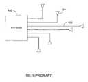
- FIG. 1illustrates a conventional RFID reader system for receiving signals from one or more RFID sensing tags that may be spatially distributed about an area.
- the RFID reader systemtypically includes an RFID reader 102 connected to a number of antennas 104 via cables 106 , through which power and data signals are transmitted.
- Such a configurationmay require many expensive cables 106 and antennas 104 , especially for interrogating a large number of widely-distributed RFID sensors.
- the antennas 104 within an RFID sensor system, or among systems,are tuned specifically for their environment and may add complexity to the system as a whole. Radio frequency transmissions are also usually limited to only a small number of specific carrier signal frequency bands, and the carrier signal is tightly controlled so as to not transmit sideband signals.
- This documentdiscloses an RFID sensor system and device for receiving signals from one or more spatially-distributed RFID sensing transceivers.
- These transceiversare a subcomponent of an RFID tag, and can include an RFID chip and non-tuned conductive substrate.
- An RFID sensor system having one or more spatially-distributed RFID sensing transceiversincludes first and second conductive paths, for receiving sensing signals from the one or more RFID sensing transceivers.
- the systemfurther includes a controller for providing a carrier signal on the first and second conductive paths, and for receiving the signals from the first and second conductive paths.
- an RFID sensor systemin another embodiment, includes a conducting path having first and second conductors, and one or more RFID sensing transceivers spatially-distributed along the conducting path and capactively-coupled to the first and second conductors.
- the systemfurther includes a controller coupled to the conducting path.
- the controllermay include an oscillator for providing an AC signal on the conducting path.
- radio frequency identification of a stimulusincludes perceiving the stimulus with at least one RFID sensing transceiver, generating a sensing signal based on the stimulus, capacitively coupling the sensing signal to a conductor, and transmitting the sensing signal on the conductor to a signal reader.
- a systemincludes multiple passive RFID transceivers, each including a sensor, conductors located in proximity to the passive RFID transceivers and allowing capacitance coupling between the conductors and the passive RFID transceivers, and a controller coupled with the conductors to effect the capacitance coupling, power the passive RFID transceivers, and receive obtained sensor data from the passive RFID transceivers.
- Each of the passive RFID transceiverscan be an RFID chip-attachment module and an integrated circuit (IC) chip comprising the sensor, and the conductors can be located in proximity to the RFID chip-attachment modules.
- the conductorscan be first and second conductive leads.
- An antennacan be coupled with one of the first and second conductive leads to allow RF transmissions with an external reader.
- the systems and techniques describedmay result in considerable system flexibility while also eliminating many of the costly components associated with a standard system.
- the systemcan greatly simplify and reduce the cost of an RFID sensor system.
- a traditional RFID readercan be replaced with a much less costly controller, and the system can be used in new applications that might otherwise be expensive or problematic.
- the RFID sensor system describedcan be used in monitoring various nodes on a printed circuit board or within a larger system, such as an automobile.
- the number of sensing transceivers that can be deployedmay be essentially unlimited.
- an enhancement of the system describedallows for external communication onto a common bus line using RF transmission through an antenna.
- one standard module independent of frequency and of the medium to which it is attachedcan be used.
- the cost of a standard modulecan be much less than the various RFID tags.
- Each module along with its sensorcan be pre-tested prior to attachment onto a system.
- the described systemcan utilize a carrier signal conducted on a hard wire, thus there need not be RF transmission, which are typically subject to many governmental regulations, compliance with which can increase system costs.
- Modulescan be added, or replaced, simply by placing the modules in close proximity to the conductors.
- the attachmentcan be easily accomplished, such as by using pressure sensitive adhesives.
- FIG. 1illustrates a conventional RFID tag reader system employing a network of antennas and transmission cables.
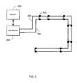
- FIG. 2is a block diagram of an RFID sensor system having one or more spatially-distributed RFID sensing transceivers.
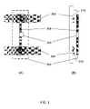
- FIG. 3(A)is a top-down view of a RFID sensing transceiver capacitively-coupled to a conducting path.
- FIG. 3(B)is a side view of a RFID sensing transceiver capacitively-coupled to a conducting path.
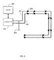
- FIG. 4is a block diagram of an RFID sensor system including an antenna coupled to the conducting path.
- the systems and techniques described hererelate to a distributed RF-coupled RFID system that uses significantly fewer components while offering greater flexibility than conventional RFID sensor systems.
- FIG. 2shows an RFID sensor system for receiving signals from one or more RFID sensing transceivers 200 that are spatially distributed about an area.
- the RFID sensing transceivers 200are adapted to provide a sensing signal in response to a detected stimulus, based on such stimuli as pressure, light, temperature, touch, chemical composition, biological composition, or changes thereof.
- the RFID sensing transceivers 200may be adapted to detect other types of stimuli or multiple types of stimuli.
- the RFID sensor systemincludes a first conductive path 202 and a second conductive path 204 .
- the first and second conductive paths 202 and 204can be capacitively coupled to the RFID sensing transceivers, but may also be directly coupled.
- the conductive paths 202 , 204may be made from copper or silver conductive paste attached to a substrate.
- Each conductive path 202 , 204conducts a carrier signal that both powers the RIFD sensing transceivers 200 and carries sensing signals received from the RFID sensing transceivers 200 via the capacitive-coupling.
- the first and second conductive paths 202 and 204each have a width of 1–10 mils, are substantially parallel to each other, and are spaced apart by 1–10 mils. Other dimensions and arrangements may be used.
- an RFID sensing transceiver 200can capacitively couple a sensing signal onto the conductive paths 202 and 204 for transmission by the carrier signal.
- the RFID sensor systemfurther includes a controller 206 that provides the carrier signal to the conductive paths 202 and 204 .
- the controller 206is also configured to receive the sensing signals from the first and second conductive paths 202 , 204 on the carrier signal.
- the controller 206may include an oscillator 210 for generating an AC signal that is used for the carrier signal. Other mechanisms for generating the carrier signal may also be employed.
- the carrier signalmay be a low frequency signal, such as 50–100 MHz, and thereby not require accurate or substantial control. However, higher or lower frequencies may be used for the carrier signals. Accordingly, those having skill in the art would recognize that the controller 206 and the carrier signal can be configured to operate in a wide range of frequencies. Using direct coupling, a DC signal can also be used.
- the RFID sensor systemfurther includes a reader 208 coupled to receive sensing signals from the RFID sensing transceivers 200 via the conductive paths 202 , 204 and the controller 206 .
- the reader 208is connected to the controller 206 .
- the reader 208includes logic 212 configured to receive the sensing signals and resolve an output based on the sensing signals.
- the logic 212may be embodied in hardware, software or firmware, or any combination thereof.
- the logic 212may include a microprocessor executing instructions for reading the sensing signals and resolving an output based on the sensing signals.
- the logic 212may be responsive and reconfigurable based on input signals from an input interface.
- the logic 212may include one or more logic circuits.
- the logic 212may be implemented in any number of ways, and therefore not limited to a particular logic mechanism or technique.
- the controller 206 and the reader 208may be integrated into a single device, which may be considered a controller of the RFID sensor system.
- FIGS. 3A and 3Bshow various views of an example RFID sensing transceiver 300 disposed with a first conductive path 302 and a second conductive path 304 .
- Each RFID sensing transceiver 300may include an RFID chip 306 coupled to a chip attachment module 308 .
- the chip attachment module 308serves to receive power signals from the first and second conductive paths 302 , 304 , as well as to supply a sensing signal based on a stimulus sensed by the RFID chip 306 .
- the chip 306can be attached to the chip attachment module 308 to form an RFID transceiver that can then be attached to a tuned antenna to form the FRID tag; the tuned module is then limited to a very narrow frequency range in which the system can operate.
- the RFID transceiver 300can be connected to conductive leads to form the distributed network described, and the frequency transmitted along the conductive leads can cover a wide range of frequencies.
- the chip attachment module 308can be shaped so as to form one conductor of a capacitive coupling 310 that couples the RFID sensing transceiver 300 to the first conductive path 302 and/or second conductive path 304 , allowing communication signals to cover a wide range of frequencies.
- the first and second conductive paths 302 and 304may be formed in a first substrate or layer, and the RFID sensing transceiver 300 may be formed in a second substrate or layer overlaid with the first substrate or layer.
- Various techniquesmay be used to form the first and second substrates or layers. The layers may be mated together from separate reels of the layers. Alternatively, the RFID sensing transceivers 300 may be mated individually to the conductive path layer.
- the substrate on which the conductors and/or RFID sensing transceivers are formedcan be made of a thin flexible substrate material such as polyethylene terephthalate (PET) (i.e. MylarTM) or other suitable material.
- PETpolyethylene terephthalate
- MylarTMpolyethylene terephthalate
- FIG. 4shows an alternative RFID sensing system, including an antenna 402 for receiving radio frequency signals from a remote or uncoupled RFID sensing transceiver, or other radio frequency signal source.
- the antenna 402may be connected to one of the conductive paths 202 or 204 . Accordingly, the connected conductive path 402 , controller 206 and reader 208 may receive sensing signals from multiple sources at various different frequencies or signal strengths.
Landscapes
- Engineering & Computer Science (AREA)
- Physics & Mathematics (AREA)
- Toxicology (AREA)
- Artificial Intelligence (AREA)
- Computer Vision & Pattern Recognition (AREA)
- General Physics & Mathematics (AREA)
- Theoretical Computer Science (AREA)
- Health & Medical Sciences (AREA)
- Computer Networks & Wireless Communication (AREA)
- Electromagnetism (AREA)
- General Health & Medical Sciences (AREA)
- Arrangements For Transmission Of Measured Signals (AREA)
- Coupling Device And Connection With Printed Circuit (AREA)
Abstract
Description
Claims (24)
Priority Applications (4)
| Application Number | Priority Date | Filing Date | Title |
|---|---|---|---|
| US10/676,226US7026936B2 (en) | 2003-09-30 | 2003-09-30 | Distributed RF coupled system |
| TW093109153ATWI249709B (en) | 2003-09-30 | 2004-04-02 | Distributed RF coupled system |
| PCT/US2004/032139WO2005034010A2 (en) | 2003-09-30 | 2004-09-30 | Distributed rf coupled system |
| JP2004287444AJP4837270B2 (en) | 2003-09-30 | 2004-09-30 | RFID sensor system and RFID detection method |
Applications Claiming Priority (1)
| Application Number | Priority Date | Filing Date | Title |
|---|---|---|---|
| US10/676,226US7026936B2 (en) | 2003-09-30 | 2003-09-30 | Distributed RF coupled system |
Publications (2)
| Publication Number | Publication Date |
|---|---|
| US20050068179A1 US20050068179A1 (en) | 2005-03-31 |
| US7026936B2true US7026936B2 (en) | 2006-04-11 |
Family
ID=34377337
Family Applications (1)
| Application Number | Title | Priority Date | Filing Date |
|---|---|---|---|
| US10/676,226Expired - LifetimeUS7026936B2 (en) | 2003-09-30 | 2003-09-30 | Distributed RF coupled system |
Country Status (4)
| Country | Link |
|---|---|
| US (1) | US7026936B2 (en) |
| JP (1) | JP4837270B2 (en) |
| TW (1) | TWI249709B (en) |
| WO (1) | WO2005034010A2 (en) |
Cited By (15)
| Publication number | Priority date | Publication date | Assignee | Title |
|---|---|---|---|---|
| US20080218352A1 (en)* | 2006-12-22 | 2008-09-11 | Fortium Technologies, Ltd. | Radio Frequency Identification |
| US8115635B2 (en) | 2005-02-08 | 2012-02-14 | Abbott Diabetes Care Inc. | RF tag on test strips, test strip vials and boxes |
| US20120126949A1 (en)* | 2006-10-31 | 2012-05-24 | Corning Incorporated | Radio Frequency Identification (RFID) Connected Tag Communications Protocol And Related Systems And Methods |
| US20120126950A1 (en)* | 2006-10-31 | 2012-05-24 | Corning Incorporated | Protocol For Communications Between A Radio Frequency Identification (RFID) Tag And A Connected Device, And Related Systems And Methods |
| US20120133490A1 (en)* | 2006-10-31 | 2012-05-31 | Corning Incorporated | Communications Between Multiple Radio Frequency Identification (RFID) Connected Tags And One Or More Devices, And Related Systems And Methods |
| US9563832B2 (en) | 2012-10-08 | 2017-02-07 | Corning Incorporated | Excess radio-frequency (RF) power storage and power sharing RF identification (RFID) tags, and related connection systems and methods |
| US10032102B2 (en) | 2006-10-31 | 2018-07-24 | Fiber Mountain, Inc. | Excess radio-frequency (RF) power storage in RF identification (RFID) tags, and related systems and methods |
| US10117043B2 (en) | 2014-09-22 | 2018-10-30 | Symbol Technologies, Llc | Serially-connected bluetooth low energy nodes |
| US11755874B2 (en) | 2021-03-03 | 2023-09-12 | Sensormatic Electronics, LLC | Methods and systems for heat applied sensor tag |
| US11769026B2 (en) | 2019-11-27 | 2023-09-26 | Sensormatic Electronics, LLC | Flexible water-resistant sensor tag |
| US11861440B2 (en) | 2019-09-18 | 2024-01-02 | Sensormatic Electronics, LLC | Systems and methods for providing tags adapted to be incorporated with or in items |
| US11869324B2 (en) | 2021-12-23 | 2024-01-09 | Sensormatic Electronics, LLC | Securing a security tag into an article |
| US11928538B2 (en) | 2019-09-18 | 2024-03-12 | Sensormatic Electronics, LLC | Systems and methods for laser tuning and attaching RFID tags to products |
| US12175849B2 (en) | 2018-05-22 | 2024-12-24 | Tyco Fire & Security Gmbh | Elongate flexible tag |
| US12223814B2 (en) | 2019-09-16 | 2025-02-11 | Sensormatic Electronics, LLC | Security tag for textiles using conductive thread |
Families Citing this family (91)
| Publication number | Priority date | Publication date | Assignee | Title |
|---|---|---|---|---|
| DE102004020593A1 (en)* | 2004-04-27 | 2005-11-24 | Infineon Technologies Ag | Fin field effect transistor arrangement and method for producing a fin field effect transistor arrangement |
| US7551081B2 (en) | 2004-11-10 | 2009-06-23 | Rockwell Automation Technologies, Inc. | Systems and methods that integrate radio frequency identification (RFID) technology with agent-based control systems |
| US7339476B2 (en) | 2004-11-10 | 2008-03-04 | Rockwell Automation Technologies, Inc. | Systems and methods that integrate radio frequency identification (RFID) technology with industrial controllers |
| US7477152B2 (en)* | 2005-03-14 | 2009-01-13 | Avery Dennison Corporation | RFID application test systems and methods |
| US7295117B2 (en)* | 2005-04-07 | 2007-11-13 | Avery Dennison | RFID device test thresholds systems and methods |
| US7411498B2 (en)* | 2005-04-07 | 2008-08-12 | Avery Dennison | RFID testing and classification systems and methods |
| US7298267B2 (en)* | 2005-05-09 | 2007-11-20 | Avery Dennison | RFID test interface systems and methods |
| US7298266B2 (en)* | 2005-05-09 | 2007-11-20 | Avery Dennison | RFID communication systems and methods |
| US7359823B2 (en)* | 2005-05-25 | 2008-04-15 | Avery Dennison | RFID device variable test systems and methods |
| US7388491B2 (en)* | 2005-07-20 | 2008-06-17 | Rockwell Automation Technologies, Inc. | Mobile RFID reader with integrated location awareness for material tracking and management |
| US7764191B2 (en) | 2005-07-26 | 2010-07-27 | Rockwell Automation Technologies, Inc. | RFID tag data affecting automation controller with internal database |
| US8260948B2 (en) | 2005-08-10 | 2012-09-04 | Rockwell Automation Technologies, Inc. | Enhanced controller utilizing RFID technology |
| US7510110B2 (en)* | 2005-09-08 | 2009-03-31 | Rockwell Automation Technologies, Inc. | RFID architecture in an industrial controller environment |
| US7931197B2 (en) | 2005-09-20 | 2011-04-26 | Rockwell Automation Technologies, Inc. | RFID-based product manufacturing and lifecycle management |
| US8025227B2 (en) | 2005-09-30 | 2011-09-27 | Rockwell Automation Technologies, Inc. | Access to distributed databases via pointer stored in RFID tag |
| US20070200712A1 (en)* | 2006-02-28 | 2007-08-30 | Symbol Technologies, Inc. | Smart RFID reader antennas |
| US7606530B1 (en) | 2006-03-11 | 2009-10-20 | Rockwell Collins, Inc. | RFID system for allowing access to remotely positioned RFID tags |
| US20070248358A1 (en)* | 2006-04-19 | 2007-10-25 | Michael Sauer | Electrical-optical cable for wireless systems |
| US20070285239A1 (en)* | 2006-06-12 | 2007-12-13 | Easton Martyn N | Centralized optical-fiber-based RFID systems and methods |
| US20070286599A1 (en)* | 2006-06-12 | 2007-12-13 | Michael Sauer | Centralized optical-fiber-based wireless picocellular systems and methods |
| US20070292136A1 (en) | 2006-06-16 | 2007-12-20 | Michael Sauer | Transponder for a radio-over-fiber optical fiber cable |
| US7627250B2 (en)* | 2006-08-16 | 2009-12-01 | Corning Cable Systems Llc | Radio-over-fiber transponder with a dual-band patch antenna system |
| US7787823B2 (en)* | 2006-09-15 | 2010-08-31 | Corning Cable Systems Llc | Radio-over-fiber (RoF) optical fiber cable system with transponder diversity and RoF wireless picocellular system using same |
| US7848654B2 (en)* | 2006-09-28 | 2010-12-07 | Corning Cable Systems Llc | Radio-over-fiber (RoF) wireless picocellular system with combined picocells |
| US7782202B2 (en) | 2006-10-31 | 2010-08-24 | Corning Cable Systems, Llc | Radio frequency identification of component connections |
| US8264366B2 (en)* | 2009-03-31 | 2012-09-11 | Corning Incorporated | Components, systems, and methods for associating sensor data with component location |
| US7772975B2 (en)* | 2006-10-31 | 2010-08-10 | Corning Cable Systems, Llc | System for mapping connections using RFID function |
| US8421626B2 (en)* | 2006-10-31 | 2013-04-16 | Corning Cable Systems, Llc | Radio frequency identification transponder for communicating condition of a component |
| US7667574B2 (en)* | 2006-12-14 | 2010-02-23 | Corning Cable Systems, Llc | Signal-processing systems and methods for RFID-tag signals |
| US7760094B1 (en)* | 2006-12-14 | 2010-07-20 | Corning Cable Systems Llc | RFID systems and methods for optical fiber network deployment and maintenance |
| US8264355B2 (en) | 2006-12-14 | 2012-09-11 | Corning Cable Systems Llc | RFID systems and methods for optical fiber network deployment and maintenance |
| US8873585B2 (en) | 2006-12-19 | 2014-10-28 | Corning Optical Communications Wireless Ltd | Distributed antenna system for MIMO technologies |
| US8111998B2 (en)* | 2007-02-06 | 2012-02-07 | Corning Cable Systems Llc | Transponder systems and methods for radio-over-fiber (RoF) wireless picocellular systems |
| US7547150B2 (en)* | 2007-03-09 | 2009-06-16 | Corning Cable Systems, Llc | Optically addressed RFID elements |
| US7965186B2 (en)* | 2007-03-09 | 2011-06-21 | Corning Cable Systems, Llc | Passive RFID elements having visual indicators |
| US20100054746A1 (en) | 2007-07-24 | 2010-03-04 | Eric Raymond Logan | Multi-port accumulator for radio-over-fiber (RoF) wireless picocellular systems |
| US7855697B2 (en) | 2007-08-13 | 2010-12-21 | Corning Cable Systems, Llc | Antenna systems for passive RFID tags |
| US8175459B2 (en) | 2007-10-12 | 2012-05-08 | Corning Cable Systems Llc | Hybrid wireless/wired RoF transponder and hybrid RoF communication system using same |
| US8644844B2 (en) | 2007-12-20 | 2014-02-04 | Corning Mobileaccess Ltd. | Extending outdoor location based services and applications into enclosed areas |
| US20090267771A1 (en)* | 2008-04-28 | 2009-10-29 | Sirit Technologies Inc. | Passively transferring radio frequency signals |
| US8248208B2 (en) | 2008-07-15 | 2012-08-21 | Corning Cable Systems, Llc. | RFID-based active labeling system for telecommunication systems |
| US8731405B2 (en) | 2008-08-28 | 2014-05-20 | Corning Cable Systems Llc | RFID-based systems and methods for collecting telecommunications network information |
| US9673904B2 (en) | 2009-02-03 | 2017-06-06 | Corning Optical Communications LLC | Optical fiber-based distributed antenna systems, components, and related methods for calibration thereof |
| CN102369678B (en) | 2009-02-03 | 2015-08-19 | 康宁光缆系统有限责任公司 | Optical fiber based distributed antenna systems, assemblies and related methods for calibrating optical fiber based distributed antenna systems, assemblies |
| CN102396171B (en) | 2009-02-03 | 2015-09-30 | 康宁光缆系统有限责任公司 | Based on the distributing antenna system of optical fiber, assembly and the correlation technique for monitoring and configure distributing antenna system based on optical fiber, assembly |
| US8548330B2 (en) | 2009-07-31 | 2013-10-01 | Corning Cable Systems Llc | Sectorization in distributed antenna systems, and related components and methods |
| US8280259B2 (en) | 2009-11-13 | 2012-10-02 | Corning Cable Systems Llc | Radio-over-fiber (RoF) system for protocol-independent wired and/or wireless communication |
| EP2507746B1 (en)* | 2009-11-30 | 2015-10-14 | Corning Incorporated | Rfid condition latching |
| US8275265B2 (en) | 2010-02-15 | 2012-09-25 | Corning Cable Systems Llc | Dynamic cell bonding (DCB) for radio-over-fiber (RoF)-based networks and communication systems and related methods |
| US20110268446A1 (en) | 2010-05-02 | 2011-11-03 | Cune William P | Providing digital data services in optical fiber-based distributed radio frequency (rf) communications systems, and related components and methods |
| US9525488B2 (en) | 2010-05-02 | 2016-12-20 | Corning Optical Communications LLC | Digital data services and/or power distribution in optical fiber-based distributed communications systems providing digital data and radio frequency (RF) communications services, and related components and methods |
| US8172468B2 (en) | 2010-05-06 | 2012-05-08 | Corning Incorporated | Radio frequency identification (RFID) in communication connections, including fiber optic components |
| WO2012024247A1 (en) | 2010-08-16 | 2012-02-23 | Corning Cable Systems Llc | Remote antenna clusters and related systems, components, and methods supporting digital data signal propagation between remote antenna units |
| US9252874B2 (en) | 2010-10-13 | 2016-02-02 | Ccs Technology, Inc | Power management for remote antenna units in distributed antenna systems |
| EP2678972B1 (en) | 2011-02-21 | 2018-09-05 | Corning Optical Communications LLC | Providing digital data services as electrical signals and radio-frequency (rf) communications over optical fiber in distributed communications systems, and related components and methods |
| WO2012148940A1 (en) | 2011-04-29 | 2012-11-01 | Corning Cable Systems Llc | Systems, methods, and devices for increasing radio frequency (rf) power in distributed antenna systems |
| WO2012148938A1 (en) | 2011-04-29 | 2012-11-01 | Corning Cable Systems Llc | Determining propagation delay of communications in distributed antenna systems, and related components, systems and methods |
| EP2832012A1 (en) | 2012-03-30 | 2015-02-04 | Corning Optical Communications LLC | Reducing location-dependent interference in distributed antenna systems operating in multiple-input, multiple-output (mimo) configuration, and related components, systems, and methods |
| WO2013162988A1 (en) | 2012-04-25 | 2013-10-31 | Corning Cable Systems Llc | Distributed antenna system architectures |
| US9165232B2 (en) | 2012-05-14 | 2015-10-20 | Corning Incorporated | Radio-frequency identification (RFID) tag-to-tag autoconnect discovery, and related methods, circuits, and systems |
| US9965607B2 (en) | 2012-06-29 | 2018-05-08 | Apple Inc. | Expedited biometric validation |
| WO2014024192A1 (en) | 2012-08-07 | 2014-02-13 | Corning Mobile Access Ltd. | Distribution of time-division multiplexed (tdm) management services in a distributed antenna system, and related components, systems, and methods |
| US9455784B2 (en) | 2012-10-31 | 2016-09-27 | Corning Optical Communications Wireless Ltd | Deployable wireless infrastructures and methods of deploying wireless infrastructures |
| CN105308876B (en) | 2012-11-29 | 2018-06-22 | 康宁光电通信有限责任公司 | Remote unit antennas in distributing antenna system combines |
| US9647758B2 (en) | 2012-11-30 | 2017-05-09 | Corning Optical Communications Wireless Ltd | Cabling connectivity monitoring and verification |
| CN105452951B (en) | 2013-06-12 | 2018-10-19 | 康宁光电通信无线公司 | Voltage type optical directional coupler |
| WO2014199380A1 (en) | 2013-06-12 | 2014-12-18 | Corning Optical Communications Wireless, Ltd. | Time-division duplexing (tdd) in distributed communications systems, including distributed antenna systems (dass) |
| US9247543B2 (en) | 2013-07-23 | 2016-01-26 | Corning Optical Communications Wireless Ltd | Monitoring non-supported wireless spectrum within coverage areas of distributed antenna systems (DASs) |
| US9661781B2 (en) | 2013-07-31 | 2017-05-23 | Corning Optical Communications Wireless Ltd | Remote units for distributed communication systems and related installation methods and apparatuses |
| US9928355B2 (en) | 2013-09-09 | 2018-03-27 | Apple Inc. | Background enrollment and authentication of a user |
| US20150071508A1 (en)* | 2013-09-09 | 2015-03-12 | Apple Inc. | Background Enrollment and Authentication of a User |
| US9385810B2 (en) | 2013-09-30 | 2016-07-05 | Corning Optical Communications Wireless Ltd | Connection mapping in distributed communication systems |
| US9178635B2 (en) | 2014-01-03 | 2015-11-03 | Corning Optical Communications Wireless Ltd | Separation of communication signal sub-bands in distributed antenna systems (DASs) to reduce interference |
| US9775123B2 (en) | 2014-03-28 | 2017-09-26 | Corning Optical Communications Wireless Ltd. | Individualized gain control of uplink paths in remote units in a distributed antenna system (DAS) based on individual remote unit contribution to combined uplink power |
| US10360823B2 (en) | 2014-05-29 | 2019-07-23 | Yupo Corporation | Label, method for producing label, method for using label, and adherend having label |
| US9357551B2 (en) | 2014-05-30 | 2016-05-31 | Corning Optical Communications Wireless Ltd | Systems and methods for simultaneous sampling of serial digital data streams from multiple analog-to-digital converters (ADCS), including in distributed antenna systems |
| US9525472B2 (en) | 2014-07-30 | 2016-12-20 | Corning Incorporated | Reducing location-dependent destructive interference in distributed antenna systems (DASS) operating in multiple-input, multiple-output (MIMO) configuration, and related components, systems, and methods |
| US9730228B2 (en) | 2014-08-29 | 2017-08-08 | Corning Optical Communications Wireless Ltd | Individualized gain control of remote uplink band paths in a remote unit in a distributed antenna system (DAS), based on combined uplink power level in the remote unit |
| US9602210B2 (en) | 2014-09-24 | 2017-03-21 | Corning Optical Communications Wireless Ltd | Flexible head-end chassis supporting automatic identification and interconnection of radio interface modules and optical interface modules in an optical fiber-based distributed antenna system (DAS) |
| US10659163B2 (en) | 2014-09-25 | 2020-05-19 | Corning Optical Communications LLC | Supporting analog remote antenna units (RAUs) in digital distributed antenna systems (DASs) using analog RAU digital adaptors |
| US9420542B2 (en) | 2014-09-25 | 2016-08-16 | Corning Optical Communications Wireless Ltd | System-wide uplink band gain control in a distributed antenna system (DAS), based on per band gain control of remote uplink paths in remote units |
| WO2016071902A1 (en) | 2014-11-03 | 2016-05-12 | Corning Optical Communications Wireless Ltd. | Multi-band monopole planar antennas configured to facilitate improved radio frequency (rf) isolation in multiple-input multiple-output (mimo) antenna arrangement |
| WO2016075696A1 (en) | 2014-11-13 | 2016-05-19 | Corning Optical Communications Wireless Ltd. | Analog distributed antenna systems (dass) supporting distribution of digital communications signals interfaced from a digital signal source and analog radio frequency (rf) communications signals |
| US9729267B2 (en) | 2014-12-11 | 2017-08-08 | Corning Optical Communications Wireless Ltd | Multiplexing two separate optical links with the same wavelength using asymmetric combining and splitting |
| WO2016098111A1 (en) | 2014-12-18 | 2016-06-23 | Corning Optical Communications Wireless Ltd. | Digital- analog interface modules (da!ms) for flexibly.distributing digital and/or analog communications signals in wide-area analog distributed antenna systems (dass) |
| WO2016098109A1 (en) | 2014-12-18 | 2016-06-23 | Corning Optical Communications Wireless Ltd. | Digital interface modules (dims) for flexibly distributing digital and/or analog communications signals in wide-area analog distributed antenna systems (dass) |
| US20160249365A1 (en) | 2015-02-19 | 2016-08-25 | Corning Optical Communications Wireless Ltd. | Offsetting unwanted downlink interference signals in an uplink path in a distributed antenna system (das) |
| US9681313B2 (en) | 2015-04-15 | 2017-06-13 | Corning Optical Communications Wireless Ltd | Optimizing remote antenna unit performance using an alternative data channel |
| US9948349B2 (en) | 2015-07-17 | 2018-04-17 | Corning Optical Communications Wireless Ltd | IOT automation and data collection system |
| US10560214B2 (en) | 2015-09-28 | 2020-02-11 | Corning Optical Communications LLC | Downlink and uplink communication path switching in a time-division duplex (TDD) distributed antenna system (DAS) |
| US10236924B2 (en) | 2016-03-31 | 2019-03-19 | Corning Optical Communications Wireless Ltd | Reducing out-of-channel noise in a wireless distribution system (WDS) |
Citations (7)
| Publication number | Priority date | Publication date | Assignee | Title |
|---|---|---|---|---|
| US4135181A (en)* | 1976-01-30 | 1979-01-16 | General Electric Company | Automatic remote meter reading and control system |
| US4287515A (en)* | 1979-04-27 | 1981-09-01 | Baker Industries, Inc. | Fire detection system with multiple output signals |
| US4394655A (en)* | 1981-03-13 | 1983-07-19 | Baker Industries, Inc. | Bidirectional, interactive fire detection system |
| US4742335A (en)* | 1986-06-18 | 1988-05-03 | Baker Industries, Inc. | Sequential and/or random polling system with virtually instantaneous response time |
| US6266052B1 (en)* | 1993-09-03 | 2001-07-24 | Display Edge Technology, Ltd. | Power and information distribution system for article display or storage areas and related method |
| US6456481B1 (en)* | 2001-05-31 | 2002-09-24 | Greatbatch-Sierra, Inc. | Integrated EMI filter-DC blocking capacitor |
| US6714133B2 (en)* | 1999-12-15 | 2004-03-30 | Koninklijke Philips Electronics N.V. | Short range communication system |
Family Cites Families (1)
| Publication number | Priority date | Publication date | Assignee | Title |
|---|---|---|---|---|
| JP3632544B2 (en)* | 2000-02-14 | 2005-03-23 | 株式会社デンソー | ID tag and logistics container with ID tag |
- 2003
- 2003-09-30USUS10/676,226patent/US7026936B2/ennot_activeExpired - Lifetime
- 2004
- 2004-04-02TWTW093109153Apatent/TWI249709B/ennot_activeIP Right Cessation
- 2004-09-30JPJP2004287444Apatent/JP4837270B2/ennot_activeExpired - Fee Related
- 2004-09-30WOPCT/US2004/032139patent/WO2005034010A2/enactiveApplication Filing
Patent Citations (7)
| Publication number | Priority date | Publication date | Assignee | Title |
|---|---|---|---|---|
| US4135181A (en)* | 1976-01-30 | 1979-01-16 | General Electric Company | Automatic remote meter reading and control system |
| US4287515A (en)* | 1979-04-27 | 1981-09-01 | Baker Industries, Inc. | Fire detection system with multiple output signals |
| US4394655A (en)* | 1981-03-13 | 1983-07-19 | Baker Industries, Inc. | Bidirectional, interactive fire detection system |
| US4742335A (en)* | 1986-06-18 | 1988-05-03 | Baker Industries, Inc. | Sequential and/or random polling system with virtually instantaneous response time |
| US6266052B1 (en)* | 1993-09-03 | 2001-07-24 | Display Edge Technology, Ltd. | Power and information distribution system for article display or storage areas and related method |
| US6714133B2 (en)* | 1999-12-15 | 2004-03-30 | Koninklijke Philips Electronics N.V. | Short range communication system |
| US6456481B1 (en)* | 2001-05-31 | 2002-09-24 | Greatbatch-Sierra, Inc. | Integrated EMI filter-DC blocking capacitor |
Cited By (22)
| Publication number | Priority date | Publication date | Assignee | Title |
|---|---|---|---|---|
| US8223021B2 (en) | 2005-02-08 | 2012-07-17 | Abbott Diabetes Care Inc. | RF tag on test strips, test strip vials and boxes |
| US8115635B2 (en) | 2005-02-08 | 2012-02-14 | Abbott Diabetes Care Inc. | RF tag on test strips, test strip vials and boxes |
| US8542122B2 (en) | 2005-02-08 | 2013-09-24 | Abbott Diabetes Care Inc. | Glucose measurement device and methods using RFID |
| US8390455B2 (en) | 2005-02-08 | 2013-03-05 | Abbott Diabetes Care Inc. | RF tag on test strips, test strip vials and boxes |
| US8358210B2 (en) | 2005-02-08 | 2013-01-22 | Abbott Diabetes Care Inc. | RF tag on test strips, test strip vials and boxes |
| US9652707B2 (en)* | 2006-10-31 | 2017-05-16 | Fiber Mountain, Inc. | Radio frequency identification (RFID) connected tag communications protocol and related systems and methods |
| US20120133490A1 (en)* | 2006-10-31 | 2012-05-31 | Corning Incorporated | Communications Between Multiple Radio Frequency Identification (RFID) Connected Tags And One Or More Devices, And Related Systems And Methods |
| US20120126950A1 (en)* | 2006-10-31 | 2012-05-24 | Corning Incorporated | Protocol For Communications Between A Radio Frequency Identification (RFID) Tag And A Connected Device, And Related Systems And Methods |
| US20120126949A1 (en)* | 2006-10-31 | 2012-05-24 | Corning Incorporated | Radio Frequency Identification (RFID) Connected Tag Communications Protocol And Related Systems And Methods |
| US9652708B2 (en)* | 2006-10-31 | 2017-05-16 | Fiber Mountain, Inc. | Protocol for communications between a radio frequency identification (RFID) tag and a connected device, and related systems and methods |
| US9652709B2 (en)* | 2006-10-31 | 2017-05-16 | Fiber Mountain, Inc. | Communications between multiple radio frequency identification (RFID) connected tags and one or more devices, and related systems and methods |
| US10032102B2 (en) | 2006-10-31 | 2018-07-24 | Fiber Mountain, Inc. | Excess radio-frequency (RF) power storage in RF identification (RFID) tags, and related systems and methods |
| US20080218352A1 (en)* | 2006-12-22 | 2008-09-11 | Fortium Technologies, Ltd. | Radio Frequency Identification |
| US9563832B2 (en) | 2012-10-08 | 2017-02-07 | Corning Incorporated | Excess radio-frequency (RF) power storage and power sharing RF identification (RFID) tags, and related connection systems and methods |
| US10117043B2 (en) | 2014-09-22 | 2018-10-30 | Symbol Technologies, Llc | Serially-connected bluetooth low energy nodes |
| US12175849B2 (en) | 2018-05-22 | 2024-12-24 | Tyco Fire & Security Gmbh | Elongate flexible tag |
| US12223814B2 (en) | 2019-09-16 | 2025-02-11 | Sensormatic Electronics, LLC | Security tag for textiles using conductive thread |
| US11861440B2 (en) | 2019-09-18 | 2024-01-02 | Sensormatic Electronics, LLC | Systems and methods for providing tags adapted to be incorporated with or in items |
| US11928538B2 (en) | 2019-09-18 | 2024-03-12 | Sensormatic Electronics, LLC | Systems and methods for laser tuning and attaching RFID tags to products |
| US11769026B2 (en) | 2019-11-27 | 2023-09-26 | Sensormatic Electronics, LLC | Flexible water-resistant sensor tag |
| US11755874B2 (en) | 2021-03-03 | 2023-09-12 | Sensormatic Electronics, LLC | Methods and systems for heat applied sensor tag |
| US11869324B2 (en) | 2021-12-23 | 2024-01-09 | Sensormatic Electronics, LLC | Securing a security tag into an article |
Also Published As
| Publication number | Publication date |
|---|---|
| TWI249709B (en) | 2006-02-21 |
| US20050068179A1 (en) | 2005-03-31 |
| TW200512656A (en) | 2005-04-01 |
| WO2005034010A2 (en) | 2005-04-14 |
| JP4837270B2 (en) | 2011-12-14 |
| JP2005108245A (en) | 2005-04-21 |
| WO2005034010A3 (en) | 2008-09-12 |
Similar Documents
| Publication | Publication Date | Title |
|---|---|---|
| US7026936B2 (en) | Distributed RF coupled system | |
| US7321290B2 (en) | Radio tag and system | |
| US7002474B2 (en) | Radio frequency identification (RFID) tag and a method of operating an RFID tag | |
| US6831561B2 (en) | Communications system and method with A/D converter | |
| KR20040098665A (en) | Integrated circuit with enhanced coupling | |
| US5729236A (en) | Identification system reader with multiplexed antennas | |
| US5606323A (en) | Diode modulator for radio frequency transponder | |
| US6498923B2 (en) | Telecommunication device | |
| US20100090805A1 (en) | Electronic device and management of competing contactless communication of such a device and a host equipment | |
| US20040257293A1 (en) | Circuit arrangement with simplified input circuit for phase modulation in a backscattering transponder | |
| EP1870841A1 (en) | Integrated circuit assembly including RFID and components thereof | |
| US9685496B2 (en) | Semiconductor device, method of manufacturing the same, and signal transmitting/receiving method using the semiconductor device | |
| US20090145971A1 (en) | Printed wireless rf identification label structure | |
| US20080129513A1 (en) | Method and apparatus for rfid tags | |
| EP2240890B1 (en) | Hybrid sensor/communication device and method | |
| US20210334615A1 (en) | Smart card | |
| US8680971B2 (en) | Wireless IC device and method of detecting environmental state using the device | |
| EP4411593A3 (en) | Electronic tag | |
| US7936268B2 (en) | Selectively coupling to feed points of an antenna system | |
| JP6229265B2 (en) | RFID tag system and temperature detection method | |
| JP2007213552A (en) | Control unit | |
| AU1005999A (en) | Non-contact IC card | |
| CN100354873C (en) | Electronic tag sensing system and method | |
| DE60330797D1 (en) | INTEGRATED RFID UHF SWITCHING | |
| CN109634148B (en) | Electronic equipment with radio frequency function |
Legal Events
| Date | Code | Title | Description |
|---|---|---|---|
| AS | Assignment | Owner name:BELLA ID SOLUTIONS, INC., CALIFORNIA Free format text:ASSIGNMENT OF ASSIGNORS INTEREST;ASSIGNOR:ROESNER, BRUCE B., PH.D.;REEL/FRAME:014569/0950 Effective date:20030930 | |
| AS | Assignment | Owner name:ID SOLUTIONS, INC., CAYMAN ISLANDS Free format text:ASSIGNMENT OF ASSIGNORS INTEREST;ASSIGNOR:BELLA ID SOLUTIONS, INC.;REEL/FRAME:016394/0763 Effective date:20050715 | |
| AS | Assignment | Owner name:ID SOLUTIONS, INC., TAIWAN Free format text:ASSIGNMENT OF ASSIGNORS INTEREST;ASSIGNOR:BELLA ID SOLUTIONS, INC.;REEL/FRAME:016807/0593 Effective date:20050715 | |
| STCF | Information on status: patent grant | Free format text:PATENTED CASE | |
| AS | Assignment | Owner name:NEOLOGY, INC., CALIFORNIA Free format text:JOINT ASSIGNMENT;ASSIGNOR:ID SOLUTIONS LLC;REEL/FRAME:019658/0185 Effective date:20070803 | |
| REMI | Maintenance fee reminder mailed | ||
| FPAY | Fee payment | Year of fee payment:4 | |
| SULP | Surcharge for late payment | ||
| AS | Assignment | Owner name:NEOLOGY, INC., CALIFORNIA Free format text:ASSIGNMENT OF ASSIGNORS INTEREST;ASSIGNOR:ID SOLUTIONS, INC.;REEL/FRAME:028569/0947 Effective date:20070803 | |
| FEPP | Fee payment procedure | Free format text:PAT HOLDER NO LONGER CLAIMS SMALL ENTITY STATUS, ENTITY STATUS SET TO UNDISCOUNTED (ORIGINAL EVENT CODE: STOL); ENTITY STATUS OF PATENT OWNER: LARGE ENTITY | |
| FPAY | Fee payment | Year of fee payment:8 | |
| MAFP | Maintenance fee payment | Free format text:PAYMENT OF MAINTENANCE FEE, 12TH YEAR, LARGE ENTITY (ORIGINAL EVENT CODE: M1553) Year of fee payment:12 | |
| AS | Assignment | Owner name:SMARTRAC TECHNOLOGY FLETCHER, INC., NORTH CAROLINA Free format text:ASSIGNMENT OF ASSIGNORS INTEREST;ASSIGNORS:NEOLOGY, INC.;SINGLE CHIP SYSTEMS CORP.;REEL/FRAME:046321/0793 Effective date:20180511 |