US7025769B1 - Surgical fixation system and related methods - Google Patents
Surgical fixation system and related methodsDownload PDFInfo
- Publication number
- US7025769B1 US7025769B1US10/455,113US45511303AUS7025769B1US 7025769 B1US7025769 B1US 7025769B1US 45511303 AUS45511303 AUS 45511303AUS 7025769 B1US7025769 B1US 7025769B1
- Authority
- US
- United States
- Prior art keywords
- retainer
- fastener
- surgical fixation
- receiving aperture
- plate
- Prior art date
- Legal status (The legal status is an assumption and is not a legal conclusion. Google has not performed a legal analysis and makes no representation as to the accuracy of the status listed.)
- Expired - Fee Related, expires
Links
- 238000000034methodMethods0.000titleclaimsdescription20
- 238000003780insertionMethods0.000claims4
- 230000037431insertionEffects0.000claims4
- 230000000399orthopedic effectEffects0.000abstractdescription6
- 230000007246mechanismEffects0.000abstractdescription3
- 230000008901benefitEffects0.000description3
- 210000003238esophagusAnatomy0.000description3
- 238000012986modificationMethods0.000description3
- 230000004048modificationEffects0.000description3
- 210000000988bone and boneAnatomy0.000description2
- 230000004927fusionEffects0.000description2
- 208000010392Bone FracturesDiseases0.000description1
- 239000000560biocompatible materialSubstances0.000description1
- 230000001010compromised effectEffects0.000description1
- 230000008878couplingEffects0.000description1
- 238000010168coupling processMethods0.000description1
- 238000005859coupling reactionMethods0.000description1
- 230000003247decreasing effectEffects0.000description1
- 230000006735deficitEffects0.000description1
- 230000000694effectsEffects0.000description1
- 239000007943implantSubstances0.000description1
- 210000004705lumbosacral regionAnatomy0.000description1
- 210000000056organAnatomy0.000description1
- 230000002093peripheral effectEffects0.000description1
- 238000007747platingMethods0.000description1
- 230000002265preventionEffects0.000description1
- 238000001356surgical procedureMethods0.000description1
- 210000000115thoracic cavityAnatomy0.000description1
Images


Classifications
- A—HUMAN NECESSITIES
- A61—MEDICAL OR VETERINARY SCIENCE; HYGIENE
- A61B—DIAGNOSIS; SURGERY; IDENTIFICATION
- A61B17/00—Surgical instruments, devices or methods
- A61B17/56—Surgical instruments or methods for treatment of bones or joints; Devices specially adapted therefor
- A61B17/58—Surgical instruments or methods for treatment of bones or joints; Devices specially adapted therefor for osteosynthesis, e.g. bone plates, screws or setting implements
- A61B17/68—Internal fixation devices, including fasteners and spinal fixators, even if a part thereof projects from the skin
- A61B17/80—Cortical plates, i.e. bone plates; Instruments for holding or positioning cortical plates, or for compressing bones attached to cortical plates
- A61B17/8033—Cortical plates, i.e. bone plates; Instruments for holding or positioning cortical plates, or for compressing bones attached to cortical plates having indirect contact with screw heads, or having contact with screw heads maintained with the aid of additional components, e.g. nuts, wedges or head covers
- A61B17/8042—Cortical plates, i.e. bone plates; Instruments for holding or positioning cortical plates, or for compressing bones attached to cortical plates having indirect contact with screw heads, or having contact with screw heads maintained with the aid of additional components, e.g. nuts, wedges or head covers the additional component being a cover over the screw head
- A—HUMAN NECESSITIES
- A61—MEDICAL OR VETERINARY SCIENCE; HYGIENE
- A61B—DIAGNOSIS; SURGERY; IDENTIFICATION
- A61B17/00—Surgical instruments, devices or methods
- A61B17/56—Surgical instruments or methods for treatment of bones or joints; Devices specially adapted therefor
- A61B17/58—Surgical instruments or methods for treatment of bones or joints; Devices specially adapted therefor for osteosynthesis, e.g. bone plates, screws or setting implements
- A61B17/68—Internal fixation devices, including fasteners and spinal fixators, even if a part thereof projects from the skin
- A61B17/70—Spinal positioners or stabilisers, e.g. stabilisers comprising fluid filler in an implant
- A61B17/7059—Cortical plates
Definitions
- the present inventionrelates generally to the area of surgical fixation, and more particularly to a surgical fixation system having an improved mechanism to prevent the back out of screws employed in securing a surgical fixation plate to an intended orthopedic location.
- One application where this is particularly worrisomeis with the use of a spinal fixation plate positioned over the anterior cervical spine. More specifically, such backing out may cause the screws to come into unwanted contact with the esophagus, which may lead to damage or impairment to that organ.
- Another problemis that, with the screws backed out (partially or fully), the mechanical properties of the overall construct will become compromised, which may lead to a loss in the height of the intervertebral space height and thereby cause pain to the patient.
- the present inventionis directed at overcoming, or at least reducing the effects of, one or more of the problems set forth above.
- the present inventionaccomplishes this goal by providing a surgical fixation system including a plate, at least one fastener, and a retainer.
- the platehas at least one fastener-receiving aperture and at least one retainer-receiving aperture.
- the fastener-receiving apertureextends between an upper surface and a lower surface of the plate.
- the retainer-receiving aperturehas a periphery defined by a plurality of tab members extending from the upper surface.
- the fastenerhas an anchor region and a head region.
- the anchor regionis dimensioned to be passed through the fastener-receiving aperture for introduction into a surgical target site, and the head region is dimensioned to be received at least partially within the fastener-receiving aperture.
- the retaineris dimensioned to be introduced into the retainer-receiving aperture to overlap at least a portion of the head region of the fastener and thereby prevent the fastener from backing out of the fastener-receiving aperture.
- the present inventionaccomplishes this goal by providing a method of surgical fixation including the steps of: (a) positioning a plate over an intended surgical target site, the plate having at least one fastener-receiving aperture and at least one retainer-receiving aperture, the fastener-receiving aperture extending between an upper surface and a lower surface of the plate, and the retainer-receiving aperture having a periphery defined by a plurality of tab members extending from the upper surface; (b) introducing a fastener into the fastener-receiving aperture such that an anchor region of said fastener is introduced into the surgical target site and a head region of the fastener is received at least partially within the fastener-receiving aperture; and (c) introducing a retainer into the retainer-receiving aperture to overlap at least a portion of the head region of the fastener and thereby prevent the fastener from backing out of the fastener-recei
- FIG. 1is a perspective view of a surgical fixation system according to a one aspect of the present invention
- FIG. 2is a top view of the surgical fixation system shown in FIG. 1 ;
- FIG. 3is a cross-sectional view of the surgical fixation system taken along lines 3 — 3 in FIG. 2 ;
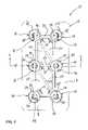
- FIG. 4is a perspective view of a surgical fixation system according to another broad aspect of the present invention.
- FIG. 5is a top view of the surgical fixation system shown in FIG. 4 ;
- FIG. 6is a cross-sectional view of the surgical fixation system taken along lines 6 — 6 in FIG. 5 ;
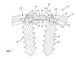
- FIG. 7is a cross-sectional view of the surgical fixation system shown in FIG. 6 with the tab member closed over at least a portion of the retainer according to a still further aspect of the present invention
- FIG. 8is a top view of a surgical fixation system according to another aspect of the present invention.
- FIG. 9is a top view of a surgical fixation system according to yet another aspect of the present invention.
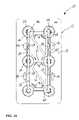
- FIG. 10is a top view of a surgical fixation system according to a still further aspect of the present invention.
- This inventionimproves upon the prior art by providing a surgical fixation system including a surgical fixation plate, a plurality of fasteners, and a retainer, wherein the retainer is configured and dimensioned to be received within a retainer-receiving aperture formed in the surgical fixation plate to prevent the fasteners from backing out over time.
- the retaineris capable of being easily introduced into the retainer-receiving aperture after the fasteners have been anchored into a given orthopedic target, which advantageously overcomes the drawbacks of the prior art. More specifically, back out prevention is accomplished in an easy to use and cost effective manner, in that simple off-the-shelf instrumentation may be used to deploy the retainer.
- the surgical fixation system of the present inventionmay be employed in any number of suitable orthopedic fixation procedures, including but not limited to lumbar spine fixation, thoracic spine fixation, as well as any non-spine fixation application such as bone fracture treatment.
- FIGS. 1–3illustrate a surgical fixation system 10 according to a first broad aspect of the present invention.
- the surgical fixation system 10comprises a surgical fixation plate 12 , a plurality of fasteners 14 , and a retainer 16 .
- the surgical fixation plate 12includes an upper surface 18 , a lower surface 20 , and an intermediate surface 22 .
- a plurality of fastener-receiving apertures 24is provided extending between the upper and lower surfaces 18 , 20 .
- a retainer-receiving aperture 26is provided having a periphery defined by a plurality of tab members 28 extending from said upper surface 18 .
- a groove 30is defined between each tab member 28 and a region of the intermediate surface 22 extending generally beneath the tab member 28 .
- the upper surface 18In use as an anterior cervical plating system, the upper surface 18 would be the anterior-most (facing the esophagus of the patient) and the lower surface 20 would be the posterior-most (in general abutment with the anterior portion of the cervical spine).
- the plate 12preferably has a curvature along both the upper and lower surfaces 18 , 20 .
- the upper surface 18has a generally reduced cross-sectional profile to avoid impinging upon or inadvertently contacting the esophagus of the patient, and the lower surface 20 can best accommodate the general curvature of the spine.
- FIG. 3the plate 12 preferably has a curvature along both the upper and lower surfaces 18 , 20 .
- the plate 12may be provided having any number of suitable outer peripheral shapes, including but not limited to areas of reduced width between the fastener-receiving apertures 24 .
- the plate 12may be provided in any number of suitable fashions and dimensions depending upon the particular surgical procedure.
- the plate 12may be (by way of example only) 2 mm thick between the upper surface 18 and lower surface 20 , wherein the tab member 28 is preferably 0.2 mm thick, the groove 30 is preferably 0.9 mm thick, and the thickness between the intermediate surface 22 and the lower surface 20 is approximately 0.9 mm.
- Each fastener 14includes a shaft 32 and a head 34 .
- the shaft 32is dimensioned and configured to be passed through a fastener-receiving aperture 24 and anchored (such as via threads 33 ) into a boney target (such as a vertebral body in the cervical spine).
- the head 34is dimensioned and configured to be received within the fastener-receiving aperture 24 .
- the concave curvature of the lower surface 20causes the shaft 32 of the fasteners 14 to angle medially, generally towards one another.
- the head 34 of the fastener 14may be equipped with any number of suitable mechanisms for engaging with a driving instrument, including but not limited to the hex-type female engagement portion 36 .
- fasteners 14Although shown with six fasteners 14 , it will be appreciated that the number of fasteners 14 (along with the number of fastener-receiving apertures 24 ) may be increased or decreased without departing from the scope of the invention.
- the fasteners 14may be constructed from any number of biocompatible materials, and provided in any number of dimensions (including length, diameter, thread pitch), such that they are suitable for use as a bone screw.
- the retainer 16is dimensioned and configured to be introduced into the retainer-receiving aperture 26 and overlap at least a portion of the head 34 of each fastener 14 such that the retainer 16 prevents unwanted back out of fasteners 14 from the plate 12 . In the embodiment shown, this is accomplished by providing the retainer 16 as a generally U-shaped member including a first elongate region 40 , a second elongate region 42 disposed generally parallel to said first region 40 , and a third elongate region 44 extending generally perpendicularly between the first and second regions 40 , 42 .
- the first and second regions 40 , 42are temporarily deformable relative to the third region 44 such that they may be forced towards one by applying force medially along a portion of the first and second regions 40 , 42 . This may be accomplished in any number of suitable fashions, including but not limited to engaging a tool (such as a pliers-type instrument) within loops 46 provided at the free ends of the first and second regions 40 , 42 and clamping together.
- a toolsuch as a pliers-type instrument
- the third region 44should be engaged at least partially under the tab member 28 at one end of the plate 12 such that the first and second regions 40 , 42 while in a contracted state (not shown) may be rotated about the third region 44 , introduced through the retainer-receiving aperture 26 , and thereafter released such that portions of the first and second regions 40 , 42 are disposed at least partially under the respective tab members 28 .
- each fastener head 34is covered by at least a portion of the retainer 16 to thereby prevent unwanted back out of fasteners 14 over time.
- the surgical fixation system 10may be provided having a variety of additional features and/or various modifications without departing from the scope of the invention.
- the surgical fixation system 10may be equipped with one or more viewing apertures 50 . This may be accomplished by removing portions of the plate 12 between the intermediate surface 22 and lower surface 20 , which may (by way of example only) result in one or more struts or cross bars 52 extending side to side (angularly or straight) across the plate 12 . In this fashion, the surgeon may visually inspect the surgical target site underneath portions of the plate 12 after placement on the spine.
- the viewing apertures 50may be provided in any number of suitable geometries, including but not limited to the generally triangular shapes shown best in FIG. 5 .
- the tab members 28may also be modified in any number of different fashions without departing from the scope of the present invention.
- the tab members 28may be deformed or otherwise moved such that the tab member 28 are brought to enclose a point or portions along the retainer 16 in an effort to prevent the retainer 16 from becoming dislodge or otherwise dissociated from the plate 12 .
- the tab members 28may be moved from a first position shown in FIG. 6 (extending generally medially from the upper surface 18 ) into a second position shown in FIG. 7 (extending generally downward toward the intermediate surface 22 to enclose some or all of the retainer 16 depending upon the width of the tab member 28 ).
- this manner of engagement(as well as others) may be employed to provide a hinged coupling arrangement between the third region 44 of the retainer 16 and the respective tab member 28 at one end of the plate 12 .
- the tab members 28may also be dimensioned in any number of suitable fashions without departing from the scope of the present invention.
- the tab members 28may extend a portion of the distance between adjacent fastener-receiving apertures 24 (as opposed to extending the entire distance as in the embodiment shown in FIGS. 1–7 ).
- the individual shapes of the various tab members 28may also be different, such as (by way of example only) providing one or more of the tab members 28 angled medially.
- the retainer-receiving aperture 26will be defined to include a flared region 54 towards one end of the plate 12 .
- the flared region 54is suitable to accommodate the medial deformation of at least one of the first and second regions 40 , 42 of the retainer 16 during introduction into the retainer-receiving aperture 26 .
- FIG. 10illustrates yet another manner of providing the tab members 28 according to a broad aspect of the present invention, wherein the tab members 28 are deformable in a generally medial direction to extend over at least a portion of the retainer 16 . In one embodiment, this is accomplished by providing tab-deployment apertures 56 (extending part or the entire distance between the upper surface 18 and the lower surface 20 ) immediately lateral to the tab members 28 .
- the tab members 28may thus be selectively deformed to move from a first—undeployed—position (shown in the two-deployment apertures 56 closest to the third region 44 of the retainer 16 ) to a second—deployed—position (shown in the two tab-deployment apertures 56 closest to the loops 46 of the retainer 16 ).
- Thismay be accomplished in any number of suitable fashions, including but not limited to placing an instrument (such as a flat screwdriver) into the tab-deployment aperture 56 of an undeployed tab member 28 and actuating the instrument (such as via rotation in the case of a screwdriver) to thereby force the tab member 28 into position above at least a portion of the retainer 16 .
Landscapes
- Health & Medical Sciences (AREA)
- Orthopedic Medicine & Surgery (AREA)
- Surgery (AREA)
- Life Sciences & Earth Sciences (AREA)
- Heart & Thoracic Surgery (AREA)
- Nuclear Medicine, Radiotherapy & Molecular Imaging (AREA)
- Engineering & Computer Science (AREA)
- Biomedical Technology (AREA)
- Neurology (AREA)
- Medical Informatics (AREA)
- Molecular Biology (AREA)
- Animal Behavior & Ethology (AREA)
- General Health & Medical Sciences (AREA)
- Public Health (AREA)
- Veterinary Medicine (AREA)
- Prostheses (AREA)
Abstract
Description
Claims (30)
Priority Applications (1)
| Application Number | Priority Date | Filing Date | Title |
|---|---|---|---|
| US10/455,113US7025769B1 (en) | 2002-06-04 | 2003-06-04 | Surgical fixation system and related methods |
Applications Claiming Priority (2)
| Application Number | Priority Date | Filing Date | Title |
|---|---|---|---|
| US38496602P | 2002-06-04 | 2002-06-04 | |
| US10/455,113US7025769B1 (en) | 2002-06-04 | 2003-06-04 | Surgical fixation system and related methods |
Publications (1)
| Publication Number | Publication Date |
|---|---|
| US7025769B1true US7025769B1 (en) | 2006-04-11 |
Family
ID=36127653
Family Applications (1)
| Application Number | Title | Priority Date | Filing Date |
|---|---|---|---|
| US10/455,113Expired - Fee RelatedUS7025769B1 (en) | 2002-06-04 | 2003-06-04 | Surgical fixation system and related methods |
Country Status (1)
| Country | Link |
|---|---|
| US (1) | US7025769B1 (en) |
Cited By (88)
| Publication number | Priority date | Publication date | Assignee | Title |
|---|---|---|---|---|
| US20050192577A1 (en)* | 2004-02-26 | 2005-09-01 | Pioneer Laboratories, Inc. | Bone plate system and methods |
| US20060142768A1 (en)* | 2001-12-14 | 2006-06-29 | Paul Kamaljit S | Bone treatment plate assembly |
| US20060217725A1 (en)* | 2005-03-11 | 2006-09-28 | Suh Sean S | Translational plate with spring beam retainer |
| US20060229620A1 (en)* | 2005-03-03 | 2006-10-12 | Accin Corporation | Method and apparatus for providing a retainer for a bone stabilization device |
| US20060235403A1 (en)* | 2005-03-17 | 2006-10-19 | Jason Blain | Flanged interbody fusion device with locking plate |
| US20060271052A1 (en)* | 2005-05-12 | 2006-11-30 | Stern Joseph D | Revisable anterior cervical plating system |
| US20070270880A1 (en)* | 2006-04-28 | 2007-11-22 | Lindemann Gary S | Bone screw revision tools and methods of use |
| US7306605B2 (en) | 2003-10-02 | 2007-12-11 | Zimmer Spine, Inc. | Anterior cervical plate |
| US20080033437A1 (en)* | 2003-04-25 | 2008-02-07 | Warsaw Orthopedic, Inc. | Non-Metallic Orthopedic Plate |
| US20080177263A1 (en)* | 2006-10-24 | 2008-07-24 | Aesculap Implant Systems, Inc | Dynamic stabilization device for anterior lower lumbar vertebral fusion |
| WO2008115981A1 (en)* | 2007-03-19 | 2008-09-25 | Alpinespine Llc | Active compression orthopedic plate system and method for using the same |
| US20080243135A1 (en)* | 2007-03-30 | 2008-10-02 | Robinson Randolph C | Driver-Fixator System, Method, and Apparatus |
| US20080249575A1 (en)* | 2007-04-03 | 2008-10-09 | Warsaw Orthopedic, Inc. | Anchor Member Locking Features |
| US20080249625A1 (en)* | 2007-04-03 | 2008-10-09 | Warsaw Orthopedic, Inc. | Composite Interbody Spacer |
| US20080249569A1 (en)* | 2007-04-03 | 2008-10-09 | Warsaw Orthopedic, Inc. | Implant Face Plates |
| WO2009042370A1 (en)* | 2007-09-28 | 2009-04-02 | Warsaw Orthopedic, Inc. | Surgical implant with an anti-backout feature |
| US20090105831A1 (en)* | 2007-10-19 | 2009-04-23 | Jones Robert J | Locking mechanisms and associated methods |
| US20090187218A1 (en)* | 2008-01-17 | 2009-07-23 | Amedica Corporation | Bone fixation plate with wire members for resisting back out of bone anchors |
| US20090326580A1 (en)* | 2008-06-25 | 2009-12-31 | Anderson Mark E | Spinal fixation device |
| US20100217393A1 (en)* | 2009-02-20 | 2010-08-26 | Theofilos Charles S | Interbody fusion system with intervertebral implant retention assembly |
| US20100249937A1 (en)* | 2009-03-27 | 2010-09-30 | Spinal Elements, Inc. | Flanged interbody fusion device |
| US20110054544A1 (en)* | 2009-08-31 | 2011-03-03 | Warsaw Orthopedic, Inc. | System with integral locking mechanism |
| US8070749B2 (en) | 2005-05-12 | 2011-12-06 | Stern Joseph D | Revisable anterior cervical plating system |
| US8088163B1 (en) | 2008-02-06 | 2012-01-03 | Kleiner Jeffrey B | Tools and methods for spinal fusion |
| US20120071933A1 (en)* | 2010-09-21 | 2012-03-22 | Warsaw Orothopedic, Inc. | Retaining mechanism |
| USD656610S1 (en) | 2009-02-06 | 2012-03-27 | Kleiner Jeffrey B | Spinal distraction instrument |
| WO2012040152A1 (en) | 2010-09-20 | 2012-03-29 | Jeffrey Kleiner | Fusion cage with combined biological delivery system |
| WO2012145048A1 (en) | 2011-04-20 | 2012-10-26 | Spinewindow Llc | Method and apparatus for performing retro peritoneal dissection |
| WO2012162600A2 (en) | 2011-05-26 | 2012-11-29 | Strauch Eric | Surgical drape with separable elements |
| US8366748B2 (en) | 2008-12-05 | 2013-02-05 | Kleiner Jeffrey | Apparatus and method of spinal implant and fusion |
| US20130053887A1 (en)* | 2011-08-26 | 2013-02-28 | Life Spine, Inc. | Bone Screw Retention in a Spinal Implant |
| US8685031B2 (en) | 2009-09-18 | 2014-04-01 | Spinal Surgical Strategies, Llc | Bone graft delivery system |
| US20140236241A1 (en)* | 2013-02-13 | 2014-08-21 | Thomas N. Scioscia | Variable angle bone plate with semi-constrained articulating screw |
| US8900277B2 (en) | 2004-02-26 | 2014-12-02 | Pioneer Surgical Technology, Inc. | Bone plate system |
| US8906028B2 (en) | 2009-09-18 | 2014-12-09 | Spinal Surgical Strategies, Llc | Bone graft delivery device and method of using the same |
| US8940030B1 (en) | 2011-01-28 | 2015-01-27 | Nuvasive, Inc. | Spinal fixation system and related methods |
| USD723682S1 (en) | 2013-05-03 | 2015-03-03 | Spinal Surgical Strategies, Llc | Bone graft delivery tool |
| US9011540B1 (en)* | 2005-03-24 | 2015-04-21 | Igip, Llc | Overlay or implant and method for improving stability of the implant |
| US9060877B2 (en) | 2009-09-18 | 2015-06-23 | Spinal Surgical Strategies, Llc | Fusion cage with combined biological delivery system |
| US9173694B2 (en) | 2009-09-18 | 2015-11-03 | Spinal Surgical Strategies, Llc | Fusion cage with combined biological delivery system |
| US9186193B2 (en) | 2009-09-18 | 2015-11-17 | Spinal Surgical Strategies, Llc | Fusion cage with combined biological delivery system |
| WO2015187397A1 (en) | 2013-06-07 | 2015-12-10 | George Frey | Patient-matched apparatus and methods for performing surgical procedures |
| US9247943B1 (en) | 2009-02-06 | 2016-02-02 | Kleiner Intellectual Property, Llc | Devices and methods for preparing an intervertebral workspace |
| USD750249S1 (en) | 2014-10-20 | 2016-02-23 | Spinal Surgical Strategies, Llc | Expandable fusion cage |
| US9451940B2 (en) | 2008-12-26 | 2016-09-27 | Pantheon Spinal, Llc | Method of retroperitoneal lateral insertion of spinal implants |
| US9629729B2 (en) | 2009-09-18 | 2017-04-25 | Spinal Surgical Strategies, Llc | Biological delivery system with adaptable fusion cage interface |
| US9717403B2 (en) | 2008-12-05 | 2017-08-01 | Jeffrey B. Kleiner | Method and apparatus for performing retro peritoneal dissection |
| USD797290S1 (en) | 2015-10-19 | 2017-09-12 | Spinal Surgical Strategies, Llc | Bone graft delivery tool |
| US9943341B2 (en) | 2013-07-16 | 2018-04-17 | K2M, Llc | Retention plate member for a spinal plate system |
| US9987024B2 (en) | 2010-06-29 | 2018-06-05 | Mighty Oak Medical, Inc. | Patient-matched apparatus and methods for performing surgical procedures |
| EP3357459A1 (en) | 2017-02-03 | 2018-08-08 | Spinal Surgical Strategies, LLC | Bone graft delivery device with positioning handle |
| US10245159B1 (en) | 2009-09-18 | 2019-04-02 | Spinal Surgical Strategies, Llc | Bone graft delivery system and method for using same |
| US10321833B2 (en) | 2016-10-05 | 2019-06-18 | Innovative Surgical Solutions. | Neural locating method |
| USD853560S1 (en) | 2008-10-09 | 2019-07-09 | Nuvasive, Inc. | Spinal implant insertion device |
| US10363108B2 (en) | 2010-06-07 | 2019-07-30 | Creative Surgical Solutions, Llc | Surgical drape with separable elements |
| US10376209B2 (en) | 2013-09-20 | 2019-08-13 | Innovative Surgical Solutions, Llc | Neural locating method |
| US10376208B2 (en) | 2013-09-20 | 2019-08-13 | Innovative Surgical Solutions, Llc | Nerve mapping system |
| USD857893S1 (en) | 2017-10-26 | 2019-08-27 | Mighty Oak Medical, Inc. | Cortical surgical guide |
| USD858765S1 (en) | 2017-10-26 | 2019-09-03 | Mighty Oak Medical, Inc. | Cortical surgical guide |
| US10449002B2 (en) | 2013-09-20 | 2019-10-22 | Innovative Surgical Solutions, Llc | Method of mapping a nerve |
| US10478096B2 (en) | 2013-08-13 | 2019-11-19 | Innovative Surgical Solutions. | Neural event detection |
| US10478097B2 (en) | 2013-08-13 | 2019-11-19 | Innovative Surgical Solutions | Neural event detection |
| US10653454B2 (en) | 2007-07-13 | 2020-05-19 | Mighty Oak Medical, Inc. | Spinal fixation systems |
| US10716553B2 (en) | 2017-04-19 | 2020-07-21 | Pantheon Spinal, Llc | Spine surgery retractor system and related methods |
| US10743890B2 (en) | 2016-08-11 | 2020-08-18 | Mighty Oak Medical, Inc. | Drill apparatus and surgical fixation devices and methods for using the same |
| US10758361B2 (en) | 2015-01-27 | 2020-09-01 | Spinal Elements, Inc. | Facet joint implant |
| USD895111S1 (en) | 2018-06-04 | 2020-09-01 | Mighty Oak Medical, Inc. | Sacro-iliac guide |
| US10870002B2 (en) | 2018-10-12 | 2020-12-22 | DePuy Synthes Products, Inc. | Neuromuscular sensing device with multi-sensor array |
| US10869616B2 (en) | 2018-06-01 | 2020-12-22 | DePuy Synthes Products, Inc. | Neural event detection |
| US10973656B2 (en) | 2009-09-18 | 2021-04-13 | Spinal Surgical Strategies, Inc. | Bone graft delivery system and method for using same |
| US11000321B2 (en) | 2017-05-25 | 2021-05-11 | Altus Partners Llc | Secondary screw blocking mechanism |
| US11039889B2 (en) | 2010-06-29 | 2021-06-22 | Mighty Oak Medical, Inc. | Patient-matched apparatus and methods for performing surgical procedures |
| US11185382B2 (en) | 2017-08-31 | 2021-11-30 | Creative Surgical Solutions, Llc | Separable sterile drape with z-shaped folds |
| USD948717S1 (en) | 2018-06-04 | 2022-04-12 | Mighty Oak Medical, Inc. | Sacro-iliac guide |
| US11376073B2 (en) | 2010-06-29 | 2022-07-05 | Mighty Oak Medical Inc. | Patient-matched apparatus and methods for performing surgical procedures |
| US11382769B2 (en) | 2018-09-20 | 2022-07-12 | Spinal Elements, Inc. | Spinal implant device |
| US11399777B2 (en) | 2019-09-27 | 2022-08-02 | DePuy Synthes Products, Inc. | Intraoperative neural monitoring system and method |
| US11633254B2 (en) | 2018-06-04 | 2023-04-25 | Mighty Oak Medical, Inc. | Patient-matched apparatus for use in augmented reality assisted surgical procedures and methods for using the same |
| US11666455B2 (en) | 2009-09-18 | 2023-06-06 | Spinal Surgical Strategies, Inc., A Nevada Corporation | Bone graft delivery devices, systems and kits |
| US11806197B2 (en) | 2010-06-29 | 2023-11-07 | Mighty Oak Medical, Inc. | Patient-matched apparatus for use in spine related surgical procedures and methods for using the same |
| US11813034B2 (en) | 2010-06-07 | 2023-11-14 | Creative Surgical Solutions, Llc | Surgical drape with separable elements |
| US11911284B2 (en) | 2020-11-19 | 2024-02-27 | Spinal Elements, Inc. | Curved expandable interbody devices and deployment tools |
| US12016573B2 (en) | 2016-08-11 | 2024-06-25 | Mighty Oak Medical, Inc. | Drill apparatus and surgical fixation devices and methods for using the same |
| US12279972B2 (en) | 2008-05-22 | 2025-04-22 | Spinal Surgical Strategies, Inc. | Spinal fusion cage system with inserter |
| US12279969B2 (en) | 2020-12-17 | 2025-04-22 | Spinal Elements, Inc. | Spinal implant device |
| US12357413B2 (en) | 2010-06-29 | 2025-07-15 | Mighty Oak Medical, Inc. | Patient-matched apparatus for use in spine related surgical procedures and methods for using the same |
| US12370006B2 (en) | 2020-10-04 | 2025-07-29 | Creative Surgical Solutions, Llc | Surgical drape with separable elements |
| US12440276B2 (en) | 2024-03-14 | 2025-10-14 | Mighty Oak Medical, Inc. | Systems and methods for presurgical planning |
Citations (6)
| Publication number | Priority date | Publication date | Assignee | Title |
|---|---|---|---|---|
| US6306139B1 (en)* | 1998-10-19 | 2001-10-23 | Scint'x | Intervertebral connection device with an anti-extraction device to prevent extraction of anchoring screws |
| US6458133B1 (en)* | 2000-12-19 | 2002-10-01 | Chih-I Lin | Spinal fixation and retrieval device |
| US6599290B2 (en)* | 2001-04-17 | 2003-07-29 | Ebi, L.P. | Anterior cervical plating system and associated method |
| US6652525B1 (en)* | 1998-04-30 | 2003-11-25 | Sofamor S.N.C. | Anterior implant for the spine |
| US6669700B1 (en)* | 1997-05-15 | 2003-12-30 | Sdgi Holdings, Inc. | Anterior cervical plating system |
| US6695846B2 (en)* | 2002-03-12 | 2004-02-24 | Spinal Innovations, Llc | Bone plate and screw retaining mechanism |
- 2003
- 2003-06-04USUS10/455,113patent/US7025769B1/ennot_activeExpired - Fee Related
Patent Citations (6)
| Publication number | Priority date | Publication date | Assignee | Title |
|---|---|---|---|---|
| US6669700B1 (en)* | 1997-05-15 | 2003-12-30 | Sdgi Holdings, Inc. | Anterior cervical plating system |
| US6652525B1 (en)* | 1998-04-30 | 2003-11-25 | Sofamor S.N.C. | Anterior implant for the spine |
| US6306139B1 (en)* | 1998-10-19 | 2001-10-23 | Scint'x | Intervertebral connection device with an anti-extraction device to prevent extraction of anchoring screws |
| US6458133B1 (en)* | 2000-12-19 | 2002-10-01 | Chih-I Lin | Spinal fixation and retrieval device |
| US6599290B2 (en)* | 2001-04-17 | 2003-07-29 | Ebi, L.P. | Anterior cervical plating system and associated method |
| US6695846B2 (en)* | 2002-03-12 | 2004-02-24 | Spinal Innovations, Llc | Bone plate and screw retaining mechanism |
Cited By (184)
| Publication number | Priority date | Publication date | Assignee | Title |
|---|---|---|---|---|
| US8128668B2 (en)* | 2001-12-14 | 2012-03-06 | Paul Kamaljit S | Bone treatment plate assembly |
| US20060142768A1 (en)* | 2001-12-14 | 2006-06-29 | Paul Kamaljit S | Bone treatment plate assembly |
| US20080033437A1 (en)* | 2003-04-25 | 2008-02-07 | Warsaw Orthopedic, Inc. | Non-Metallic Orthopedic Plate |
| US8617222B2 (en)* | 2003-04-25 | 2013-12-31 | Warsaw Orthopedic, Inc. | Non-metallic orthopedic plate |
| US7306605B2 (en) | 2003-10-02 | 2007-12-11 | Zimmer Spine, Inc. | Anterior cervical plate |
| US8470006B2 (en) | 2003-10-22 | 2013-06-25 | Kamaljit S. Paul | Bone repair systems |
| US7740649B2 (en) | 2004-02-26 | 2010-06-22 | Pioneer Surgical Technology, Inc. | Bone plate system and methods |
| US11129653B2 (en) | 2004-02-26 | 2021-09-28 | Pioneer Surgical Technology, Inc. | Bone plate system |
| US8900277B2 (en) | 2004-02-26 | 2014-12-02 | Pioneer Surgical Technology, Inc. | Bone plate system |
| US20050192577A1 (en)* | 2004-02-26 | 2005-09-01 | Pioneer Laboratories, Inc. | Bone plate system and methods |
| US7909859B2 (en) | 2004-02-26 | 2011-03-22 | Pioneer Surgical Technology, Inc. | Bone plate system and methods |
| US10166051B2 (en) | 2004-02-26 | 2019-01-01 | Pioneer Surgical Technology, Inc. | Bone plate system |
| US20060229620A1 (en)* | 2005-03-03 | 2006-10-12 | Accin Corporation | Method and apparatus for providing a retainer for a bone stabilization device |
| US20090171397A1 (en)* | 2005-03-03 | 2009-07-02 | Accelerated Innovation, Llc | Methods and apparatus for providing a retainer for a bone stabilization device |
| US8057522B2 (en) | 2005-03-03 | 2011-11-15 | Altus Partners, Llc | Methods and apparatus for providing a retainer for a bone stabilization device |
| US7481811B2 (en)* | 2005-03-11 | 2009-01-27 | Synthes (U.S.A.) | Translational plate with spring beam retainer |
| JP2008532627A (en)* | 2005-03-11 | 2008-08-21 | ジンテス ゲゼルシャフト ミット ベシュレンクテル ハフツング | Translation plate with spring beam holder |
| US20060217725A1 (en)* | 2005-03-11 | 2006-09-28 | Suh Sean S | Translational plate with spring beam retainer |
| US9265546B2 (en) | 2005-03-17 | 2016-02-23 | Spinal Elements, Inc. | Side-biased orthopedic fastener retention |
| US20060235403A1 (en)* | 2005-03-17 | 2006-10-19 | Jason Blain | Flanged interbody fusion device with locking plate |
| US9585707B2 (en) | 2005-03-17 | 2017-03-07 | Spinal Elements, Inc. | Flanged interbody fusion device with fastener insert and retaining ring |
| US8470039B2 (en) | 2005-03-17 | 2013-06-25 | Spinal Elements, Inc. | Flanged interbody fusion device with fastener insert and retaining ring |
| US8496691B2 (en) | 2005-03-17 | 2013-07-30 | Spinal Elements, Inc. | Side-biased orthopedic fastener retention |
| US8696721B2 (en) | 2005-03-17 | 2014-04-15 | Spinal Elements, Inc. | Orthopedic expansion fastener |
| US8496708B2 (en) | 2005-03-17 | 2013-07-30 | Spinal Elements, Inc. | Flanged interbody fusion device with hinge |
| US20060235533A1 (en)* | 2005-03-17 | 2006-10-19 | Jason Blain | Flanged interbody fusion device with hinge |
| US8100955B2 (en) | 2005-03-17 | 2012-01-24 | Spinal Elements, Inc. | Orthopedic expansion fastener |
| US20060235518A1 (en)* | 2005-03-17 | 2006-10-19 | Jason Blain | Flanged interbody fusion device with fastener insert and retaining ring |
| US20060235412A1 (en)* | 2005-03-17 | 2006-10-19 | Jason Blain | Side-biased orthopedic fastener retention |
| US20060235411A1 (en)* | 2005-03-17 | 2006-10-19 | Jason Blain | Orthopedic expansion fastener |
| US8801794B2 (en) | 2005-03-17 | 2014-08-12 | Spinal Elements, Inc. | Flanged interbody fusion device with fastener insert and retaining ring |
| US9936984B2 (en) | 2005-03-17 | 2018-04-10 | Spinal Elements, Inc. | Flanged interbody fusion device with fastener insert and retaining ring |
| US9011540B1 (en)* | 2005-03-24 | 2015-04-21 | Igip, Llc | Overlay or implant and method for improving stability of the implant |
| US9662146B2 (en) | 2005-05-12 | 2017-05-30 | Joseph D. Stern | Revisable anterior cervical plating system |
| US9095381B2 (en) | 2005-05-12 | 2015-08-04 | Joseph D. Stern | Revisable anterior cervical plating system |
| US20060271052A1 (en)* | 2005-05-12 | 2006-11-30 | Stern Joseph D | Revisable anterior cervical plating system |
| US8070749B2 (en) | 2005-05-12 | 2011-12-06 | Stern Joseph D | Revisable anterior cervical plating system |
| US8858556B2 (en) | 2005-05-12 | 2014-10-14 | Joseph D. Stern | Revisable anterior cervical plating system |
| US20090264886A1 (en)* | 2005-05-12 | 2009-10-22 | Stern Joseph D | Distraction device for use with a revisable anterior cervical plating system |
| US9668782B2 (en) | 2005-05-12 | 2017-06-06 | Joseph D. Stern | Revisable anterior cervical plating system |
| US8556895B2 (en) | 2005-05-12 | 2013-10-15 | Joseph D. Stern | Revisable anterior cervical plating system |
| US10383665B2 (en) | 2005-05-12 | 2019-08-20 | Globus Medical, Inc. | Revisable anterior cervical plating system |
| US20070270880A1 (en)* | 2006-04-28 | 2007-11-22 | Lindemann Gary S | Bone screw revision tools and methods of use |
| US8262710B2 (en) | 2006-10-24 | 2012-09-11 | Aesculap Implant Systems, Llc | Dynamic stabilization device for anterior lower lumbar vertebral fusion |
| US20080177263A1 (en)* | 2006-10-24 | 2008-07-24 | Aesculap Implant Systems, Inc | Dynamic stabilization device for anterior lower lumbar vertebral fusion |
| WO2008115981A1 (en)* | 2007-03-19 | 2008-09-25 | Alpinespine Llc | Active compression orthopedic plate system and method for using the same |
| US20080243135A1 (en)* | 2007-03-30 | 2008-10-02 | Robinson Randolph C | Driver-Fixator System, Method, and Apparatus |
| US20080249569A1 (en)* | 2007-04-03 | 2008-10-09 | Warsaw Orthopedic, Inc. | Implant Face Plates |
| US8268000B2 (en) | 2007-04-03 | 2012-09-18 | Warsaw Orthopedic, Inc. | Composite interbody spacer |
| US20080249575A1 (en)* | 2007-04-03 | 2008-10-09 | Warsaw Orthopedic, Inc. | Anchor Member Locking Features |
| US20080249625A1 (en)* | 2007-04-03 | 2008-10-09 | Warsaw Orthopedic, Inc. | Composite Interbody Spacer |
| US8425607B2 (en) | 2007-04-03 | 2013-04-23 | Warsaw Orthopedic, Inc. | Anchor member locking features |
| US10653454B2 (en) | 2007-07-13 | 2020-05-19 | Mighty Oak Medical, Inc. | Spinal fixation systems |
| JP2010540085A (en)* | 2007-09-28 | 2010-12-24 | ウォーソー・オーソペディック・インコーポレーテッド | Surgical implant with anti-retraction mechanism |
| US8613761B2 (en)* | 2007-09-28 | 2013-12-24 | Warsaw Orthopedic, Inc. | Surgical implant with an anti-backout feature |
| WO2009042370A1 (en)* | 2007-09-28 | 2009-04-02 | Warsaw Orthopedic, Inc. | Surgical implant with an anti-backout feature |
| US20090088808A1 (en)* | 2007-09-28 | 2009-04-02 | Warsaw Orthopedic, Inc, | Surgical implant with an anti-backout feature |
| CN101801296B (en)* | 2007-09-28 | 2012-07-18 | 华沙整形外科股份有限公司 | Surgical implant with an anti-backout feature |
| US20090105831A1 (en)* | 2007-10-19 | 2009-04-23 | Jones Robert J | Locking mechanisms and associated methods |
| US8882813B2 (en) | 2007-10-19 | 2014-11-11 | Spinesmith Partners, L.P. | Locking mechanisms and associated methods |
| US20090187218A1 (en)* | 2008-01-17 | 2009-07-23 | Amedica Corporation | Bone fixation plate with wire members for resisting back out of bone anchors |
| USD696399S1 (en) | 2008-02-06 | 2013-12-24 | Kleiner Intellectual Property, Llc | Spinal distraction instrument |
| US8715355B2 (en) | 2008-02-06 | 2014-05-06 | Nuvasive, Inc. | Spinal fusion cage with removable planar elements |
| US8808305B2 (en) | 2008-02-06 | 2014-08-19 | Jeffrey B. Kleiner | Spinal fusion cage system with inserter |
| US11129730B2 (en) | 2008-02-06 | 2021-09-28 | Spinal Surgical Strategies, Inc., a Nevada corpora | Spinal fusion cage system with inserter |
| US9439782B2 (en) | 2008-02-06 | 2016-09-13 | Jeffrey B. Kleiner | Spinal fusion cage system with inserter |
| US10179054B2 (en) | 2008-02-06 | 2019-01-15 | Jeffrey B. Kleiner | Spinal fusion cage system with inserter |
| USD700322S1 (en) | 2008-02-06 | 2014-02-25 | Jeffrey B. Kleiner | Intervertebral surgical tool |
| US8088163B1 (en) | 2008-02-06 | 2012-01-03 | Kleiner Jeffrey B | Tools and methods for spinal fusion |
| US8292960B2 (en) | 2008-02-06 | 2012-10-23 | Kleiner Intellectual Property, Llc | Spinal fusion cage with removable planar elements |
| US8277510B2 (en) | 2008-02-06 | 2012-10-02 | Kleiner Intellectual Property, Llc | Tools and methods for spinal fusion |
| US12279972B2 (en) | 2008-05-22 | 2025-04-22 | Spinal Surgical Strategies, Inc. | Spinal fusion cage system with inserter |
| US8425514B2 (en) | 2008-06-25 | 2013-04-23 | Westmark Medical, Llc. | Spinal fixation device |
| US20090326580A1 (en)* | 2008-06-25 | 2009-12-31 | Anderson Mark E | Spinal fixation device |
| USD853560S1 (en) | 2008-10-09 | 2019-07-09 | Nuvasive, Inc. | Spinal implant insertion device |
| US9717403B2 (en) | 2008-12-05 | 2017-08-01 | Jeffrey B. Kleiner | Method and apparatus for performing retro peritoneal dissection |
| US8870882B2 (en) | 2008-12-05 | 2014-10-28 | Jeffrey KLEINER | Apparatus and method of spinal implant and fusion |
| US10617293B2 (en) | 2008-12-05 | 2020-04-14 | Jeffrey B. Kleiner | Method and apparatus for performing retro peritoneal dissection |
| US8366748B2 (en) | 2008-12-05 | 2013-02-05 | Kleiner Jeffrey | Apparatus and method of spinal implant and fusion |
| US9427264B2 (en) | 2008-12-05 | 2016-08-30 | Jeffrey KLEINER | Apparatus and method of spinal implant and fusion |
| US9861496B2 (en) | 2008-12-05 | 2018-01-09 | Jeffrey B. Kleiner | Apparatus and method of spinal implant and fusion |
| US10959860B2 (en) | 2008-12-26 | 2021-03-30 | Pantheon Spinal, Llc | Method of retroperitoneal lateral insertion of spinal implants |
| US9451940B2 (en) | 2008-12-26 | 2016-09-27 | Pantheon Spinal, Llc | Method of retroperitoneal lateral insertion of spinal implants |
| US11969359B2 (en) | 2008-12-26 | 2024-04-30 | Pantheon Spinal, Llc | Method of retroperitoneal lateral insertion of spinal implants |
| US10085854B2 (en) | 2008-12-26 | 2018-10-02 | Pantheon Spinal, Llc | Method of retroperitoneal lateral insertion of spinal implants |
| US12383411B2 (en) | 2008-12-26 | 2025-08-12 | Pantheon Spinal, Llc | Spinal surgery methods and devices |
| US9247943B1 (en) | 2009-02-06 | 2016-02-02 | Kleiner Intellectual Property, Llc | Devices and methods for preparing an intervertebral workspace |
| USD656610S1 (en) | 2009-02-06 | 2012-03-27 | Kleiner Jeffrey B | Spinal distraction instrument |
| US10201355B2 (en) | 2009-02-06 | 2019-02-12 | Kleiner Intellectual Property, Llc | Angled surgical tool for removing tissue from within an intervertebral space |
| USD667542S1 (en) | 2009-02-06 | 2012-09-18 | Kleiner Jeffrey B | Spinal distraction instrument |
| US9826988B2 (en) | 2009-02-06 | 2017-11-28 | Kleiner Intellectual Property, Llc | Devices and methods for preparing an intervertebral workspace |
| US8187329B2 (en) | 2009-02-20 | 2012-05-29 | Spartan Cage Holding, Llc | Interbody fusion system with intervertebral implant retention assembly |
| US20100217393A1 (en)* | 2009-02-20 | 2010-08-26 | Theofilos Charles S | Interbody fusion system with intervertebral implant retention assembly |
| US8523947B2 (en) | 2009-02-20 | 2013-09-03 | Spartan Cage Holding, Llc | Interbody fusion system with intervertebral implant retention assembly |
| US10568664B2 (en) | 2009-03-27 | 2020-02-25 | Spinal Elements, Inc. | Flanged interbody fusion device |
| US20100249937A1 (en)* | 2009-03-27 | 2010-09-30 | Spinal Elements, Inc. | Flanged interbody fusion device |
| US9220547B2 (en) | 2009-03-27 | 2015-12-29 | Spinal Elements, Inc. | Flanged interbody fusion device |
| US11364057B2 (en) | 2009-03-27 | 2022-06-21 | Spinal Elements, Inc. | Flanged interbody fusion device |
| US20110054544A1 (en)* | 2009-08-31 | 2011-03-03 | Warsaw Orthopedic, Inc. | System with integral locking mechanism |
| US20110054543A1 (en)* | 2009-08-31 | 2011-03-03 | Warsaw Orthopedic, Inc. | Locking mechanism |
| US20110054542A1 (en)* | 2009-08-31 | 2011-03-03 | Warsaw Orthopedic, Inc. | System with integral locking mechanism |
| US8591555B2 (en) | 2009-08-31 | 2013-11-26 | Warsaw Orthopedic, Inc. | System with integral locking mechanism |
| US10195053B2 (en) | 2009-09-18 | 2019-02-05 | Spinal Surgical Strategies, Llc | Bone graft delivery system and method for using same |
| US12167971B2 (en) | 2009-09-18 | 2024-12-17 | Spinal Surgical Strategies, Inc. | Bone graft delivery devices, systems and kits |
| US8685031B2 (en) | 2009-09-18 | 2014-04-01 | Spinal Surgical Strategies, Llc | Bone graft delivery system |
| US9186193B2 (en) | 2009-09-18 | 2015-11-17 | Spinal Surgical Strategies, Llc | Fusion cage with combined biological delivery system |
| US11660208B2 (en) | 2009-09-18 | 2023-05-30 | Spinal Surgical Strategies, Inc. | Bone graft delivery system and method for using same |
| US9060877B2 (en) | 2009-09-18 | 2015-06-23 | Spinal Surgical Strategies, Llc | Fusion cage with combined biological delivery system |
| US9173694B2 (en) | 2009-09-18 | 2015-11-03 | Spinal Surgical Strategies, Llc | Fusion cage with combined biological delivery system |
| US9629729B2 (en) | 2009-09-18 | 2017-04-25 | Spinal Surgical Strategies, Llc | Biological delivery system with adaptable fusion cage interface |
| US12053393B2 (en) | 2009-09-18 | 2024-08-06 | Spinal Surgical Strategies, Inc. | Bone graft delivery system and method for use |
| US10245159B1 (en) | 2009-09-18 | 2019-04-02 | Spinal Surgical Strategies, Llc | Bone graft delivery system and method for using same |
| US11666455B2 (en) | 2009-09-18 | 2023-06-06 | Spinal Surgical Strategies, Inc., A Nevada Corporation | Bone graft delivery devices, systems and kits |
| US10973656B2 (en) | 2009-09-18 | 2021-04-13 | Spinal Surgical Strategies, Inc. | Bone graft delivery system and method for using same |
| US8709088B2 (en) | 2009-09-18 | 2014-04-29 | Spinal Surgical Strategies, Llc | Fusion cage with combined biological delivery system |
| US8906028B2 (en) | 2009-09-18 | 2014-12-09 | Spinal Surgical Strategies, Llc | Bone graft delivery device and method of using the same |
| US8864654B2 (en) | 2010-04-20 | 2014-10-21 | Jeffrey B. Kleiner | Method and apparatus for performing retro peritoneal dissection |
| US11185381B2 (en) | 2010-06-07 | 2021-11-30 | Creative Surgical Solutions, Llc | Surgical drape with separable elements |
| US10363110B2 (en) | 2010-06-07 | 2019-07-30 | Creative Surgical Solutions, Llc | Surgical drape with separable elements |
| US11813034B2 (en) | 2010-06-07 | 2023-11-14 | Creative Surgical Solutions, Llc | Surgical drape with separable elements |
| US8726907B2 (en) | 2010-06-07 | 2014-05-20 | Eric Strauch | Surgical drape with separable elements |
| US10363108B2 (en) | 2010-06-07 | 2019-07-30 | Creative Surgical Solutions, Llc | Surgical drape with separable elements |
| US11039889B2 (en) | 2010-06-29 | 2021-06-22 | Mighty Oak Medical, Inc. | Patient-matched apparatus and methods for performing surgical procedures |
| US12357413B2 (en) | 2010-06-29 | 2025-07-15 | Mighty Oak Medical, Inc. | Patient-matched apparatus for use in spine related surgical procedures and methods for using the same |
| US11376073B2 (en) | 2010-06-29 | 2022-07-05 | Mighty Oak Medical Inc. | Patient-matched apparatus and methods for performing surgical procedures |
| US11806197B2 (en) | 2010-06-29 | 2023-11-07 | Mighty Oak Medical, Inc. | Patient-matched apparatus for use in spine related surgical procedures and methods for using the same |
| US9987024B2 (en) | 2010-06-29 | 2018-06-05 | Mighty Oak Medical, Inc. | Patient-matched apparatus and methods for performing surgical procedures |
| WO2012040152A1 (en) | 2010-09-20 | 2012-03-29 | Jeffrey Kleiner | Fusion cage with combined biological delivery system |
| US20120071933A1 (en)* | 2010-09-21 | 2012-03-22 | Warsaw Orothopedic, Inc. | Retaining mechanism |
| US9504584B1 (en) | 2011-01-28 | 2016-11-29 | Nuvasive, Inc. | Spinal fusion implant and related methods |
| US8940030B1 (en) | 2011-01-28 | 2015-01-27 | Nuvasive, Inc. | Spinal fixation system and related methods |
| US9913730B1 (en) | 2011-01-28 | 2018-03-13 | Nuvasive, Inc. | Spinal fixation system and related methods |
| WO2012145048A1 (en) | 2011-04-20 | 2012-10-26 | Spinewindow Llc | Method and apparatus for performing retro peritoneal dissection |
| WO2012162600A2 (en) | 2011-05-26 | 2012-11-29 | Strauch Eric | Surgical drape with separable elements |
| US9351768B2 (en)* | 2011-08-26 | 2016-05-31 | Life Spine, Inc. | Bone screw retention in a spinal implant |
| US20130053887A1 (en)* | 2011-08-26 | 2013-02-28 | Life Spine, Inc. | Bone Screw Retention in a Spinal Implant |
| US9642652B2 (en)* | 2013-02-13 | 2017-05-09 | Choice Spine, Lp | Variable angle bone plate with semi-constrained articulating screw |
| US20140236241A1 (en)* | 2013-02-13 | 2014-08-21 | Thomas N. Scioscia | Variable angle bone plate with semi-constrained articulating screw |
| USD723682S1 (en) | 2013-05-03 | 2015-03-03 | Spinal Surgical Strategies, Llc | Bone graft delivery tool |
| EP3797716A1 (en) | 2013-06-07 | 2021-03-31 | Frey, George | Patient-matched apparatus |
| WO2015187397A1 (en) | 2013-06-07 | 2015-12-10 | George Frey | Patient-matched apparatus and methods for performing surgical procedures |
| US9943341B2 (en) | 2013-07-16 | 2018-04-17 | K2M, Llc | Retention plate member for a spinal plate system |
| US10478097B2 (en) | 2013-08-13 | 2019-11-19 | Innovative Surgical Solutions | Neural event detection |
| US10478096B2 (en) | 2013-08-13 | 2019-11-19 | Innovative Surgical Solutions. | Neural event detection |
| US10376209B2 (en) | 2013-09-20 | 2019-08-13 | Innovative Surgical Solutions, Llc | Neural locating method |
| US10376208B2 (en) | 2013-09-20 | 2019-08-13 | Innovative Surgical Solutions, Llc | Nerve mapping system |
| US10449002B2 (en) | 2013-09-20 | 2019-10-22 | Innovative Surgical Solutions, Llc | Method of mapping a nerve |
| USD750249S1 (en) | 2014-10-20 | 2016-02-23 | Spinal Surgical Strategies, Llc | Expandable fusion cage |
| US10758361B2 (en) | 2015-01-27 | 2020-09-01 | Spinal Elements, Inc. | Facet joint implant |
| USD797290S1 (en) | 2015-10-19 | 2017-09-12 | Spinal Surgical Strategies, Llc | Bone graft delivery tool |
| US10743890B2 (en) | 2016-08-11 | 2020-08-18 | Mighty Oak Medical, Inc. | Drill apparatus and surgical fixation devices and methods for using the same |
| USD895837S1 (en) | 2016-08-11 | 2020-09-08 | Mighty Oak Medical, Inc. | Surgical guide tray |
| US11925400B2 (en) | 2016-08-11 | 2024-03-12 | Mighty Oak Medical, Inc. | Fixation devices having fenestrations and methods for using the same |
| US10758283B2 (en) | 2016-08-11 | 2020-09-01 | Mighty Oak Medical, Inc. | Fixation devices having fenestrations and methods for using the same |
| US12016573B2 (en) | 2016-08-11 | 2024-06-25 | Mighty Oak Medical, Inc. | Drill apparatus and surgical fixation devices and methods for using the same |
| US11376049B2 (en) | 2016-08-11 | 2022-07-05 | Mighty Oak Medical Inc. | Fixation devices having fenestrations and methods for using the same |
| US12109042B2 (en) | 2016-10-05 | 2024-10-08 | Innovative Surgical Solutions, Llc | Neural locating system and method |
| US10321833B2 (en) | 2016-10-05 | 2019-06-18 | Innovative Surgical Solutions. | Neural locating method |
| US11311222B2 (en) | 2016-10-05 | 2022-04-26 | Innovative Surgical Solutions | Neural locating system |
| EP3357459A1 (en) | 2017-02-03 | 2018-08-08 | Spinal Surgical Strategies, LLC | Bone graft delivery device with positioning handle |
| US11478237B2 (en) | 2017-04-19 | 2022-10-25 | Pantheon Spinal, Llc | Spine surgery retractor system and related methods |
| US10716553B2 (en) | 2017-04-19 | 2020-07-21 | Pantheon Spinal, Llc | Spine surgery retractor system and related methods |
| US11963674B2 (en) | 2017-04-19 | 2024-04-23 | Pantheon Spinal, Llc | Spine surgery retractor system and related methods |
| US11000321B2 (en) | 2017-05-25 | 2021-05-11 | Altus Partners Llc | Secondary screw blocking mechanism |
| US11672623B2 (en) | 2017-08-31 | 2023-06-13 | Creative Surgical Solutions, Llc | Separable sterile drape with z-shaped folds |
| US11185382B2 (en) | 2017-08-31 | 2021-11-30 | Creative Surgical Solutions, Llc | Separable sterile drape with z-shaped folds |
| USD858765S1 (en) | 2017-10-26 | 2019-09-03 | Mighty Oak Medical, Inc. | Cortical surgical guide |
| USD857893S1 (en) | 2017-10-26 | 2019-08-27 | Mighty Oak Medical, Inc. | Cortical surgical guide |
| US10869616B2 (en) | 2018-06-01 | 2020-12-22 | DePuy Synthes Products, Inc. | Neural event detection |
| US11633254B2 (en) | 2018-06-04 | 2023-04-25 | Mighty Oak Medical, Inc. | Patient-matched apparatus for use in augmented reality assisted surgical procedures and methods for using the same |
| USD948717S1 (en) | 2018-06-04 | 2022-04-12 | Mighty Oak Medical, Inc. | Sacro-iliac guide |
| US12350111B2 (en) | 2018-06-04 | 2025-07-08 | Mighty Oak Medical, Inc. | Patient-matched apparatus for use in robotic assisted surgical procedures and methods for using the same |
| USD895111S1 (en) | 2018-06-04 | 2020-09-01 | Mighty Oak Medical, Inc. | Sacro-iliac guide |
| US12318311B2 (en) | 2018-09-20 | 2025-06-03 | Spinal Elements, Inc. | Spinal implant device |
| US11382769B2 (en) | 2018-09-20 | 2022-07-12 | Spinal Elements, Inc. | Spinal implant device |
| US12090320B2 (en) | 2018-10-12 | 2024-09-17 | DePuy Synthes Products, Inc. | Neuromuscular sensing device with multi-sensor array |
| US10870002B2 (en) | 2018-10-12 | 2020-12-22 | DePuy Synthes Products, Inc. | Neuromuscular sensing device with multi-sensor array |
| US12303301B2 (en) | 2019-09-27 | 2025-05-20 | DePuy Synthes Products, Inc. | Intraoperative neural monitoring system and method |
| US11399777B2 (en) | 2019-09-27 | 2022-08-02 | DePuy Synthes Products, Inc. | Intraoperative neural monitoring system and method |
| US12370006B2 (en) | 2020-10-04 | 2025-07-29 | Creative Surgical Solutions, Llc | Surgical drape with separable elements |
| US11911284B2 (en) | 2020-11-19 | 2024-02-27 | Spinal Elements, Inc. | Curved expandable interbody devices and deployment tools |
| US12414858B2 (en) | 2020-11-19 | 2025-09-16 | Spinal Elements, Inc. | Curved expandable interbody devices and deployment tools |
| US12279969B2 (en) | 2020-12-17 | 2025-04-22 | Spinal Elements, Inc. | Spinal implant device |
| US12440276B2 (en) | 2024-03-14 | 2025-10-14 | Mighty Oak Medical, Inc. | Systems and methods for presurgical planning |
Similar Documents
| Publication | Publication Date | Title |
|---|---|---|
| US7025769B1 (en) | Surgical fixation system and related methods | |
| US6945973B2 (en) | Slidable bone plate system | |
| JP2672082B2 (en) | Device for holding bone parts in a desired spatial relationship | |
| US5681310A (en) | Vertebral auxiliary fixation device having holding capability | |
| US9468534B2 (en) | Spinal implant with attachment system | |
| US6146384A (en) | Orthopedic fixation device and method of implantation | |
| US8328854B2 (en) | Cervical plate ratchet pedicle screws | |
| EP0934731B1 (en) | Bone fracture fixation devices | |
| KR101053428B1 (en) | Device including front plate for spinal column support | |
| US9204899B2 (en) | Segmental orthopedic device for spinal elongation and for treatment of scoliosis | |
| US7011659B2 (en) | Connector for attaching an alignment rod to a bone structure | |
| US8133263B2 (en) | Connector for attaching an alignment rod to a bone structure | |
| US6503250B2 (en) | Bone support assembly | |
| US6364883B1 (en) | Spinous process clamp for spinal fusion and method of operation | |
| US8298271B2 (en) | Instruments and methods for holding a bone plate | |
| US6613051B1 (en) | Anterior transpedicular fixation system and method for maintaining a vertebral column | |
| EP1444958A1 (en) | Spinal fixation system | |
| US20050010227A1 (en) | Bone support plate assembly | |
| IL147401A (en) | Vertebral osteosynthesis plate and osteosynthesis system | |
| US20060106387A1 (en) | Spinal plate system and method of use | |
| JP2003310633A (en) | Anterior bone plate system and method of use | |
| US20080234753A1 (en) | Spinal Stabilization Systems | |
| JP2006524114A (en) | Bone fixation plate device and method of using the same | |
| WO2002076317A1 (en) | Hinged anterior thoracic/lumbar plate | |
| US20140005723A1 (en) | Intra spinous process and method of bone graft placement |
Legal Events
| Date | Code | Title | Description |
|---|---|---|---|
| AS | Assignment | Owner name:NUVASIVE, INC., CALIFORNIA Free format text:CHANGE OF ADDRESS;ASSIGNOR:NUVASIVE, INC.;REEL/FRAME:022706/0920 Effective date:20080811 | |
| REMI | Maintenance fee reminder mailed | ||
| FEPP | Fee payment procedure | Free format text:PAT HOLDER NO LONGER CLAIMS SMALL ENTITY STATUS, ENTITY STATUS SET TO UNDISCOUNTED (ORIGINAL EVENT CODE: STOL); ENTITY STATUS OF PATENT OWNER: LARGE ENTITY | |
| REFU | Refund | Free format text:REFUND - SURCHARGE FOR LATE PAYMENT, SMALL ENTITY (ORIGINAL EVENT CODE: R2554); ENTITY STATUS OF PATENT OWNER: LARGE ENTITY Free format text:REFUND - SURCHARGE, PETITION TO ACCEPT PYMT AFTER EXP, UNINTENTIONAL (ORIGINAL EVENT CODE: R2551); ENTITY STATUS OF PATENT OWNER: LARGE ENTITY | |
| FPAY | Fee payment | Year of fee payment:4 | |
| SULP | Surcharge for late payment | ||
| REMI | Maintenance fee reminder mailed | ||
| LAPS | Lapse for failure to pay maintenance fees | ||
| STCH | Information on status: patent discontinuation | Free format text:PATENT EXPIRED DUE TO NONPAYMENT OF MAINTENANCE FEES UNDER 37 CFR 1.362 | |
| FP | Lapsed due to failure to pay maintenance fee | Effective date:20140411 | |
| AS | Assignment | Owner name:BANK OF AMERICA, N.A., AS ADMINISTRATIVE AGENT, NORTH CAROLINA Free format text:SECURITY INTEREST;ASSIGNORS:NUVASIVE, INC.;NUVASIVE CLINICAL SERVICES MONITORING, INC.;NUVASIVE CLINICAL SERVICES, INC.;AND OTHERS;REEL/FRAME:052918/0595 Effective date:20200224 |