US7025748B2 - Sheath based blood vessel puncture locator and depth indicator - Google Patents
Sheath based blood vessel puncture locator and depth indicatorDownload PDFInfo
- Publication number
- US7025748B2 US7025748B2US10/302,575US30257502AUS7025748B2US 7025748 B2US7025748 B2US 7025748B2US 30257502 AUS30257502 AUS 30257502AUS 7025748 B2US7025748 B2US 7025748B2
- Authority
- US
- United States
- Prior art keywords
- sheath
- blood vessel
- puncture site
- dilator
- marking
- Prior art date
- Legal status (The legal status is an assumption and is not a legal conclusion. Google has not performed a legal analysis and makes no representation as to the accuracy of the status listed.)
- Expired - Lifetime
Links
Images


Classifications
- A—HUMAN NECESSITIES
- A61—MEDICAL OR VETERINARY SCIENCE; HYGIENE
- A61B—DIAGNOSIS; SURGERY; IDENTIFICATION
- A61B17/00—Surgical instruments, devices or methods
- A61B17/0057—Implements for plugging an opening in the wall of a hollow or tubular organ, e.g. for sealing a vessel puncture or closing a cardiac septal defect
- A—HUMAN NECESSITIES
- A61—MEDICAL OR VETERINARY SCIENCE; HYGIENE
- A61B—DIAGNOSIS; SURGERY; IDENTIFICATION
- A61B17/00—Surgical instruments, devices or methods
- A61B17/00491—Surgical glue applicators
- A—HUMAN NECESSITIES
- A61—MEDICAL OR VETERINARY SCIENCE; HYGIENE
- A61B—DIAGNOSIS; SURGERY; IDENTIFICATION
- A61B17/00—Surgical instruments, devices or methods
- A61B17/0057—Implements for plugging an opening in the wall of a hollow or tubular organ, e.g. for sealing a vessel puncture or closing a cardiac septal defect
- A61B2017/00637—Implements for plugging an opening in the wall of a hollow or tubular organ, e.g. for sealing a vessel puncture or closing a cardiac septal defect for sealing trocar wounds through abdominal wall
- A—HUMAN NECESSITIES
- A61—MEDICAL OR VETERINARY SCIENCE; HYGIENE
- A61B—DIAGNOSIS; SURGERY; IDENTIFICATION
- A61B17/00—Surgical instruments, devices or methods
- A61B17/0057—Implements for plugging an opening in the wall of a hollow or tubular organ, e.g. for sealing a vessel puncture or closing a cardiac septal defect
- A61B2017/00646—Type of implements
- A61B2017/00654—Type of implements entirely comprised between the two sides of the opening
- A—HUMAN NECESSITIES
- A61—MEDICAL OR VETERINARY SCIENCE; HYGIENE
- A61B—DIAGNOSIS; SURGERY; IDENTIFICATION
- A61B17/00—Surgical instruments, devices or methods
- A61B17/0057—Implements for plugging an opening in the wall of a hollow or tubular organ, e.g. for sealing a vessel puncture or closing a cardiac septal defect
- A61B2017/00672—Locating means therefor, e.g. bleed back lumen
- A—HUMAN NECESSITIES
- A61—MEDICAL OR VETERINARY SCIENCE; HYGIENE
- A61B—DIAGNOSIS; SURGERY; IDENTIFICATION
- A61B90/00—Instruments, implements or accessories specially adapted for surgery or diagnosis and not covered by any of the groups A61B1/00 - A61B50/00, e.g. for luxation treatment or for protecting wound edges
- A61B90/06—Measuring instruments not otherwise provided for
- A61B2090/062—Measuring instruments not otherwise provided for penetration depth
Definitions
- the inventionrelates to delivering hemostasis promoting material to a blood vessel puncture site. More particularly, the invention relates to a sheath based blood vessel puncture locator and depth indicator to accurately deliver an absorbable sponge material to seal a blood vessel puncture site.
- a large number of diagnostic and interventional proceduralsinvolve the percutaneous introduction of instrumentation into a vein or artery.
- coronary angioplasty, angiography, atherectomy, stenting of arteries, and many other proceduresoften involve accessing the vasculature through a catheter placed in the femoral artery or other blood vessel. Once the procedure is completed and the catheter or other instrumentation is removed, bleeding from the punctured artery must be controlled.
- One class of such puncture sealing devicesfeatures an intraluminal anchor which is placed within the blood vessel and seals against an inside surface of the vessel puncture.
- the intraluminal plugmay be used in combination with a sealing material positioned on the outside of the blood vessel, such as collagen. Sealing devices of this type are disclosed in U.S. Pat. Nos. 4,852,568; 4,890,612; 5,021,059; and 5,061,274.
- an absorbable materialsuch as collagen or a non-absorbable tissue adhesive at the puncture site has several drawbacks including: 1) possible injection of the material into the blood vessel causing thrombosis; 2) a lack of pressure directly on the blood vessel puncture which may allow blood to escape beneath the material plug into the surrounding tissue; and 3) the inability to accurately place the absorbable material plug directly over the puncture site.
- an anchor and plug systemaddresses these problems to some extent but provides other problems including: 1) complex and difficult application; 2) partial occlusion of the blood vessel by the anchor when placed properly; and 3) complete blockage of the blood vessel or a branch of the blood vessel by the anchor if placed improperly.
- Another problem with the anchor and plug systeminvolves reaccess. Reaccess of a particular blood vessel site sealed with an anchor and plug system is not possible until the anchor has been completely absorbed because the anchor could be dislodged into the blood stream by an attempt to reaccess.
- the present inventiondiscloses a sheath based puncture locator and depth indicator.
- the present inventionprovides for locating a blood vessel puncture site and determining the depth of the puncture of the blood vessel extravascularly using the introducer sheath that is already in place within the tissue tract.
- the present inventionalso provide for positioning the introducer sheath extravascularly or outside the blood vessel, controlling the blood vessel puncture site, and delivering a hemostasis promoting material to a blood vessel puncture site.
- FIG. 1is an exploded side view of a first embodiment of a system for delivering hemostasis promoting material to a blood vessel puncture site by fluid pressure.
- FIG. 2is an assembled side view of the system of FIG. 1 .
- FIG. 3Ais a side cross sectional view of a portion of the system of FIG. 2 .
- FIG. 3Bis a side cross sectional view of a portion of FIG. 2 according to a first alternative embodiment with a flapper valve.
- FIG. 3Cis a side cross sectional view of a portion of FIG. 2 according to a second alternative embodiment in a first position.
- FIG. 3Dis a side cross sectional view of FIG. 3C in a second position.
- FIG. 3Eis a side view of a portion of the system of FIG. 2 according to a third alternative embodiment with a two position connecting system.
- FIG. 3Fis a side view of a portion of the system of FIG. 2 according to a fourth embodiment with an alternative two position connecting system.
- FIG. 3Gis a side cross sectional view of a portion of the system of FIG. 2 according to a fifth embodiment with another alternative two position connecting system.
- FIG. 4is an exploded side view of an alternative system for delivering hemostasis promoting material to a blood vessel puncture site by fluid pressure.
- FIG. 5is an assembled side view of the system of FIG. 4 .
- FIG. 6is a side cross sectional view of a portion of the system of FIG. 5 .
- FIG. 7is an exploded side view of another embodiment of a system for delivering hemostasis promoting material to a blood vessel puncture site by fluid pressure.
- FIG. 8is an assembled side view of the system of FIG. 7 .
- FIG. 9is a side cross sectional view of a portion of the assembled system of FIG. 7 .
- FIG. 10is an exploded side view of a further system for delivering hemostasis promoting material to a blood vessel puncture site by fluid pressure with the material delivered to a side branch of the sheath.
- FIG. 11is an assembled side view of the system of FIG. 10 .
- FIG. 12is a side cross sectional view of a portion of the system of FIG. 11 including a proximal end of the introducer sheath and control tip.
- FIG. 13is a side cross sectional view of a portion of the system of FIG. 11 including an exhaust valve, a hydration chamber, and a syringe.
- FIG. 14is a side cross sectional view of a portion of the system of FIG. 1 with a pledget of hemostasis promoting material positioned in the hydration chamber.
- FIG. 15is a side cross sectional view of a portion of the system of FIG. 1 with the sponge hydrated and advanced in preparation for delivery.
- FIG. 16is a side cross sectional view of a blood vessel puncture site with an introducer sheath and guidewire positioned in the blood vessel puncture.
- FIG. 17is a side cross sectional view of the blood vessel puncture site with the hemostasis promoting material delivery system connected to the introducer sheath and bleed back visible from the vent tube.
- FIG. 18is a side cross sectional view of the blood vessel puncture site with the hemostasis promoting material delivery system and introducer sheath withdrawn to a desired position for delivery of the hemostasis promoting material.
- FIG. 19is a side cross sectional view of the blood vessel puncture site with the hemostasis promoting material delivered to the blood vessel puncture site by fluid pressure.
- FIG. 20is a side cross sectional view of the blood vessel puncture site with the hemostasis promoting material delivery system and guidewire removed from the introducer sheath.
- FIG. 21is a side cross sectional view of the blood vessel puncture site with the introducer sheath withdrawn.
- FIG. 22is a view of the pledget handling system of one embodiment of the present invention.
- FIG. 23is enlarged view of a portion of the embodiment in FIG. 22 .
- FIG. 24is a sectional view of a portion of the device shown in FIG. 22 .
- FIG. 25is a schematic illustration of the operation of the device shown in FIG. 24 .
- FIG. 26is a sectional view of a portion of the device shown in FIG. 22 .
- FIG. 27is a schematic illustration of the operation of the device shown in FIG. 26 .
- FIG. 28is a sectional view of a portion of the device shown in FIG. 22 .
- FIG. 29is a schematic illustration of the operation of the device shown in FIG. 28 .
- FIG. 30is a view of an embodiment of the device shown in FIG. 28 in use with a conventional device.
- FIG. 31is a view of an embodiment of the device shown in FIG. 28 in use with a conventional device.
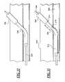
- FIG. 32is a side cross sectional view illustrating a blood vessel puncture site with an introducer sheath and guidewire positioned in the blood vessel puncture.
- FIG. 33is a side cross sectional view illustrating a sheath positioned extravascular the puncture of the blood vessel and a dilator to control the puncture site.
- FIG. 34is a side cross sectional view illustrating the determination of the depth of a puncture of the blood vessel with a sheath and dilator.
- FIG. 35is a side cross sectional view illustrating a sheath positioned extravascular the puncture of the blood vessel and a control tip dilator to control the puncture site.
- FIG. 36is a side cross sectional view illustrating a sheath positioned extravascular the puncture of the blood vessel to deliver a hemostasis promoting material or determine the depth of the puncture of the blood vessel.
- Embodiments of the present inventionare described herein in the context of a sheath based blood vessel puncture locator and depth indicator. Those of ordinary skill in the art will realize that the following detailed description of the present invention is illustrative only and is not intended to be in any way limiting. Other embodiments of the present invention will readily suggest themselves to such skilled persons having the benefit of this disclosure. Reference will now be made in detail to implementations of the present invention as illustrated in the accompanying drawings. The same reference indicators will be used throughout the drawings and the following detailed description to refer to the same or like parts.
- a system for delivering hemostasis promoting material of the present inventionallows the hemostasis promoting material to be delivered to a blood vessel puncture site by fluid pressure.
- the systemallows the hemostasis promoting material to be delivered through an introducer sheath which is already in place within a tissue tract.
- This systemincludes a control tip which is insertable through the introducer sheath to locate and occlude the blood vessel puncture site and a hydration chamber for receiving and delivering the hemostasis promoting material to the blood vessel puncture site.
- the present inventionis particularly designed for delivering a hemostasis promoting material in the form of an absorbable sponge through the introducer sheath by fluid pressure
- the systemmay also be used for delivering other hemostasis promoting materials which are useful for sealing a puncture site.
- the use of an absorbable hydrated sponge materialallows the delivery of more absorbable sponge material down through a smaller sheath by allowing the sponge material to be hydrated and compressed. Once delivered, the absorbable sponge rapidly expands to fill the entire width of the tissue tract and provides hemostasis at the puncture site.
- “pledget”means a piece of sponge formed into a generally elongated shape having a size which allows delivery in a hydrated state through a delivery cannula or introducer to a site of a puncture in a blood vessel.
- “Sponge”means a biocompatible material which is capable of being hydrated and is resiliently compressible in a hydrated state.
- the spongeis non-immunogenic and may be absorbable or non-absorbable.
- “Absorbable sponge”means sponge which, when implanted within a human or other mammalian body, is absorbed or resorbed by the body.
- “Hydrate”means to partially or fully saturate with a fluid, such as saline, water, contrast agent, thrombin, therapeutic agents, or the like.
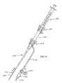
- the system of FIG. 1includes an introducer sheath 10 , a hydration chamber 12 with an attached control tip 14 , a coupler 16 , and a syringe 18 .
- the introducer sheath 10is an intravascular access sheath as is conventionally used for procedures such as coronary angioplasty and stenting procedures.
- the introducer sheath 10includes a proximal hub 22 connected to a tubular sheath 24 .
- a vent tube 26is in fluid communication with an interior of the hub 22 for purposes of providing a visual bleed back indication which will be discussed in further detail below.
- a vent cap 28is provided for opening and closing the vent tube 26 manually.
- FIGS. 3B–3Gother vent opening and closing mechanisms will be described in further detail below with respect to FIGS. 3B–3G .
- the hydration chamber 12is configured to receive a pledget of absorbable sponge material for hydration of the pledget and delivery of the pledget through the introducer sheath 10 .
- a proximal end of the hydration chamber 12includes a flange 36 or other connecting element for receiving the coupler 16 .
- a distal end 34 of the hydration chamber 12connects to the proximal hub 22 of the introducer sheath 12 .
- the control tip 14has an enlarged distal end 40 configured to be received in the puncture in the blood vessel and to control blood flow through the puncture in the blood vessel.
- the enlarged distal end 40is connected to a smaller diameter control tip tube 42 which extends from the enlarged distal end through the distal end of the hydration chamber 12 and out a side of the hydration chamber 12 to a proximal end 44 of the control tip.
- the enlarged distal end 40 of the control tipperforms the multiple functions of controlling blood flow through the blood vessel puncture, providing an indication of the position of the distal end of the introducer sheath, and guiding the hemostasis promoting material delivery system over a guidewire.
- the coupler 16allows the syringe 18 to be connected to the hydration chamber 12 . Removal of the coupler 16 from the hydration chamber 12 allows the pledget of absorbable sponge material to be easily inserted into the hydration chamber in its dry form. Upon connection of the coupler 16 to the hydration chamber 12 the conventional syringe 18 will be connected to the coupler 16 for injection of fluid into the hydration chamber.
- the coupler 16includes a seal 54 and two or more locking tabs 48 which lock over the flange 36 of the hydration chamber and are releasable by pressing on two wings 50 of the coupler.
- Stops 52 on the interior surfaces of the wings 50prevent the coupler 16 from being removed from the hydration chamber 12 when a syringe 18 is mounted on the coupler. It should be understood that many other coupler designs may also be used without departing from the present invention.
- FIGS. 1 , 2 , and 3 AIn use, the system of FIGS. 1 , 2 , and 3 A is assembled with a sponge placed inside the hydration chamber 12 and a syringe 18 containing water, saline solution, or other fluid attached to the hydration chamber by the coupler 16 .
- the spongeis hydrated and staged or moved, to a position at the distal end of the hydration chamber as will be described in further detail below.
- the syringe 18is preferable capable of generating a high pressure with a relatively low plunger force such as a 1 cc syringe.
- the introducer sheath 10is placed in the blood vessel puncture of a patient in a conventional manner for performance of the intravascular procedure. After the intravascular procedure, the introducer sheath 10 and a guidewire (not shown) are maintained in place extending into the blood vessel.
- the control tip 14is threaded over the proximal end of the guidewire and the hydration chamber 12 and control tip 14 are advanced into the introducer sheath until the hydration chamber distal end 34 is engaged with the hub 22 of the introducer sheath 10 . Bleed back is observed by a variety of methods which will be described below with respect to FIGS. 3A–3G .
- the vent cap 28is removed from the vent tube 26 to observe bleed back.
- the introducer sheath 10 , hydration chamber 12 , and control tip 14are withdrawn together slowly from the puncture site until the bleed back observed from the vent tube 26 stops.
- the bleed back stopswhen the enlarged distal end 40 of the control tip 44 is positioned in the blood vessel puncture preventing blood from escaping from the puncture.
- the distance d between the distal end of the tubular sheath 24 and the enlarged distal end 40 of the control tip 14is selected so that the point at which bleed back stops indicates that the distal end of the introducer sheath 10 is located at a desired delivery location for delivery of the hemostasis promoting material to the blood vessel puncture site.
- the distance dwill be selected to correspond to the size of the pledget to be delivered to the puncture site and will be selected such that the hemostasis promoting material is located in the tissue tract adjacent the blood vessel without extending into the lumen of the blood vessel.
- FIG. 3Aillustrates a first embodiment of a vent tube 26 with a vent cap 28 for observing bleed back.
- the vent tube 26has a relatively small diameter which is selected to provide a very noticeable spurt or stream of blood to indicate bleed back has occurred.
- the observance of bleed back from a larger tube such as the introducer sheathwould result in an oozing or dripping bleed back indication which is difficult for the user to use as a precise indicator of position.
- the vent tube 26has an inner diameter of about 0.4 mm to about 2 mm, preferably about 1 mm.
- FIG. 3Billustrates an alternative to manually placing the vent cap 28 into the vent tube 26 after bleed back has been used to locate the desired position for delivery of the hemostasis promoting material.
- a flapper valve 56is positioned over an inlet of the vent tube 26 inside the introducer hub 22 .
- the flapper valve 56responds to the sudden extreme pressures of delivering of the hemostasis promoting material and closes over the inlet to the vent tube 26 .
- Any of the known types of flapper valvesmay be used in the embodiment of FIG. 3B .
- FIG. 3Cillustrates a further alternative embodiment for opening and closing the vent tube 26 .
- FIG. 3Cillustrates a hydration chamber 12 A with an extended cylindrical distal end 60 . In the position illustrated in FIG. 3C , the inlet to the vent tube 26 is opened. Upon advancement of the hydration chamber 12 A with respect to the introducer sheath 10 by rotation of the hydration chamber the distal end 60 of the hydration chamber covers the inlet to the vent tube 26 , as shown in FIG. 3D .
- FIGS. 3E , 3 F, and 3 Gillustrate three further embodiments of a two position hydration chamber which may be advanced after bleed back is observed to cover the inlet to the vent tube 26 and prevent exhaust through the vent tube during delivery of the hemostasis promoting material.
- FIG. 3Eillustrates a modified coupler 16 A which can be connected to the hydration chamber 12 and is advanced to two different positions by locking on two sequential annular rings 64 provided on a introducer sheath 10 A.
- the two positions of the hydration chamber 12 with respect to the introducer sheath 10are provided by a coupler 16 B having two sets of locking tabs 66 for locking the coupler 16 in two locations on the introducer sheath 10 .
- FIG. 3Gillustrates an alternative embodiment of a sheath hub 70 having an inner locking annulus or flange 72 at a proximal end.
- a distal end 74 of a hydration chamber 76is provided with two locking grooves 78 which snap into the locking annulus 72 .
- the vent tube 26is opened.
- the hydration chamber 76is advanced further into the introducer sheath 70 the distal end 74 of the hydration chamber passes the vent tube 26 and prevents pressure loss.
- FIGS. 4–6illustrate an alternative embodiment of a system for delivering hemostasis promoting material to a blood vessel puncture site including another option for observing bleed back.
- FIG. 4illustrates an introducer sheath 110 , a hydration chamber 112 , a control tip 114 , a coupler 116 , and a syringe 118 .
- a vent tube 126extends from a side of a distal end of the hydration chamber 112 .
- the vent tube 126may be provided with a vent cap 128 for manually opening and closing the vent tube 126 .
- the vent tube closure system illustrated in FIG. 3Bmay be used. In the embodiment illustrated in FIGS.
- the introducer sheath 110may be any of those introducer sheaths which are currently used and may be connectable to the hydration chamber 112 by a lure lock connection as shown or by a coupler 16 or other coupling mechanisms as necessary.
- the hydration chamber 112includes a large inner diameter at a proximal end 132 and a small inner diameter distal end 134 .
- the vent tube 126is provided along the smaller inner diameter distal end 134 of the hydration chamber 112 distally of a tapered portion 136 of the hydration chamber.
- the hydrated spongeshould have a distal end which is positioned just proximally of the vent tube inlet so that the sponge does not block the inlet of the vent tube restricting the bleed back pathway.
- the system of FIGS. 4–6provides the advantage that the hydration chamber 112 and control tip 114 may be used with any of the known introducer sheaths 110 which may be in use in any particular intravascular procedure.
- FIGS. 7–9illustrate an alternative system for delivering hemostasis promoting material using a known introducer sheath 210 with an attached side port.
- FIG. 7illustrates the introducer sheath 210 , the hydration chamber 212 with the attached control tip 214 , a coupler 216 , and a syringe 218 .
- the hydration chamber 212may be connected to the introducer sheath 210 by a lure lock connection as described above or by an additional coupler 216 in the event that the introducer sheath 210 is not provided with a proximal lure connector.
- the introducer sheath 210 of FIG. 7includes a side port 220 which is used to view bleed back from the blood vessel puncture site. Connected to the side port 220 is a conventional stop cock valve 222 which is moveable between the open position illustrated in FIG. 7 and a closed position illustrated in phantom in FIG. 7 .
- a small diameter vent tube 226is preferable connected to one of the ports 224 of the side port 220 .
- the vent tube 226has a relatively small diameter and thus provides the desired blood spurt as a bleed back indicator.
- the vent tube 226may be connected to one of the ports 224 by any of the known connectors or may be provided integrally with the port.
- the stop cock 122is opened to observe bleed back passing through the introducer sheath and out the vent tube 226 .
- the introducer sheath 210 and hydration chamber 212are then withdrawn slowly until the bleed back is stopped by the presence of the enlarged distal end 240 of the control tip 214 in the blood vessel puncture. Once bleed back has stopped the stop cock 222 is closed to prevent fluid pressure loss from the introducer sheath 210 while the syringe plunger is depressed to advance the sponge through the introducer sheath 210 to the desired delivery location at the blood vessel puncture site.
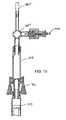
- FIGS. 10–13illustrate a further alternative embodiment of a system for delivering hemostasis promoting material in which a hydration chamber 312 is connected to a side port 320 of an introducer sheath 310 .
- the vent tube 326is connected to another port of the side port 320 .
- the stop cock 322is movable between an open delivery position shown in FIG. 10 and a closed bleed back position shown in phantom in FIG. 10 . In the closed bleed back position, bleed back is allowed through the vent tube 326 . In the open delivery position the hemostasis promoting material is delivered from the hydration chamber 312 to the introducer sheath.
- the hemostasis promoting materialwill pass from the hydration chamber 312 through the stop cock 322 and the side port 320 and into the introducer sheath 310 for delivery to the blood vessel puncture site.
- FIG. 12illustrates the connection of the control tip 314 to a proximal plug 330 which is connectable by a coupler 316 to the hub 332 of the introducer sheath 310 .
- the hemostasis promoting materialis delivered through the side port 320 of FIG. 12 and into the hub 332 of the introducer sheath 310 and then is delivered through the introducer sheath to the puncture site.
- FIGS. 14–21illustrate the preparation and use of the system for delivering hemostasis promoting material to a blood vessel puncture site.
- FIGS. 14–21illustrate the procedure which is used with the embodiment of FIGS. 1–3A , a similar procedure would be used with the other embodiments described above.
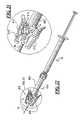
- FIGS. 14 and 15illustrate the hydration and staging of a pledget 20 of sponge material in the hydration chamber 12 . Once the pledget 20 is inserted into the hydration chamber 12 and the coupler 16 and syringe 18 have been connected to the proximal end of the hydration chamber, the pledget is ready to be hydrated and staged.
- a staging tube 100is used to position a distal end of the pledget 20 and prevent the pledget from being expelled from the hydration chamber 12 .
- the staging tube 100includes a tube 102 having a longitudinal slit (not shown) and preferable including a handle 104 .
- the staging tube 100uses a longitudinal slit to allow the staging tube to be mounted onto the shaft of the control tip 14 since the staging tube 100 will not fit over the enlarged distal end 40 of the control tip.
- saline or other fluidis injected at high pressure into the hydration chamber 12 by the syringe 18 to hydrate the pledget 20 .
- the staging tube 100is then moved to the position illustrated in FIG. 15 and additional fluid is injected by the syringe 18 to advance the pledget 20 into the distal end of the hydration chamber.
- the pledget 20should be staged with a distal end of the pledget positioned proximally of the inlet to the vent tube to prevent the pledget from blocking the bleed back vent.
- FIG. 16illustrates a blood vessel 106 with a puncture 108 and overlying tissue 109 .
- the introducer sheath 10 and a guidewire 30are in position in the blood vessel puncture 108 following an intravascular procedure.
- control tip 14has been inserted over the guidewire 30 and into the introducer sheath 10 and the distal end 34 of the hydration chamber 12 has been connected to the hub 22 of the introducer sheath.
- the vent cap 28is then removed from vent tube 26 and the spurt of blood B called bleed back is observed from the vent tube.
- the combination of the introducer sheath 10 , the hydration chamber 12 , and the control tip 14are slowly withdrawn from the puncture site until bleed back is no longer visible from the vent tube 26 .
- bleed backis no longer present this indicates that the enlarged distal end 40 of the control tip 14 is located in the blood vessel puncture 108 and is preventing blood from passing through the blood vessel puncture and into the introducer sheath 10 .
- FIG. 19illustrates a step of injecting the hemostasis promoting material or pledget 20 to the blood vessel puncture site by fluid pressure applied by the syringe 18 .
- the hemostasis promoting materialsubstantially fills the tissue tract at a space between the puncture in the blood vessel and the location of a distal end of the introducer sheath 10 .
- the pledget materialonce delivered, rapidly expands to fill the tissue tract and promotes hemostasis of the blood vessel puncture.
- the hydration chamber 12 , the control tip 14 , and the guidewire 30are then removed from the puncture site with the introducer sheath 10 held in place to stabilize the hemostasis promoting material 20 during removal of the remaining structures.
- the introducer sheath 10is then removed leaving the hemostasis promoting material in the tissue tract as shown in FIG. 21 .
- the hydration chamber 12 , control tip 14 , guidewire 30 , and introducer sheath 10may be withdrawn together from the puncture site.
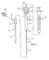
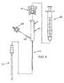
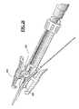
- FIGS. 22–31there is shown an alternative embodiment wherein a pledget handling system is substituted for the hydration chamber 12 shown and described above.
- FIG. 22shows the pledget handling system 400 with its proximal end coupled to the syringe 18 and the control tip extending from its distal end.
- the pledget handling system 400includes a pledget chamber 402 , a valve system 404 and a coupling system 406 .
- FIG. 23shows the valve system 404 and the coupling system 406 .
- the valve system 404includes a handle 410
- the coupling system 406includes two arms 412 , and the handle 410 and arms 412 can be manipulated by a user to control the operation of the device.
- a bleed back tube 414 and the proximal end of the control tip 44are also shown in this Figure.
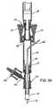
- FIG. 24shows a cross section view of the pledget handling system 400 , in which section lines have been omitted for the purpose of clarity.
- the pledget handling system 400includes cylindrical chamber 420 connected at its proximal end to a syringe-communication cannula 422 and at its distal end to a valve-entry port 424 .
- a cylindrical valve chamber 426which contains flow-control member 428 .
- the flow-control member 428is essentially a truncated cylinder in configuration, having part of its distal side (in the FIG. 24 orientation) missing and also having a semi-cylindrical vent port 430 formed in its upper surface.
- the flow-control member 428also has a semi-cylindrical cut-out portion 429 .
- the flow-control member 428is sized and shaped to be in close engagement with the valve chamber 426 so that when the flow-control member 428 is in the orientation shown in FIG. 24 fluid cannot flow from the valve-entry port 424 into the valve chamber 426 .
- the flow-control member 428is directly connected to the handle 410 (by a post, not shown) so that a user can rotate the flow-control member 428 by rotating the handle 410 .
- valve chamber 426At its distal end the valve chamber 426 is coupled to a valve-exit port 432 which is designed to receive introducer sheath 10 .
- the coupling system 406includes cylindrical cannula coupler 432 and the arms 412 are connected to the body of the coupling system by posts 434 which are made of a resilient material.
- FIG. 25there is a schematic illustration of the pledget handling system 400 in operation. It should be understood that the pledget 20 has been inserted into the chamber 420 , the syringe and the introducer sheath 10 have been connected to the pledget handling system 400 and the device is ready for the hydrating step.
- the userrotates the valve arm 412 so that the flow-control member 428 is in the orientation shown in FIG. 25 so that it prevents fluid flow from the valve-entry port 424 to valve exit port 432 .
- the usercan then hydrate the pledget by operating the syringe to introduce fluid into the chamber 420 .
- the usercan continue to the staging step, which is illustrated in FIGS. 26 and 27 .
- the userrotates the valve arm 412 so that the flow-control member 428 is in the orientation shown in FIGS. 26 and 27 .
- the flow-control member 428prevents fluid flow from flowing from the valve-entry port 424 to valve exit port 432 .
- the vent port 430is in communication with and allows a small amount of fluid to flow from the valve-entry port 424 .
- the vent port 430is also in fluid-flow communication with an exit port, not shown, which extends to the outside of the pledget handling system 400 , so that fluid can flow from the cut-out portion 429 to exit the pledget handling system 400 .
- the cut-out portionis small in size so that it permits fluid flow but does not allow for passage of the pledget.
- a bleed back channel 440is connected in fluid flow communication with the valve chamber 426
- a bleed back tube 442is connected in communication with the bleed back channel 440 .
- the coupling system 406includes two arms 412 , one coupled to each side of the pledget handling system 400 by posts 434 .
- Each arm 412has an engagement bracket 450 at its distal end.
- the postsare formed of resilient material so that the arms operate as levers with the posts 434 as fulcrums.
- the userapplies pressure with the fingers to the proximate portions of the arms 412 to force them toward one another which in turn forces the engagement brackets 450 away from each other. Then the user can locate the distal end of an introducer sheath 10 between the brackets 442 and release the proximal ends of the arms 412 so that the brackets then engage the sheath 10 .
- FIG. 30the coupling system is shown attached to a conventional sheath 452 made by the Terumo company. While in FIG. 31 the coupling system is shown attached to a conventional sheath 454 made by the Cordis company. It can be seen that the coupling system 406 is capable of being used with a variety of conventional sheaths.
- an alternative way of obtaining bleed backinvolves providing a hole in the control tip and bleed back through the internal lumen of the control tip.
- a bleed back holeis provided in the enlarged distal end 40 of the control tip 14 at a location close to the proximal end of the enlarged portion.
- the bleed back holecommunicates with the lumen of the control tip body and allows bleed back to be viewed at the proximal end 44 of the control tip which extends out of the side wall of the hydration chamber 12 .
- the distance d between the distal end of the introducer sheath and the enlarged distal end 40 of the control tip 14 in each of the foregoing embodimentsbe selected so that the point at which bleed back stops is the desired delivery location for delivering the hemostasis promoting material to the blood vessel puncture.
- the introducer sheath 10 , hydration chamber 12 , and control tip 14may be withdrawn an additional predetermined amount to the desired delivery location after bleed back stops.
- the transverse cross sectional profile of all of the foregoing structurescan be any desired shape, including square, oval, triangular, and preferable circular.
- the materials out of which the introducer sheaths, hydration chamber, control tip, and couplers are constructedare preferably selected to be relatively rigid and biocompatible, and more preferably are biocompatible polymers, biocompatible metals and metal alloys, and combinations thereof.
- the present inventionalso provides for positioning the introducer sheath in a desired extravascular location, controlling the blood vessel puncture site, and delivering a hemostasis promoting material to a blood vessel puncture site.
- the present inventionmay include a control tip dilator insertable through the introducer sheath to locate and seal the blood vessel puncture site by delivering a hemostasis promoting material to the puncture site.
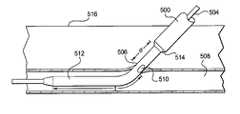
- FIG. 32is a side cross sectional view illustrating a blood vessel puncture site with an introducer sheath and guidewire positioned in the blood vessel puncture.
- the introducer sheath 500 and guidewire 504are positioned in the blood vessel puncture 506 following an intravascular procedure.
- the introducer sheath 500may be an intravascular access sheath as is conventionally used for procedures such as coronary angioplasty and stenting procedures.
- the coupling system 406includes two arms 412 , one coupled to each side of the pledget handling system 400 by posts 434 .
- Each arm 412has an engagement bracket 450 at its distal end.
- the postsare formed of resilient material so that the arms operate as levers with the posts 434 as fulcrums.
- the userapplies pressure with the fingers to the proximate portions of the arms 412 to force them toward one another which in turn forces the engagement brackets 450 away from each other. Then the user can locate the distal end of an introducer sheath 10 between the brackets 450 and release the proximal ends of the arms 412 so that the brackets then engage the sheath 10 .
- the coupling systemis shown attached to a conventional sheath 452 made by the Terumo company.
- FIG. 31the coupling system is shown attached to a conventional sheath 454 made by the Cordis company. It can be seen that the coupling system 406 is capable of being used with a variety of conventional sheaths.
- FIG. 34is a side cross sectional view illustrating the determination of the depth of a puncture of the blood vessel with a sheath and a dilator.
- the depth of the puncturemay be measured with external digital puncture control 520 as shown in FIG. 34 or without as shown in FIG. 35 .
- the sheathmay first be positioned as shown in FIG. 33 .
- a usermay then apply digital pressure 520 over the puncture 506 as is traditional during device exchanges.
- the sheath 500may then be grasped 518 at the skin surface 516 and withdrawn until the bleed back hole 510 exits the skin 516 .
- the depth of the puncture 506may be determined by distance S c , if external digital pressure is applied, or S u (shown in FIG.
- S c and S uis the distance between the bleed back hole 510 and the point where the sheath 500 was grasped 518 at the skin surface. Since S c is the depth of the blood vessel in a compressed state and S u is the depth of the blood vessel in an uncompressed state, it is important to note that S c will be less than S u due to the compression of the tissue above the blood vessel. Knowing the depth of the puncture may be important in determining how deep to place other devices such as extravascular depth markers or extravascular delivery systems.
- a markerwhich may be an axially movable member such as an o-ring, may be placed at the skin surface around the sheath 500 .
- depth indicator markersmay be pre-marked on the sheath 500 to locate the depth and location of the puncture.
- Depth indicator markersmay also be placed on the dilator 512 if the distal extension t is greater than the depth of the puncture.
- the distal extension tbe greater than or equal to S u or S c to provide control of the blood flow of the puncture 506 during and after the determination of the depth and location of the puncture 506 .
- FIG. 35is a side cross sectional view illustrating a sheath positioned extravascular the puncture of the blood vessel using a control tip dilator to control the puncture site.
- the control tip dilator 524may have an enlarged distal end 526 configured to be received in the puncture in the blood vessel and to control blood flow through the puncture in the blood vessel.
- the control tip dilator 524has a distal extension t and a proximal transition extension d 2 , the distance between the distal end of the sheath 514 and the lumen of the blood vessel 508 .
- the enlarged distal end 526is connected to a smaller diameter control tip tube 528 that extends proximally from the enlarged distal end 526 .
- the enlarged distal end 526 of the control tip 524performs the multiple functions of controlling blood flow through the blood vessel puncture and providing an indication of the position of the distal end of the introducer sheath 514 .
- the sheath 500may be used to provide bleed back indication to the user.
- the sheath 500may be withdrawn until blood stops entering the distal end 514 of the sheath 500 and the proximal transition end 528 of the control tip dilator controls the blood flow through the puncture 506 .
- the sheath 500is then located extravascular or outside the blood vessel.
- the location of the blood vessel puncture 506 relative to the distal end of the sheath 514is now known.
- removal of the control tip dilatorallows for ease of delivery of hemostasis promoting materials to seal the puncture site 506 since the sheath 500 is in the proper location for delivery of the hemostasis promoting material.
- external digital pressure as described above with reference to FIG. 34may be applied prior to removal of the control tip dilator.
- the control tip dilatormay then be removed and the hemostasis promoting material delivered through the sheath while the site is controlled by external digital pressure. After delivery of hemostasis promoting material, external pressure may be released.
- the control tip dilator 524may also be used to locate the depth of the puncture 506 with external digital pressure or without external digital pressure as was described above using the dilator.
- a usermay apply digital pressure over the puncture as is traditional during device exchanges.
- the sheath and control tip dilatorare grasped at the skin surface and withdrawn until the proximal transition end 528 of the control tip dilator exits the skin.
- the depth of the punctureeither S c or S u , can then be determined, S c and S u now being the distance between the proximal transition end of the control tip dilator and where the sheath was grasped or marked at the skin surface.
- a markermay be placed at the skin surface around the sheath, or depth indicator markers may be pre-marked on the sheath or control tip dilator to locate the depth and location of the puncture.
- FIG. 36is a side cross sectional view illustrating a sheath positioned extravascular the puncture of the blood vessel.
- the sheath 500 and guidewire 504are positioned intravascular the blood vessel as shown in FIG. 1 .
- bloodflows from the blood vessel, enters the distal end 514 of the sheath and exits the proximal end 526 of the sheath 500 .
- the depth or location of the puncture 506 of the blood vesselmay be located by applying external digital pressure 522 directly over the puncture 506 .
- the sheath 500may be withdrawn until blood stops exiting the proximal end of the sheath 526 due to the external digital pressure 522 thereby closing the distal tissue tract from blood flow. At this point, the distance e of the sheath 500 to the puncture 506 may be approximately between 2 mm to 6 mm.
- the sheathis then grasped at the skin surface and withdrawn until the distal tip exits the skin.
- a markermay be placed at the skin surface around the sheath 500 , or depth indicator markers may be pre-marked on the sheath 500 to locate the depth and location of the puncture.
- the sheath 500is withdrawn until blood stops entering the distal end 514 , the sheath 500 is located extravascular or outside the blood vessel 508 which is a beneficial position to have the sheath.
- the location of the blood vessel puncture relative to the distal end of the sheathis now known. This which allows for ease of delivery of hemostasis promoting materials to seal the puncture site since the sheath 500 is in the proper location for delivery of the hemostasis promoting material.
- the present inventionhas been described as a system for delivering hemostasis promoting material to a blood vessel puncture site which is delivered over a guidewire to the puncture site, the system may also be used without a guidewire in which case the lumen of the control tip may be omitted.
- the guidewire 504may be replaced using any guiding or locating member having an outer diameter smaller than the distal opening and lumen of the access sheath.
- Devicessuch as guide catheters, dilators, and floppy tip catheters may be used and may or may not include guidewire lumens.
- at least 0.0005 in 2 of the cross sectional area of the access sheath lumen and distal openingmay remain unoccupied.
- at least 0.001 in 2may remain unoccupied and more preferred, 0.002 in 2 may remain unoccupied.
- the distance d and e in the embodiments of FIGS. 32–36be selected so that the point at which bleed back stops is the desired delivery location for delivering the hemostasis promoting material to the blood vessel puncture.
- the introducer sheath, and control tip dilator or dilatormay be withdrawn an additional predetermined amount to the desired delivery location after bleed back stops.
- the hydration chamber 12may be designed to be received interchangeably on one or more of a variety of different sheaths having different hub configurations.
- some of the known introducer sheathshave hubs which include internal flanges, external flanges, internal threads, external threads, and/or locking detents.
- the hubs of some of these known sheathsare designed for connection to a correspondingly shaped dilator.
- hemostasis promoting materialfor use in the systems of the present invention is commercially available Gelfoam from UpJohn.
- Gelfoamfrom UpJohn.
- other forms of gelatin foam spongemay also be used which are modified from the commercially available Gelfoam to achieve reduced friction between the delivery system and the gelatin foam sponge. Once such modification is to change an amount of cross linking agent added to the gelatin to improve the delivery properties of the sponge.
- the system of the present inventionis particularly designed for use with an introducer sheath which has already been placed at a blood vessel puncture site, the system may also be used by removing the introducer sheath used in a procedure and replacing the procedure introducer sheath with a new introducer sheath which is connectable to the hydration chamber 12 .
- the control tipis preferably withdrawn partially into the introducer to act as a dilator for insertion of the system.
- the outer diameter of the central portion of the enlarged control headis between about 5 French and about 9 French, preferable between about 6 French and about 7 French.
- the length of the enlarged control head, between the distal most end and the proximal end of the proximal tapered portion,is between about 1.5 inches (3.8 cm) and about 3 inches (7.6 cm), preferably between about 1.5 inches and about 2 inches (6.4 cm), and more preferably about 1.875 inches (4.8 cm). Control heads of these dimensions are well suited for controlling puncture sites as described herein, particularly puncture sites used during Seldinger-type vascular access.
Landscapes
- Health & Medical Sciences (AREA)
- Surgery (AREA)
- Life Sciences & Earth Sciences (AREA)
- Biomedical Technology (AREA)
- Nuclear Medicine, Radiotherapy & Molecular Imaging (AREA)
- Engineering & Computer Science (AREA)
- Cardiology (AREA)
- Heart & Thoracic Surgery (AREA)
- Medical Informatics (AREA)
- Molecular Biology (AREA)
- Animal Behavior & Ethology (AREA)
- General Health & Medical Sciences (AREA)
- Public Health (AREA)
- Veterinary Medicine (AREA)
- Surgical Instruments (AREA)
Abstract
Description
Sc=Sd+e (1)
where Sdis the distance between the
Claims (39)
Priority Applications (6)
| Application Number | Priority Date | Filing Date | Title |
|---|---|---|---|
| US10/302,575US7025748B2 (en) | 2001-11-08 | 2002-11-22 | Sheath based blood vessel puncture locator and depth indicator |
| PCT/US2003/030656WO2004030719A2 (en) | 2002-09-26 | 2003-09-26 | Hemostatic puncture closure with depth indicator |
| JP2004541824AJP4652810B2 (en) | 2002-09-26 | 2003-09-26 | Sheath-based vascular puncture positioner and depth indicator |
| AU2003275280AAU2003275280A1 (en) | 2002-09-26 | 2003-09-26 | Hemostatic puncture closure with depth indicator |
| CA2500409ACA2500409C (en) | 2002-09-26 | 2003-09-26 | Sheath based blood vessel puncture locator and depth indicator |
| EP03759556AEP1549945A4 (en) | 2002-09-26 | 2003-09-26 | Sheath based blood vessel puncture locator and depth indicator |
Applications Claiming Priority (3)
| Application Number | Priority Date | Filing Date | Title |
|---|---|---|---|
| US10/007,204US6863680B2 (en) | 2001-11-08 | 2001-11-08 | System and method for delivering hemostasis promoting material to a blood vessel puncture site by fluid pressure |
| US10/256,493US7008440B2 (en) | 2001-11-08 | 2002-09-26 | System and method for delivering hemostasis promoting material to a blood vessel puncture site by fluid pressure |
| US10/302,575US7025748B2 (en) | 2001-11-08 | 2002-11-22 | Sheath based blood vessel puncture locator and depth indicator |
Related Parent Applications (1)
| Application Number | Title | Priority Date | Filing Date |
|---|---|---|---|
| US10/256,493Continuation-In-PartUS7008440B2 (en) | 2001-05-18 | 2002-09-26 | System and method for delivering hemostasis promoting material to a blood vessel puncture site by fluid pressure |
Publications (2)
| Publication Number | Publication Date |
|---|---|
| US20040019330A1 US20040019330A1 (en) | 2004-01-29 |
| US7025748B2true US7025748B2 (en) | 2006-04-11 |
Family
ID=32072840
Family Applications (1)
| Application Number | Title | Priority Date | Filing Date |
|---|---|---|---|
| US10/302,575Expired - LifetimeUS7025748B2 (en) | 2001-11-08 | 2002-11-22 | Sheath based blood vessel puncture locator and depth indicator |
Country Status (6)
| Country | Link |
|---|---|
| US (1) | US7025748B2 (en) |
| EP (1) | EP1549945A4 (en) |
| JP (1) | JP4652810B2 (en) |
| AU (1) | AU2003275280A1 (en) |
| CA (1) | CA2500409C (en) |
| WO (1) | WO2004030719A2 (en) |
Cited By (12)
| Publication number | Priority date | Publication date | Assignee | Title |
|---|---|---|---|---|
| US20040215232A1 (en)* | 2003-04-24 | 2004-10-28 | Belhe Kedar Ravindra | Device and method for positioning a closure device |
| US20050107820A1 (en)* | 2003-11-13 | 2005-05-19 | Forsberg Andrew T. | Vascular puncture depth locator |
| US20090125056A1 (en)* | 2007-08-15 | 2009-05-14 | Cardiodex Ltd. | Systems and methods for puncture closure |
| US20090318892A1 (en)* | 2008-06-20 | 2009-12-24 | Maria Aboytes | Removable Core Implant Delivery Catheter |
| US8372072B2 (en) | 2003-02-04 | 2013-02-12 | Cardiodex Ltd. | Methods and apparatus for hemostasis following arterial catheterization |
| US8435236B2 (en) | 2004-11-22 | 2013-05-07 | Cardiodex, Ltd. | Techniques for heat-treating varicose veins |
| US8506592B2 (en) | 2008-08-26 | 2013-08-13 | St. Jude Medical, Inc. | Method and system for sealing percutaneous punctures |
| US8821918B2 (en) | 2001-03-12 | 2014-09-02 | Boston Scientific Scimed Inc. | Cross-linked gelatin composition comprising a wetting agent |
| US9399117B2 (en) | 2014-11-13 | 2016-07-26 | George Hsu | Systems and methods for providing securement and position verification for medical catheters |
| US10293141B2 (en) | 2017-07-03 | 2019-05-21 | George Hsu | Device with open cutout design for securement and position verification of medical catheters |
| US11350919B2 (en) | 2019-02-19 | 2022-06-07 | Teleflex Life Sciences Limited | Puncture locating system with blood pulsation indicator |
| US11759191B2 (en) | 2012-12-21 | 2023-09-19 | Teleflex Life Sciences Limited | Vascular locating systems and methods of use |
Families Citing this family (31)
| Publication number | Priority date | Publication date | Assignee | Title |
|---|---|---|---|---|
| US6071300A (en)* | 1995-09-15 | 2000-06-06 | Sub-Q Inc. | Apparatus and method for percutaneous sealing of blood vessel punctures |
| US6162192A (en) | 1998-05-01 | 2000-12-19 | Sub Q, Inc. | System and method for facilitating hemostasis of blood vessel punctures with absorbable sponge |
| US6183497B1 (en)* | 1998-05-01 | 2001-02-06 | Sub-Q, Inc. | Absorbable sponge with contrasting agent |
| US20010045575A1 (en)* | 1998-05-01 | 2001-11-29 | Mark Ashby | Device and method for facilitating hemostasis of a biopsy tract |
| US6315753B1 (en)* | 1998-05-01 | 2001-11-13 | Sub-Q, Inc. | System and method for facilitating hemostasis of blood vessel punctures with absorbable sponge |
| US7625352B1 (en) | 1998-05-01 | 2009-12-01 | Sub-Q, Inc. | Depth and puncture control for system for hemostasis of blood vessel |
| US6984219B2 (en) | 1999-09-23 | 2006-01-10 | Mark Ashby | Depth and puncture control for blood vessel hemostasis system |
| US6623509B2 (en) | 2000-12-14 | 2003-09-23 | Core Medical, Inc. | Apparatus and methods for sealing vascular punctures |
| US6846319B2 (en)* | 2000-12-14 | 2005-01-25 | Core Medical, Inc. | Devices for sealing openings through tissue and apparatus and methods for delivering them |
| US6890343B2 (en) | 2000-12-14 | 2005-05-10 | Ensure Medical, Inc. | Plug with detachable guidewire element and methods for use |
| US6896692B2 (en) | 2000-12-14 | 2005-05-24 | Ensure Medical, Inc. | Plug with collet and apparatus and method for delivering such plugs |
| US8083768B2 (en)* | 2000-12-14 | 2011-12-27 | Ensure Medical, Inc. | Vascular plug having composite construction |
| WO2002087636A1 (en)* | 2001-03-12 | 2002-11-07 | Sub-Q, Inc. | Methods for sterilizing cross-linked gelatin compositions |
| US7008440B2 (en)* | 2001-11-08 | 2006-03-07 | Sub-Q, Inc. | System and method for delivering hemostasis promoting material to a blood vessel puncture site by fluid pressure |
| US6863680B2 (en)* | 2001-11-08 | 2005-03-08 | Sub-Q, Inc. | System and method for delivering hemostasis promoting material to a blood vessel puncture site by fluid pressure |
| US7192436B2 (en) | 2001-11-08 | 2007-03-20 | Sub-Q, Inc. | Pledget-handling system and method for delivering hemostasis promoting material to a blood vessel puncture site by fluid pressure |
| US7037323B2 (en)* | 2001-11-08 | 2006-05-02 | Sub-Q, Inc. | Pledget-handling system and method for delivering hemostasis promoting material to a blood vessel puncture site by fluid pressure |
| US7025748B2 (en) | 2001-11-08 | 2006-04-11 | Boston Scientific Scimed, Inc. | Sheath based blood vessel puncture locator and depth indicator |
| US7455680B1 (en) | 2002-11-04 | 2008-11-25 | Boston Scientific Scimed, Inc. | Apparatus and method for inhibiting blood loss |
| US8852229B2 (en)* | 2003-10-17 | 2014-10-07 | Cordis Corporation | Locator and closure device and method of use |
| US7361183B2 (en)* | 2003-10-17 | 2008-04-22 | Ensure Medical, Inc. | Locator and delivery device and method of use |
| US7875043B1 (en) | 2003-12-09 | 2011-01-25 | Sub-Q, Inc. | Cinching loop |
| US8088144B2 (en)* | 2005-05-04 | 2012-01-03 | Ensure Medical, Inc. | Locator and closure device and method of use |
| US8926654B2 (en)* | 2005-05-04 | 2015-01-06 | Cordis Corporation | Locator and closure device and method of use |
| US8876861B2 (en)* | 2007-09-12 | 2014-11-04 | Transluminal Technologies, Inc. | Closure device, deployment apparatus, and method of deploying a closure device |
| JP5426553B2 (en) | 2007-09-12 | 2014-02-26 | トランスルミナル テクノロジーズ リミテッド ライアビリティー カンパニー | Closure device, placement device, and method of placing a closure device |
| US9456816B2 (en) | 2007-09-12 | 2016-10-04 | Transluminal Technologies, Llc | Closure device, deployment apparatus, and method of deploying a closure device |
| WO2010018447A1 (en)* | 2008-08-13 | 2010-02-18 | Del Corso, Andrea | Occlusion device for vascular surgery |
| AU2011326525B2 (en) | 2010-11-09 | 2015-06-18 | Transluminal Technologies, Llc | Specially designed magnesium-aluminum alloys and medical uses thereof in a hemodynamic environment |
| US9949755B2 (en) | 2012-03-30 | 2018-04-24 | Zimmer Knee Creations, Inc. | Surgical access systems, instruments and accessories |
| US10350396B2 (en) | 2014-06-27 | 2019-07-16 | Acclarent, Inc. | Vent cap for a Eustachian tube dilation system |
Citations (181)
| Publication number | Priority date | Publication date | Assignee | Title |
|---|---|---|---|---|
| US581235A (en) | 1897-04-20 | Island | ||
| US1578517A (en) | 1924-12-23 | 1926-03-30 | George N Hein | Valve piston and barrel construction for hypodermic syringes |
| US2086580A (en) | 1935-06-24 | 1937-07-13 | Myron C Shirley | Applicator |
| US2370319A (en) | 1944-11-07 | 1945-02-27 | Dohner & Lippincott | Paper perforator |
| US2465357A (en) | 1944-08-14 | 1949-03-29 | Upjohn Co | Therapeutic sponge and method of making |
| US2492458A (en) | 1944-12-08 | 1949-12-27 | Jr Edgar A Bering | Fibrin foam |
| US2507244A (en) | 1947-04-14 | 1950-05-09 | Upjohn Co | Surgical gelatin dusting powder and process for preparing same |
| US2558396A (en) | 1947-10-16 | 1951-06-26 | American Cyanamid Co | Method of preparing finely divided plasticized polymerized materials and products thereof |
| US2597011A (en) | 1950-07-28 | 1952-05-20 | Us Agriculture | Preparation of starch sponge |
| US2680442A (en) | 1952-04-04 | 1954-06-08 | Frank L Linzmayer | Disposable suppository casing |
| US2761446A (en) | 1955-03-30 | 1956-09-04 | Chemical Specialties Co Inc | Implanter and cartridge |
| US2814294A (en) | 1953-04-17 | 1957-11-26 | Becton Dickinson Co | Unit for and method of inhibiting and controlling bleeding tendencies |
| US2824092A (en) | 1955-01-04 | 1958-02-18 | Robert E Thompson | Process of preparation of a gelatincarboxymethyl cellulose complex |
| US2874776A (en) | 1954-06-07 | 1959-02-24 | Royal Mcbee Corp | Punch and die mechanism |
| US2899362A (en) | 1959-08-11 | Hemostatic sponges and method of | ||
| US3157524A (en) | 1960-10-25 | 1964-11-17 | Ethicon Inc | Preparation of collagen sponge |
| US3358689A (en) | 1964-06-09 | 1967-12-19 | Roehr Products Company Inc | Integral lancet and package |
| US3411505A (en) | 1965-12-15 | 1968-11-19 | Paul D. Nobis | Device for interrupting arterial flow |
| US3724465A (en) | 1971-07-22 | 1973-04-03 | Kimberly Clark Co | Tampon coated with insertion aid and method for coating |
| US3736939A (en) | 1972-01-07 | 1973-06-05 | Kendall & Co | Balloon catheter with soluble tip |
| US4000741A (en) | 1975-11-03 | 1977-01-04 | The Kendall Company | Syringe assembly |
| GB1509023A (en) | 1973-02-12 | 1978-04-26 | Ochsner Med Found Alton | Septal defect closure apparatus |
| US4098728A (en) | 1976-01-02 | 1978-07-04 | Solomon Rosenblatt | Medical surgical sponge and method of making same |
| GB1569660A (en) | 1976-07-30 | 1980-06-18 | Medline Ab | Occlusion of body channels |
| US4211323A (en) | 1978-12-01 | 1980-07-08 | California Medical Developments, Inc. | Disposable diagnostic swab having a stored culture medium |
| US4218155A (en) | 1978-02-10 | 1980-08-19 | Etablissements Armor, S.A. | Stick for applying a liquid |
| US4219026A (en) | 1978-09-15 | 1980-08-26 | The Kendall Company | Bladder hemostatic catheter |
| US4224945A (en) | 1978-08-30 | 1980-09-30 | Jonathan Cohen | Inflatable expansible surgical pressure dressing |
| US4238480A (en) | 1978-05-19 | 1980-12-09 | Sawyer Philip Nicholas | Method for preparing an improved hemostatic agent and method of employing the same |
| US4292972A (en) | 1980-07-09 | 1981-10-06 | E. R. Squibb & Sons, Inc. | Lyophilized hydrocolloio foam |
| US4323072A (en) | 1980-01-18 | 1982-04-06 | Shiley, Incorporated | Cannula for a vein distention system |
| US4340066A (en) | 1980-02-01 | 1982-07-20 | Sherwood Medical Industries Inc. | Medical device for collecting a body sample |
| US4390018A (en) | 1980-09-15 | 1983-06-28 | Zukowski Henry J | Method for preventing loss of spinal fluid after spinal tap |
| US4404970A (en) | 1978-05-19 | 1983-09-20 | Sawyer Philip Nicholas | Hemostatic article and methods for preparing and employing the same |
| US4405314A (en) | 1982-04-19 | 1983-09-20 | Cook Incorporated | Apparatus and method for catheterization permitting use of a smaller gage needle |
| US4515637A (en) | 1983-11-16 | 1985-05-07 | Seton Company | Collagen-thrombin compositions |
| US4573576A (en) | 1983-10-27 | 1986-03-04 | Krol Thomas C | Percutaneous gastrostomy kit |
| US4573573A (en) | 1985-01-02 | 1986-03-04 | Lori Favaro | Protective covering for portable audio devices |
| US4587969A (en) | 1985-01-28 | 1986-05-13 | Rolando Gillis | Support assembly for a blood vessel or like organ |
| US4588395A (en) | 1978-03-10 | 1986-05-13 | Lemelson Jerome H | Catheter and method |
| US4619261A (en) | 1984-08-09 | 1986-10-28 | Frederico Guerriero | Hydrostatic pressure device for bleeding control through an inflatable, stitchable and retrievable balloon-net system |
| US4619913A (en) | 1984-05-29 | 1986-10-28 | Matrix Pharmaceuticals, Inc. | Treatments employing drug-containing matrices for introduction into cellular lesion areas |
| US4645488A (en) | 1982-08-12 | 1987-02-24 | Board Of Trustees Of The University Of Alabama | Syringe for extrusion of wetted, particulate material |
| US4644649A (en) | 1985-09-26 | 1987-02-24 | Seaman Roy C | Apparatus for trimming reeds of musical instruments |
| US4699616A (en) | 1986-06-13 | 1987-10-13 | Hollister Incorporated | Catheter retention device and method |
| US4744364A (en) | 1987-02-17 | 1988-05-17 | Intravascular Surgical Instruments, Inc. | Device for sealing percutaneous puncture in a vessel |
| US4760847A (en)* | 1986-08-18 | 1988-08-02 | Vincent Vaillancourt | Depth measuring device |
| US4790819A (en) | 1987-08-24 | 1988-12-13 | American Cyanamid Company | Fibrin clot delivery device and method |
| US4829994A (en) | 1987-05-27 | 1989-05-16 | Kurth Paul A | Femoral compression device for post-catheterization hemostasis |
| US4832688A (en) | 1986-04-09 | 1989-05-23 | Terumo Kabushiki Kaisha | Catheter for repair of blood vessel |
| US4836204A (en) | 1987-07-06 | 1989-06-06 | Landymore Roderick W | Method for effecting closure of a perforation in the septum of the heart |
| US4839204A (en) | 1987-05-19 | 1989-06-13 | Yazaki Kakoh Co., Ltd. | Resin coated metal pipe having a plane surface for a lightweight structure |
| US4850960A (en) | 1987-07-08 | 1989-07-25 | Joseph Grayzel | Diagonally tapered, bevelled tip introducing catheter and sheath and method for insertion |
| US4852568A (en) | 1987-02-17 | 1989-08-01 | Kensey Nash Corporation | Method and apparatus for sealing an opening in tissue of a living being |
| US4869143A (en) | 1985-06-11 | 1989-09-26 | Merrick Industries, Inc. | Card file punch |
| US4890612A (en) | 1987-02-17 | 1990-01-02 | Kensey Nash Corporation | Device for sealing percutaneous puncture in a vessel |
| US4900303A (en) | 1978-03-10 | 1990-02-13 | Lemelson Jerome H | Dispensing catheter and method |
| US4929246A (en) | 1988-10-27 | 1990-05-29 | C. R. Bard, Inc. | Method for closing and sealing an artery after removing a catheter |
| US4936835A (en) | 1988-05-26 | 1990-06-26 | Haaga John R | Medical needle with bioabsorbable tip |
| US4950234A (en) | 1987-05-26 | 1990-08-21 | Sumitomo Pharmaceuticals Company, Limited | Device for administering solid preparations |
| US5007895A (en) | 1989-04-05 | 1991-04-16 | Burnett George S | Wound packing instrument |
| US5021059A (en) | 1990-05-07 | 1991-06-04 | Kensey Nash Corporation | Plug device with pulley for sealing punctures in tissue and methods of use |
| WO1991012847A1 (en) | 1990-02-28 | 1991-09-05 | Devices For Vascular Intervention, Inc. | Improved balloon configuration for atherectomy catheter |
| US5049138A (en) | 1989-11-13 | 1991-09-17 | Boston Scientific Corporation | Catheter with dissolvable tip |
| US5053046A (en) | 1988-08-22 | 1991-10-01 | Woodrow W. Janese | Dural sealing needle and method of use |
| US5061274A (en) | 1989-12-04 | 1991-10-29 | Kensey Nash Corporation | Plug device for sealing openings and method of use |
| US5080655A (en) | 1988-05-26 | 1992-01-14 | Haaga John R | Medical biopsy needle |
| EP0476178A1 (en) | 1990-09-21 | 1992-03-25 | Bioplex Medical B.V. | Device for placing styptic material on perforated blood vessels |
| US5108421A (en) | 1990-10-01 | 1992-04-28 | Quinton Instrument Company | Insertion assembly and method of inserting a vessel plug into the body of a patient |
| US5129889A (en) | 1987-11-03 | 1992-07-14 | Hahn John L | Synthetic absorbable epidural catheter |
| US5163904A (en) | 1991-11-12 | 1992-11-17 | Merit Medical Systems, Inc. | Syringe apparatus with attached pressure gauge |
| US5167624A (en) | 1990-11-09 | 1992-12-01 | Catheter Research, Inc. | Embolus delivery system and method |
| US5192301A (en) | 1989-01-17 | 1993-03-09 | Nippon Zeon Co., Ltd. | Closing plug of a defect for medical use and a closing plug device utilizing it |
| US5192290A (en) | 1990-08-29 | 1993-03-09 | Applied Medical Resources, Inc. | Embolectomy catheter |
| US5192300A (en) | 1990-10-01 | 1993-03-09 | Quinton Instrument Company | Insertion assembly and method of inserting a vessel plug into the body of a patient |
| US5195988A (en) | 1988-05-26 | 1993-03-23 | Haaga John R | Medical needle with removable sheath |
| US5219899A (en) | 1989-04-22 | 1993-06-15 | Degussa Aktiengesellschaft | Pasty dental material which is an organopolysilane filler combined with a polymerizable bonding agent |
| US5221259A (en) | 1990-12-27 | 1993-06-22 | Novoste Corporation | Wound treating device and method of using same |
| US5220926A (en) | 1992-07-13 | 1993-06-22 | Jones George T | Finger mounted core biopsy guide |
| US5232453A (en) | 1989-07-14 | 1993-08-03 | E. R. Squibb & Sons, Inc. | Catheter holder |
| EP0557963A1 (en) | 1992-02-24 | 1993-09-01 | United States Surgical Corporation | Resilient arm mesh deployer |
| US5254105A (en) | 1988-05-26 | 1993-10-19 | Haaga John R | Sheath for wound closure caused by a medical tubular device |
| US5282827A (en) | 1991-11-08 | 1994-02-01 | Kensey Nash Corporation | Hemostatic puncture closure system and method of use |
| WO1994002072A1 (en) | 1992-07-16 | 1994-02-03 | Sherwood Medical Company | Device for sealing hemostatic incisions |
| US5292309A (en)* | 1993-01-22 | 1994-03-08 | Schneider (Usa) Inc. | Surgical depth measuring instrument and method |
| US5310407A (en) | 1991-06-17 | 1994-05-10 | Datascope Investment Corp. | Laparoscopic hemostat delivery system and method for using said system |
| US5320639A (en) | 1993-03-12 | 1994-06-14 | Meadox Medicals, Inc. | Vascular plug delivery system |
| US5322515A (en) | 1993-03-15 | 1994-06-21 | Abbott Laboratories | Luer adapter assembly for emergency syringe |
| US5325857A (en) | 1993-07-09 | 1994-07-05 | Hossein Nabai | Skin biopsy device and method |
| US5326350A (en)* | 1992-05-11 | 1994-07-05 | Li Shu Tung | Soft tissue closure systems |
| US5334216A (en) | 1992-12-10 | 1994-08-02 | Howmedica Inc. | Hemostatic plug |
| US5342388A (en) | 1993-03-25 | 1994-08-30 | Sonia Toller | Method and apparatus for sealing luminal tissue |
| US5350399A (en) | 1991-09-23 | 1994-09-27 | Jay Erlebacher | Percutaneous arterial puncture seal device and insertion tool therefore |
| US5352211A (en) | 1993-07-11 | 1994-10-04 | Louisville Laboratories | External stability device |
| US5366480A (en) | 1990-12-24 | 1994-11-22 | American Cyanamid Company | Synthetic elastomeric buttressing pledget |
| US5370656A (en) | 1993-02-26 | 1994-12-06 | Merocel Corporation | Throat pack |
| WO1994028800A1 (en) | 1993-06-04 | 1994-12-22 | Kensey Nash Corporation | Hemostatic vessel puncture closure with filament lock |
| US5383896A (en) | 1993-05-25 | 1995-01-24 | Gershony; Gary | Vascular sealing device |
| US5383899A (en) | 1993-09-28 | 1995-01-24 | Hammerslag; Julius G. | Method of using a surface opening adhesive sealer |
| US5385550A (en) | 1994-03-29 | 1995-01-31 | Su; Chan-Ho | Needle protective means for prevention against stab and virus infection |
| EP0637431A1 (en) | 1993-08-05 | 1995-02-08 | VODA, Jan | Suture device |
| US5388588A (en) | 1993-05-04 | 1995-02-14 | Nabai; Hossein | Biopsy wound closure device and method |
| US5391183A (en) | 1990-09-21 | 1995-02-21 | Datascope Investment Corp | Device and method sealing puncture wounds |
| US5399361A (en) | 1992-05-01 | 1995-03-21 | Amgen Inc. | Collagen-containing sponges as drug delivery compositions for proteins |
| US5417699A (en) | 1992-12-10 | 1995-05-23 | Perclose Incorporated | Device and method for the percutaneous suturing of a vascular puncture site |
| US5419765A (en) | 1990-12-27 | 1995-05-30 | Novoste Corporation | Wound treating device and method for treating wounds |
| US5431639A (en) | 1993-08-12 | 1995-07-11 | Boston Scientific Corporation | Treating wounds caused by medical procedures |
| US5437292A (en) | 1993-11-19 | 1995-08-01 | Bioseal, Llc | Method for sealing blood vessel puncture sites |
| US5443481A (en) | 1992-07-27 | 1995-08-22 | Lee; Benjamin I. | Methods and device for percutaneous sealing of arterial puncture sites |
| US5447502A (en) | 1988-05-26 | 1995-09-05 | Haaga; John R. | Sheath for wound closure caused by a medical tubular device |
| US5458570A (en) | 1991-01-22 | 1995-10-17 | May, Jr.; James W. | Absorbable catheter and method of using the same |
| US5462194A (en) | 1995-01-11 | 1995-10-31 | Candea Inc. | Self-venting straw tip |
| WO1995032679A1 (en) | 1994-05-31 | 1995-12-07 | Medical Laser Technology, Inc. | Dental laser apparatus and method |
| WO1995032669A1 (en) | 1994-06-01 | 1995-12-07 | Perclose, Inc. | Apparatus and method for advancing surgical knots |
| WO1995032671A1 (en) | 1994-06-01 | 1995-12-07 | Perclose, Inc. | Method and device for providing vascular hemostasis |
| US5486195A (en) | 1993-07-26 | 1996-01-23 | Myers; Gene | Method and apparatus for arteriotomy closure |
| US5490736A (en) | 1994-09-08 | 1996-02-13 | Habley Medical Technology Corporation | Stylus applicator for a rehydrated multi-constituent medication |
| WO1995028124A3 (en) | 1994-04-08 | 1996-02-15 | Atrix Lab Inc | An adjunctive polymer system for use with medical device |
| WO1996008208A1 (en) | 1994-09-16 | 1996-03-21 | Biopsys Medical, Inc. | Methods and devices for defining and marking tissue |
| US5507279A (en) | 1993-11-30 | 1996-04-16 | Fortune; John B. | Retrograde endotracheal intubation kit |
| US5522850A (en) | 1994-06-23 | 1996-06-04 | Incontrol, Inc. | Defibrillation and method for cardioverting a heart and storing related activity data |
| US5522840A (en) | 1992-11-23 | 1996-06-04 | Krajicek; Milan | Device for the non-surgical seal of the interstice in the wall of a vessel |
| US5527332A (en) | 1994-11-02 | 1996-06-18 | Mectra Labs, Inc. | Tissue cutter for surgery |
| US5526822A (en) | 1994-03-24 | 1996-06-18 | Biopsys Medical, Inc. | Method and apparatus for automated biopsy and collection of soft tissue |
| US5542914A (en) | 1993-02-12 | 1996-08-06 | Kimberly-Clark Corporation | Encapsulated tampon with an applicator |
| US5545178A (en) | 1994-04-29 | 1996-08-13 | Kensey Nash Corporation | System for closing a percutaneous puncture formed by a trocar to prevent tissue at the puncture from herniating |
| US5545175A (en) | 1993-06-18 | 1996-08-13 | Leonard Bloom | Disposable quarded finger scalpel for inserting a line in a patent and lock off therefor |
| WO1996024290A1 (en) | 1995-02-10 | 1996-08-15 | Sherwood Medical Company | Assembly for sealing a puncture in a vessel |
| US5558853A (en) | 1993-01-25 | 1996-09-24 | Sonus Pharmaceuticals | Phase shift colloids as ultrasound contrast agents |
| US5571168A (en) | 1995-04-05 | 1996-11-05 | Scimed Lifesystems Inc | Pull back stent delivery system |
| US5601603A (en) | 1993-06-16 | 1997-02-11 | White Spot Ag | Use of and process for the introduction of fibrin sealant into a puncture channel |
| US5601601A (en) | 1991-12-13 | 1997-02-11 | Unisurge Holdings, Inc. | Hand held surgical device |
| WO1997009934A1 (en) | 1995-09-15 | 1997-03-20 | Sub-Q, Inc. | Apparatus and method for percutaneous sealing of blood vessel punctures |
| US5620461A (en) | 1989-05-29 | 1997-04-15 | Muijs Van De Moer; Wouter M. | Sealing device |
| US5649547A (en) | 1994-03-24 | 1997-07-22 | Biopsys Medical, Inc. | Methods and devices for automated biopsy and collection of soft tissue |
| US5653730A (en) | 1993-09-28 | 1997-08-05 | Hemodynamics, Inc. | Surface opening adhesive sealer |
| EP0637432B1 (en) | 1993-08-03 | 1997-10-01 | Aesculap Ag | Looping instrument |
| US5674346A (en) | 1992-12-15 | 1997-10-07 | Johnson & Johnson Consumer Products, Inc. | Hydrogel laminate, bandages and composites and methods for forming the same |
| US5676689A (en) | 1991-11-08 | 1997-10-14 | Kensey Nash Corporation | Hemostatic puncture closure system including vessel location device and method of use |
| US5681279A (en) | 1996-11-04 | 1997-10-28 | Roper; David H. | Pill dispensing syringe |
| WO1998006346A1 (en) | 1996-08-12 | 1998-02-19 | Biopsys Medical, Inc. | Apparatus and method for marking tissue |
| US5769086A (en) | 1995-12-06 | 1998-06-23 | Biopsys Medical, Inc. | Control system and method for automated biopsy device |
| US5782861A (en) | 1996-12-23 | 1998-07-21 | Sub Q Inc. | Percutaneous hemostasis device |
| US5800389A (en) | 1996-02-09 | 1998-09-01 | Emx, Inc. | Biopsy device |
| US5810806A (en) | 1996-08-29 | 1998-09-22 | Ethicon Endo-Surgery | Methods and devices for collection of soft tissue |
| US5858008A (en) | 1997-04-22 | 1999-01-12 | Becton, Dickinson And Company | Cannula sealing shield assembly |
| US5868762A (en) | 1997-09-25 | 1999-02-09 | Sub-Q, Inc. | Percutaneous hemostatic suturing device and method |
| US5931165A (en) | 1994-09-06 | 1999-08-03 | Fusion Medical Technologies, Inc. | Films having improved characteristics and methods for their preparation and use |
| WO1999066834A1 (en) | 1998-06-22 | 1999-12-29 | Richard Eustis Fulton, Iii | Biopsy localization method and device |
| US6027471A (en) | 1995-01-18 | 2000-02-22 | Fallon; Timothy J. | Apparatus for applying a hemostatic agent onto a tissue |
| US6027482A (en) | 1994-12-12 | 2000-02-22 | Becton Dickinson And Company | Syringe tip cap |
| US6033427A (en) | 1998-01-07 | 2000-03-07 | Lee; Benjamin I. | Method and device for percutaneous sealing of internal puncture sites |
| US6045570A (en)* | 1997-02-11 | 2000-04-04 | Biointerventional Corporation | Biological sealant mixture and system for use in percutaneous occlusion of puncture sites and tracts in the human body and method |
| US6056768A (en) | 1992-01-07 | 2000-05-02 | Cates; Christopher U. | Blood vessel sealing system |
| US6066325A (en) | 1996-08-27 | 2000-05-23 | Fusion Medical Technologies, Inc. | Fragmented polymeric compositions and methods for their use |
| US6071301A (en) | 1998-05-01 | 2000-06-06 | Sub Q., Inc. | Device and method for facilitating hemostasis of a biopsy tract |
| US6071300A (en) | 1995-09-15 | 2000-06-06 | Sub-Q Inc. | Apparatus and method for percutaneous sealing of blood vessel punctures |
| US6126675A (en) | 1999-01-11 | 2000-10-03 | Ethicon, Inc. | Bioabsorbable device and method for sealing vascular punctures |
| US6161034A (en) | 1999-02-02 | 2000-12-12 | Senorx, Inc. | Methods and chemical preparations for time-limited marking of biopsy sites |
| US6159232A (en)* | 1997-12-16 | 2000-12-12 | Closys Corporation | Clotting cascade initiating apparatus and methods of use and methods of closing wounds |
| US6162192A (en) | 1998-05-01 | 2000-12-19 | Sub Q, Inc. | System and method for facilitating hemostasis of blood vessel punctures with absorbable sponge |
| US6183497B1 (en) | 1998-05-01 | 2001-02-06 | Sub-Q, Inc. | Absorbable sponge with contrasting agent |
| US6200328B1 (en) | 1998-05-01 | 2001-03-13 | Sub Q, Incorporated | Device and method for facilitating hemostasis of a biopsy tract |
| US6315753B1 (en) | 1998-05-01 | 2001-11-13 | Sub-Q, Inc. | System and method for facilitating hemostasis of blood vessel punctures with absorbable sponge |
| US20020002889A1 (en) | 2000-04-28 | 2002-01-10 | Mark Ashby | Easy cutter |
| US20020016612A1 (en) | 1998-05-01 | 2002-02-07 | Mark Ashby | Device and method for facilitating hemostasis of a biopsy tract |
| US6350274B1 (en)* | 1992-05-11 | 2002-02-26 | Regen Biologics, Inc. | Soft tissue closure systems |
| US20020042378A1 (en) | 1999-06-10 | 2002-04-11 | Cary J. Reich | Hemoactive compositions and methods for their manufacture and use |
| US20020062104A1 (en) | 1999-09-23 | 2002-05-23 | Mark Ashby | Depth and puncture control for blood vessel hemostasis system |
| US6477534B1 (en) | 1998-05-20 | 2002-11-05 | Lucent Technologies, Inc. | Method and system for generating a statistical summary of a database using a join synopsis |
| US6503222B2 (en) | 2000-09-28 | 2003-01-07 | Pfizer Inc | Oral dosage dispenser |
| US20030028140A1 (en) | 2001-03-12 | 2003-02-06 | Greff Richard J. | Cross-linked gelatin composition comprising a wetting agent |
| US6540735B1 (en) | 2000-05-12 | 2003-04-01 | Sub-Q, Inc. | System and method for facilitating hemostasis of blood vessel punctures with absorbable sponge |
| US6544236B1 (en) | 1999-02-10 | 2003-04-08 | Sub-Q, Incorporated | Device, system and method for improving delivery of hemostatic material |
| US20030088269A1 (en) | 2001-11-08 | 2003-05-08 | Sub-Q, Inc. | System and method for delivering hemostasis promoting material to a blood vessel puncture site by fluid pressure |
| US20030116421A1 (en) | 2001-12-13 | 2003-06-26 | Chongying Xu | Method for removal of impurities in cyclic siloxanes useful as precursors for low dielectric constant thin films |
| US6610026B2 (en) | 1998-05-01 | 2003-08-26 | Sub-Q, Inc. | Method of hydrating a sponge material for delivery to a body |
| US20040019330A1 (en) | 2001-11-08 | 2004-01-29 | Sub-Q, Inc., A California Corporation | Sheath based blood vessel puncture locator and depth indicator |
| US20040019328A1 (en) | 2001-11-08 | 2004-01-29 | Sing Eduardo Chi | System and method for delivering hemostasis promoting material to a blood vessel puncture site by fluid pressure |
| US20040039219A1 (en) | 2001-12-13 | 2004-02-26 | Tianniu Chen | Stabilized cyclosiloxanes for use as CVD precursors for low-dielectric constant thin films |
| US20040038514A1 (en) | 1998-02-05 | 2004-02-26 | Asm Japan K.K. | Method for forming low-k hard film |
Family Cites Families (4)
| Publication number | Priority date | Publication date | Assignee | Title |
|---|---|---|---|---|
| CH264752A (en)* | 1947-06-03 | 1949-10-31 | Hoffmann La Roche | Process for the manufacture of carriers for pharmaceuticals. |
| US4900612A (en)* | 1985-05-24 | 1990-02-13 | Mitsui Petrochemical Industries, Ltd. | Laminated structure |
| WO2001021058A2 (en)* | 1999-09-23 | 2001-03-29 | Sub-Q, Inc. | Device and method for determining a depth of an incision |
| US6890342B2 (en)* | 2000-08-02 | 2005-05-10 | Loma Linda University | Method and apparatus for closing vascular puncture using hemostatic material |
- 2002
- 2002-11-22USUS10/302,575patent/US7025748B2/ennot_activeExpired - Lifetime
- 2003
- 2003-09-26AUAU2003275280Apatent/AU2003275280A1/ennot_activeAbandoned
- 2003-09-26CACA2500409Apatent/CA2500409C/ennot_activeExpired - Fee Related
- 2003-09-26WOPCT/US2003/030656patent/WO2004030719A2/enactiveApplication Filing
- 2003-09-26EPEP03759556Apatent/EP1549945A4/ennot_activeWithdrawn
- 2003-09-26JPJP2004541824Apatent/JP4652810B2/ennot_activeExpired - Fee Related
Patent Citations (217)
| Publication number | Priority date | Publication date | Assignee | Title |
|---|---|---|---|---|
| US2899362A (en) | 1959-08-11 | Hemostatic sponges and method of | ||
| US581235A (en) | 1897-04-20 | Island | ||
| US1578517A (en) | 1924-12-23 | 1926-03-30 | George N Hein | Valve piston and barrel construction for hypodermic syringes |
| US2086580A (en) | 1935-06-24 | 1937-07-13 | Myron C Shirley | Applicator |
| US2465357A (en) | 1944-08-14 | 1949-03-29 | Upjohn Co | Therapeutic sponge and method of making |
| US2370319A (en) | 1944-11-07 | 1945-02-27 | Dohner & Lippincott | Paper perforator |
| US2492458A (en) | 1944-12-08 | 1949-12-27 | Jr Edgar A Bering | Fibrin foam |
| US2507244A (en) | 1947-04-14 | 1950-05-09 | Upjohn Co | Surgical gelatin dusting powder and process for preparing same |
| US2558396A (en) | 1947-10-16 | 1951-06-26 | American Cyanamid Co | Method of preparing finely divided plasticized polymerized materials and products thereof |
| US2597011A (en) | 1950-07-28 | 1952-05-20 | Us Agriculture | Preparation of starch sponge |
| US2680442A (en) | 1952-04-04 | 1954-06-08 | Frank L Linzmayer | Disposable suppository casing |
| US2814294A (en) | 1953-04-17 | 1957-11-26 | Becton Dickinson Co | Unit for and method of inhibiting and controlling bleeding tendencies |
| US2874776A (en) | 1954-06-07 | 1959-02-24 | Royal Mcbee Corp | Punch and die mechanism |
| US2824092A (en) | 1955-01-04 | 1958-02-18 | Robert E Thompson | Process of preparation of a gelatincarboxymethyl cellulose complex |
| US2761446A (en) | 1955-03-30 | 1956-09-04 | Chemical Specialties Co Inc | Implanter and cartridge |
| US3157524A (en) | 1960-10-25 | 1964-11-17 | Ethicon Inc | Preparation of collagen sponge |
| US3358689A (en) | 1964-06-09 | 1967-12-19 | Roehr Products Company Inc | Integral lancet and package |
| US3411505A (en) | 1965-12-15 | 1968-11-19 | Paul D. Nobis | Device for interrupting arterial flow |
| US3724465A (en) | 1971-07-22 | 1973-04-03 | Kimberly Clark Co | Tampon coated with insertion aid and method for coating |
| US3736939A (en) | 1972-01-07 | 1973-06-05 | Kendall & Co | Balloon catheter with soluble tip |
| GB1509023A (en) | 1973-02-12 | 1978-04-26 | Ochsner Med Found Alton | Septal defect closure apparatus |
| US4000741A (en) | 1975-11-03 | 1977-01-04 | The Kendall Company | Syringe assembly |
| US4098728A (en) | 1976-01-02 | 1978-07-04 | Solomon Rosenblatt | Medical surgical sponge and method of making same |
| GB1569660A (en) | 1976-07-30 | 1980-06-18 | Medline Ab | Occlusion of body channels |
| US4218155A (en) | 1978-02-10 | 1980-08-19 | Etablissements Armor, S.A. | Stick for applying a liquid |
| US4900303A (en) | 1978-03-10 | 1990-02-13 | Lemelson Jerome H | Dispensing catheter and method |
| US4588395A (en) | 1978-03-10 | 1986-05-13 | Lemelson Jerome H | Catheter and method |
| US4238480A (en) | 1978-05-19 | 1980-12-09 | Sawyer Philip Nicholas | Method for preparing an improved hemostatic agent and method of employing the same |
| US4404970A (en) | 1978-05-19 | 1983-09-20 | Sawyer Philip Nicholas | Hemostatic article and methods for preparing and employing the same |
| US4224945A (en) | 1978-08-30 | 1980-09-30 | Jonathan Cohen | Inflatable expansible surgical pressure dressing |
| US4219026A (en) | 1978-09-15 | 1980-08-26 | The Kendall Company | Bladder hemostatic catheter |
| US4211323A (en) | 1978-12-01 | 1980-07-08 | California Medical Developments, Inc. | Disposable diagnostic swab having a stored culture medium |
| EP0032826B1 (en) | 1980-01-18 | 1984-06-20 | Shiley Incorporated | Vein distention apparatus |
| US4323072A (en) | 1980-01-18 | 1982-04-06 | Shiley, Incorporated | Cannula for a vein distention system |
| US4340066A (en) | 1980-02-01 | 1982-07-20 | Sherwood Medical Industries Inc. | Medical device for collecting a body sample |
| US4292972A (en) | 1980-07-09 | 1981-10-06 | E. R. Squibb & Sons, Inc. | Lyophilized hydrocolloio foam |
| US4390018A (en) | 1980-09-15 | 1983-06-28 | Zukowski Henry J | Method for preventing loss of spinal fluid after spinal tap |
| US4405314A (en) | 1982-04-19 | 1983-09-20 | Cook Incorporated | Apparatus and method for catheterization permitting use of a smaller gage needle |
| US4645488A (en) | 1982-08-12 | 1987-02-24 | Board Of Trustees Of The University Of Alabama | Syringe for extrusion of wetted, particulate material |
| US4573576A (en) | 1983-10-27 | 1986-03-04 | Krol Thomas C | Percutaneous gastrostomy kit |
| US4515637A (en) | 1983-11-16 | 1985-05-07 | Seton Company | Collagen-thrombin compositions |
| US4619913A (en) | 1984-05-29 | 1986-10-28 | Matrix Pharmaceuticals, Inc. | Treatments employing drug-containing matrices for introduction into cellular lesion areas |
| US4619261A (en) | 1984-08-09 | 1986-10-28 | Frederico Guerriero | Hydrostatic pressure device for bleeding control through an inflatable, stitchable and retrievable balloon-net system |
| US4573573A (en) | 1985-01-02 | 1986-03-04 | Lori Favaro | Protective covering for portable audio devices |
| US4587969A (en) | 1985-01-28 | 1986-05-13 | Rolando Gillis | Support assembly for a blood vessel or like organ |
| US4869143A (en) | 1985-06-11 | 1989-09-26 | Merrick Industries, Inc. | Card file punch |
| US4644649A (en) | 1985-09-26 | 1987-02-24 | Seaman Roy C | Apparatus for trimming reeds of musical instruments |
| US4832688A (en) | 1986-04-09 | 1989-05-23 | Terumo Kabushiki Kaisha | Catheter for repair of blood vessel |
| US4699616A (en) | 1986-06-13 | 1987-10-13 | Hollister Incorporated | Catheter retention device and method |
| US4760847A (en)* | 1986-08-18 | 1988-08-02 | Vincent Vaillancourt | Depth measuring device |
| US4852568A (en) | 1987-02-17 | 1989-08-01 | Kensey Nash Corporation | Method and apparatus for sealing an opening in tissue of a living being |
| US4890612A (en) | 1987-02-17 | 1990-01-02 | Kensey Nash Corporation | Device for sealing percutaneous puncture in a vessel |
| US4744364A (en) | 1987-02-17 | 1988-05-17 | Intravascular Surgical Instruments, Inc. | Device for sealing percutaneous puncture in a vessel |
| US4839204A (en) | 1987-05-19 | 1989-06-13 | Yazaki Kakoh Co., Ltd. | Resin coated metal pipe having a plane surface for a lightweight structure |
| US4950234A (en) | 1987-05-26 | 1990-08-21 | Sumitomo Pharmaceuticals Company, Limited | Device for administering solid preparations |
| US4829994A (en) | 1987-05-27 | 1989-05-16 | Kurth Paul A | Femoral compression device for post-catheterization hemostasis |
| US4836204A (en) | 1987-07-06 | 1989-06-06 | Landymore Roderick W | Method for effecting closure of a perforation in the septum of the heart |
| US4850960A (en) | 1987-07-08 | 1989-07-25 | Joseph Grayzel | Diagonally tapered, bevelled tip introducing catheter and sheath and method for insertion |
| US4790819A (en) | 1987-08-24 | 1988-12-13 | American Cyanamid Company | Fibrin clot delivery device and method |
| US5129889A (en) | 1987-11-03 | 1992-07-14 | Hahn John L | Synthetic absorbable epidural catheter |
| US4936835A (en) | 1988-05-26 | 1990-06-26 | Haaga John R | Medical needle with bioabsorbable tip |
| US5080655A (en) | 1988-05-26 | 1992-01-14 | Haaga John R | Medical biopsy needle |
| US5195988A (en) | 1988-05-26 | 1993-03-23 | Haaga John R | Medical needle with removable sheath |
| US5254105A (en) | 1988-05-26 | 1993-10-19 | Haaga John R | Sheath for wound closure caused by a medical tubular device |
| US5447502A (en) | 1988-05-26 | 1995-09-05 | Haaga; John R. | Sheath for wound closure caused by a medical tubular device |
| US5053046A (en) | 1988-08-22 | 1991-10-01 | Woodrow W. Janese | Dural sealing needle and method of use |
| US4929246A (en) | 1988-10-27 | 1990-05-29 | C. R. Bard, Inc. | Method for closing and sealing an artery after removing a catheter |
| FR2641692B1 (en) | 1989-01-17 | 1995-05-12 | Nippon Zeon Co | |
| US5192301A (en) | 1989-01-17 | 1993-03-09 | Nippon Zeon Co., Ltd. | Closing plug of a defect for medical use and a closing plug device utilizing it |
| US5007895A (en) | 1989-04-05 | 1991-04-16 | Burnett George S | Wound packing instrument |
| US5219899A (en) | 1989-04-22 | 1993-06-15 | Degussa Aktiengesellschaft | Pasty dental material which is an organopolysilane filler combined with a polymerizable bonding agent |
| US5620461A (en) | 1989-05-29 | 1997-04-15 | Muijs Van De Moer; Wouter M. | Sealing device |
| US5232453A (en) | 1989-07-14 | 1993-08-03 | E. R. Squibb & Sons, Inc. | Catheter holder |
| US5049138A (en) | 1989-11-13 | 1991-09-17 | Boston Scientific Corporation | Catheter with dissolvable tip |
| US5061274A (en) | 1989-12-04 | 1991-10-29 | Kensey Nash Corporation | Plug device for sealing openings and method of use |
| WO1991012847A1 (en) | 1990-02-28 | 1991-09-05 | Devices For Vascular Intervention, Inc. | Improved balloon configuration for atherectomy catheter |
| US5021059A (en) | 1990-05-07 | 1991-06-04 | Kensey Nash Corporation | Plug device with pulley for sealing punctures in tissue and methods of use |
| US5192290A (en) | 1990-08-29 | 1993-03-09 | Applied Medical Resources, Inc. | Embolectomy catheter |
| US5391183A (en) | 1990-09-21 | 1995-02-21 | Datascope Investment Corp | Device and method sealing puncture wounds |
| US5830130A (en) | 1990-09-21 | 1998-11-03 | Datascope Investment Corp. | Device and method for sealing puncture wounds |
| EP0476178A1 (en) | 1990-09-21 | 1992-03-25 | Bioplex Medical B.V. | Device for placing styptic material on perforated blood vessels |
| EP0482350B1 (en) | 1990-09-21 | 1996-12-27 | Datascope Investment Corp. | Device for sealing puncture wounds |
| US5437631A (en) | 1990-09-21 | 1995-08-01 | Datascope Investment Corp. | Percutaneous introducer set and method for sealing puncture wounds |
| US5591204A (en) | 1990-09-21 | 1997-01-07 | Datascope Investment Corp. | Device and method for sealing puncture wounds |
| US5725498A (en) | 1990-09-21 | 1998-03-10 | Datascope Investment Corp. | Device and method for sealing puncture wounds |
| US5741223A (en) | 1990-09-21 | 1998-04-21 | Datascope Investment Corp. | Device and method for sealing puncture wounds |
| US5478352A (en) | 1990-10-01 | 1995-12-26 | Quinton Instrument Company | Insertion assembly and method of inserting a vessel plug into the body of a patient |
| US5275616B1 (en) | 1990-10-01 | 1996-01-23 | Quinton Instr | Insertion assembly and method of inserting a vessel plug into the body of a patient |
| US5601602A (en) | 1990-10-01 | 1997-02-11 | Quinton Instrument Company | Insertion assembly and method of inserting a vessel plug into the body of a patient |
| US5192300A (en) | 1990-10-01 | 1993-03-09 | Quinton Instrument Company | Insertion assembly and method of inserting a vessel plug into the body of a patient |
| US5591205A (en) | 1990-10-01 | 1997-01-07 | Quinton Instrument Company | Insertion assembly and method of inserting a vessel plug into the body of a patient |
| US5275616A (en) | 1990-10-01 | 1994-01-04 | Quinton Instrument Company | Insertion assembly and method of inserting a vessel plug into the body of a patient |
| US5716375A (en) | 1990-10-01 | 1998-02-10 | Quinton Instrument Company | Insertion assembly and method of inserting a vessel plug into the body of a patient |
| US5108421A (en) | 1990-10-01 | 1992-04-28 | Quinton Instrument Company | Insertion assembly and method of inserting a vessel plug into the body of a patient |
| US5167624A (en) | 1990-11-09 | 1992-12-01 | Catheter Research, Inc. | Embolus delivery system and method |
| US5366480A (en) | 1990-12-24 | 1994-11-22 | American Cyanamid Company | Synthetic elastomeric buttressing pledget |
| US5221259A (en) | 1990-12-27 | 1993-06-22 | Novoste Corporation | Wound treating device and method of using same |
| US5419765A (en) | 1990-12-27 | 1995-05-30 | Novoste Corporation | Wound treating device and method for treating wounds |
| US5458570A (en) | 1991-01-22 | 1995-10-17 | May, Jr.; James W. | Absorbable catheter and method of using the same |
| US5310407A (en) | 1991-06-17 | 1994-05-10 | Datascope Investment Corp. | Laparoscopic hemostat delivery system and method for using said system |
| US5350399A (en) | 1991-09-23 | 1994-09-27 | Jay Erlebacher | Percutaneous arterial puncture seal device and insertion tool therefore |
| US5676689A (en) | 1991-11-08 | 1997-10-14 | Kensey Nash Corporation | Hemostatic puncture closure system including vessel location device and method of use |
| US5707393A (en) | 1991-11-08 | 1998-01-13 | Kensey Nash Corporation | Hemostatic puncture closure system and method of use |
| US6090130A (en) | 1991-11-08 | 2000-07-18 | Kensey Nash Corporation | Hemostatic puncture closure system including blood vessel locator and method of use |
| US5282827A (en) | 1991-11-08 | 1994-02-01 | Kensey Nash Corporation | Hemostatic puncture closure system and method of use |
| US6007563A (en) | 1991-11-08 | 1999-12-28 | Kensey Nash Corporation | Method of deploying percutaneous puncture closure |
| US5163904A (en) | 1991-11-12 | 1992-11-17 | Merit Medical Systems, Inc. | Syringe apparatus with attached pressure gauge |
| US5601601A (en) | 1991-12-13 | 1997-02-11 | Unisurge Holdings, Inc. | Hand held surgical device |
| US6056768A (en) | 1992-01-07 | 2000-05-02 | Cates; Christopher U. | Blood vessel sealing system |
| EP0557963A1 (en) | 1992-02-24 | 1993-09-01 | United States Surgical Corporation | Resilient arm mesh deployer |
| US5399361A (en) | 1992-05-01 | 1995-03-21 | Amgen Inc. | Collagen-containing sponges as drug delivery compositions for proteins |
| US5326350A (en)* | 1992-05-11 | 1994-07-05 | Li Shu Tung | Soft tissue closure systems |
| US6350274B1 (en)* | 1992-05-11 | 2002-02-26 | Regen Biologics, Inc. | Soft tissue closure systems |
| US5220926A (en) | 1992-07-13 | 1993-06-22 | Jones George T | Finger mounted core biopsy guide |
| WO1994002072A1 (en) | 1992-07-16 | 1994-02-03 | Sherwood Medical Company | Device for sealing hemostatic incisions |
| US5540715A (en) | 1992-07-16 | 1996-07-30 | Sherwood Medical Company | Device for sealing hemostatic incisions |
| US5443481A (en) | 1992-07-27 | 1995-08-22 | Lee; Benjamin I. | Methods and device for percutaneous sealing of arterial puncture sites |
| US5522840A (en) | 1992-11-23 | 1996-06-04 | Krajicek; Milan | Device for the non-surgical seal of the interstice in the wall of a vessel |
| US5417699A (en) | 1992-12-10 | 1995-05-23 | Perclose Incorporated | Device and method for the percutaneous suturing of a vascular puncture site |
| US5334216A (en) | 1992-12-10 | 1994-08-02 | Howmedica Inc. | Hemostatic plug |
| US5674346A (en) | 1992-12-15 | 1997-10-07 | Johnson & Johnson Consumer Products, Inc. | Hydrogel laminate, bandages and composites and methods for forming the same |
| US5292309A (en)* | 1993-01-22 | 1994-03-08 | Schneider (Usa) Inc. | Surgical depth measuring instrument and method |
| US5558853A (en) | 1993-01-25 | 1996-09-24 | Sonus Pharmaceuticals | Phase shift colloids as ultrasound contrast agents |
| US5542914A (en) | 1993-02-12 | 1996-08-06 | Kimberly-Clark Corporation | Encapsulated tampon with an applicator |
| US5370656A (en) | 1993-02-26 | 1994-12-06 | Merocel Corporation | Throat pack |
| US5320639A (en) | 1993-03-12 | 1994-06-14 | Meadox Medicals, Inc. | Vascular plug delivery system |
| US5322515A (en) | 1993-03-15 | 1994-06-21 | Abbott Laboratories | Luer adapter assembly for emergency syringe |
| US5342388A (en) | 1993-03-25 | 1994-08-30 | Sonia Toller | Method and apparatus for sealing luminal tissue |
| US5479936A (en) | 1993-05-04 | 1996-01-02 | Nabai; Hossein | Biopsy wound closure device and method |
| US5467780A (en) | 1993-05-04 | 1995-11-21 | Nabai; Hossein | Biopsy wound closure device and method |
| US5388588A (en) | 1993-05-04 | 1995-02-14 | Nabai; Hossein | Biopsy wound closure device and method |
| US5383896A (en) | 1993-05-25 | 1995-01-24 | Gershony; Gary | Vascular sealing device |
| WO1994028800A1 (en) | 1993-06-04 | 1994-12-22 | Kensey Nash Corporation | Hemostatic vessel puncture closure with filament lock |
| US5601603A (en) | 1993-06-16 | 1997-02-11 | White Spot Ag | Use of and process for the introduction of fibrin sealant into a puncture channel |
| US5545175A (en) | 1993-06-18 | 1996-08-13 | Leonard Bloom | Disposable quarded finger scalpel for inserting a line in a patent and lock off therefor |
| US5325857A (en) | 1993-07-09 | 1994-07-05 | Hossein Nabai | Skin biopsy device and method |
| US5352211A (en) | 1993-07-11 | 1994-10-04 | Louisville Laboratories | External stability device |
| US5486195A (en) | 1993-07-26 | 1996-01-23 | Myers; Gene | Method and apparatus for arteriotomy closure |
| EP0637432B1 (en) | 1993-08-03 | 1997-10-01 | Aesculap Ag | Looping instrument |
| EP0637431A1 (en) | 1993-08-05 | 1995-02-08 | VODA, Jan | Suture device |
| US5431639A (en) | 1993-08-12 | 1995-07-11 | Boston Scientific Corporation | Treating wounds caused by medical procedures |
| US5383899A (en) | 1993-09-28 | 1995-01-24 | Hammerslag; Julius G. | Method of using a surface opening adhesive sealer |
| US5529577A (en) | 1993-09-28 | 1996-06-25 | Hemodynamics, Inc. | Surface opening adhesive sealer |
| US5665107A (en) | 1993-09-28 | 1997-09-09 | Hemodynamics, Inc. | Surface opening adhesive sealer |
| US5653730A (en) | 1993-09-28 | 1997-08-05 | Hemodynamics, Inc. | Surface opening adhesive sealer |
| US5437292A (en) | 1993-11-19 | 1995-08-01 | Bioseal, Llc | Method for sealing blood vessel puncture sites |
| US5507279A (en) | 1993-11-30 | 1996-04-16 | Fortune; John B. | Retrograde endotracheal intubation kit |
| US5649547A (en) | 1994-03-24 | 1997-07-22 | Biopsys Medical, Inc. | Methods and devices for automated biopsy and collection of soft tissue |
| US5775333A (en) | 1994-03-24 | 1998-07-07 | Ethicon Endo-Surgery, Inc. | Apparatus for automated biopsy and collection of soft tissue |
| US5526822A (en) | 1994-03-24 | 1996-06-18 | Biopsys Medical, Inc. | Method and apparatus for automated biopsy and collection of soft tissue |
| US5385550A (en) | 1994-03-29 | 1995-01-31 | Su; Chan-Ho | Needle protective means for prevention against stab and virus infection |
| WO1995028124A3 (en) | 1994-04-08 | 1996-02-15 | Atrix Lab Inc | An adjunctive polymer system for use with medical device |
| US5545178A (en) | 1994-04-29 | 1996-08-13 | Kensey Nash Corporation | System for closing a percutaneous puncture formed by a trocar to prevent tissue at the puncture from herniating |
| WO1995032679A1 (en) | 1994-05-31 | 1995-12-07 | Medical Laser Technology, Inc. | Dental laser apparatus and method |
| WO1995032669A1 (en) | 1994-06-01 | 1995-12-07 | Perclose, Inc. | Apparatus and method for advancing surgical knots |
| WO1995032671A1 (en) | 1994-06-01 | 1995-12-07 | Perclose, Inc. | Method and device for providing vascular hemostasis |
| US5522850A (en) | 1994-06-23 | 1996-06-04 | Incontrol, Inc. | Defibrillation and method for cardioverting a heart and storing related activity data |
| US5931165A (en) | 1994-09-06 | 1999-08-03 | Fusion Medical Technologies, Inc. | Films having improved characteristics and methods for their preparation and use |
| US5490736A (en) | 1994-09-08 | 1996-02-13 | Habley Medical Technology Corporation | Stylus applicator for a rehydrated multi-constituent medication |
| WO1996008208A1 (en) | 1994-09-16 | 1996-03-21 | Biopsys Medical, Inc. | Methods and devices for defining and marking tissue |
| US5527332A (en) | 1994-11-02 | 1996-06-18 | Mectra Labs, Inc. | Tissue cutter for surgery |
| US6027482A (en) | 1994-12-12 | 2000-02-22 | Becton Dickinson And Company | Syringe tip cap |
| US5462194A (en) | 1995-01-11 | 1995-10-31 | Candea Inc. | Self-venting straw tip |
| US6027471A (en) | 1995-01-18 | 2000-02-22 | Fallon; Timothy J. | Apparatus for applying a hemostatic agent onto a tissue |
| WO1996024290A1 (en) | 1995-02-10 | 1996-08-15 | Sherwood Medical Company | Assembly for sealing a puncture in a vessel |
| US5571168A (en) | 1995-04-05 | 1996-11-05 | Scimed Lifesystems Inc | Pull back stent delivery system |
| US5645566A (en) | 1995-09-15 | 1997-07-08 | Sub Q Inc. | Apparatus and method for percutaneous sealing of blood vessel punctures |
| US6371974B1 (en) | 1995-09-15 | 2002-04-16 | Sub Q, Inc. | Apparatus and method for percutaneous sealing of blood vessel punctures |
| US20020156495A1 (en) | 1995-09-15 | 2002-10-24 | Rodney Brenneman | Apparatus and method for percutaneous sealing of blood vessel punctures |
| WO1997009934A1 (en) | 1995-09-15 | 1997-03-20 | Sub-Q, Inc. | Apparatus and method for percutaneous sealing of blood vessel punctures |
| US6071300A (en) | 1995-09-15 | 2000-06-06 | Sub-Q Inc. | Apparatus and method for percutaneous sealing of blood vessel punctures |
| US5769086A (en) | 1995-12-06 | 1998-06-23 | Biopsys Medical, Inc. | Control system and method for automated biopsy device |
| US5800389A (en) | 1996-02-09 | 1998-09-01 | Emx, Inc. | Biopsy device |
| WO1998006346A1 (en) | 1996-08-12 | 1998-02-19 | Biopsys Medical, Inc. | Apparatus and method for marking tissue |
| US5902310A (en) | 1996-08-12 | 1999-05-11 | Ethicon Endo-Surgery, Inc. | Apparatus and method for marking tissue |
| US6066325A (en) | 1996-08-27 | 2000-05-23 | Fusion Medical Technologies, Inc. | Fragmented polymeric compositions and methods for their use |
| US5810806A (en) | 1996-08-29 | 1998-09-22 | Ethicon Endo-Surgery | Methods and devices for collection of soft tissue |
| US5681279A (en) | 1996-11-04 | 1997-10-28 | Roper; David H. | Pill dispensing syringe |
| US5984950A (en) | 1996-12-23 | 1999-11-16 | Sub-Q, Inc. | Percutaneous hemostasis device |
| US5782861A (en) | 1996-12-23 | 1998-07-21 | Sub Q Inc. | Percutaneous hemostasis device |
| US6045570A (en)* | 1997-02-11 | 2000-04-04 | Biointerventional Corporation | Biological sealant mixture and system for use in percutaneous occlusion of puncture sites and tracts in the human body and method |
| US5858008A (en) | 1997-04-22 | 1999-01-12 | Becton, Dickinson And Company | Cannula sealing shield assembly |
| US5868762A (en) | 1997-09-25 | 1999-02-09 | Sub-Q, Inc. | Percutaneous hemostatic suturing device and method |
| US6159232A (en)* | 1997-12-16 | 2000-12-12 | Closys Corporation | Clotting cascade initiating apparatus and methods of use and methods of closing wounds |
| US6033427A (en) | 1998-01-07 | 2000-03-07 | Lee; Benjamin I. | Method and device for percutaneous sealing of internal puncture sites |
| US20040038514A1 (en) | 1998-02-05 | 2004-02-26 | Asm Japan K.K. | Method for forming low-k hard film |
| US6440153B2 (en) | 1998-05-01 | 2002-08-27 | Sub-Q, Inc. | Device and method for facilitating hemostasis of a biopsy tract |
| US20030088271A1 (en) | 1998-05-01 | 2003-05-08 | Cragg Andrew M. | System and method for facilitating hemostasis of blood vessel punctures with absorbable sponge |
| US6183497B1 (en) | 1998-05-01 | 2001-02-06 | Sub-Q, Inc. | Absorbable sponge with contrasting agent |
| US6200328B1 (en) | 1998-05-01 | 2001-03-13 | Sub Q, Incorporated | Device and method for facilitating hemostasis of a biopsy tract |
| US6315753B1 (en) | 1998-05-01 | 2001-11-13 | Sub-Q, Inc. | System and method for facilitating hemostasis of blood vessel punctures with absorbable sponge |
| US6071301A (en) | 1998-05-01 | 2000-06-06 | Sub Q., Inc. | Device and method for facilitating hemostasis of a biopsy tract |
| US20020016612A1 (en) | 1998-05-01 | 2002-02-07 | Mark Ashby | Device and method for facilitating hemostasis of a biopsy tract |
| US6610026B2 (en) | 1998-05-01 | 2003-08-26 | Sub-Q, Inc. | Method of hydrating a sponge material for delivery to a body |
| US20020038133A1 (en) | 1998-05-01 | 2002-03-28 | Sing Eduardo Chi | Absorbable sponge with contrasting agent |
| US20030135237A1 (en) | 1998-05-01 | 2003-07-17 | Cragg Andrew H. | Device, system and method for improving delivery of hemostatic material |
| US6162192A (en) | 1998-05-01 | 2000-12-19 | Sub Q, Inc. | System and method for facilitating hemostasis of blood vessel punctures with absorbable sponge |
| US6527734B2 (en) | 1998-05-01 | 2003-03-04 | Sub-Q, Inc. | System and method for facilitating hemostasis of blood vessel punctures with absorbable sponge |
| US6086607A (en) | 1998-05-01 | 2000-07-11 | Sub-Q, Inc. | Device and method for facilitating hemostasis of a biopsy tract |
| US6440151B1 (en) | 1998-05-01 | 2002-08-27 | Sub-Q, Inc. | Device and method for facilitating hemostasis of a biopsy tract |
| US6477534B1 (en) | 1998-05-20 | 2002-11-05 | Lucent Technologies, Inc. | Method and system for generating a statistical summary of a database using a join synopsis |
| WO1999066834A1 (en) | 1998-06-22 | 1999-12-29 | Richard Eustis Fulton, Iii | Biopsy localization method and device |
| US6126675A (en) | 1999-01-11 | 2000-10-03 | Ethicon, Inc. | Bioabsorbable device and method for sealing vascular punctures |
| US6161034A (en) | 1999-02-02 | 2000-12-12 | Senorx, Inc. | Methods and chemical preparations for time-limited marking of biopsy sites |
| US6544236B1 (en) | 1999-02-10 | 2003-04-08 | Sub-Q, Incorporated | Device, system and method for improving delivery of hemostatic material |
| US20020042378A1 (en) | 1999-06-10 | 2002-04-11 | Cary J. Reich | Hemoactive compositions and methods for their manufacture and use |
| US20020062104A1 (en) | 1999-09-23 | 2002-05-23 | Mark Ashby | Depth and puncture control for blood vessel hemostasis system |
| US20020002889A1 (en) | 2000-04-28 | 2002-01-10 | Mark Ashby | Easy cutter |
| US6540735B1 (en) | 2000-05-12 | 2003-04-01 | Sub-Q, Inc. | System and method for facilitating hemostasis of blood vessel punctures with absorbable sponge |
| US20030120258A1 (en) | 2000-05-12 | 2003-06-26 | Mark Ashby | System and method for facilitating hemostasis of blood vessel punctures with absorbable sponge |
| US6503222B2 (en) | 2000-09-28 | 2003-01-07 | Pfizer Inc | Oral dosage dispenser |
| US20030028140A1 (en) | 2001-03-12 | 2003-02-06 | Greff Richard J. | Cross-linked gelatin composition comprising a wetting agent |
| US20040019330A1 (en) | 2001-11-08 | 2004-01-29 | Sub-Q, Inc., A California Corporation | Sheath based blood vessel puncture locator and depth indicator |
| US20040019328A1 (en) | 2001-11-08 | 2004-01-29 | Sing Eduardo Chi | System and method for delivering hemostasis promoting material to a blood vessel puncture site by fluid pressure |
| US20030088269A1 (en) | 2001-11-08 | 2003-05-08 | Sub-Q, Inc. | System and method for delivering hemostasis promoting material to a blood vessel puncture site by fluid pressure |
| US20030116421A1 (en) | 2001-12-13 | 2003-06-26 | Chongying Xu | Method for removal of impurities in cyclic siloxanes useful as precursors for low dielectric constant thin films |
| US20040039219A1 (en) | 2001-12-13 | 2004-02-26 | Tianniu Chen | Stabilized cyclosiloxanes for use as CVD precursors for low-dielectric constant thin films |
Non-Patent Citations (49)
| Title |
|---|
| (130) Ashby, Mark et al; U.S. Appl. No. 10/069,107; filed: Dec. 16, 2002; entitled: Device And Method For Determining A Depth Of An Incision. |
| (144) Ashby, Mark et al; U.S. Appl. No. 10/278,710; filed: Oct. 22, 2002; entitled: "System and Method for Facilitating Hemostasis of Blood Vessel Punctures With Absorbable Sponge". |
| (152) Ashby, Mark et al; U.S. Appl. No. 10/334,770; filed: Dec. 31, 2002; entitled: "Improved System and Method for Facilitating Hemostasis with Absorbable Sponge". |
| (154) Ashby, Mark et al; U.S. Appl. No. 10/421,680; filed Apr. 22, 2003; entitled: "Puncture Closure System With Pin And Pull Technique". |
| (159) Ashby, Mark et al; U.S. Appl. No. 10/462,065; filed: Jun. 12, 2003; entitled: "Enhanced Bleed Back System". |
| (160) Ashby, Mark et al, U.S. Appl. No. 10/462,064; filed: Jun. 12, 2003; entitled: " Release Mechanism". |
| (161) Ashby, Mark et al; U.S. Appl. No. 10/461,587; filed: Jun. 12, 2003; entitled: "Dissolvable Closure Device". |
| (162) Ashby, Mark et al; U.S. Appl. No. 10/461,035; filed: Jun. 13, 2003; entitled: "System And Method For Delivering Hemostasis Promoting Material To A Blood Vessel Puncture Site Using a Cannula". |
| (163) Ashby, Mark et al; U.S. Appl. No. 10/461,006; filed: Jun. 13, 2003; entitled: "System and Method for Delivering Hemostasis Promoting Material to a Blood Vessel Puncture with a Staging Tube". |
| (164) Ashby, Mark et al; U.S. Appl. No. 10/460,859; filed: Jun. 12, 2003; entitled: "Hemostatic Device Including a Capsule". |
| (187) Ashby, Mark et al; U.S. Appl. No. 10/732,441; filed: Dec. 9, 2003; entitled: "Pledget-Handling System and Method for Delivering Hemostasis Promoting Material to a Blood Vessel Puncture Site By Fluid Pressure". |
| (190) Ashby, Mark et al; U.S. Appl. No. 10/764,824; filed: Jan. 9, 2004; entitled: "Sheath-Mounted Arterial Plug Delivery Device". |
| Allison, D., et al., "Percutaneous liver biopsy and track embolization with steel coils", Radiology, vol. 169, pp. 261-263, (1988). |
| Berman et al, "Modification of the Cope Drainage Catheter to Facilitate Placement", AJR 146:169-170, Jan. 1986 0361-803X/86/1461-0169 (C) American Roentgen Ray Society. |
| Berman et al, "Modification of the Cope Drainage Catheter to Facilitate Placement", AJR 146:169-170, Jan. 1986 0361-803X/86/1461-0169 © American Roentgen Ray Society. |
| Berman, Howard L., et al, "Guided Direct Antegrade Puncture of the Superficial Femoral Artery," American Roentgen Ray Society, pp. 632-634 (Sep. 1986). |
| Chuang, V., et al., "Sheath needle for liver biopsy in high-risk patience", Radiology, vol. 166, pp. 261-262 (1988). |
| Correll, John T. et al., "Biologic Investigations of a New Absorbable Sponge"; p. 585. |
| Correll, John T. et al., "Certain Properties of a New Physiologically Absorbable Sponge", pp. 233-235. |
| De Seni, Ricardo, et al, "Part 1, Embolotherapy: Agents, Equipment, and Techniques," Vascular Embolotherapy, vol. 4, pp. 29 & 33. |
| Fandrich, C., et al. "Small gauge gelfoam plug liver biopsy in high risk patients", Australian Radiology, vol. 40, pp. 230-234 (1996). |
| Foran, JPM, et al., "Early mobilisation afer Percutaneous cardiac catherisation using collagen plug (Vasolseal) maemostatis", BRHeart, vol. 69, pp. 424-429 (1993). |
| Gibbs, JSR, "Femoral arterial hemostasis", J. Interventional Card, vol. 5, pp. 85-88, (1992). |
| J. Byrne, Review Article: "Endovascular Treatments for Intracranial Aneurysms", 1996 The British Journal of Radiology; vol. 69, No. 826, pp. 891-899. |
| Journal of Interventional Cardiology, vol. 5, No. 2, Jun. 1992. |
| Kassell, et al., "Size of Intracranial Aneurysm"; vol. 12, No. 3, (1983). |
| Kiemeneiji, F, et al., "Improved anticoagulation management after Palmaz Schatz coronary stent implantation by sealing the arterial puncture site with vascular hemostasis device", Catheterization and Cardiovascular Diagnosos, vol. 30, pp. 317-322 (1993). |
| Kussmaul, WG, "Rapid arterial hemostasis", J. Am. Coll. Card., vol. 25, pp. 1685-1692 (1995). |
| Our Pending Applications (125) Ashby, Mark et al; U.S. Appl. No. 10/287,922; filed: Nov. 4, 2002; entitled: Apparatus And Method For Inhibiting Blood Loss. |
| Pharmacia & Upjohn Manufacturer Brochure "Gelfoam Sterile Sponge, Sterile Powder and Sterile Film", pp 1-34 (May 1997). |
| Pharmacia & Upjohn Manufacturer Brochure, "Gelfoam Sterile Powder", (Feb. 1996). |
| Pharmacia & Upjohn Manufacturer Brochure, "Gelfoam Sterile Powder", (Mar. 1996). |
| Pharmacia & Upjohn Manufacturer Brochure, Sep. 1996. |
| Pharmacia & Upjohn Manufacturer Specification, "Gelfoam Sterile Sponge, Sterile Powder and Sterile Film" pp. 1-23 (Nov. 1996). |
| Ricardo, D., et al., "Part 1. Embolotherapy: Agents, Equipment and Techniques", Vascular Embolotherapy, vol. 4, pp. 29 and 33. |
| Riley, SA, "Percutaneous liver biopsy with plugging of needle track: a safe method for use in patients with impaired coagulation", The Lancet, p. 436 (1964). |
| Saddekni, Sovhell, M.D., et al, "Antegrade Catheterization of the Superficial Femoral Artery," Radiology, 157:531-532 (1985). |
| Sanborn, T., "Multicenter randomized trial comparing Percutaneous collagen hemostasis device with conventional manual compression after diagnostic angiography and angioplasty", J. Am. Coll. Card., vol. 22, pp. 1273-1279, (1993). |
| Schievink, et al., The New England Journal of Medicine; Review Articles; Intracranial Aneurysms; Jan. 2 1997. |
| Schräder R., "Collagen application for Sealing of Arterial Puncture Sites in Comparison to Pressure Dressing: A Randomized Trial", Catheterization & Cardiovascular Diagnosis (1992) pp. 298-302. |
| Silber, S., "Rapid Hemostasis of arterial puncture sites with collagen in patients undergoing diagnostic interventional cardiac Catheterization", Clinical Cardiology, vol. 20, pp. 981-992, (1997). |
| Smith, T., "Percutaneous transhepatic live biopsy with tract embolization", Radiology, vol. 198, pp. 769-774 (1996). |
| Szikora, et al., "Combined Use of Stents and Coils to Treat Experimental Wide-Necked Carotid Aneurysm: Preliminary Results"; AJNR 15: 1091-1102, Jun. 94. |
| Szikora, et al., "Endovascular Treatment of Experimental Aneurysms with Liquid Polymers: The Protective Potential of Stents": vol. 38, No. 2, Feb. 96. |
| Turjman, et al., "Combined Stent Implantation & Endosaccular Coil Placement for Treatment of Experimental Wide-Necked Aneurysms: A Feasibility Study in Swine", AJNRAM J. Neuroradio 15: 1087-1090 Jun. 94. |
| Vogelzang, Robert L., "A Modified Cope Introducing Dilator to Allow Straight Guide Wire Introduction," American Roantigen Ray Society, pp. 381-382 (Feb. 1986). |
| Yoshimoto, et al., "Cerebral Aneurysms Unrelated to Arterial Bifurcations"; Acta neurochir (Wien) (96) 138:958-964. |
| Zins, M., "US-guided percutaneous liver biopsy with plugging of the needle track", Radiology, vol. 184, pp. 841-843, (1992). |
| Zins, M., et al., "US-Guided Percutaneous Liver Biopsy with Plugging of the Needle Track: A Prospective Study in 72 High-Risk Patients", Department of Radiology, Hospital Beaujon, Clichy, France, vol. 187, pp. 841-843, (1991). |
Cited By (15)
| Publication number | Priority date | Publication date | Assignee | Title |
|---|---|---|---|---|
| US8821918B2 (en) | 2001-03-12 | 2014-09-02 | Boston Scientific Scimed Inc. | Cross-linked gelatin composition comprising a wetting agent |
| US8372072B2 (en) | 2003-02-04 | 2013-02-12 | Cardiodex Ltd. | Methods and apparatus for hemostasis following arterial catheterization |
| US7850654B2 (en)* | 2003-04-24 | 2010-12-14 | St. Jude Medical Puerto Rico B.V. | Device and method for positioning a closure device |
| US20040215232A1 (en)* | 2003-04-24 | 2004-10-28 | Belhe Kedar Ravindra | Device and method for positioning a closure device |
| US20050107820A1 (en)* | 2003-11-13 | 2005-05-19 | Forsberg Andrew T. | Vascular puncture depth locator |
| US8435236B2 (en) | 2004-11-22 | 2013-05-07 | Cardiodex, Ltd. | Techniques for heat-treating varicose veins |
| US8366706B2 (en) | 2007-08-15 | 2013-02-05 | Cardiodex, Ltd. | Systems and methods for puncture closure |
| US20090125056A1 (en)* | 2007-08-15 | 2009-05-14 | Cardiodex Ltd. | Systems and methods for puncture closure |
| US20090318892A1 (en)* | 2008-06-20 | 2009-12-24 | Maria Aboytes | Removable Core Implant Delivery Catheter |
| US8506592B2 (en) | 2008-08-26 | 2013-08-13 | St. Jude Medical, Inc. | Method and system for sealing percutaneous punctures |
| US8845683B2 (en) | 2008-08-26 | 2014-09-30 | St. Jude Medical, Inc. | Method and system for sealing percutaneous punctures |
| US11759191B2 (en) | 2012-12-21 | 2023-09-19 | Teleflex Life Sciences Limited | Vascular locating systems and methods of use |
| US9399117B2 (en) | 2014-11-13 | 2016-07-26 | George Hsu | Systems and methods for providing securement and position verification for medical catheters |
| US10293141B2 (en) | 2017-07-03 | 2019-05-21 | George Hsu | Device with open cutout design for securement and position verification of medical catheters |
| US11350919B2 (en) | 2019-02-19 | 2022-06-07 | Teleflex Life Sciences Limited | Puncture locating system with blood pulsation indicator |
Also Published As
| Publication number | Publication date |
|---|---|
| CA2500409C (en) | 2012-03-20 |
| WO2004030719A8 (en) | 2005-09-01 |
| WO2004030719A3 (en) | 2004-07-08 |
| CA2500409A1 (en) | 2004-04-15 |
| JP4652810B2 (en) | 2011-03-16 |
| EP1549945A4 (en) | 2012-04-25 |
| WO2004030719A2 (en) | 2004-04-15 |
| EP1549945A2 (en) | 2005-07-06 |
| JP2006501030A (en) | 2006-01-12 |
| AU2003275280A8 (en) | 2004-04-23 |
| US20040019330A1 (en) | 2004-01-29 |
| WO2004030719A9 (en) | 2005-11-17 |
| AU2003275280A1 (en) | 2004-04-23 |
Similar Documents
| Publication | Publication Date | Title |
|---|---|---|
| US7025748B2 (en) | Sheath based blood vessel puncture locator and depth indicator | |
| US7008440B2 (en) | System and method for delivering hemostasis promoting material to a blood vessel puncture site by fluid pressure | |
| US7029489B1 (en) | System and method for delivering hemostasis promoting material to a blood vessel puncture site | |
| US7037322B1 (en) | System and method for delivering hemostasis promoting material to a blood vessel puncture with a staging tube | |
| US6863680B2 (en) | System and method for delivering hemostasis promoting material to a blood vessel puncture site by fluid pressure | |
| CA2566631C (en) | Locator and delivery device and method of use | |
| US7037323B2 (en) | Pledget-handling system and method for delivering hemostasis promoting material to a blood vessel puncture site by fluid pressure | |
| EP1401366B1 (en) | Depth and puncture control for blood vessel hemostasis system | |
| US20040059375A1 (en) | Apparatus and methods for positioning a vascular sheath | |
| US7625352B1 (en) | Depth and puncture control for system for hemostasis of blood vessel | |
| CA2607796A1 (en) | Hemostatic wire guided bandage and method of use |
Legal Events
| Date | Code | Title | Description |
|---|---|---|---|
| AS | Assignment | Owner name:BOSTON SCIENTIFIC CORPORATION, MASSACHUSETTS Free format text:NOTE AND WARRANT PURCHASE AGREEMENT;ASSIGNOR:SUB-Q, INC.;REEL/FRAME:015156/0484 Effective date:20040831 Owner name:PACIFIC VENTURE GROUP II, L.P., CALIFORNIA Free format text:NOTE AND WARRANT PURCHASE AGREEMENT;ASSIGNOR:SUB-Q, INC.;REEL/FRAME:015156/0484 Effective date:20040831 Owner name:PVG ASSOCIATES II, L.P., CALIFORNIA Free format text:NOTE AND WARRANT PURCHASE AGREEMENT;ASSIGNOR:SUB-Q, INC.;REEL/FRAME:015156/0484 Effective date:20040831 Owner name:PEQUOT PRIVATE EQUITY FUND II, L.P., CONNECTICUT Free format text:NOTE AND WARRANT PURCHASE AGREEMENT;ASSIGNOR:SUB-Q, INC.;REEL/FRAME:015156/0484 Effective date:20040831 Owner name:KINGSBURY CAPITAL PARTNERS, L.P. III, CALIFORNIA Free format text:NOTE AND WARRANT PURCHASE AGREEMENT;ASSIGNOR:SUB-Q, INC.;REEL/FRAME:015156/0484 Effective date:20040831 Owner name:KINGSBURY CAPITAL PARTNERS, L.P. IV, CALIFORNIA Free format text:NOTE AND WARRANT PURCHASE AGREEMENT;ASSIGNOR:SUB-Q, INC.;REEL/FRAME:015156/0484 Effective date:20040831 Owner name:HARTZLER, GEOFFREY O., KANSAS Free format text:NOTE AND WARRANT PURCHASE AGREEMENT;ASSIGNOR:SUB-Q, INC.;REEL/FRAME:015156/0484 Effective date:20040831 Owner name:WALLACE, GEORGE, CALIFORNIA Free format text:NOTE AND WARRANT PURCHASE AGREEMENT;ASSIGNOR:SUB-Q, INC.;REEL/FRAME:015156/0484 Effective date:20040831 Owner name:CRAGG, ANDREW H., MINNESOTA Free format text:NOTE AND WARRANT PURCHASE AGREEMENT;ASSIGNOR:SUB-Q, INC.;REEL/FRAME:015156/0484 Effective date:20040831 Owner name:ALLEN FAMILY TRUST DATED 10/12/81, CALIFORNIA Free format text:NOTE AND WARRANT PURCHASE AGREEMENT;ASSIGNOR:SUB-Q, INC.;REEL/FRAME:015156/0484 Effective date:20040831 Owner name:FEUCHTER, BRUCE, CALIFORNIA Free format text:NOTE AND WARRANT PURCHASE AGREEMENT;ASSIGNOR:SUB-Q, INC.;REEL/FRAME:015156/0484 Effective date:20040831 Owner name:BOSTON SCIENTIFIC CORPORATION,MASSACHUSETTS Free format text:NOTE AND WARRANT PURCHASE AGREEMENT;ASSIGNOR:SUB-Q, INC.;REEL/FRAME:015156/0484 Effective date:20040831 Owner name:PACIFIC VENTURE GROUP II, L.P.,CALIFORNIA Free format text:NOTE AND WARRANT PURCHASE AGREEMENT;ASSIGNOR:SUB-Q, INC.;REEL/FRAME:015156/0484 Effective date:20040831 Owner name:PVG ASSOCIATES II, L.P.,CALIFORNIA Free format text:NOTE AND WARRANT PURCHASE AGREEMENT;ASSIGNOR:SUB-Q, INC.;REEL/FRAME:015156/0484 Effective date:20040831 Owner name:PEQUOT PRIVATE EQUITY FUND II, L.P.,CONNECTICUT Free format text:NOTE AND WARRANT PURCHASE AGREEMENT;ASSIGNOR:SUB-Q, INC.;REEL/FRAME:015156/0484 Effective date:20040831 Owner name:KINGSBURY CAPITAL PARTNERS, L.P. III,CALIFORNIA Free format text:NOTE AND WARRANT PURCHASE AGREEMENT;ASSIGNOR:SUB-Q, INC.;REEL/FRAME:015156/0484 Effective date:20040831 Owner name:KINGSBURY CAPITAL PARTNERS, L.P. IV,CALIFORNIA Free format text:NOTE AND WARRANT PURCHASE AGREEMENT;ASSIGNOR:SUB-Q, INC.;REEL/FRAME:015156/0484 Effective date:20040831 Owner name:HARTZLER, GEOFFREY O.,KANSAS Free format text:NOTE AND WARRANT PURCHASE AGREEMENT;ASSIGNOR:SUB-Q, INC.;REEL/FRAME:015156/0484 Effective date:20040831 Owner name:WALLACE, GEORGE,CALIFORNIA Free format text:NOTE AND WARRANT PURCHASE AGREEMENT;ASSIGNOR:SUB-Q, INC.;REEL/FRAME:015156/0484 Effective date:20040831 Owner name:CRAGG, ANDREW H.,MINNESOTA Free format text:NOTE AND WARRANT PURCHASE AGREEMENT;ASSIGNOR:SUB-Q, INC.;REEL/FRAME:015156/0484 Effective date:20040831 Owner name:ALLEN FAMILY TRUST DATED 10/12/81,CALIFORNIA Free format text:NOTE AND WARRANT PURCHASE AGREEMENT;ASSIGNOR:SUB-Q, INC.;REEL/FRAME:015156/0484 Effective date:20040831 Owner name:FEUCHTER, BRUCE,CALIFORNIA Free format text:NOTE AND WARRANT PURCHASE AGREEMENT;ASSIGNOR:SUB-Q, INC.;REEL/FRAME:015156/0484 Effective date:20040831 | |
| AS | Assignment | Owner name:BOSTON, SCIENTIFIC SCIMED, INC., MINNESOTA Free format text:ASSIGNMENT OF ASSIGNORS INTEREST;ASSIGNOR:ASHBY, MARK;REEL/FRAME:017359/0124 Effective date:20060316 | |
| STCF | Information on status: patent grant | Free format text:PATENTED CASE | |
| AS | Assignment | Owner name:BOSTON SCIENTIFIC SCIMED, INC., MINNESOTA Free format text:ASSIGNMENT OF ASSIGNORS INTEREST;ASSIGNOR:ASHBY, MARK;REEL/FRAME:018023/0379 Effective date:20060316 | |
| FEPP | Fee payment procedure | Free format text:PAYOR NUMBER ASSIGNED (ORIGINAL EVENT CODE: ASPN); ENTITY STATUS OF PATENT OWNER: LARGE ENTITY | |
| FPAY | Fee payment | Year of fee payment:4 | |
| FPAY | Fee payment | Year of fee payment:8 | |
| MAFP | Maintenance fee payment | Free format text:PAYMENT OF MAINTENANCE FEE, 12TH YEAR, LARGE ENTITY (ORIGINAL EVENT CODE: M1553) Year of fee payment:12 |