US7024283B2 - Method of determining indoor or outdoor temperature limits - Google Patents
Method of determining indoor or outdoor temperature limitsDownload PDFInfo
- Publication number
- US7024283B2 US7024283B2US10/283,398US28339802AUS7024283B2US 7024283 B2US7024283 B2US 7024283B2US 28339802 AUS28339802 AUS 28339802AUS 7024283 B2US7024283 B2US 7024283B2
- Authority
- US
- United States
- Prior art keywords
- temperature
- conditioning apparatus
- indoor temperature
- outdoor
- comparing
- Prior art date
- Legal status (The legal status is an assumption and is not a legal conclusion. Google has not performed a legal analysis and makes no representation as to the accuracy of the status listed.)
- Expired - Lifetime, expires
Links
- 238000000034methodMethods0.000titleclaimsabstractdescription76
- 238000001816coolingMethods0.000claimsabstractdescription23
- 238000010438heat treatmentMethods0.000claimsabstractdescription23
- 230000003750conditioning effectEffects0.000claimsdescription84
- 230000001351cycling effectEffects0.000claimsdescription23
- 238000005070samplingMethods0.000abstractdescription3
- 239000003507refrigerantSubstances0.000description6
- CURLTUGMZLYLDI-UHFFFAOYSA-NCarbon dioxideChemical compoundO=C=OCURLTUGMZLYLDI-UHFFFAOYSA-N0.000description2
- 230000006866deteriorationEffects0.000description2
- UGFAIRIUMAVXCW-UHFFFAOYSA-NCarbon monoxideChemical compound[O+]#[C-]UGFAIRIUMAVXCW-UHFFFAOYSA-N0.000description1
- 238000004378air conditioningMethods0.000description1
- 229910002092carbon dioxideInorganic materials0.000description1
- 239000001569carbon dioxideSubstances0.000description1
- 229910002091carbon monoxideInorganic materials0.000description1
- 230000003749cleanlinessEffects0.000description1
- 238000010586diagramMethods0.000description1
- 230000003292diminished effectEffects0.000description1
- 238000007689inspectionMethods0.000description1
- 238000012544monitoring processMethods0.000description1
- XLYOFNOQVPJJNP-UHFFFAOYSA-NwaterSubstancesOXLYOFNOQVPJJNP-UHFFFAOYSA-N0.000description1
Images

Classifications
- G—PHYSICS
- G05—CONTROLLING; REGULATING
- G05D—SYSTEMS FOR CONTROLLING OR REGULATING NON-ELECTRIC VARIABLES
- G05D23/00—Control of temperature
- G05D23/19—Control of temperature characterised by the use of electric means
- G05D23/1927—Control of temperature characterised by the use of electric means using a plurality of sensors
- G05D23/193—Control of temperature characterised by the use of electric means using a plurality of sensors sensing the temperaure in different places in thermal relationship with one or more spaces
- G05D23/1931—Control of temperature characterised by the use of electric means using a plurality of sensors sensing the temperaure in different places in thermal relationship with one or more spaces to control the temperature of one space
Definitions
- the present inventiongenerally relates to heating, ventilating, and air conditioning systems (HVAC systems), and more specifically to a thermostat for such a system, wherein the thermostat identifies minimum or maximum tolerable outdoor temperatures for a given desired indoor temperature and/or identifies minimum or maximum achievable indoor temperatures for a given outdoor temperature.
- HVAC systemsheating, ventilating, and air conditioning systems
- Temperature conditioning equipmentsuch as gas or oil furnaces, electric heaters, air conditioners, and heat pumps are often used to control or modulate the temperature of a room or other area of a building. Although there are many ways of controlling such equipment, one common method involves cycling the equipment on and off as needed.
- the controller disclosed in U.S. Pat. No. 4,292,813includes an off-time counter that determines the duration of the off cycle.
- the counteris incremented when the measured run-time of the equipment is less than a desired minimum and is decremented when the measured run-time is greater than a desired maximum. If the measured run-time is within a desired range, then the prior off-time is maintained.
- U.S. Pat. No. 5,647,533discloses a controller that varies the run-time of a heat pump.
- the speed of an indoor bloweris adjusted whenever the operating run-time fraction of a heat cycle passes a predetermined threshold, unless the run-time fraction is sufficiently changed compared to a previous run-time fraction.
- the equipment's heating or cooling effectivenessis a function of several factors, such as the equipment's designed capacity; the cleanliness of various heat exchangers and air filters; refrigerant charge; thermal load, which can vary with the outdoor temperature and the desired indoor temperature; and mechanical condition of a compressor or blower associated with the equipment.
- controllersinclude provisions for analyzing the condition of the equipment and its surroundings.
- U.S. Pat. No. 4,574,871discloses a diagnostic thermostat or monitor that measures run time for a heat pump compressor and compares expected run times for a particular outdoor temperature. An alarm signal identifies when the system fails to operate within expected parameters.
- thermostatsenses the outdoor temperature and accumulates degree-days and run-time of a heating or cooling unit.
- the thermostatcan calculate, store, and display energy used per degree-day for a given period to indicate the performance or efficiency of the building and its heating or cooling system.
- U.S. Pat. No. 5,729,474discloses another method of monitoring the effectiveness of a heating or cooling system. An efficiency value representing the system's ability to change temperature in a predetermined zone is repeatedly computed. Comparing a current efficiency value with a previous efficiency value helps identify deterioration of the system's ability to heat or cool. In response to a predetermined amount of deterioration, a control signal indicates a need for inspection of the system before the system fails completely.
- thermostatstypically fail to predetermine the minimum or maximum achievable indoor temperature for a given outdoor temperature.
- Another object of some embodiments of the inventionis to sample a system's performance at various loads to create data through which a straight or curved line can be fitted, whereby extrapolating along the line helps identify a maximum or minimum tolerable outdoor temperature.
- Another object of some embodimentsis to provide a method that helps determine a minimum or maximum achievable indoor temperature for a given outdoor temperature.
- Another object of some embodimentsis to compare a system's tolerable outdoor temperature limit to an optimum or otherwise specified temperature limit to determine whether the system needs servicing.
- Another object of some embodimentsis to provide a user with feedback that indicates when a system may need servicing.
- a further object of some embodimentsis to provide a user with feedback that indicates a system's tolerable outdoor temperature limit for a given indoor temperature.
- a still further object of some embodimentsis to provide a user with feedback that indicates a system's best achievable indoor temperature limit for a given outdoor temperature.
- the methodincludes sampling the system's performance at various loads to create a set of data, and extrapolating the data to identify at what outdoor temperature the system will need to operate continuously to maintain a desired indoor temperature.
- the present inventionprovides a method of determining a tolerable outdoor temperature limit for a temperature conditioning apparatus having a capacity that varies up to a maximum capacity.
- the methodcomprises determining a target indoor temperature; sensing an outdoor temperature; sensing an actual indoor temperature; repeatedly comparing the outdoor temperature to at least one of the actual indoor temperature and the target indoor temperature to determine a plurality of load values; and varying the capacity of the temperature conditioning apparatus to help maintain the actual indoor temperature within a predetermined range of the target indoor temperature.
- the methodalso comprises creating performance data by comparing the capacity to the plurality of load values; and extrapolating the performance data to the maximum capacity to predict the tolerable outdoor temperature limit at which the temperature conditioning apparatus is expected to be able to maintain the actual indoor temperature within the predetermined range of the target indoor temperature.
- the present inventionalso provides a method of determining a tolerable outdoor temperature limit for a temperature conditioning apparatus.
- the methodcomprises determining a target indoor temperature; sensing an outdoor temperature; sensing an actual indoor temperature; repeatedly comparing the outdoor temperature to at least one of the actual indoor temperature and the target indoor temperature to determine a plurality of load values; and cycling the temperature conditioning apparatus on and off to create a plurality of on-times and plurality of off-times, whereby cycling the temperature conditioning apparatus helps maintain the actual indoor temperature within a predetermined range of the target indoor temperature.
- the methodalso comprises determining a plurality of duty cycles of the temperature conditioning apparatus by comparing the plurality of on-times to the plurality of off-times; creating performance data by comparing the plurality of duty cycles to the plurality of load values; and extrapolating the performance data to predict the tolerable outdoor temperature limit at which the temperature conditioning apparatus is expected to be able to maintain the actual indoor temperature within the predetermined range of the target indoor temperature.
- the present inventionfurther provides a method of determining a tolerable outdoor temperature limit for a temperature conditioning apparatus.
- the methodcomprises determining a target indoor temperature; sensing an outdoor temperature; sensing an actual indoor temperature; repeatedly comparing the outdoor temperature to at least one of the actual indoor temperature and the target indoor temperature to determine a plurality of load values. cycling the temperature conditioning apparatus on and off to create a plurality of on-times and plurality of off-times, whereby cycling the temperature conditioning apparatus helps maintain the actual indoor temperature within a predetermined range of the target indoor temperature.
- the methodalso comprises determining a plurality of duty cycles of the temperature conditioning apparatus by comparing the plurality of on-times to the plurality of off-times; creating performance data by comparing the plurality of duty cycles to the plurality of load values; based on the performance data, predicting the tolerable outdoor temperature limit at which the temperature conditioning apparatus is expected to be able to maintain the indoor temperature within the predetermined range of the target indoor temperature; establishing a specified temperature limit; comparing the tolerable outdoor temperature limit to the specified temperature limit, thereby creating a comparison; and displaying a signal that reflects the comparison.
- the present inventionstill further provides a method of determining a tolerable outdoor temperature limit for a temperature conditioning apparatus.
- the methodcomprises determining a target indoor temperature; sensing an outdoor temperature; sensing an actual indoor temperature; repeatedly comparing the outdoor temperature to at least one of the actual indoor temperature and the target indoor temperature to determine a plurality of load values. cycling the temperature conditioning apparatus on and off to create a plurality of on-times and plurality of off-times, whereby cycling the temperature conditioning apparatus helps maintain the actual indoor temperature within a predetermined range of the target indoor temperature.
- the methodalso comprises determining a plurality of duty cycles of the temperature conditioning apparatus by comparing the plurality of on-times to the plurality of off-times; creating performance data by comparing the plurality of duty cycles to the plurality of load values; fitting a line through the performance data; extrapolating the performance data via the line to predict the tolerable outdoor temperature limit at which the temperature conditioning apparatus is expected to be able to maintain the actual indoor temperature within the predetermined range of the target indoor temperature; establishing a specified temperature limit; comparing the tolerable outdoor temperature limit to the specified temperature limit, thereby creating a comparison; and displaying a signal that reflects the comparison, wherein the signal indicates that the temperature conditioning apparatus may need servicing.
- the present inventionyet further provides a temperature conditioning apparatus having a capacity that varies up to a maximum capacity.
- the apparatuscomprises components for determining a target indoor temperature; components for sensing an outdoor temperature; components for sensing an actual indoor temperature; and components for repeatedly comparing the outdoor temperature to at least one of the actual indoor temperature and the target indoor temperature to determine a plurality of load values.
- the apparatusalso comprises components for varying the capacity of the temperature conditioning apparatus to help maintain the actual indoor temperature within a predetermined range of the target indoor temperature; components for creating performance data by comparing the capacity to the plurality of load values; and components for extrapolating the performance data to the maximum capacity to predict the tolerable outdoor temperature limit at which the temperature conditioning apparatus is expected to be able to maintain the actual indoor temperature within the predetermined range of the target indoor temperature.
- the present inventionmoreover provides a temperature conditioning apparatus.
- the apparatuscomprises a device for determining a target indoor temperature; a device for sensing an outdoor temperature; a device for sensing an actual indoor temperature; and a device for repeatedly comparing the outdoor temperature to at least one of the actual indoor temperature and the target indoor temperature to determine a plurality of load values.
- the apparatusfurther comprises a device for cycling the temperature conditioning apparatus on and off to create a plurality of on-times and plurality of off-times, whereby cycling the temperature conditioning apparatus helps maintain the actual indoor temperature within a predetermined range of the target indoor temperature.
- the apparatusalso comprises a device for determining a plurality of duty cycles of the temperature conditioning apparatus by comparing the plurality of on-times to the plurality of off-times; a device for creating performance data by comparing the plurality of duty cycles to the plurality of load values; and a device for extrapolating the performance data to predict the tolerable outdoor temperature limit at which the temperature conditioning apparatus is expected to be able to maintain the actual indoor temperature within the predetermined range of the target indoor temperature.
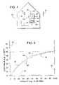
- FIG. 1is a schematic diagram of a thermostat and a heating or cooling system employing the subject invention.
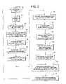
- FIG. 2is a flow chart that outlines a method according to one embodiment of the invention.
- FIG. 3is a graph illustrating one aspect of the invention.
- a thermostat 10controls a temperature conditioning unit 12 for heating or cooling a room or area within a building 14 .
- Unit 12is schematically illustrated to represent any temperature conditioning apparatus, examples of which include, but are not limited to, a gas or oil furnace, electric heater, air conditioner, and heat pump.
- thermostat 10is schematically illustrated to represent any system monitor or controller adapted to analyze input from a temperature sensor and provide certain feedback in response to the sensed temperature.
- thermostat 10include, but are not limited to, an electronic thermostat, a computer, microprocessor, microcomputer, digital circuits, analog circuits, and various combinations thereof.
- thermostat 10receives an input 16 from an indoor temperature sensor 18 and an input 20 from an outdoor temperature sensor 22 .
- Sensor 18senses the actual indoor temperature of building 14
- sensor 22senses the building's outdoor temperature.
- Thermostat 10also includes an input 24 that allows a user to select or establish a desired target indoor temperature.
- Input 24is schematically illustrated to represent any user interface, such as a dial, push button, keyboard, touch screen, etc.
- thermostat 10In response to inputs 16 , 20 and 24 , thermostat 10 provides an output signal 26 that varies the capacity of unit 12 to help maintain the actual indoor temperature within a predetermined range (e.g., a few degrees or less) of the desired target indoor temperature.
- a predetermined rangee.g., a few degrees or less
- a few examples of such methodsinclude, but are not limited to, varying the speed of a refrigerant compressor, cycling a refrigerant compressor between different stages (e.g., a first stage providing a first refrigerant flow rate and a second stage providing a second refrigerant flow rate), throttling or cycling a valve to vary the flow of refrigerant, throttling or cycling a valve to vary the flow rate of chilled water, etc.
- output signal 26cycles unit 12 on and off as needed to maintain the indoor temperature at or near the desired target indoor temperature.
- Various on/off control schemesare well known to those skilled in the art.
- thermostat 10can calculate the tolerable outdoor temperature limit (maximum for cooling systems, minimum for heating).
- the tolerable outdoor temperatureis the outdoor temperature at which unit 12 would need to operate at its maximum capacity in order to maintain an actual indoor temperature at or near a given desired target indoor temperature.
- Thermostat 10can also determine whether unit 12 needs servicing by comparing the calculated tolerable outdoor temperature limit to a predetermined specified outdoor temperature limit.
- thermostat 10can also determine the minimum or maximum achievable indoor temperature for a given outdoor temperature. To do all this (in the example of an on/off control scheme), thermostat 10 follows the control algorithm outlined in FIG. 2 .
- thermostat 10reads the outdoor temperature through feedback 20 provided by sensor 22 .
- thermostat 10reads the actual indoor temperature as sensed by temperature sensor 18 .
- a userprovides thermostat 10 with a desired target indoor temperature.
- Block 34comprises a conventional on/off control scheme that cycles unit 12 on and off to maintain the indoor temperature at or near the desired target indoor temperature. Generally, the greater the difference between the outdoor temperature and the target indoor temperature, the closer unit 12 must operate at its maximum capacity of 100% (numeral 35 in FIG. 3 ).
- the capacity of unit 12is in terms of duty cycle (i.e., the percentage of time that unit 12 is running: (on-time)/(on-time+off-time)).
- thermostat 10determines and periodically records (e.g., temporarily stores, remembers, etc.) the capacity or duty cycle at various operating conditions.
- the operating conditionsmay be described in terms of load values (e.g., the difference between the outdoor temperature and the target indoor temperature or the difference between the outdoor temperature and the actual indoor temperature).
- load valuese.g., the difference between the outdoor temperature and the target indoor temperature or the difference between the outdoor temperature and the actual indoor temperature.
- thermostat 10compares the various operating capacities or duty cycles to the load values to create performance data. The operations of blocks 40 and 42 are illustrated graphically in FIG.
- a Y-axis 44represents load values (e.g., temperature differential between the outdoor temperature and the target indoor temperature)
- an X-axis 46represents the capacity (e.g., duty cycle or percentage of on-time of unit 12 )
- data points 48represent performance data plotted as load value versus capacity.
- a linesuch as a curved line 54 or a straight line 56 can be fitted through data points 48 .
- Line 54 or 56can help in extrapolating data points 48 to predict the tolerable outdoor temperature limit at which unit 12 is expected to be able to maintain the actual indoor temperature within a predetermined range of the target indoor temperature (e.g., a predetermined range of just a few degrees). For instance, if unit 12 is used for cooling with a target indoor temperature of 70 degrees Fahrenheit, then the maximum tolerable outdoor temperature is 130 degrees (70°+60°, wherein 70° is the target temperature and 60° is the indoor/outdoor temperature differential when unit 12 is operating at its maximum capacity of a 100% duty cycle).
- the minimum tolerable outdoor temperatureis 10° (70° ⁇ 60°).
- the tolerable outdoor temperature 58can be displayed on thermostat 10 , as shown in FIG. 1 . Such a display can provide a user with an indication of how well unit 12 can handle future heating or cooling loads.
- the graph of FIG. 3is just for illustration, and that the actual data points may lie in a much different arrangement, depending on the particular temperature conditioning unit and other factors.
- data points 48are used for both cooling and heating examples, in reality, heating and cooling may generate completely different sets of data points.
- the steps performed by blocks 36 , 38 , 40 , 42 and 50do not necessarily involve actually plotting data points 48 and physically drawing a line through the points. Rather, data points 48 can be stored as numbers or coordinates, and the step of fitting a line can be performed by deriving from points 48 an equation for a curved or straight line that when extrapolated can identify a tolerable outdoor temperature limit. Such a method of fitting a line (e.g., an equation) through a set of data points is common knowledge.
- thermostat 10uses data points 48 to predict a best achievable indoor temperature for a given outdoor temperature.
- “best achievable indoor temperature”refers to the approximate expected indoor temperature that is farthest from the outdoor temperature, in the logical right direction of course.
- system 12can handle a load or indoor/outdoor temperature differential of 60°, then unit 12 should be able maintain an achievable indoor temperature of 50° (110° ⁇ 60°).
- unit 12Using the same data points 48 , in a heating mode with an outdoor temperature of 30°, unit 12 would be expected to be able to maintain an achievable indoor temperature of 90° (30°+60°).
- thermostat 10displays an achievable indoor temperature 62 to provide a user with an indication of how much extra capacity (or lack thereof) unit 12 has at a particular load condition.
- Block 64illustrates the step of establishing a specified outdoor temperature limit, i.e., the tolerable outdoor temperature limit when unit 12 is new or in perfect condition.
- a specified outdoor temperature limiti.e., the tolerable outdoor temperature limit when unit 12 is new or in perfect condition.
- the specified outdoor temperature limitprovides the user with an indication of whether the performance of unit 12 has deteriorated. If so, thermostat 10 may display a signal 68 that indicates that unit 12 may need servicing, as indicated by block 70 .
- Signal 68can be an on/off light or a written message.
Landscapes
- Engineering & Computer Science (AREA)
- Remote Sensing (AREA)
- Physics & Mathematics (AREA)
- General Physics & Mathematics (AREA)
- Automation & Control Theory (AREA)
- Air Conditioning Control Device (AREA)
Abstract
Description
1. Field of the Invention
The present invention generally relates to heating, ventilating, and air conditioning systems (HVAC systems), and more specifically to a thermostat for such a system, wherein the thermostat identifies minimum or maximum tolerable outdoor temperatures for a given desired indoor temperature and/or identifies minimum or maximum achievable indoor temperatures for a given outdoor temperature.
2. Description of Related Art
Temperature conditioning equipment, such as gas or oil furnaces, electric heaters, air conditioners, and heat pumps are often used to control or modulate the temperature of a room or other area of a building. Although there are many ways of controlling such equipment, one common method involves cycling the equipment on and off as needed.
For example, the controller disclosed in U.S. Pat. No. 4,292,813 includes an off-time counter that determines the duration of the off cycle. The counter is incremented when the measured run-time of the equipment is less than a desired minimum and is decremented when the measured run-time is greater than a desired maximum. If the measured run-time is within a desired range, then the prior off-time is maintained.
As another example, U.S. Pat. No. 5,647,533 discloses a controller that varies the run-time of a heat pump. The speed of an indoor blower is adjusted whenever the operating run-time fraction of a heat cycle passes a predetermined threshold, unless the run-time fraction is sufficiently changed compared to a previous run-time fraction.
Regardless of the control scheme, many factors can reduce the heating or cooling effectiveness of temperature conditioning equipment. The equipment's heating or cooling effectiveness is a function of several factors, such as the equipment's designed capacity; the cleanliness of various heat exchangers and air filters; refrigerant charge; thermal load, which can vary with the outdoor temperature and the desired indoor temperature; and mechanical condition of a compressor or blower associated with the equipment.
To address diminished or otherwise insufficient capacity, some controllers include provisions for analyzing the condition of the equipment and its surroundings. For example, U.S. Pat. No. 4,574,871 discloses a diagnostic thermostat or monitor that measures run time for a heat pump compressor and compares expected run times for a particular outdoor temperature. An alarm signal identifies when the system fails to operate within expected parameters.
Another example of a diagnostic thermostat is disclosed in U.S. Pat. No. 4,685,615. Here, the thermostat senses the outdoor temperature and accumulates degree-days and run-time of a heating or cooling unit. The thermostat can calculate, store, and display energy used per degree-day for a given period to indicate the performance or efficiency of the building and its heating or cooling system.
U.S. Pat. No. 5,729,474 discloses another method of monitoring the effectiveness of a heating or cooling system. An efficiency value representing the system's ability to change temperature in a predetermined zone is repeatedly computed. Comparing a current efficiency value with a previous efficiency value helps identify deterioration of the system's ability to heat or cool. In response to a predetermined amount of deterioration, a control signal indicates a need for inspection of the system before the system fails completely.
However, a disadvantage of current thermostats is their inability to quantify certain operating limits of heating or cooling systems. For example, conventional thermostats fail to predetermine the maximum outdoor temperature that a particular cooling system can tolerate while still maintaining the indoor temperature at its desired level. And thermostats typically fail to predetermine the minimum or maximum achievable indoor temperature for a given outdoor temperature.
To overcome the drawbacks of current thermostats, it is an object of some embodiments of the invention to provide a method of determining a maximum or minimum tolerable outdoor temperature that a particular heating or cooling system can tolerate while still maintaining the indoor temperature at its desired level, wherein the method is based on sampling the system's performance at various loads.
Another object of some embodiments of the invention is to sample a system's performance at various loads to create data through which a straight or curved line can be fitted, whereby extrapolating along the line helps identify a maximum or minimum tolerable outdoor temperature.
Another object of some embodiments is to provide a method that helps determine a minimum or maximum achievable indoor temperature for a given outdoor temperature.
Another object of some embodiments is to compare a system's tolerable outdoor temperature limit to an optimum or otherwise specified temperature limit to determine whether the system needs servicing.
Yet, another object of some embodiments is to provide a user with feedback that indicates when a system may need servicing.
A further object of some embodiments is to provide a user with feedback that indicates a system's tolerable outdoor temperature limit for a given indoor temperature.
A still further object of some embodiments is to provide a user with feedback that indicates a system's best achievable indoor temperature limit for a given outdoor temperature.
These and other objects of the invention are provided by method of determining a tolerable outdoor temperature limit for a temperature conditioning apparatus. The method includes sampling the system's performance at various loads to create a set of data, and extrapolating the data to identify at what outdoor temperature the system will need to operate continuously to maintain a desired indoor temperature.
The present invention provides a method of determining a tolerable outdoor temperature limit for a temperature conditioning apparatus having a capacity that varies up to a maximum capacity. The method comprises determining a target indoor temperature; sensing an outdoor temperature; sensing an actual indoor temperature; repeatedly comparing the outdoor temperature to at least one of the actual indoor temperature and the target indoor temperature to determine a plurality of load values; and varying the capacity of the temperature conditioning apparatus to help maintain the actual indoor temperature within a predetermined range of the target indoor temperature. The method also comprises creating performance data by comparing the capacity to the plurality of load values; and extrapolating the performance data to the maximum capacity to predict the tolerable outdoor temperature limit at which the temperature conditioning apparatus is expected to be able to maintain the actual indoor temperature within the predetermined range of the target indoor temperature.
The present invention also provides a method of determining a tolerable outdoor temperature limit for a temperature conditioning apparatus. The method comprises determining a target indoor temperature; sensing an outdoor temperature; sensing an actual indoor temperature; repeatedly comparing the outdoor temperature to at least one of the actual indoor temperature and the target indoor temperature to determine a plurality of load values; and cycling the temperature conditioning apparatus on and off to create a plurality of on-times and plurality of off-times, whereby cycling the temperature conditioning apparatus helps maintain the actual indoor temperature within a predetermined range of the target indoor temperature. The method also comprises determining a plurality of duty cycles of the temperature conditioning apparatus by comparing the plurality of on-times to the plurality of off-times; creating performance data by comparing the plurality of duty cycles to the plurality of load values; and extrapolating the performance data to predict the tolerable outdoor temperature limit at which the temperature conditioning apparatus is expected to be able to maintain the actual indoor temperature within the predetermined range of the target indoor temperature.
The present invention further provides a method of determining a tolerable outdoor temperature limit for a temperature conditioning apparatus. The method comprises determining a target indoor temperature; sensing an outdoor temperature; sensing an actual indoor temperature; repeatedly comparing the outdoor temperature to at least one of the actual indoor temperature and the target indoor temperature to determine a plurality of load values. cycling the temperature conditioning apparatus on and off to create a plurality of on-times and plurality of off-times, whereby cycling the temperature conditioning apparatus helps maintain the actual indoor temperature within a predetermined range of the target indoor temperature. The method also comprises determining a plurality of duty cycles of the temperature conditioning apparatus by comparing the plurality of on-times to the plurality of off-times; creating performance data by comparing the plurality of duty cycles to the plurality of load values; based on the performance data, predicting the tolerable outdoor temperature limit at which the temperature conditioning apparatus is expected to be able to maintain the indoor temperature within the predetermined range of the target indoor temperature; establishing a specified temperature limit; comparing the tolerable outdoor temperature limit to the specified temperature limit, thereby creating a comparison; and displaying a signal that reflects the comparison.
The present invention still further provides a method of determining a tolerable outdoor temperature limit for a temperature conditioning apparatus. The method comprises determining a target indoor temperature; sensing an outdoor temperature; sensing an actual indoor temperature; repeatedly comparing the outdoor temperature to at least one of the actual indoor temperature and the target indoor temperature to determine a plurality of load values. cycling the temperature conditioning apparatus on and off to create a plurality of on-times and plurality of off-times, whereby cycling the temperature conditioning apparatus helps maintain the actual indoor temperature within a predetermined range of the target indoor temperature. The method also comprises determining a plurality of duty cycles of the temperature conditioning apparatus by comparing the plurality of on-times to the plurality of off-times; creating performance data by comparing the plurality of duty cycles to the plurality of load values; fitting a line through the performance data; extrapolating the performance data via the line to predict the tolerable outdoor temperature limit at which the temperature conditioning apparatus is expected to be able to maintain the actual indoor temperature within the predetermined range of the target indoor temperature; establishing a specified temperature limit; comparing the tolerable outdoor temperature limit to the specified temperature limit, thereby creating a comparison; and displaying a signal that reflects the comparison, wherein the signal indicates that the temperature conditioning apparatus may need servicing.
The present invention yet further provides a temperature conditioning apparatus having a capacity that varies up to a maximum capacity. The apparatus comprises components for determining a target indoor temperature; components for sensing an outdoor temperature; components for sensing an actual indoor temperature; and components for repeatedly comparing the outdoor temperature to at least one of the actual indoor temperature and the target indoor temperature to determine a plurality of load values. The apparatus also comprises components for varying the capacity of the temperature conditioning apparatus to help maintain the actual indoor temperature within a predetermined range of the target indoor temperature; components for creating performance data by comparing the capacity to the plurality of load values; and components for extrapolating the performance data to the maximum capacity to predict the tolerable outdoor temperature limit at which the temperature conditioning apparatus is expected to be able to maintain the actual indoor temperature within the predetermined range of the target indoor temperature.
The present invention moreover provides a temperature conditioning apparatus. The apparatus comprises a device for determining a target indoor temperature; a device for sensing an outdoor temperature; a device for sensing an actual indoor temperature; and a device for repeatedly comparing the outdoor temperature to at least one of the actual indoor temperature and the target indoor temperature to determine a plurality of load values. The apparatus further comprises a device for cycling the temperature conditioning apparatus on and off to create a plurality of on-times and plurality of off-times, whereby cycling the temperature conditioning apparatus helps maintain the actual indoor temperature within a predetermined range of the target indoor temperature. The apparatus also comprises a device for determining a plurality of duty cycles of the temperature conditioning apparatus by comparing the plurality of on-times to the plurality of off-times; a device for creating performance data by comparing the plurality of duty cycles to the plurality of load values; and a device for extrapolating the performance data to predict the tolerable outdoor temperature limit at which the temperature conditioning apparatus is expected to be able to maintain the actual indoor temperature within the predetermined range of the target indoor temperature.
Referring toFIG. 1 , athermostat 10 controls atemperature conditioning unit 12 for heating or cooling a room or area within abuilding 14.Unit 12 is schematically illustrated to represent any temperature conditioning apparatus, examples of which include, but are not limited to, a gas or oil furnace, electric heater, air conditioner, and heat pump.
In some embodiments of the invention,thermostat 10 receives aninput 16 from anindoor temperature sensor 18 and aninput 20 from anoutdoor temperature sensor 22.Sensor 18 senses the actual indoor temperature of building14, andsensor 22 senses the building's outdoor temperature.Thermostat 10 also includes aninput 24 that allows a user to select or establish a desired target indoor temperature.Input 24 is schematically illustrated to represent any user interface, such as a dial, push button, keyboard, touch screen, etc.
In response toinputs thermostat 10 provides anoutput signal 26 that varies the capacity ofunit 12 to help maintain the actual indoor temperature within a predetermined range (e.g., a few degrees or less) of the desired target indoor temperature. This process is schematically illustrated inFIG. 1 to represent all methods of varying the heating or cooling capacity of a temperature conditioning apparatus. A few examples of such methods include, but are not limited to, varying the speed of a refrigerant compressor, cycling a refrigerant compressor between different stages (e.g., a first stage providing a first refrigerant flow rate and a second stage providing a second refrigerant flow rate), throttling or cycling a valve to vary the flow of refrigerant, throttling or cycling a valve to vary the flow rate of chilled water, etc. In one embodiment of the invention,output signal 26cycles unit 12 on and off as needed to maintain the indoor temperature at or near the desired target indoor temperature. Various on/off control schemes are well known to those skilled in the art.
In addition to controllingunit 12,thermostat 10 can calculate the tolerable outdoor temperature limit (maximum for cooling systems, minimum for heating). The tolerable outdoor temperature is the outdoor temperature at whichunit 12 would need to operate at its maximum capacity in order to maintain an actual indoor temperature at or near a given desired target indoor temperature.Thermostat 10 can also determine whetherunit 12 needs servicing by comparing the calculated tolerable outdoor temperature limit to a predetermined specified outdoor temperature limit. In some embodiments,thermostat 10 can also determine the minimum or maximum achievable indoor temperature for a given outdoor temperature. To do all this (in the example of an on/off control scheme),thermostat 10 follows the control algorithm outlined inFIG. 2 .
Incontrol block 28,thermostat 10 reads the outdoor temperature throughfeedback 20 provided bysensor 22. Inblock 30,thermostat 10 reads the actual indoor temperature as sensed bytemperature sensor 18. Inblock 32, a user providesthermostat 10 with a desired target indoor temperature.Block 34 comprises a conventional on/off control scheme that cyclesunit 12 on and off to maintain the indoor temperature at or near the desired target indoor temperature. Generally, the greater the difference between the outdoor temperature and the target indoor temperature, thecloser unit 12 must operate at its maximum capacity of 100% (numeral35 inFIG. 3 ). For an on/off control scheme, the capacity ofunit 12 is in terms of duty cycle (i.e., the percentage of time thatunit 12 is running: (on-time)/(on-time+off-time)).
In blocks36 and38,thermostat 10 determines and periodically records (e.g., temporarily stores, remembers, etc.) the capacity or duty cycle at various operating conditions. The operating conditions may be described in terms of load values (e.g., the difference between the outdoor temperature and the target indoor temperature or the difference between the outdoor temperature and the actual indoor temperature). In blocks40 and42,thermostat 10 compares the various operating capacities or duty cycles to the load values to create performance data. The operations ofblocks FIG. 3 , wherein a Y-axis 44 represents load values (e.g., temperature differential between the outdoor temperature and the target indoor temperature), anX-axis 46 represents the capacity (e.g., duty cycle or percentage of on-time of unit12), anddata points 48 represent performance data plotted as load value versus capacity.
In blocks50 and52, a line, such as acurved line 54 or astraight line 56 can be fitted through data points48.Line data points 48 to predict the tolerable outdoor temperature limit at whichunit 12 is expected to be able to maintain the actual indoor temperature within a predetermined range of the target indoor temperature (e.g., a predetermined range of just a few degrees). For instance, ifunit 12 is used for cooling with a target indoor temperature of 70 degrees Fahrenheit, then the maximum tolerable outdoor temperature is 130 degrees (70°+60°, wherein 70° is the target temperature and 60° is the indoor/outdoor temperature differential whenunit 12 is operating at its maximum capacity of a 100% duty cycle). Or, ifunit 12 is used for heating with a target temperature of 70°, then the minimum tolerable outdoor temperature is 10° (70°−60°). Once determined, the tolerableoutdoor temperature 58 can be displayed onthermostat 10, as shown inFIG. 1 . Such a display can provide a user with an indication of how wellunit 12 can handle future heating or cooling loads.
It should be noted that the graph ofFIG. 3 is just for illustration, and that the actual data points may lie in a much different arrangement, depending on the particular temperature conditioning unit and other factors. Although data points48 are used for both cooling and heating examples, in reality, heating and cooling may generate completely different sets of data points. Moreover, the steps performed byblocks data points 48 and physically drawing a line through the points. Rather, data points48 can be stored as numbers or coordinates, and the step of fitting a line can be performed by deriving frompoints 48 an equation for a curved or straight line that when extrapolated can identify a tolerable outdoor temperature limit. Such a method of fitting a line (e.g., an equation) through a set of data points is common knowledge.
Inblock 60,thermostat 10 usesdata points 48 to predict a best achievable indoor temperature for a given outdoor temperature. The expression, “best achievable indoor temperature” refers to the approximate expected indoor temperature that is farthest from the outdoor temperature, in the logical right direction of course. In a cooling mode, for example, if the outdoor temperature is 110°, anddata points 48 indicate that at a maximum capacity or 100% duty cycle,system 12 can handle a load or indoor/outdoor temperature differential of 60°, thenunit 12 should be able maintain an achievable indoor temperature of 50° (110°−60°). Using the same data points48, in a heating mode with an outdoor temperature of 30°,unit 12 would be expected to be able to maintain an achievable indoor temperature of 90° (30°+60°). InFIG. 1 ,thermostat 10 displays an achievableindoor temperature 62 to provide a user with an indication of how much extra capacity (or lack thereof)unit 12 has at a particular load condition.
The arrows interconnecting the blocks ofFIG. 2 are there to indicate that the algorithm process is repeated and ongoing.
Although the invention is described with reference to a preferred embodiment, it should be appreciated by those skilled in the art that other variations are well within the scope of the invention. For example, rather than sensing temperature, other conditions such as indoor air quality, carbon dioxide level, carbon monoxide level, humidity, pressure or the like may be sensed in accordance with the invention. Therefore, the scope of the invention is to be determined by reference to the claims, which follow.
Claims (59)
1. A method of determining a tolerable outdoor temperature limit for a temperature conditioning apparatus having a capacity that varies up to a maximum capacity, comprising:
determining a target indoor temperature;
sensing an outdoor temperature;
sensing an actual indoor temperature;
repeatedly comparing the outdoor temperature to at least one of the actual indoor temperature and the target indoor temperature to determine a plurality of load values;
varying the capacity of the temperature conditioning apparatus to help maintain the actual indoor temperature within a predetermined range of the target indoor temperature;
creating performance data by comparing the capacity to the plurality of load values; and
extrapolating the performance data to the maximum capacity to predict the tolerable outdoor temperature limit at which the temperature conditioning apparatus is expected to be able to maintain the actual indoor temperature within the predetermined range of the target indoor temperature.
2. The method ofclaim 1 , wherein the step of varying the capacity is performed by cycling the temperature conditioning apparatus on and off to create a plurality of on-times and plurality of off-times.
3. The method ofclaim 2 , further comprising determining a plurality of duty cycles of the temperature conditioning apparatus by comparing the plurality of on-times to the plurality of off-times.
4. The method ofclaim 3 , wherein the step of creating performance data is performed by comparing the plurality of duty cycles to the plurality of load values.
5. The method ofclaim 1 , wherein the temperature conditioning apparatus is a cooling apparatus.
6. The method ofclaim 1 , wherein the temperature conditioning apparatus is a heating apparatus.
7. The method ofclaim 1 , further comprising fitting a straight line through the performance data.
8. The method ofclaim 1 , further comprising fitting a curved line through the performance data.
9. The method ofclaim 1 , further comprising:
establishing a specified temperature limit; and
comparing the tolerable outdoor temperature limit to the specified temperature limit, thereby creating a comparison.
10. The method ofclaim 6 , displaying a signal that reflects the comparison.
11. The method ofclaim 10 , wherein the signal indicates that the temperature conditioning apparatus may need servicing.
12. The method ofclaim 1 , further comprising displaying the tolerable outdoor temperature limit.
13. The method ofclaim 1 , further comprising predicting a best achievable indoor temperature based on the performance data and the outdoor temperature.
14. The method ofclaim 13 , further comprising displaying the best achievable indoor temperature.
15. A method of determining a tolerable outdoor temperature limit for a temperature conditioning apparatus, comprising:
determining a target indoor temperature;
sensing an outdoor temperature;
sensing an actual indoor temperature;
repeatedly comparing the outdoor temperature to at least one of the actual indoor temperature and the target indoor temperature to determine a plurality of load values;
cycling the temperature conditioning apparatus on and off to create a plurality of on-times and plurality of off-times, whereby cycling the temperature conditioning apparatus helps maintain the actual indoor temperature within a predetermined range of the target indoor temperature;
determining a plurality of duty cycles of the temperature conditioning apparatus by comparing the plurality of on-times to the plurality of off-times;
creating performance data by comparing the plurality of duty cycles to the plurality of load values; and
extrapolating the performance data to predict the tolerable outdoor temperature limit at which the temperature conditioning apparatus is expected to be able to maintain the actual indoor temperature within the predetermined range of the target indoor temperature.
16. The method ofclaim 15 , wherein the temperature conditioning apparatus is a cooling apparatus.
17. The method ofclaim 15 , wherein the temperature conditioning apparatus is a heating apparatus.
18. The method ofclaim 15 , further comprising fitting a straight line through the performance data.
19. The method ofclaim 15 , further comprising fitting a curved line through the performance data.
20. The method ofclaim 15 , further comprising:
establishing a specified temperature limit; and
comparing the tolerable outdoor temperature limit to the specified temperature limit, thereby creating a comparison.
21. The method ofclaim 20 , displaying a signal that reflects the comparison.
22. The method ofclaim 21 , wherein the signal indicates that the temperature conditioning apparatus may need servicing.
23. The method ofclaim 15 , further comprising displaying the tolerable outdoor temperature limit.
24. The method ofclaim 15 , further comprising predicting a best achievable indoor temperature based on the performance data and the outdoor temperature.
25. The method ofclaim 24 , further comprising displaying the best achievable indoor temperature.
26. A method of determining a tolerable outdoor temperature limit for a temperature conditioning apparatus, comprising:
determining a target indoor temperature;
sensing an outdoor temperature;
sensing an actual indoor temperature;
repeatedly comparing the outdoor temperature to at least one of the actual indoor temperature and the target indoor temperature to determine a plurality of load values;
cycling the temperature conditioning apparatus on and off to create a plurality of on-times and plurality of off-times, whereby cycling the temperature conditioning apparatus helps maintain the actual indoor temperature within a predetermined range of the target indoor temperature;
determining a plurality of duty cycles of the temperature conditioning apparatus by comparing the plurality of on-times to the plurality of off-times;
creating performance data by comparing the plurality of duty cycles to the plurality of load values;
based on the performance data, predicting the tolerable outdoor temperature limit at which the temperature conditioning apparatus is expected to be able to maintain the indoor temperature within the predetermined range of the target indoor temperature;
establishing a specified temperature limit;
comparing the tolerable outdoor temperature limit to the specified temperature limit, thereby creating a comparison; and
displaying a signal that reflects the comparison.
27. The method ofclaim 26 , wherein the temperature conditioning apparatus is a cooling apparatus.
28. The method ofclaim 26 , wherein the temperature conditioning apparatus is a heating apparatus.
29. The method ofclaim 26 , further comprising fitting a straight line through the performance data.
30. The method ofclaim 26 , further comprising fitting a curved line through the performance data.
31. The method ofclaim 26 , wherein the signal indicates that the temperature conditioning apparatus may need servicing.
32. The method ofclaim 26 , further comprising displaying the tolerable outdoor temperature limit.
33. The method ofclaim 26 , further comprising predicting a best achievable indoor temperature based on the performance data and the outdoor temperature.
34. The method ofclaim 33 , further comprising displaying the best achievable indoor temperature.
35. A method of determining a tolerable outdoor temperature limit for a temperature conditioning apparatus, comprising:
determining a target indoor temperature;
sensing an outdoor temperature;
sensing an actual indoor temperature;
repeatedly comparing the outdoor temperature to at least one of the actual indoor temperature and the target indoor temperature to determine a plurality of load values;
cycling the temperature conditioning apparatus on and off to create a plurality of on-times and plurality of off-times, whereby cycling the temperature conditioning apparatus helps maintain the actual indoor temperature within a predetermined range of the target indoor temperature;
determining a plurality of duty cycles of the temperature conditioning apparatus by comparing the plurality of on-times to the plurality of off-times;
creating performance data by comparing the plurality of duty cycles to the plurality of load values;
fitting a line through the performance data;
extrapolating the performance data via the line to predict the tolerable outdoor temperature limit at which the temperature conditioning apparatus is expected to be able to maintain the actual indoor temperature within the predetermined range of the target indoor temperature;
establishing a specified temperature limit;
comparing the tolerable outdoor temperature limit to the specified temperature limit, thereby creating a comparison; and
displaying a signal that reflects the comparison, wherein the signal indicates that the temperature conditioning apparatus may need servicing.
36. The method ofclaim 35 , wherein the temperature conditioning apparatus is a cooling apparatus.
37. The method ofclaim 35 , wherein the temperature conditioning apparatus is a heating apparatus.
38. The method ofclaim 35 , wherein the line is a straight line.
39. The method ofclaim 35 , wherein the line is a curved line.
40. The method ofclaim 35 , further comprising displaying the tolerable outdoor temperature limit.
41. The method ofclaim 35 , further comprising predicting a best achievable indoor temperature based on the performance data and the outdoor temperature.
42. The method ofclaim 41 , further comprising displaying the best achievable indoor temperature.
43. A method of determining a tolerable outdoor limit for a conditioning apparatus having a capacity that varies up to a maximum capacity, comprising:
determining a target indoor condition;
sensing an outdoor condition;
sensing an actual indoor condition;
repeatedly comparing the outdoor condition to at least one of the actual indoor condition and the target indoor condition to determine a plurality of load values;
varying the capacity of the conditioning apparatus to help maintain the actual indoor condition within a predetermined range of the target indoor condition;
creating performance data by comparing the capacity to the plurality of load values; and
extrapolating the performance data to the maximum capacity to predict the tolerable outdoor condition limit at which the conditioning apparatus is expected to be able to maintain the actual indoor condition within the predetermined range of the target indoor condition.
44. The method ofclaim 43 , wherein the step of varying the capacity is performed by cycling the conditioning apparatus on and off to create a plurality of on-times and plurality of off-times.
45. The method ofclaim 44 , further comprising determining a plurality of duty cycles of the conditioning apparatus by comparing the plurality of on-times to the plurality of off-times.
46. The method ofclaim 45 , wherein the step of creating performance data is performed by comparing the plurality of duty cycles to the plurality of load values.
47. The method ofclaim 43 , wherein the conditioning apparatus is a temperature cooling apparatus.
48. The method ofclaim 43 , wherein the conditioning apparatus is a temperature heating apparatus.
49. A temperature conditioning apparatus having a capacity that varies up to a maximum capacity, comprising:
means for determining a target indoor temperature;
means for sensing an outdoor temperature;
means for sensing an actual indoor temperature;
means for repeatedly comparing the outdoor temperature to at least one of the actual indoor temperature and the target indoor temperature to determine a plurality of load values;
means for varying the capacity of the temperature conditioning apparatus to help maintain the actual indoor temperature within a predetermined range of the target indoor temperature;
means for creating performance data by comparing the capacity to the plurality of load values; and
means for extrapolating the performance data to the maximum capacity to predict the tolerable outdoor temperature limit at which the temperature conditioning apparatus is expected to be able to maintain the actual indoor temperature within the predetermined range of the target indoor temperature.
50. The apparatus ofclaim 49 , wherein the step of varying the capacity further includes means for cycling the temperature conditioning apparatus on and off to create a plurality of on-times and plurality of off-times.
51. The apparatus ofclaim 50 , further comprising means for determining a plurality of duty cycles of the temperature conditioning apparatus by comparing the plurality of on-times to the plurality of off-times.
52. The apparatus ofclaim 51 , wherein the step of creating performance data includes means for comparing the plurality of duty cycles to the plurality of load values.
53. The apparatus ofclaim 49 , further comprising:
means for establishing a specified temperature limit; and
means for comparing the tolerable outdoor temperature limit to the specified temperature limit, thereby creating a comparison.
54. A temperature conditioning apparatus, comprising:
means for determining a target indoor temperature;
means for sensing an outdoor temperature;
means for sensing an actual indoor temperature;
means for repeatedly comparing the outdoor temperature to at least one of the actual indoor temperature and the target indoor temperature to determine a plurality of load values;
means for cycling the temperature conditioning apparatus on and off to create a plurality of on-times and plurality of off-times, whereby cycling the temperature conditioning apparatus helps maintain the actual indoor temperature within a predetermined range of the target indoor temperature;
means for determining a plurality of duty cycles of the temperature conditioning apparatus by comparing the plurality of on-times to the plurality of off-times;
means for creating performance data by comparing the plurality of duty cycles to the plurality of load values; and
means for extrapolating the performance data to predict the tolerable outdoor temperature limit at which the temperature conditioning apparatus is expected to be able to maintain the actual indoor temperature within the predetermined range of the target indoor temperature.
55. The apparatus ofclaim 54 , further comprising:
means for establishing a specified temperature limit; and
means for comparing the tolerable outdoor temperature limit to the specified temperature limit, thereby creating a comparison.
56. The apparatus ofclaim 55 further including means for, displaying a signal that reflects the comparison.
57. The apparatus ofclaim 56 , wherein the signal indicates that the temperature conditioning apparatus may need servicing.
58. The apparatus ofclaim 54 , further comprising means for displaying the tolerable outdoor temperature limit.
59. The apparatus ofclaim 54 , further comprising means for predicting a best achievable indoor temperature based on the performance data and the outdoor temperature.
Priority Applications (1)
| Application Number | Priority Date | Filing Date | Title |
|---|---|---|---|
| US10/283,398US7024283B2 (en) | 2002-10-28 | 2002-10-28 | Method of determining indoor or outdoor temperature limits |
Applications Claiming Priority (1)
| Application Number | Priority Date | Filing Date | Title |
|---|---|---|---|
| US10/283,398US7024283B2 (en) | 2002-10-28 | 2002-10-28 | Method of determining indoor or outdoor temperature limits |
Publications (2)
| Publication Number | Publication Date |
|---|---|
| US20040083029A1 US20040083029A1 (en) | 2004-04-29 |
| US7024283B2true US7024283B2 (en) | 2006-04-04 |
Family
ID=32107515
Family Applications (1)
| Application Number | Title | Priority Date | Filing Date |
|---|---|---|---|
| US10/283,398Expired - LifetimeUS7024283B2 (en) | 2002-10-28 | 2002-10-28 | Method of determining indoor or outdoor temperature limits |
Country Status (1)
| Country | Link |
|---|---|
| US (1) | US7024283B2 (en) |
Cited By (76)
| Publication number | Priority date | Publication date | Assignee | Title |
|---|---|---|---|---|
| US20100106543A1 (en)* | 2008-10-28 | 2010-04-29 | Honeywell International Inc. | Building management configuration system |
| US20100131653A1 (en)* | 2008-11-21 | 2010-05-27 | Honeywell International, Inc. | Building control system user interface with pinned display feature |
| US20100131877A1 (en)* | 2008-11-21 | 2010-05-27 | Honeywell International, Inc. | Building control system user interface with docking feature |
| US20100298992A1 (en)* | 2009-05-21 | 2010-11-25 | Dmitriy Knyazev | System for Controlling the Heating and Housing Units in a Building |
| US20100312397A1 (en)* | 2009-06-08 | 2010-12-09 | George Josmon C | Environment control system |
| US20100312396A1 (en)* | 2009-06-08 | 2010-12-09 | George Josmon C | Environment control system |
| US20110010654A1 (en)* | 2009-05-11 | 2011-01-13 | Honeywell International Inc. | High volume alarm managment system |
| US20110083077A1 (en)* | 2008-10-28 | 2011-04-07 | Honeywell International Inc. | Site controller discovery and import system |
| US20110093493A1 (en)* | 2008-10-28 | 2011-04-21 | Honeywell International Inc. | Building management system site categories |
| US20110196539A1 (en)* | 2010-02-10 | 2011-08-11 | Honeywell International Inc. | Multi-site controller batch update system |
| US20110225580A1 (en)* | 2010-03-11 | 2011-09-15 | Honeywell International Inc. | Offline configuration and download approach |
| USD648642S1 (en) | 2009-10-21 | 2011-11-15 | Lennox Industries Inc. | Thin cover plate for an electronic system controller |
| USD648641S1 (en) | 2009-10-21 | 2011-11-15 | Lennox Industries Inc. | Thin cover plate for an electronic system controller |
| US8224763B2 (en) | 2009-05-11 | 2012-07-17 | Honeywell International Inc. | Signal management system for building systems |
| US8239066B2 (en) | 2008-10-27 | 2012-08-07 | Lennox Industries Inc. | System and method of use for a user interface dashboard of a heating, ventilation and air conditioning network |
| US8255086B2 (en) | 2008-10-27 | 2012-08-28 | Lennox Industries Inc. | System recovery in a heating, ventilation and air conditioning network |
| US8260444B2 (en) | 2010-02-17 | 2012-09-04 | Lennox Industries Inc. | Auxiliary controller of a HVAC system |
| US8295981B2 (en) | 2008-10-27 | 2012-10-23 | Lennox Industries Inc. | Device commissioning in a heating, ventilation and air conditioning network |
| US8352047B2 (en) | 2009-12-21 | 2013-01-08 | Honeywell International Inc. | Approaches for shifting a schedule |
| US8352081B2 (en) | 2008-10-27 | 2013-01-08 | Lennox Industries Inc. | Communication protocol system and method for a distributed-architecture heating, ventilation and air conditioning network |
| US8352080B2 (en) | 2008-10-27 | 2013-01-08 | Lennox Industries Inc. | Communication protocol system and method for a distributed-architecture heating, ventilation and air conditioning network |
| US8433446B2 (en) | 2008-10-27 | 2013-04-30 | Lennox Industries, Inc. | Alarm and diagnostics system and method for a distributed-architecture heating, ventilation and air conditioning network |
| US8437878B2 (en) | 2008-10-27 | 2013-05-07 | Lennox Industries Inc. | Alarm and diagnostics system and method for a distributed architecture heating, ventilation and air conditioning network |
| US8437877B2 (en) | 2008-10-27 | 2013-05-07 | Lennox Industries Inc. | System recovery in a heating, ventilation and air conditioning network |
| US8442693B2 (en) | 2008-10-27 | 2013-05-14 | Lennox Industries, Inc. | System and method of use for a user interface dashboard of a heating, ventilation and air conditioning network |
| US8452906B2 (en) | 2008-10-27 | 2013-05-28 | Lennox Industries, Inc. | Communication protocol system and method for a distributed-architecture heating, ventilation and air conditioning network |
| US8452456B2 (en) | 2008-10-27 | 2013-05-28 | Lennox Industries Inc. | System and method of use for a user interface dashboard of a heating, ventilation and air conditioning network |
| US8463443B2 (en) | 2008-10-27 | 2013-06-11 | Lennox Industries, Inc. | Memory recovery scheme and data structure in a heating, ventilation and air conditioning network |
| US8463442B2 (en) | 2008-10-27 | 2013-06-11 | Lennox Industries, Inc. | Alarm and diagnostics system and method for a distributed architecture heating, ventilation and air conditioning network |
| US8543243B2 (en) | 2008-10-27 | 2013-09-24 | Lennox Industries, Inc. | System and method of use for a user interface dashboard of a heating, ventilation and air conditioning network |
| US8548630B2 (en) | 2008-10-27 | 2013-10-01 | Lennox Industries, Inc. | Alarm and diagnostics system and method for a distributed-architecture heating, ventilation and air conditioning network |
| US8560125B2 (en) | 2008-10-27 | 2013-10-15 | Lennox Industries | Communication protocol system and method for a distributed-architecture heating, ventilation and air conditioning network |
| US8564400B2 (en) | 2008-10-27 | 2013-10-22 | Lennox Industries, Inc. | Communication protocol system and method for a distributed-architecture heating, ventilation and air conditioning network |
| US8600558B2 (en) | 2008-10-27 | 2013-12-03 | Lennox Industries Inc. | System recovery in a heating, ventilation and air conditioning network |
| US8600559B2 (en) | 2008-10-27 | 2013-12-03 | Lennox Industries Inc. | Method of controlling equipment in a heating, ventilation and air conditioning network |
| US8615326B2 (en) | 2008-10-27 | 2013-12-24 | Lennox Industries Inc. | System and method of use for a user interface dashboard of a heating, ventilation and air conditioning network |
| US8648706B2 (en) | 2010-06-24 | 2014-02-11 | Honeywell International Inc. | Alarm management system having an escalation strategy |
| US8655491B2 (en) | 2008-10-27 | 2014-02-18 | Lennox Industries Inc. | Alarm and diagnostics system and method for a distributed architecture heating, ventilation and air conditioning network |
| US8655490B2 (en) | 2008-10-27 | 2014-02-18 | Lennox Industries, Inc. | System and method of use for a user interface dashboard of a heating, ventilation and air conditioning network |
| US8661165B2 (en) | 2008-10-27 | 2014-02-25 | Lennox Industries, Inc. | Device abstraction system and method for a distributed architecture heating, ventilation and air conditioning system |
| US8694164B2 (en) | 2008-10-27 | 2014-04-08 | Lennox Industries, Inc. | Interactive user guidance interface for a heating, ventilation and air conditioning system |
| US8725298B2 (en) | 2008-10-27 | 2014-05-13 | Lennox Industries, Inc. | Alarm and diagnostics system and method for a distributed architecture heating, ventilation and conditioning network |
| US8744629B2 (en) | 2008-10-27 | 2014-06-03 | Lennox Industries Inc. | System and method of use for a user interface dashboard of a heating, ventilation and air conditioning network |
| US8762666B2 (en) | 2008-10-27 | 2014-06-24 | Lennox Industries, Inc. | Backup and restoration of operation control data in a heating, ventilation and air conditioning network |
| US8774210B2 (en) | 2008-10-27 | 2014-07-08 | Lennox Industries, Inc. | Communication protocol system and method for a distributed-architecture heating, ventilation and air conditioning network |
| US8788100B2 (en) | 2008-10-27 | 2014-07-22 | Lennox Industries Inc. | System and method for zoning a distributed-architecture heating, ventilation and air conditioning network |
| US8798796B2 (en) | 2008-10-27 | 2014-08-05 | Lennox Industries Inc. | General control techniques in a heating, ventilation and air conditioning network |
| US8802981B2 (en) | 2008-10-27 | 2014-08-12 | Lennox Industries Inc. | Flush wall mount thermostat and in-set mounting plate for a heating, ventilation and air conditioning system |
| US8819562B2 (en) | 2010-09-30 | 2014-08-26 | Honeywell International Inc. | Quick connect and disconnect, base line configuration, and style configurator |
| US8850347B2 (en) | 2010-09-30 | 2014-09-30 | Honeywell International Inc. | User interface list control system |
| US8855825B2 (en) | 2008-10-27 | 2014-10-07 | Lennox Industries Inc. | Device abstraction system and method for a distributed-architecture heating, ventilation and air conditioning system |
| US8874815B2 (en) | 2008-10-27 | 2014-10-28 | Lennox Industries, Inc. | Communication protocol system and method for a distributed architecture heating, ventilation and air conditioning network |
| US8890675B2 (en) | 2010-06-02 | 2014-11-18 | Honeywell International Inc. | Site and alarm prioritization system |
| US8892797B2 (en) | 2008-10-27 | 2014-11-18 | Lennox Industries Inc. | Communication protocol system and method for a distributed-architecture heating, ventilation and air conditioning network |
| US8977794B2 (en) | 2008-10-27 | 2015-03-10 | Lennox Industries, Inc. | Communication protocol system and method for a distributed-architecture heating, ventilation and air conditioning network |
| US8994539B2 (en) | 2008-10-27 | 2015-03-31 | Lennox Industries, Inc. | Alarm and diagnostics system and method for a distributed-architecture heating, ventilation and air conditioning network |
| US9152155B2 (en) | 2008-10-27 | 2015-10-06 | Lennox Industries Inc. | Device abstraction system and method for a distributed-architecture heating, ventilation and air conditioning system |
| US9213539B2 (en) | 2010-12-23 | 2015-12-15 | Honeywell International Inc. | System having a building control device with on-demand outside server functionality |
| US9223839B2 (en) | 2012-02-22 | 2015-12-29 | Honeywell International Inc. | Supervisor history view wizard |
| US9261888B2 (en) | 2008-10-27 | 2016-02-16 | Lennox Industries Inc. | System and method of use for a user interface dashboard of a heating, ventilation and air conditioning network |
| US9268345B2 (en) | 2008-10-27 | 2016-02-23 | Lennox Industries Inc. | System and method of use for a user interface dashboard of a heating, ventilation and air conditioning network |
| US9325517B2 (en) | 2008-10-27 | 2016-04-26 | Lennox Industries Inc. | Device abstraction system and method for a distributed-architecture heating, ventilation and air conditioning system |
| US20160146480A1 (en)* | 2014-11-21 | 2016-05-26 | Mitsubishi Electric Corporation | System and method for controlling an outdoor air conditioner |
| US9377768B2 (en) | 2008-10-27 | 2016-06-28 | Lennox Industries Inc. | Memory recovery scheme and data structure in a heating, ventilation and air conditioning network |
| US9432208B2 (en) | 2008-10-27 | 2016-08-30 | Lennox Industries Inc. | Device abstraction system and method for a distributed architecture heating, ventilation and air conditioning system |
| US9529349B2 (en) | 2012-10-22 | 2016-12-27 | Honeywell International Inc. | Supervisor user management system |
| US9632490B2 (en) | 2008-10-27 | 2017-04-25 | Lennox Industries Inc. | System and method for zoning a distributed architecture heating, ventilation and air conditioning network |
| US9651925B2 (en) | 2008-10-27 | 2017-05-16 | Lennox Industries Inc. | System and method for zoning a distributed-architecture heating, ventilation and air conditioning network |
| US9678486B2 (en) | 2008-10-27 | 2017-06-13 | Lennox Industries Inc. | Device abstraction system and method for a distributed-architecture heating, ventilation and air conditioning system |
| US9933762B2 (en) | 2014-07-09 | 2018-04-03 | Honeywell International Inc. | Multisite version and upgrade management system |
| US9971977B2 (en) | 2013-10-21 | 2018-05-15 | Honeywell International Inc. | Opus enterprise report system |
| US10209689B2 (en) | 2015-09-23 | 2019-02-19 | Honeywell International Inc. | Supervisor history service import manager |
| US10362104B2 (en) | 2015-09-23 | 2019-07-23 | Honeywell International Inc. | Data manager |
| US10544956B2 (en) | 2015-06-08 | 2020-01-28 | Carrier Corporation | HVAC system start/stop control |
| US10935275B2 (en) | 2015-05-29 | 2021-03-02 | Carrier Corporation | HVAC system thermal recovery |
| US11385665B2 (en)* | 2020-05-06 | 2022-07-12 | Computime Ltd. | Temperature compensation for an electronic thermostat |
Families Citing this family (11)
| Publication number | Priority date | Publication date | Assignee | Title |
|---|---|---|---|---|
| US7579956B2 (en)* | 2004-01-08 | 2009-08-25 | Robertshaw Controls Company | System and method for controlling ignition sources and ventilating systems during high carbon monoxide conditions |
| KR20070018635A (en)* | 2005-08-10 | 2007-02-14 | 엘지전자 주식회사 | Operation control apparatus and method of an air conditioner having a plurality of compressors |
| US20080083834A1 (en)* | 2006-10-04 | 2008-04-10 | Steve Krebs | System and method for selecting an operating level of a heating, ventilation, and air conditioning system |
| SE535665C2 (en)* | 2011-03-11 | 2012-10-30 | Jan Forslund | Procedure and plant for regulating indoor temperature in a room |
| US9618224B2 (en)* | 2013-07-26 | 2017-04-11 | Honeywell International Inc. | Air quality based ventilation control for HVAC systems |
| US10386795B2 (en)* | 2014-10-30 | 2019-08-20 | Vivint, Inc. | Methods and apparatus for parameter based learning and adjusting temperature preferences |
| WO2017059021A1 (en)* | 2015-09-30 | 2017-04-06 | Electrolux Home Products, Inc. | Temperature control of refrigeration cavities in low ambient temperature conditions |
| DE102019202440A1 (en)* | 2019-02-22 | 2020-08-27 | Siemens Aktiengesellschaft | Method for determining thermal consumption of an energy system, energy management system and energy system |
| EP4033169B1 (en)* | 2019-10-23 | 2023-07-19 | Mitsubishi Electric Corporation | Air-conditioning control device, air-conditioning system, air-conditioning control method, and air-conditioning control program |
| CN114992703B (en)* | 2021-05-07 | 2023-12-12 | 青岛经济技术开发区海尔热水器有限公司 | Heating furnace control method, device, equipment and storage medium |
| US12392516B2 (en)* | 2021-11-23 | 2025-08-19 | Carrier Corporation | System and method for identifying clogged evaporator coil |
Citations (8)
| Publication number | Priority date | Publication date | Assignee | Title |
|---|---|---|---|---|
| US4292813A (en) | 1979-03-08 | 1981-10-06 | Whirlpool Corporation | Adaptive temperature control system |
| US4518032A (en)* | 1981-11-11 | 1985-05-21 | Hitachi, Ltd. | Temperature control apparatus for automobile air-conditioning systems |
| US4574871A (en) | 1984-05-07 | 1986-03-11 | Parkinson David W | Heat pump monitor apparatus for fault detection in a heat pump system |
| US4685615A (en) | 1984-12-17 | 1987-08-11 | Hart Douglas R S | Diagnostic thermostat |
| US5276630A (en)* | 1990-07-23 | 1994-01-04 | American Standard Inc. | Self configuring controller |
| US5647533A (en) | 1995-05-23 | 1997-07-15 | Carrier Corporation | Run time criteria to control indoor blower speed |
| US5729474A (en) | 1994-12-09 | 1998-03-17 | Excel Energy Technologies, Ltd. | Method of anticipating potential HVAC failure |
| US6868293B1 (en)* | 2000-09-28 | 2005-03-15 | Itron, Inc. | System and method for energy usage curtailment |
- 2002
- 2002-10-28USUS10/283,398patent/US7024283B2/ennot_activeExpired - Lifetime
Patent Citations (8)
| Publication number | Priority date | Publication date | Assignee | Title |
|---|---|---|---|---|
| US4292813A (en) | 1979-03-08 | 1981-10-06 | Whirlpool Corporation | Adaptive temperature control system |
| US4518032A (en)* | 1981-11-11 | 1985-05-21 | Hitachi, Ltd. | Temperature control apparatus for automobile air-conditioning systems |
| US4574871A (en) | 1984-05-07 | 1986-03-11 | Parkinson David W | Heat pump monitor apparatus for fault detection in a heat pump system |
| US4685615A (en) | 1984-12-17 | 1987-08-11 | Hart Douglas R S | Diagnostic thermostat |
| US5276630A (en)* | 1990-07-23 | 1994-01-04 | American Standard Inc. | Self configuring controller |
| US5729474A (en) | 1994-12-09 | 1998-03-17 | Excel Energy Technologies, Ltd. | Method of anticipating potential HVAC failure |
| US5647533A (en) | 1995-05-23 | 1997-07-15 | Carrier Corporation | Run time criteria to control indoor blower speed |
| US6868293B1 (en)* | 2000-09-28 | 2005-03-15 | Itron, Inc. | System and method for energy usage curtailment |
Cited By (96)
| Publication number | Priority date | Publication date | Assignee | Title |
|---|---|---|---|---|
| US9377768B2 (en) | 2008-10-27 | 2016-06-28 | Lennox Industries Inc. | Memory recovery scheme and data structure in a heating, ventilation and air conditioning network |
| US8725298B2 (en) | 2008-10-27 | 2014-05-13 | Lennox Industries, Inc. | Alarm and diagnostics system and method for a distributed architecture heating, ventilation and conditioning network |
| US9678486B2 (en) | 2008-10-27 | 2017-06-13 | Lennox Industries Inc. | Device abstraction system and method for a distributed-architecture heating, ventilation and air conditioning system |
| US9651925B2 (en) | 2008-10-27 | 2017-05-16 | Lennox Industries Inc. | System and method for zoning a distributed-architecture heating, ventilation and air conditioning network |
| US9632490B2 (en) | 2008-10-27 | 2017-04-25 | Lennox Industries Inc. | System and method for zoning a distributed architecture heating, ventilation and air conditioning network |
| US9432208B2 (en) | 2008-10-27 | 2016-08-30 | Lennox Industries Inc. | Device abstraction system and method for a distributed architecture heating, ventilation and air conditioning system |
| US9325517B2 (en) | 2008-10-27 | 2016-04-26 | Lennox Industries Inc. | Device abstraction system and method for a distributed-architecture heating, ventilation and air conditioning system |
| US9268345B2 (en) | 2008-10-27 | 2016-02-23 | Lennox Industries Inc. | System and method of use for a user interface dashboard of a heating, ventilation and air conditioning network |
| US9261888B2 (en) | 2008-10-27 | 2016-02-16 | Lennox Industries Inc. | System and method of use for a user interface dashboard of a heating, ventilation and air conditioning network |
| US9152155B2 (en) | 2008-10-27 | 2015-10-06 | Lennox Industries Inc. | Device abstraction system and method for a distributed-architecture heating, ventilation and air conditioning system |
| US8994539B2 (en) | 2008-10-27 | 2015-03-31 | Lennox Industries, Inc. | Alarm and diagnostics system and method for a distributed-architecture heating, ventilation and air conditioning network |
| US8977794B2 (en) | 2008-10-27 | 2015-03-10 | Lennox Industries, Inc. | Communication protocol system and method for a distributed-architecture heating, ventilation and air conditioning network |
| US8892797B2 (en) | 2008-10-27 | 2014-11-18 | Lennox Industries Inc. | Communication protocol system and method for a distributed-architecture heating, ventilation and air conditioning network |
| US8874815B2 (en) | 2008-10-27 | 2014-10-28 | Lennox Industries, Inc. | Communication protocol system and method for a distributed architecture heating, ventilation and air conditioning network |
| US8855825B2 (en) | 2008-10-27 | 2014-10-07 | Lennox Industries Inc. | Device abstraction system and method for a distributed-architecture heating, ventilation and air conditioning system |
| US8239066B2 (en) | 2008-10-27 | 2012-08-07 | Lennox Industries Inc. | System and method of use for a user interface dashboard of a heating, ventilation and air conditioning network |
| US8255086B2 (en) | 2008-10-27 | 2012-08-28 | Lennox Industries Inc. | System recovery in a heating, ventilation and air conditioning network |
| US8802981B2 (en) | 2008-10-27 | 2014-08-12 | Lennox Industries Inc. | Flush wall mount thermostat and in-set mounting plate for a heating, ventilation and air conditioning system |
| US8295981B2 (en) | 2008-10-27 | 2012-10-23 | Lennox Industries Inc. | Device commissioning in a heating, ventilation and air conditioning network |
| US8798796B2 (en) | 2008-10-27 | 2014-08-05 | Lennox Industries Inc. | General control techniques in a heating, ventilation and air conditioning network |
| US8352081B2 (en) | 2008-10-27 | 2013-01-08 | Lennox Industries Inc. | Communication protocol system and method for a distributed-architecture heating, ventilation and air conditioning network |
| US8352080B2 (en) | 2008-10-27 | 2013-01-08 | Lennox Industries Inc. | Communication protocol system and method for a distributed-architecture heating, ventilation and air conditioning network |
| US8433446B2 (en) | 2008-10-27 | 2013-04-30 | Lennox Industries, Inc. | Alarm and diagnostics system and method for a distributed-architecture heating, ventilation and air conditioning network |
| US8437878B2 (en) | 2008-10-27 | 2013-05-07 | Lennox Industries Inc. | Alarm and diagnostics system and method for a distributed architecture heating, ventilation and air conditioning network |
| US8437877B2 (en) | 2008-10-27 | 2013-05-07 | Lennox Industries Inc. | System recovery in a heating, ventilation and air conditioning network |
| US8442693B2 (en) | 2008-10-27 | 2013-05-14 | Lennox Industries, Inc. | System and method of use for a user interface dashboard of a heating, ventilation and air conditioning network |
| US8452906B2 (en) | 2008-10-27 | 2013-05-28 | Lennox Industries, Inc. | Communication protocol system and method for a distributed-architecture heating, ventilation and air conditioning network |
| US8452456B2 (en) | 2008-10-27 | 2013-05-28 | Lennox Industries Inc. | System and method of use for a user interface dashboard of a heating, ventilation and air conditioning network |
| US8463443B2 (en) | 2008-10-27 | 2013-06-11 | Lennox Industries, Inc. | Memory recovery scheme and data structure in a heating, ventilation and air conditioning network |
| US8463442B2 (en) | 2008-10-27 | 2013-06-11 | Lennox Industries, Inc. | Alarm and diagnostics system and method for a distributed architecture heating, ventilation and air conditioning network |
| US8788100B2 (en) | 2008-10-27 | 2014-07-22 | Lennox Industries Inc. | System and method for zoning a distributed-architecture heating, ventilation and air conditioning network |
| US8774210B2 (en) | 2008-10-27 | 2014-07-08 | Lennox Industries, Inc. | Communication protocol system and method for a distributed-architecture heating, ventilation and air conditioning network |
| US8694164B2 (en) | 2008-10-27 | 2014-04-08 | Lennox Industries, Inc. | Interactive user guidance interface for a heating, ventilation and air conditioning system |
| US8548630B2 (en) | 2008-10-27 | 2013-10-01 | Lennox Industries, Inc. | Alarm and diagnostics system and method for a distributed-architecture heating, ventilation and air conditioning network |
| US8762666B2 (en) | 2008-10-27 | 2014-06-24 | Lennox Industries, Inc. | Backup and restoration of operation control data in a heating, ventilation and air conditioning network |
| US8560125B2 (en) | 2008-10-27 | 2013-10-15 | Lennox Industries | Communication protocol system and method for a distributed-architecture heating, ventilation and air conditioning network |
| US8564400B2 (en) | 2008-10-27 | 2013-10-22 | Lennox Industries, Inc. | Communication protocol system and method for a distributed-architecture heating, ventilation and air conditioning network |
| US8761945B2 (en) | 2008-10-27 | 2014-06-24 | Lennox Industries Inc. | Device commissioning in a heating, ventilation and air conditioning network |
| US8600558B2 (en) | 2008-10-27 | 2013-12-03 | Lennox Industries Inc. | System recovery in a heating, ventilation and air conditioning network |
| US8600559B2 (en) | 2008-10-27 | 2013-12-03 | Lennox Industries Inc. | Method of controlling equipment in a heating, ventilation and air conditioning network |
| US8615326B2 (en) | 2008-10-27 | 2013-12-24 | Lennox Industries Inc. | System and method of use for a user interface dashboard of a heating, ventilation and air conditioning network |
| US8744629B2 (en) | 2008-10-27 | 2014-06-03 | Lennox Industries Inc. | System and method of use for a user interface dashboard of a heating, ventilation and air conditioning network |
| US8543243B2 (en) | 2008-10-27 | 2013-09-24 | Lennox Industries, Inc. | System and method of use for a user interface dashboard of a heating, ventilation and air conditioning network |
| US8655491B2 (en) | 2008-10-27 | 2014-02-18 | Lennox Industries Inc. | Alarm and diagnostics system and method for a distributed architecture heating, ventilation and air conditioning network |
| US8655490B2 (en) | 2008-10-27 | 2014-02-18 | Lennox Industries, Inc. | System and method of use for a user interface dashboard of a heating, ventilation and air conditioning network |
| US8661165B2 (en) | 2008-10-27 | 2014-02-25 | Lennox Industries, Inc. | Device abstraction system and method for a distributed architecture heating, ventilation and air conditioning system |
| US8719385B2 (en) | 2008-10-28 | 2014-05-06 | Honeywell International Inc. | Site controller discovery and import system |
| US10565532B2 (en) | 2008-10-28 | 2020-02-18 | Honeywell International Inc. | Building management system site categories |
| US20110093493A1 (en)* | 2008-10-28 | 2011-04-21 | Honeywell International Inc. | Building management system site categories |
| US9852387B2 (en) | 2008-10-28 | 2017-12-26 | Honeywell International Inc. | Building management system site categories |
| US20100106543A1 (en)* | 2008-10-28 | 2010-04-29 | Honeywell International Inc. | Building management configuration system |
| US20110083077A1 (en)* | 2008-10-28 | 2011-04-07 | Honeywell International Inc. | Site controller discovery and import system |
| US20100131877A1 (en)* | 2008-11-21 | 2010-05-27 | Honeywell International, Inc. | Building control system user interface with docking feature |
| US8572502B2 (en) | 2008-11-21 | 2013-10-29 | Honeywell International Inc. | Building control system user interface with docking feature |
| US9471202B2 (en) | 2008-11-21 | 2016-10-18 | Honeywell International Inc. | Building control system user interface with pinned display feature |
| US20100131653A1 (en)* | 2008-11-21 | 2010-05-27 | Honeywell International, Inc. | Building control system user interface with pinned display feature |
| US20110010654A1 (en)* | 2009-05-11 | 2011-01-13 | Honeywell International Inc. | High volume alarm managment system |
| US8554714B2 (en) | 2009-05-11 | 2013-10-08 | Honeywell International Inc. | High volume alarm management system |
| US8224763B2 (en) | 2009-05-11 | 2012-07-17 | Honeywell International Inc. | Signal management system for building systems |
| US8224490B2 (en)* | 2009-05-21 | 2012-07-17 | Dmitriy Knyazev | System for controlling the heating and housing units in a building |
| US20100298992A1 (en)* | 2009-05-21 | 2010-11-25 | Dmitriy Knyazev | System for Controlling the Heating and Housing Units in a Building |
| US8463444B2 (en)* | 2009-06-08 | 2013-06-11 | Josmon C. George | Environment control system |
| US8718825B2 (en) | 2009-06-08 | 2014-05-06 | Josmon C. George | Environment control system |
| US20100312396A1 (en)* | 2009-06-08 | 2010-12-09 | George Josmon C | Environment control system |
| US20100312397A1 (en)* | 2009-06-08 | 2010-12-09 | George Josmon C | Environment control system |
| US8467905B2 (en)* | 2009-06-08 | 2013-06-18 | Josmon C. George | Environment control system |
| USD648642S1 (en) | 2009-10-21 | 2011-11-15 | Lennox Industries Inc. | Thin cover plate for an electronic system controller |
| USD648641S1 (en) | 2009-10-21 | 2011-11-15 | Lennox Industries Inc. | Thin cover plate for an electronic system controller |
| US8352047B2 (en) | 2009-12-21 | 2013-01-08 | Honeywell International Inc. | Approaches for shifting a schedule |
| US20110196539A1 (en)* | 2010-02-10 | 2011-08-11 | Honeywell International Inc. | Multi-site controller batch update system |
| US8788104B2 (en) | 2010-02-17 | 2014-07-22 | Lennox Industries Inc. | Heating, ventilating and air conditioning (HVAC) system with an auxiliary controller |
| US9574784B2 (en) | 2010-02-17 | 2017-02-21 | Lennox Industries Inc. | Method of starting a HVAC system having an auxiliary controller |
| US8260444B2 (en) | 2010-02-17 | 2012-09-04 | Lennox Industries Inc. | Auxiliary controller of a HVAC system |
| US9599359B2 (en) | 2010-02-17 | 2017-03-21 | Lennox Industries Inc. | Integrated controller an HVAC system |
| US20110225580A1 (en)* | 2010-03-11 | 2011-09-15 | Honeywell International Inc. | Offline configuration and download approach |
| US8640098B2 (en) | 2010-03-11 | 2014-01-28 | Honeywell International Inc. | Offline configuration and download approach |
| US8890675B2 (en) | 2010-06-02 | 2014-11-18 | Honeywell International Inc. | Site and alarm prioritization system |
| US8648706B2 (en) | 2010-06-24 | 2014-02-11 | Honeywell International Inc. | Alarm management system having an escalation strategy |
| US8850347B2 (en) | 2010-09-30 | 2014-09-30 | Honeywell International Inc. | User interface list control system |
| US8819562B2 (en) | 2010-09-30 | 2014-08-26 | Honeywell International Inc. | Quick connect and disconnect, base line configuration, and style configurator |
| US10613491B2 (en) | 2010-12-23 | 2020-04-07 | Honeywell International Inc. | System having a building control device with on-demand outside server functionality |
| US9213539B2 (en) | 2010-12-23 | 2015-12-15 | Honeywell International Inc. | System having a building control device with on-demand outside server functionality |
| US9223839B2 (en) | 2012-02-22 | 2015-12-29 | Honeywell International Inc. | Supervisor history view wizard |
| US10289086B2 (en) | 2012-10-22 | 2019-05-14 | Honeywell International Inc. | Supervisor user management system |
| US9529349B2 (en) | 2012-10-22 | 2016-12-27 | Honeywell International Inc. | Supervisor user management system |
| US9971977B2 (en) | 2013-10-21 | 2018-05-15 | Honeywell International Inc. | Opus enterprise report system |
| US9933762B2 (en) | 2014-07-09 | 2018-04-03 | Honeywell International Inc. | Multisite version and upgrade management system |
| US10338550B2 (en) | 2014-07-09 | 2019-07-02 | Honeywell International Inc. | Multisite version and upgrade management system |
| US10107509B2 (en)* | 2014-11-21 | 2018-10-23 | Mitsubishi Electric Corporation | System and method for controlling an outdoor air conditioner |
| US20160146480A1 (en)* | 2014-11-21 | 2016-05-26 | Mitsubishi Electric Corporation | System and method for controlling an outdoor air conditioner |
| US10935275B2 (en) | 2015-05-29 | 2021-03-02 | Carrier Corporation | HVAC system thermal recovery |
| US10544956B2 (en) | 2015-06-08 | 2020-01-28 | Carrier Corporation | HVAC system start/stop control |
| US10209689B2 (en) | 2015-09-23 | 2019-02-19 | Honeywell International Inc. | Supervisor history service import manager |
| US10362104B2 (en) | 2015-09-23 | 2019-07-23 | Honeywell International Inc. | Data manager |
| US10951696B2 (en) | 2015-09-23 | 2021-03-16 | Honeywell International Inc. | Data manager |
| US11385665B2 (en)* | 2020-05-06 | 2022-07-12 | Computime Ltd. | Temperature compensation for an electronic thermostat |
Also Published As
| Publication number | Publication date |
|---|---|
| US20040083029A1 (en) | 2004-04-29 |
Similar Documents
| Publication | Publication Date | Title |
|---|---|---|
| US7024283B2 (en) | Method of determining indoor or outdoor temperature limits | |
| US12061003B2 (en) | Energy reducing retrofit apparatus for a constant volume HVAC system | |
| US11927353B2 (en) | Building equipment with interactive outdoor display | |
| CN112484230B (en) | Device and method for controlling comfort temperature of air conditioning equipment or air conditioning system | |
| EP2314942A2 (en) | Air-conditioning apparatus control device and refrigerating apparatus control device | |
| CN107120794B (en) | Air conditioner operation condition adjusting method and air conditioner | |
| JP2010048433A (en) | Diagnostic support device | |
| US10948213B2 (en) | Systems and methods for operating a thermostat based on building configuration data | |
| US20180095484A1 (en) | Temperature control device | |
| CN111023461B (en) | An air conditioner detection and control method, system, air conditioner and storage medium | |
| US20210389007A1 (en) | Systems and methods for monitoring operation of an hvac system | |
| JP5332236B2 (en) | Mediation device for air conditioning control, air conditioning control system, air conditioning control method, and air conditioning control program | |
| CN108826599B (en) | Control method for air conditioning system | |
| JP5157532B2 (en) | Mediation device for air conditioning control, air conditioning control system, air conditioning control method, and air conditioning control program | |
| US10691423B2 (en) | Testing systems and methods for performing HVAC zone airflow adjustments | |
| US20240318863A1 (en) | Automated sweat prevention for climate control systems | |
| US11175057B2 (en) | HVAC multi-zone management screen systems and methods | |
| CN111397145B (en) | Air conditioner control method, air conditioner control device and air conditioner | |
| KR20090041604A (en) | Air conditioner | |
| JP3119209B2 (en) | High pressure protection controller for refrigeration equipment | |
| KR102035465B1 (en) | Air conditioner, indoor unit of the same, and method for determining operation mode of the indoor unit | |
| KR20010036766A (en) | cycle error judgement method of air-conditioner | |
| US20230184453A1 (en) | Air-conditioning monitoring device and air-conditioning system | |
| KR20040076162A (en) | Display control method for airconditioner | |
| JPH0599489A (en) | Air conditioner and control method thereof |
Legal Events
| Date | Code | Title | Description |
|---|---|---|---|
| AS | Assignment | Owner name:AMERICAN STANDARD INTERNATIONAL INC., NEW YORK Free format text:ASSIGNMENT OF ASSIGNORS INTEREST;ASSIGNOR:BICKNELL, KIRBY N.;REEL/FRAME:013441/0904 Effective date:20021001 | |
| STCF | Information on status: patent grant | Free format text:PATENTED CASE | |
| AS | Assignment | Owner name:TRANE INTERNATIONAL INC., NEW YORK Free format text:CHANGE OF NAME;ASSIGNOR:AMERICAN STANDARD INTERNATIONAL INC.;REEL/FRAME:020733/0970 Effective date:20071128 Owner name:TRANE INTERNATIONAL INC.,NEW YORK Free format text:CHANGE OF NAME;ASSIGNOR:AMERICAN STANDARD INTERNATIONAL INC.;REEL/FRAME:020733/0970 Effective date:20071128 | |
| FPAY | Fee payment | Year of fee payment:4 | |
| FPAY | Fee payment | Year of fee payment:8 | |
| MAFP | Maintenance fee payment | Free format text:PAYMENT OF MAINTENANCE FEE, 12TH YEAR, LARGE ENTITY (ORIGINAL EVENT CODE: M1553) Year of fee payment:12 |