US7024222B2 - Dual mode unit for short range, high rate and long range, lower rate data communications - Google Patents
Dual mode unit for short range, high rate and long range, lower rate data communicationsDownload PDFInfo
- Publication number
- US7024222B2 US7024222B2US10/341,528US34152803AUS7024222B2US 7024222 B2US7024222 B2US 7024222B2US 34152803 AUS34152803 AUS 34152803AUS 7024222 B2US7024222 B2US 7024222B2
- Authority
- US
- United States
- Prior art keywords
- communication path
- wireless
- available
- data communication
- wireless data
- Prior art date
- Legal status (The legal status is an assumption and is not a legal conclusion. Google has not performed a legal analysis and makes no representation as to the accuracy of the status listed.)
- Expired - Lifetime, expires
Links
Images


Classifications
- H—ELECTRICITY
- H04—ELECTRIC COMMUNICATION TECHNIQUE
- H04L—TRANSMISSION OF DIGITAL INFORMATION, e.g. TELEGRAPHIC COMMUNICATION
- H04L12/00—Data switching networks
- H04L12/28—Data switching networks characterised by path configuration, e.g. LAN [Local Area Networks] or WAN [Wide Area Networks]
- H—ELECTRICITY
- H04—ELECTRIC COMMUNICATION TECHNIQUE
- H04W—WIRELESS COMMUNICATION NETWORKS
- H04W48/00—Access restriction; Network selection; Access point selection
- H04W48/18—Selecting a network or a communication service
- H—ELECTRICITY
- H04—ELECTRIC COMMUNICATION TECHNIQUE
- H04L—TRANSMISSION OF DIGITAL INFORMATION, e.g. TELEGRAPHIC COMMUNICATION
- H04L12/00—Data switching networks
- H04L12/28—Data switching networks characterised by path configuration, e.g. LAN [Local Area Networks] or WAN [Wide Area Networks]
- H04L12/46—Interconnection of networks
- H—ELECTRICITY
- H04—ELECTRIC COMMUNICATION TECHNIQUE
- H04L—TRANSMISSION OF DIGITAL INFORMATION, e.g. TELEGRAPHIC COMMUNICATION
- H04L12/00—Data switching networks
- H04L12/66—Arrangements for connecting between networks having differing types of switching systems, e.g. gateways
- H—ELECTRICITY
- H04—ELECTRIC COMMUNICATION TECHNIQUE
- H04W—WIRELESS COMMUNICATION NETWORKS
- H04W40/00—Communication routing or communication path finding
- H04W40/02—Communication route or path selection, e.g. power-based or shortest path routing
- H—ELECTRICITY
- H04—ELECTRIC COMMUNICATION TECHNIQUE
- H04W—WIRELESS COMMUNICATION NETWORKS
- H04W84/00—Network topologies
- H04W84/02—Hierarchically pre-organised networks, e.g. paging networks, cellular networks, WLAN [Wireless Local Area Network] or WLL [Wireless Local Loop]
- H04W84/04—Large scale networks; Deep hierarchical networks
- H04W84/042—Public Land Mobile systems, e.g. cellular systems
- H—ELECTRICITY
- H04—ELECTRIC COMMUNICATION TECHNIQUE
- H04W—WIRELESS COMMUNICATION NETWORKS
- H04W84/00—Network topologies
- H04W84/02—Hierarchically pre-organised networks, e.g. paging networks, cellular networks, WLAN [Wireless Local Area Network] or WLL [Wireless Local Loop]
- H04W84/10—Small scale networks; Flat hierarchical networks
- H04W84/12—WLAN [Wireless Local Area Networks]
- H—ELECTRICITY
- H04—ELECTRIC COMMUNICATION TECHNIQUE
- H04W—WIRELESS COMMUNICATION NETWORKS
- H04W88/00—Devices specially adapted for wireless communication networks, e.g. terminals, base stations or access point devices
- H04W88/02—Terminal devices
- H04W88/06—Terminal devices adapted for operation in multiple networks or having at least two operational modes, e.g. multi-mode terminals
Definitions
- cellular networkswere originally designed to deliver voice grade services, having an information bandwidth of approximately three kilohertz (kHz). While techniques exist for communicating data over such radio channels at the rate of 9600 kilobits per second (kbps), such low frequency channels do not lend themselves directly to transmitting data at rates of 28.8 kbps or even the 56.6 kbps that is now commonly available using inexpensive wireline modems. These rates are presently thought to be the minimum acceptable data rates for Internet access.
- kHzkilohertz
- FDMAFrequency Division Multiple Access
- TDMATime Division Multiple Access
- CDMACode Division Multiple Access
- WLANswireless local area networks
- W-LANshave been developed to allow communications between users over a relatively small range without the need for a physical connection, or alternatively, to allow communications between a wired LAN and wireless users.
- W-LANstypically have a much smaller range and higher data rates.
- IEEE 802.11specifies a protocol for the media access control (MAC) and physical (PHY) layers of a wireless LAN. As with cellular systems, a W-LAN connection can be handed off from one area of coverage (a “basic service set” in IEEE 802.11 parlance) to the next.
- MACmedia access control
- PHYphysical
- Wireless LANsare generally private networks, that is they are installed, owned, and maintained by a private party, such as a business, educational institution or home owner. Such networks are therefore generally cheaper to access than long range networks which utilize shared public access frequencies licensed by a government authority to complete a connection, and which generally require subscriber fees.
- W-LANstypically operate at a much faster data rate than the long range network.
- the word “local”implies, the range of a W-LAN is rather limited—typically tens or hundreds of feet, as compared to several miles for a long range cellular telephone network.
- the present inventionis a single device which connects directly to a W-LAN using a protocol Such as IEEE 802.11 when such a connection is possible, and automatically reverts to connecting to the long range network only when out of range of the W-LAN base stations.
- the same equipmentcan be used without any reconfiguration and even without the knowledge of the user.
- the user's laptop or PDAautomatically communicates with the W-LAN. If the user leaves the office, for example, for lunch, or at the end of the day, heads home, the same laptop or PDA, being out of range of the W-LAN, will automatically communicate instead with the wider range, more expensive cellular network.
- the present inventionis also a method which uses a first wireless digital communication path and a second wireless digital communication path for coupling data communication signals with a local wireless transceiver at a first site.
- the second digital communication pathprovides wider coverage and a slower communication rate than the first digital communication path.
- the local wireless transceiverconducts wireless communications with a remote wireless transceiver at a second site.
- One of the wireless communication pathis selected upon a request to establish a communication session between the first and second sites by first determining whether the first wireless digital communication path is available.
- the first wireless communication pathcomprises a wireless LAN connection, preferably using carrier sense multiple access with collision avoidance (CSMA/CA), preferably according to the IEEE 802.11 specification.
- the second wireless communication pathcomprises a cellular connection. Access costs associated with the first wireless communication path are smaller than access costs associated with the second wireless communication path. Preferably, access to the first wireless communication path is essentially free, excluding expenses such as set-up and maintenance costs, while access to the second wireless communication path can be subscription-based.
- the local wireless transceivercan be a single transceiver which is capable of communicating with a second site or destination over both wireless communication paths.
- the local wireless transceivercan comprise two transceivers, one for each communication path.
- the first wireless communication pathis a private network.
- the second wireless communication pathcan be a public network, in which channels are allocated centrally.
- the step of determining whether the first wireless communication mode is availableis performed by passive scanning, such as by detecting a beacon signal.
- active scanningis used, for example, by transmitting a probe request message and detecting a probe response message in response to the probe request which indicates the presence of the first wireless communication path.
- determining whether the first wireless communication path is availablecomprises simply detecting activity on the first wireless communication path.
- the first wireless digital communication modeis available, a communication session between the first and second sites using the first wireless digital communication path is established.
- the local wireless transceiveris controlled to make it appear to the second wireless digital communication path as though the bandwidth were continuously available during the communication session, irrespective of any actual need to transport data communication signals between said first and second sites.
- the bandwidthis made available for wireless communication by other wireless transceivers.
- the second wireless digital communication pathis provided by establishing a logical connection using a higher layer protocol, such as a network layer protocol, from a subscriber unit, such as may be connected to a portable computer node, to an intended peer node, such as another computer.
- the network layer logical connectionis made through a wireless channel which provides a physical layer connection between the portable computer node, through a base station, and the intended peer node.
- the physical layer channelis released while maintaining the appearance of a network layer connection to the higher level protocols.
- the techniquewhich is here called spoofing, involves stripping off the lower layers of the protocol while reformatting higher layer messages for transmission using a more efficient CDMA based encapsulated protocol.
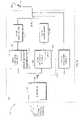
- FIG. 1is a block diagram of a system in which a portable device such a laptop computer is making use of a protocol converter according to the invention to connect to a computer network over a wireless cellular link.
- FIG. 2is a diagram depicting how network layer data frames are divided among multiple physical links or channels.
- FIG. 3is a more detailed diagram showing how network layer frames are divided into subframes by a protocol converter located at a sender.
- FIG. 4is a continuation of the diagram of FIG. 3 .
- FIG. 5is a schematic diagram of a short range, high speed wireless LAN overlapping with a longer range, lower speed wireless communication network.
- FIG. 6is a high-level block diagram of a subscriber unit of the present invention.
- FIG. 1is a block diagram of a system 10 for implementing high speed data communication over a cellular link according to the invention.
- the system 10consists of a remote or subscriber unit 20 , multiple bi-directional communication links 30 , and a local or service provider unit 40 .
- the subscriber unit 20connects to terminal equipment 22 such as a portable or laptop computer, hand held Personal Digital Assistant (PDA) or the like, via a computer interface 24 such as a modem.
- terminal equipment 22such as a portable or laptop computer, hand held Personal Digital Assistant (PDA) or the like
- PDAPersonal Digital Assistant
- the interface 24in turn provides data to a protocol converter 25 , which in turn provides data to a multichannel digital transceiver 26 and antenna 27 .
- the interface 24receives data from the computer 20 , and together with appropriate hardware and/or software, converts it to a format suitable for transmission such as in accordance with known communication standards.
- the interface 24may convert data signals from the terminal equipment 22 to a wireline physical layer protocol format such as specified by the Integrated Services Digital Network (ISDN) standard at rates of 128 kbps, or the Kflex standard at rates of 56.6 kbps.
- ISDNIntegrated Services Digital Network
- the data provided by the interface 24is preferably formatted in a manner consistent with suitable network communication protocols such as TCP/IP to permit the terminal equipment 22 to connect to other computers over networks Such as the Internet.
- TCP/IPnetwork communication protocols
- This description of the interface 24 and protocolsis exemplary only and it should be understood that other protocols can be used.
- the protocol converter 25implements an intermediate protocol layer suitable for converting the data provided by the interface 24 to a format appropriate for the multichannel transceiver 26 according to the invention, and as is described in greater detail below.
- the multichannel digital transceiver 26provides access to one or more physical communication links such as the illustrated radio channels 30 .
- the physical linksare preferably known wireless communication air interfaces using digital modulation techniques such as Code Division Multiple Access (CDMA) standard specified by IS-95. It should be understood that other wireless communication protocols and other types of links 30 may also be used to advantage with the invention.
- CDMACode Division Multiple Access
- the channels 30represent one or more relatively slower communication channels, such as operating at a 9.6 kbps rate typical of voice grade communication. These communications channels may be provided by a single wide bandwidth CDMA carrier such as having a 1.25 MegaHertz bandwidth, and then providing the individual channels with unique orthogonal CDMA codes. Alternatively, the multiple channels 30 may be provided by single channel communication media such as provided by other wireless communication protocols. However, what is important is that the net effect is that the channels 30 represent multiple communication channels that may be adversely effected by significant bit error rates that are unique to each link 30 .
- erroras described herein is a bit error perceived at the higher layer Such as the network layer.
- the inventiononly strives to improve the system level bit error rate, and does not attempt to guarantee absolute data integrity.
- the service provider equipment 40may for example be implemented at a wireless Internet Service Provider (ISP) 40 - 1 .
- the equipmentincludes an antenna 42 - 1 , a multichannel transceiver 44 - 1 , a protocol converter 46 - 1 , and other equipment 48 - 1 such as modems, interfaces, routers, and the like which are needed for the ISP to provide connections to the Internet 49 - 1 .
- the multichannel transceiver 44 - 1provides functions analagous to the multichannel transceiver 26 of the subscriber unit, but in an inverse fashion.
- the same is true of the protocol converter 46 - 1that is, it provides inverse functionality to the protocol converter 25 in the subscriber unit 20 .
- the ISP 40 - 1accepts data from the protocol converter 46 - 1 in the TCP/IP frame format and then communicates such data to the Internet 49 - 1 .
- the configuration of the remaining ISP equipment 48 - 1may take any number of forms such as a local area networks, multiple dial up connections, TI carrier connection equipment, or other high speed communication links to the Internet 49 - 1 .
- the provider 40may function as a radio base station in a cellular telephone system to permit a dial-up connection between the terminal equipment 22 and a server 49 - 2 .
- the base station 40 - 2includes an antenna 42 - 2 , multichannel transceiver 44 - 2 , and protocol converter 46 - 2 providing one or more connections to a public switched telephone network (PSTN) 48 - 2 , and ultimately to the server 49 - 2 .
- PSTNpublic switched telephone network
- the protocol converters 25 and 46can be thought of as an intermediate layer within the context of the Open System Interconnect (OSI) model for communication.
- the protocol converterprovides a bandwidth management functionality 29 implemented between a physical layer such as that provided by the CDMA protocol in use with the multichannel transceivers 26 and a network layer protocol such as TCP/IP providing connections between the terminal equipment 22 and the Internet 49 - 1 or server 49 - 2 .
- the bandwidth management functionality 29preferably provides a number of functions in order to keep both the physical layer and network layer connections properly maintained over multiple communication links 30 .
- certain physical layer connectionsmay expect to receive a continuous stream of synchronous data bits regardless of whether terminal equipment at either end actually has data to transmit.
- Such functionsmay also include rate adaption, bonding of multiple channels on the links, spoofing, radio channel setup and takedown.
- the present inventionis more particularly concerned with the technique used by the protocol converters 25 and 46 for adjusting the frame size of individual channels used over each of the multiple links 30 in order to improve the effective throughput rate between a sender and a receiver in a bit error rate prone environment. It should be understood in the following discussion that the connections discussed herein are bidirectional, and that a sender may either be the subscriber unit 22 or the provider unit 40 .
- the frame 60 as received at the receiver endmust be identical to the frame 50 originating at the sender. This is despite the fact that multiple channels are used with much higher bit error rates, with the received frame 60 being transmitted reliably with a bit error rate of 10 ⁇ 6 or better as is typically required in TCP/IP or other network layer protocols.
- the present inventionoptimizes the effective data throughput such that the received frames 60 are not affected by the experienced bit error rate performance of network layer connections.
- the individual channels 30 - 1 , 30 - 2 . . . 30 -Nmay experience different bit error rate levels both over time and in an average sense.
- each of the channels 30may operate quite similarly, given the statistical nature of errors, identical behavior of all of the channels 30 is not assumed.
- a specific channel 30 - 3may receive severe interference from another connection in a neighboring cell, and be capable of providing only a 10 ⁇ 3 whereby other channels 30 may experience very little interference.
- the inventionalso preferably optimizes the parameters of each channel 30 separately. Otherwise, a relatively good channel 30 - 1 might suffer down speed procedures required to accommodate a weaker channel 30 - 3 .
- the number of channels 30 that may be needed to carry a single data stream such as a rate of 128 kbps at a given point in timemay be relatively large. For example, up to 20 channels 30 may be assigned at a particular time in order to accommodate a desired data transfer rate. Therefore, the probability of significantly different characteristics in any given one of the channels 30 is high.
- the input frame 50 as received from the network layeris relatively large, such as for example 1480 bits long, in the case of a TCP/IP frame.
- the input frame 50is first divided into a set of smaller pieces 54 - 1 , 54 - 2 .
- the size of the individual pieces 54are chosen based upon the optimum subframe size for each of the channels 30 available. For example a bandwidth management function may make only a certain number of channels 30 available at any time. A subset of the available channels 30 is selected, and then the optimum number of bits for each subframe intended to be transmitted over respective one of the channels, is then chosen.
- a given frame 54 - 1may be divided into pieces associated with four channels. At a later time, there may be nine channels 30 available for a frame, with different optimum subframe sizes for the piece 54 - 2 .
- Each of the subframes 56consists of a position identifier 58 a , a data portion 58 b , and a trailer typically in the form of an integrity checksum such as a cyclic redundancy check (CRC) 58 c .
- the position identifier 58 a for each subframeindicates the position within the associated larger frame 50 .
- the subframes 56are then further prepared for transmission on each channel 30 . This may be done by adding a sequence number related to each channel at the beginning of each subframe 56 .
- the subframe 56is then transmitted over the associated channel 30 .
- FIG. 4illustrates the operations performed at the receive side.
- the subframes 56are first received on the individual channels 30 .
- a subframe 56is discarded as received if the CRC portion 58 c is not correct.
- sequence numbers 58 d of the remaining frames 56are then stripped off and used to determine whether any subframes 56 are missing. Missing subframes 56 can be detected by comparing the received sequence numbers 58 d . If a sequence number is missing, it is assumed that the associated subframe 56 was not received properly. It should be understood that appropriate buffering of data and subframes 56 is typically required in order to properly receive the subframes 56 and determine if there are any missing sequence numbers depending upon the transmission rates, number of channels 30 and propagation delays in effect.
- the position number 58 ais used to arrange the data from the subframes 56 in the proper order to construct the output received frame 60 .
- the sender and receiverknow the ratio of the number of subframes received with errors to the number of frames received without errors. Also, the receiver and sender know the average subframe length for each channel. The optimum subframe size can thus be determined for each channel from these parameters as is described more fully in U.S. Pat. No. 6,236,647 filed on Feb. 24, 1998, entitled “Dynamic Frame Size Adjustment and Selective Reject On a Multi-Link Channel to Improve Effective Throughput and Bit Error Rate,” incorporated herein by reference in its entirety, and assigned to Tantivy Communications Corp., the assignee of the present application.
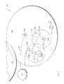
- FIG. 5illustrates a short range, high speed wireless LAN (W-LAN) overlapping with a longer range, lower speed wireless cellular communication network (“long range network”).
- W-LANwireless LAN
- long range networka longer range, lower speed wireless cellular communication network
- the longer range, lower speed systemwhich may be a digital cellullar mobile telephone system
- the range or coverage for each cell 601 , 603is on the order of, for example, greater than one mile radius.
- a cellular base station 605transmits and receives data through its antenna 171 to mobile units located within its associated cell 601 .
- the base station 605is connected to a public network 619 such as the public switched telephone network (PSTN) or preferably a point of presence (POP) or other data connection 621 to the Internet.
- PSTNpublic switched telephone network
- POPpoint of presence
- W-LANwireless local area network
- Several terminals or computers 609are connected directly to the W-LAN 607 , including a gateway 609 A which is also connected to the public network 619 via any well-known means 621 .
- two wireless LAN hubs 611 A, 611 Bare connected to the LAN 607 .
- Each wireless LAN hub 611has a region of coverage 613 A, 613 B; the coverage area of the two hubs 611 A, 611 B may overlap as shown in FIG. 5 .
- the regions of coverage 613 A, 613 Bare generally of the order of tens or hundreds of feet, which is significantly smaller than the cells 601 , 603 associated with the long range network. In this respect, it is particularly important to note that FIG. 5 is not drawn to scale.
- the first terminal 615is within range 613 A of a wireless LAN base station 611
- the second terminal 617is outside the range of either wireless LAN base station 611 A, 611 B but within the range 601 of the long range network base station 605 .
- the short range wireless LAN 613 A or 613 Bis faster and less expensive as compared to the long range network, it is desirable to communicate using the short range path, i.e., the W-LAN protocol, rather than the more costly long range network, when a user's computer terminal 615 is within range of a W-LAN base station 611 , i.e., within the region of coverage 613 A, 613 B.
- the short range pathi.e., the W-LAN protocol
- a terminalsuch as terminal 617 , which is not within range of a wireless LAN base station 611 , automatically communicate through the long range network's base station 605 .
- a terminalsuch as 615 or 617 detects the presence or availability of a wireless LAN hub 611 A or 611 B, such as an IEEE 802.11-compliant W-LAN hub.
- IEEE 802.11specifies that a beacon frame should be transmitted at regular intervals.
- a terminal 615 , 617can detect the beacon frame by waiting a minimum period of time equal to the beacon interval. See, for example, Geier, J., Wireless LANs , pages 137 and 149, (Macmillan Technical Publishing, 1999), incorporated herein by reference, which describes how a W-LAN beacon signal is formatted.
- a terminalsuch as 615 may actively transmit a probe request frame.
- a wireless LAN base station 611 receiving such a probe request framewill respond with a probe response frame. Receipt of the probe response frame by the terminal 615 indicates accessibility of the wireless LAN, and the terminal 615 will use the wireless LAN and bypass the long range network.
- the terminalassumes that the wireless LAN base stations 611 are not accessible and instead communicates with the long range base station 605 using the long range network protocol rather than IEEE 802.11 protocol.
- Yet another alternativeis simply to listen for activity on the wireless LAN 611 . If no activity is heard, the terminal 615 , 617 assumes that the LAN is not accessible, and uses the long range communication system.
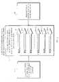
- FIG. 6shows a terminal 615 which includes a subscriber unit 101 incorporating the features of the present invention.
- a user at this terminal 615desires to communicate with a second site using a portable computer 110 , PDA or other similar device.
- the computer 110is connected to the subscriber unit 101 .
- the subscriber unit 101may be a PCMCIA card which plugs into a PCMCIA slot, or it may connect to the computer 110 with a modem cable.
- the subscriber unit 101itself preferably consists of an interface 120 , a CDMA protocol converter 130 that performs various functions including spoofing 132 and bandwidth management 134 as described earlier, a CDMA transceiver 140 , a W-LAN protocol converter 230 , a W-LAN transceiver 240 , a W-LAN detection circuit 201 , path selection switches 211 A, 211 B, and a subscriber unit antenna 150 .
- the various components of the subscriber unit 101may be realized in discrete devices or as an integrated unit.
- an existing conventional computer interface 120such as the PCMCIA, ISA bus, PCI bus, or any other computer interface may be used together with existing transceivers 140 , 240 .
- the unique functionsare provided entirely by the protocol converters 130 , 230 which may be sold as separate devices, the W-LAN detection circuit 201 and the mode selection switches 211 A, 211 B.
- the interface 120 , protocol converters 130 , 233 , and transceivers 140 , 240may be integrated as a complete unit and sold as a single subscriber unit device 101 .
- Other types of interface connectionssuch as Ethernet, ISDN, or still other data connections may be used to connect the computing device 110 to the protocol converter 130 .
- the CDMA protocol converter 130performs spoofing 132 and basic bandwidth management 134 functions.
- spoofing 132consists of insuring that the subscriber unit 101 appears, to the terminal equipment 110 , to be connected to the public network 619 ( FIG. 5 ) on the other side of the base station 605 at all times.
- the bandwidth management function 134is responsible for allocating and deallocating CDMA radio channels 160 as required.
- Bandwidth management 134also includes the dynamic management of the bandwidth allocated to a given session by dynamically assigning sub-portions of the CDMA radio channels 160 in a manner using a protocol such as that described previously.
- the CDMA transceiver 140accepts the data from the protocol converter 130 and reformats this data in appropriate form for transmission through the subscriber unit antenna 150 over the radio link 160 .
- the CDMA transceiver 140may operate over only a single 1.25 MHZ radio frequency channel or, alternatively, may be tunable over multiple allocatable radio frequency channels.
- CDMA signal transmissionsare then received and processed by the base station equipment 605 ( FIG. 5 ).
- the base station 605then couples the demodulated radio signals to, for example, the public network 619 in a manner which is well known in the art.
- the base station 605may communicate with the public network 619 over any number of different efficient communication protocols such as primary rate, ISDN, or other LAPD based protocols such as IS-634 or V5.2.
- data signalstravel bidirectionally across the CDMA radio channels 160 .
- data signals received from the public network 619are coupled to the portable computer 110 in a forward link direction
- data signals originating at the portable computer 110are coupled to the public network 619 in a so-called reverse link direction.
- the spoofing function 132involves having the CDMA transceiver 140 loop back synchronous data bits to spoof the terminal equipment 110 into believing that a sufficiently wide wireless communication link 160 is continuously available.
- wireless bandwidthis allocated only when there is actual data present from the terminal equipment to the CDMA transceiver 140 . Therefore, the network layer need not allocate the assigned wireless bandwidth for the entirety of the communications session. That is, when data is not being presented upon the terminal equipment to the network equipment, the bandwidth management function 134 deallocates initially assigned radio channel bandwidth 160 and makes it available for another transceiver and another subscriber unit 101 .
- W-LAN detection circuit 201detects the presence or availability of a W-LAN base station 611 using, for example, one of the techniques previously discussed. If no W-LAN base station is detected, switches 211 A and 211 B are controlled by the detection circuit 201 such that the CDMA protocol converter 130 is switched in along with the CDMA transceiver 140 .
- switches 211 A and 211 Bare switched to the position shown to utilize the W-LAN protocol converter 230 and transceiver 240 , which are preferably IEEE 802.11-compliant.
- the path switches 211 A, 211 Bmay be implemented in software or hardware, or a combination of hardware and software. Other functions may also be implemented in hardware and/or software which may further be shared by the W-LAN and CDMA sections where appropriate.
- the long-range, low-speed CDMA pathcould be selected after failure to communicate over the short-range, high speed path for any reason, for example, the inability to successfully complete a communication after some predetermined time period.
Landscapes
- Engineering & Computer Science (AREA)
- Computer Networks & Wireless Communication (AREA)
- Signal Processing (AREA)
- Computer Security & Cryptography (AREA)
- Mobile Radio Communication Systems (AREA)
Abstract
Description
Claims (51)
Priority Applications (13)
| Application Number | Priority Date | Filing Date | Title |
|---|---|---|---|
| US10/341,528US7024222B2 (en) | 1999-09-21 | 2003-01-13 | Dual mode unit for short range, high rate and long range, lower rate data communications |
| TW093100657ATW200415927A (en) | 2003-01-13 | 2004-01-12 | Dual mode unit for short range, high rate and long range, lower rate data communications |
| PCT/US2004/000891WO2004064308A2 (en) | 2003-01-13 | 2004-01-13 | Dual mode unit for short range, high rate and long range, lower rate data communications |
| EP04701813AEP1590977A4 (en) | 2003-01-13 | 2004-01-13 | Dual mode unit for short range, high rate and long range, lower rate data communications |
| KR1020077010367AKR20070064659A (en) | 2003-01-13 | 2004-01-13 | Dual mode unit for short range high speed data communication and long range low speed data communication |
| JP2006500945AJP2006516376A (en) | 2003-01-13 | 2004-01-13 | Dual mode unit for short range high speed and long range low speed data communication |
| KR1020057013006AKR20050092042A (en) | 2003-01-13 | 2004-01-13 | Dual mode unit for short range, high rate and long range, lower rate data communications |
| NO20053590ANO20053590L (en) | 2003-01-13 | 2005-07-25 | Dual mode device for short distance, high rate and long distance, lower data rate communication. |
| US11/326,809US7616970B2 (en) | 1999-09-21 | 2006-01-06 | Dual mode unit for short range, high rate and long range, lower rate data communications |
| US12/615,098US8380244B2 (en) | 1999-09-21 | 2009-11-09 | Dual mode unit for short range, high rate and long range, lower rate data communications |
| US13/753,149US9420632B2 (en) | 1999-09-21 | 2013-01-29 | Subscriber unit for managing dual wireless communication links |
| US14/599,028US9408253B2 (en) | 1999-09-21 | 2015-01-16 | Subscriber unit for managing dual wireless communication links |
| US15/234,198US20160353508A1 (en) | 1999-09-21 | 2016-08-11 | Subscriber unit for managing dual wireless communication links |
Applications Claiming Priority (2)
| Application Number | Priority Date | Filing Date | Title |
|---|---|---|---|
| US09/400,136US6526034B1 (en) | 1999-09-21 | 1999-09-21 | Dual mode subscriber unit for short range, high rate and long range, lower rate data communications |
| US10/341,528US7024222B2 (en) | 1999-09-21 | 2003-01-13 | Dual mode unit for short range, high rate and long range, lower rate data communications |
Related Parent Applications (2)
| Application Number | Title | Priority Date | Filing Date |
|---|---|---|---|
| US09/400,136Continuation-In-PartUS6526034B1 (en) | 1999-09-21 | 1999-09-21 | Dual mode subscriber unit for short range, high rate and long range, lower rate data communications |
| US09/400,136ContinuationUS6526034B1 (en) | 1999-09-21 | 1999-09-21 | Dual mode subscriber unit for short range, high rate and long range, lower rate data communications |
Related Child Applications (2)
| Application Number | Title | Priority Date | Filing Date |
|---|---|---|---|
| US10/358,082ContinuationUS7013162B2 (en) | 1999-09-21 | 2003-02-03 | Dual mode unit for short range, high rate and long range, lower rate data communications |
| US10/358,082Continuation-In-PartUS7013162B2 (en) | 1999-09-21 | 2003-02-03 | Dual mode unit for short range, high rate and long range, lower rate data communications |
Publications (2)
| Publication Number | Publication Date |
|---|---|
| US20040029612A1 US20040029612A1 (en) | 2004-02-12 |
| US7024222B2true US7024222B2 (en) | 2006-04-04 |
Family
ID=32711530
Family Applications (1)
| Application Number | Title | Priority Date | Filing Date |
|---|---|---|---|
| US10/341,528Expired - LifetimeUS7024222B2 (en) | 1999-09-21 | 2003-01-13 | Dual mode unit for short range, high rate and long range, lower rate data communications |
Country Status (7)
| Country | Link |
|---|---|
| US (1) | US7024222B2 (en) |
| EP (1) | EP1590977A4 (en) |
| JP (1) | JP2006516376A (en) |
| KR (2) | KR20070064659A (en) |
| NO (1) | NO20053590L (en) |
| TW (1) | TW200415927A (en) |
| WO (1) | WO2004064308A2 (en) |
Cited By (12)
| Publication number | Priority date | Publication date | Assignee | Title |
|---|---|---|---|---|
| US20040203685A1 (en)* | 2002-11-26 | 2004-10-14 | Woodward Ernest E. | Portable communication device having a service discovery mechanism and method therefor |
| US20060256803A1 (en)* | 2004-01-09 | 2006-11-16 | Tsuneo Nakata | Communication method |
| US20070171883A1 (en)* | 2000-03-17 | 2007-07-26 | Symbol Technologies, Inc. | Rf port for multiple wireless local area networks |
| US20070268876A1 (en)* | 2006-05-18 | 2007-11-22 | Daniel Yellin | System, apparatus and method to route radio frequency signals |
| US7321599B1 (en)* | 2002-07-30 | 2008-01-22 | Otc Wireless, Inc. | Wired protocol to wireless protocol converter |
| EP1965571A1 (en) | 2007-03-02 | 2008-09-03 | Research In Motion Limited | Service status display on a handheld communications device |
| US20100166020A1 (en)* | 2008-12-31 | 2010-07-01 | Sasha Rantsevitch | Mlppp sequence number synchronization between the active and standby transmitters |
| US7852837B1 (en)* | 2003-12-24 | 2010-12-14 | At&T Intellectual Property Ii, L.P. | Wi-Fi/BPL dual mode repeaters for power line networks |
| US20110199186A1 (en)* | 2010-02-18 | 2011-08-18 | Samsung Electronics Co., Ltd | Passive wireless memory device |
| US8687610B2 (en) | 1998-01-16 | 2014-04-01 | Symbol Technologies, Inc. | Infrastructure for wireless LANS |
| US8699474B2 (en) | 2000-03-17 | 2014-04-15 | Symbol Technologies, Inc. | System with a cell controller adapted to perform a management function |
| US10945289B2 (en) | 2019-02-12 | 2021-03-09 | Qts Holdings, Llc | System for collision avoidance in transfer of network packets |
Families Citing this family (26)
| Publication number | Priority date | Publication date | Assignee | Title |
|---|---|---|---|---|
| US6526034B1 (en) | 1999-09-21 | 2003-02-25 | Tantivy Communications, Inc. | Dual mode subscriber unit for short range, high rate and long range, lower rate data communications |
| US7400587B2 (en)* | 2002-11-13 | 2008-07-15 | Edgewater Computer Systems, Inc. | Optimum frame fragmentation method for communication over error prone channels |
| CN101304355A (en)* | 2003-05-28 | 2008-11-12 | 赛宝技术公司 | Backup cell controller |
| JP2007504786A (en)* | 2003-05-28 | 2007-03-01 | シンボル テクノロジーズ, インコーポレイテッド | Improved wireless network cell controller |
| US20040264413A1 (en)* | 2003-06-26 | 2004-12-30 | Oren Kaidar | Device, system and method for channel scanning |
| US7266101B2 (en)* | 2003-06-30 | 2007-09-04 | Motorola, Inc. | Fast handover through proactive registration |
| WO2005083944A1 (en)* | 2004-02-26 | 2005-09-09 | Quorum Systems, Inc. | Using collision avoidance to menimize wireless lan interference in a multi-mode wireless communication device |
| US7966012B2 (en) | 2004-09-09 | 2011-06-21 | Parkervision, Inc. | Wireless protocol converter |
| JP4631401B2 (en)* | 2004-11-10 | 2011-02-16 | 日本電気株式会社 | Presence update system and method, and mobile communication terminal used therefor |
| US7801555B2 (en) | 2005-07-22 | 2010-09-21 | Qualcomm Incorporated | User operation of a wireless device capable of communicating with multiple networks |
| US7164285B1 (en)* | 2005-08-12 | 2007-01-16 | Stratex Networks, Inc. | Directional power detection by quadrature sampling |
| US20070082697A1 (en)* | 2005-10-07 | 2007-04-12 | Research In Motion Limited | System and method of handset configuration between cellular and private wireless network modes |
| US7562167B2 (en)* | 2005-11-14 | 2009-07-14 | Deere & Company | Managing heterogeneous data streams for remote access |
| JP2008079039A (en)* | 2006-09-21 | 2008-04-03 | Matsushita Electric Ind Co Ltd | Game portable terminal device and information processing terminal |
| US9942883B2 (en) | 2006-11-13 | 2018-04-10 | Samsung Electronics Co., Ltd. | Method and apparatus for allocating bandwidth of wireless network where both wide-band and narrow-band signals are transmitted, and method and apparatus for transmitting and receiving data on the network |
| KR100878538B1 (en)* | 2006-11-13 | 2009-01-13 | 삼성전자주식회사 | Bandwidth allocation method and device, data transmission and reception method and device in wireless network |
| US8054743B2 (en)* | 2007-08-20 | 2011-11-08 | Ntt Docomo, Inc. | Mobile communication terminal, communication apparatus, mobile communication method, and communication method |
| JP5010573B2 (en)* | 2008-11-27 | 2012-08-29 | 株式会社東芝 | Wireless device and control method thereof |
| US8838706B2 (en)* | 2010-06-24 | 2014-09-16 | Microsoft Corporation | WiFi proximity messaging |
| KR20130053696A (en)* | 2011-11-16 | 2013-05-24 | 삼성전자주식회사 | Device and method for communicating a data of wireless terminal |
| US9622127B2 (en)* | 2012-11-30 | 2017-04-11 | Tejas Networks Limited | Method and system for wireless communication |
| KR102374409B1 (en)* | 2015-10-27 | 2022-03-14 | 에스케이플래닛 주식회사 | APPARATUS, METHOD and RECODING MEDIUM for MANAGING WIRELESS MESH NETWORK |
| US10367836B2 (en)* | 2015-10-27 | 2019-07-30 | Sk Planet Co., Ltd. | Method and apparatus for detecting abnormal state of beacon device in wireless mesh network and recording medium storing computer program for executing the method |
| US11849453B2 (en)* | 2016-04-12 | 2023-12-19 | Marvell Asia Pte Ltd | Reporting bandwidth capability of a bandwidth-limited communication device |
| CN116600372A (en)* | 2016-11-03 | 2023-08-15 | 交互数字专利控股公司 | Method for efficient power saving for waking up a radio |
| US11418923B2 (en) | 2018-11-09 | 2022-08-16 | Amosense Co., Ltd | Asset tracking communication device |
Citations (15)
| Publication number | Priority date | Publication date | Assignee | Title |
|---|---|---|---|---|
| US5020092A (en) | 1989-06-23 | 1991-05-28 | Motorola, Inc. | Dual-bandwidth cellular telephone |
| US5020093A (en) | 1989-06-23 | 1991-05-28 | Motorola, Inc. | Cellular telephone operable on different cellular telephone systems |
| US5228074A (en) | 1991-04-15 | 1993-07-13 | Sony Corporation | Dual mode cellular telephone apparatus |
| US5406643A (en)* | 1993-02-11 | 1995-04-11 | Motorola, Inc. | Method and apparatus for selecting between a plurality of communication paths |
| US5504803A (en) | 1991-11-25 | 1996-04-02 | Matsushita Electric Industrial Co., Ltd. | Method for automatic mode selection for a dual-mode telephone handset for use in a cellular mobile telephone system and in a wireless telephone system |
| US5657317A (en) | 1990-01-18 | 1997-08-12 | Norand Corporation | Hierarchical communication system using premises, peripheral and vehicular local area networking |
| US5696903A (en) | 1993-05-11 | 1997-12-09 | Norand Corporation | Hierarchical communications system using microlink, data rate switching, frequency hopping and vehicular local area networking |
| US5796727A (en) | 1993-04-30 | 1998-08-18 | International Business Machines Corporation | Wide-area wireless lan access |
| US5815811A (en) | 1989-06-29 | 1998-09-29 | Symbol Technologies, Inc. | Preemptive roaming in a cellular local area wireless network |
| US5842122A (en) | 1992-02-06 | 1998-11-24 | Motorola, Inc. | Apparatus and method for alternative radiotelephone system selection |
| US5845211A (en) | 1995-01-13 | 1998-12-01 | Bell South Corporation | Wireless digital network |
| WO1998059523A2 (en) | 1997-06-20 | 1998-12-30 | Tantivy Communications, Inc. | Dynamic bandwidth allocation to transmit a wireless protocol across a code division multiple access (cdma) radio link |
| WO1999038083A1 (en) | 1998-01-21 | 1999-07-29 | Motorola Inc. | Messaging system for conditionally selecting a network |
| US6236642B1 (en) | 1997-07-17 | 2001-05-22 | Siemens Information And Communication Networks, Inc. | Apparatus and method for network resource preservation |
| US6526034B1 (en)* | 1999-09-21 | 2003-02-25 | Tantivy Communications, Inc. | Dual mode subscriber unit for short range, high rate and long range, lower rate data communications |
- 2003
- 2003-01-13USUS10/341,528patent/US7024222B2/ennot_activeExpired - Lifetime
- 2004
- 2004-01-12TWTW093100657Apatent/TW200415927A/enunknown
- 2004-01-13EPEP04701813Apatent/EP1590977A4/ennot_activeWithdrawn
- 2004-01-13KRKR1020077010367Apatent/KR20070064659A/ennot_activeWithdrawn
- 2004-01-13JPJP2006500945Apatent/JP2006516376A/ennot_activeWithdrawn
- 2004-01-13KRKR1020057013006Apatent/KR20050092042A/ennot_activeWithdrawn
- 2004-01-13WOPCT/US2004/000891patent/WO2004064308A2/enactiveApplication Filing
- 2005
- 2005-07-25NONO20053590Apatent/NO20053590L/ennot_activeApplication Discontinuation
Patent Citations (17)
| Publication number | Priority date | Publication date | Assignee | Title |
|---|---|---|---|---|
| US5020093A (en) | 1989-06-23 | 1991-05-28 | Motorola, Inc. | Cellular telephone operable on different cellular telephone systems |
| US5020092A (en) | 1989-06-23 | 1991-05-28 | Motorola, Inc. | Dual-bandwidth cellular telephone |
| US5815811A (en) | 1989-06-29 | 1998-09-29 | Symbol Technologies, Inc. | Preemptive roaming in a cellular local area wireless network |
| US5657317A (en) | 1990-01-18 | 1997-08-12 | Norand Corporation | Hierarchical communication system using premises, peripheral and vehicular local area networking |
| US5228074A (en) | 1991-04-15 | 1993-07-13 | Sony Corporation | Dual mode cellular telephone apparatus |
| US5504803A (en) | 1991-11-25 | 1996-04-02 | Matsushita Electric Industrial Co., Ltd. | Method for automatic mode selection for a dual-mode telephone handset for use in a cellular mobile telephone system and in a wireless telephone system |
| US5842122A (en) | 1992-02-06 | 1998-11-24 | Motorola, Inc. | Apparatus and method for alternative radiotelephone system selection |
| US5406643A (en)* | 1993-02-11 | 1995-04-11 | Motorola, Inc. | Method and apparatus for selecting between a plurality of communication paths |
| US5796727A (en) | 1993-04-30 | 1998-08-18 | International Business Machines Corporation | Wide-area wireless lan access |
| US5696903A (en) | 1993-05-11 | 1997-12-09 | Norand Corporation | Hierarchical communications system using microlink, data rate switching, frequency hopping and vehicular local area networking |
| US5845211A (en) | 1995-01-13 | 1998-12-01 | Bell South Corporation | Wireless digital network |
| WO1998059523A2 (en) | 1997-06-20 | 1998-12-30 | Tantivy Communications, Inc. | Dynamic bandwidth allocation to transmit a wireless protocol across a code division multiple access (cdma) radio link |
| US6236642B1 (en) | 1997-07-17 | 2001-05-22 | Siemens Information And Communication Networks, Inc. | Apparatus and method for network resource preservation |
| WO1999038083A1 (en) | 1998-01-21 | 1999-07-29 | Motorola Inc. | Messaging system for conditionally selecting a network |
| US6084866A (en) | 1998-01-21 | 2000-07-04 | Motorola, Inc. | Method and apparatus in a wireless messaging system for minimizing unnecessary communications with coverage zones of differing size and differing bandwidth capacity when entered by a mobile subscriber unit |
| US6526034B1 (en)* | 1999-09-21 | 2003-02-25 | Tantivy Communications, Inc. | Dual mode subscriber unit for short range, high rate and long range, lower rate data communications |
| US20040018854A1 (en)* | 1999-09-21 | 2004-01-29 | Tantivy Communications, Inc. | Dual mode unit for short range, high rate and long range, lower rate data communications |
Non-Patent Citations (4)
| Title |
|---|
| "IEEE 802.11 Technical Tutorial," pp. 1-18, downloaded from http://www.breezecom.com, No Date Listed. |
| "IEEE 802.11 Wireless LAN Standard," The MAC Layer, pp. 1-2, downloaded Jul. 15, 1999 from http://www.wlana.com/intro/standard/mac.html. |
| Grube, G., et al., "In-Building Wireless Coverage Using a Second Mode", Motorola XP 000594558, pp. 66-68 (May 1996). |
| Melanchuk et al., "CDPD and Emerging Digital Cellular Systems," XP000628458, pp. 2-8 (1996), No Month Listed. |
Cited By (29)
| Publication number | Priority date | Publication date | Assignee | Title |
|---|---|---|---|---|
| US8687610B2 (en) | 1998-01-16 | 2014-04-01 | Symbol Technologies, Inc. | Infrastructure for wireless LANS |
| US8699474B2 (en) | 2000-03-17 | 2014-04-15 | Symbol Technologies, Inc. | System with a cell controller adapted to perform a management function |
| US20070171883A1 (en)* | 2000-03-17 | 2007-07-26 | Symbol Technologies, Inc. | Rf port for multiple wireless local area networks |
| US20070177435A1 (en)* | 2000-03-17 | 2007-08-02 | Symbol Technologies, Inc. | System for multiple wireless local area networks |
| US8498278B2 (en) | 2000-03-17 | 2013-07-30 | Symbol Technologies, Inc. | System for multiple wireless local area networks |
| US8050240B2 (en) | 2000-03-17 | 2011-11-01 | Symbol Technologies, Inc. | Multiple wireless local area networks occupying overlapping physical spaces |
| US8391256B2 (en) | 2000-03-17 | 2013-03-05 | Symbol Technologies, Inc. | RF port for multiple wireless local area networks |
| US8699473B2 (en) | 2000-03-17 | 2014-04-15 | Symbol Technologies, Inc. | Cell controller for multiple wireless local area networks |
| US8027320B2 (en) | 2000-03-17 | 2011-09-27 | Symbol Technologies, Inc. | Wireless local area networks |
| US7321599B1 (en)* | 2002-07-30 | 2008-01-22 | Otc Wireless, Inc. | Wired protocol to wireless protocol converter |
| US20040203685A1 (en)* | 2002-11-26 | 2004-10-14 | Woodward Ernest E. | Portable communication device having a service discovery mechanism and method therefor |
| US10728127B2 (en) | 2003-12-24 | 2020-07-28 | At&T Intellectual Property Ii, L.P. | Wi-Fi/BPL dual mode repeaters for power line networks |
| US8780901B2 (en)* | 2003-12-24 | 2014-07-15 | At&T Intellectual Property Ii, L.P. | Wi-Fi/BPL dual mode repeaters for power line networks |
| US20110058614A1 (en)* | 2003-12-24 | 2011-03-10 | At&T Intellectual Property Ii, L.P. | Wi-Fi/BPL Dual Mode Repeaters for Power Line Networks |
| US7852837B1 (en)* | 2003-12-24 | 2010-12-14 | At&T Intellectual Property Ii, L.P. | Wi-Fi/BPL dual mode repeaters for power line networks |
| US10193777B2 (en) | 2003-12-24 | 2019-01-29 | At&T Intellectual Property Ii, L.P. | Wi-Fi/BPL dual mode repeaters for power line networks |
| US20060256803A1 (en)* | 2004-01-09 | 2006-11-16 | Tsuneo Nakata | Communication method |
| US7826866B2 (en)* | 2006-05-18 | 2010-11-02 | Intel Corporation | System, apparatus and method to route radio frequency signals |
| US20070268876A1 (en)* | 2006-05-18 | 2007-11-22 | Daniel Yellin | System, apparatus and method to route radio frequency signals |
| US8903392B2 (en) | 2007-03-02 | 2014-12-02 | Blackberry Limited | Service status display on a handheld communication device |
| US8306534B2 (en) | 2007-03-02 | 2012-11-06 | Research In Motion Limited | Service status display on a handheld communication device |
| US20080214191A1 (en)* | 2007-03-02 | 2008-09-04 | David Yach | Service status display on a handheld communication device |
| EP1965571A1 (en) | 2007-03-02 | 2008-09-03 | Research In Motion Limited | Service status display on a handheld communications device |
| US7929423B2 (en)* | 2008-12-31 | 2011-04-19 | Alcatel Lucent | MLPPP sequence number synchronization between the active and standby transmitters |
| US20100166020A1 (en)* | 2008-12-31 | 2010-07-01 | Sasha Rantsevitch | Mlppp sequence number synchronization between the active and standby transmitters |
| US20110199186A1 (en)* | 2010-02-18 | 2011-08-18 | Samsung Electronics Co., Ltd | Passive wireless memory device |
| US8704640B2 (en)* | 2010-02-18 | 2014-04-22 | Samsung Electronics Co., Ltd | Passive wireless memory device |
| US10945289B2 (en) | 2019-02-12 | 2021-03-09 | Qts Holdings, Llc | System for collision avoidance in transfer of network packets |
| US11044753B2 (en) | 2019-02-12 | 2021-06-22 | Qts Holdings, Llc | Method for collision avoidance in transfer of network packets |
Also Published As
| Publication number | Publication date |
|---|---|
| US20040029612A1 (en) | 2004-02-12 |
| NO20053590D0 (en) | 2005-07-25 |
| JP2006516376A (en) | 2006-06-29 |
| EP1590977A4 (en) | 2011-02-09 |
| NO20053590L (en) | 2005-07-25 |
| KR20070064659A (en) | 2007-06-21 |
| KR20050092042A (en) | 2005-09-16 |
| WO2004064308B1 (en) | 2005-07-14 |
| WO2004064308A3 (en) | 2005-06-09 |
| EP1590977A2 (en) | 2005-11-02 |
| TW200415927A (en) | 2004-08-16 |
| WO2004064308A2 (en) | 2004-07-29 |
Similar Documents
| Publication | Publication Date | Title |
|---|---|---|
| US7013162B2 (en) | Dual mode unit for short range, high rate and long range, lower rate data communications | |
| US7024222B2 (en) | Dual mode unit for short range, high rate and long range, lower rate data communications | |
| HK1151658B (en) | Dual mode subscriber unit for short range, high rate and long range, lower rate data communications | |
| HK1125759B (en) | Dual mode subscriber unit for short range, high rate and long range, lower rate data communications |
Legal Events
| Date | Code | Title | Description |
|---|---|---|---|
| AS | Assignment | Owner name:IPR HOLDINGS DELAWARE, INC., PENNSYLVANIA Free format text:SECURITY INTEREST;ASSIGNOR:TANTIVY COMMUNICATIONS, INC.;REEL/FRAME:014289/0207 Effective date:20030722 | |
| AS | Assignment | Owner name:TANTIVY COMMUNICATIONS, INC., FLORIDA Free format text:ASSIGNMENT OF ASSIGNORS INTEREST;ASSIGNOR:GORSUCH, THOMAS E.;REEL/FRAME:014419/0960 Effective date:20030319 | |
| AS | Assignment | Owner name:INTERDIGITAL PATENT CORPORATION, DELAWARE Free format text:ASSIGNMENT OF ASSIGNORS INTEREST;ASSIGNOR:INTERDIGITAL ACQUISITION CORPORATION;REEL/FRAME:014351/0777 Effective date:20040218 | |
| AS | Assignment | Owner name:INTERDIGITAL ACQUISITION CORP., DELAWARE Free format text:ASSIGNMENT OF ASSIGNORS INTEREST;ASSIGNOR:TANTIVY COMMUNICATIONS, INC.;REEL/FRAME:015000/0141 Effective date:20030730 Owner name:INTERDIGITAL PATENT CORPORATION, DELAWARE Free format text:MERGER;ASSIGNOR:INTERDIGITAL ACQUISITION CORP.;REEL/FRAME:015000/0577 Effective date:20040218 | |
| AS | Assignment | Owner name:IPR LICENSING, INC., DELAWARE Free format text:ASSIGNMENT OF ASSIGNORS INTEREST;ASSIGNOR:INTERDIGITAL PATENT CORPORATION;REEL/FRAME:014420/0435 Effective date:20040309 | |
| STCF | Information on status: patent grant | Free format text:PATENTED CASE | |
| CC | Certificate of correction | ||
| FPAY | Fee payment | Year of fee payment:4 | |
| FPAY | Fee payment | Year of fee payment:8 | |
| MAFP | Maintenance fee payment | Free format text:PAYMENT OF MAINTENANCE FEE, 12TH YEAR, LARGE ENTITY (ORIGINAL EVENT CODE: M1553) Year of fee payment:12 |