US7023821B2 - Voice over IP portable transreceiver - Google Patents
Voice over IP portable transreceiverDownload PDFInfo
- Publication number
- US7023821B2 US7023821B2US10/338,938US33893803AUS7023821B2US 7023821 B2US7023821 B2US 7023821B2US 33893803 AUS33893803 AUS 33893803AUS 7023821 B2US7023821 B2US 7023821B2
- Authority
- US
- United States
- Prior art keywords
- voice
- transmission
- virtual channels
- terminals
- over
- Prior art date
- Legal status (The legal status is an assumption and is not a legal conclusion. Google has not performed a legal analysis and makes no representation as to the accuracy of the status listed.)
- Expired - Lifetime, expires
Links
- 238000004891communicationMethods0.000claimsabstractdescription42
- 230000005540biological transmissionEffects0.000claimsdescription62
- 230000000977initiatory effectEffects0.000claims1
- 230000006870functionEffects0.000description10
- 230000006835compressionEffects0.000description7
- 238000007906compressionMethods0.000description7
- 238000000034methodMethods0.000description7
- 230000008901benefitEffects0.000description6
- 238000005516engineering processMethods0.000description5
- 230000007246mechanismEffects0.000description5
- 238000001228spectrumMethods0.000description4
- 230000008569processEffects0.000description3
- 238000012937correctionMethods0.000description2
- 230000001934delayEffects0.000description2
- 230000001419dependent effectEffects0.000description2
- 238000010586diagramMethods0.000description2
- 230000002452interceptive effectEffects0.000description2
- 238000012986modificationMethods0.000description2
- 230000004048modificationEffects0.000description2
- 239000003795chemical substances by applicationSubstances0.000description1
- 239000003086colorantSubstances0.000description1
- 238000013461designMethods0.000description1
- 230000000694effectsEffects0.000description1
- 239000003999initiatorSubstances0.000description1
- 230000010354integrationEffects0.000description1
- 230000003993interactionEffects0.000description1
- 238000012423maintenanceMethods0.000description1
- 238000012544monitoring processMethods0.000description1
- 238000012545processingMethods0.000description1
- 239000000047productSubstances0.000description1
- 230000003068static effectEffects0.000description1
- 239000013589supplementSubstances0.000description1
Images


Classifications
- H—ELECTRICITY
- H04—ELECTRIC COMMUNICATION TECHNIQUE
- H04M—TELEPHONIC COMMUNICATION
- H04M1/00—Substation equipment, e.g. for use by subscribers
- H04M1/253—Telephone sets using digital voice transmission
- H04M1/2535—Telephone sets using digital voice transmission adapted for voice communication over an Internet Protocol [IP] network
- H—ELECTRICITY
- H04—ELECTRIC COMMUNICATION TECHNIQUE
- H04L—TRANSMISSION OF DIGITAL INFORMATION, e.g. TELEGRAPHIC COMMUNICATION
- H04L65/00—Network arrangements, protocols or services for supporting real-time applications in data packet communication
- H04L65/1066—Session management
- H04L65/1069—Session establishment or de-establishment
- H—ELECTRICITY
- H04—ELECTRIC COMMUNICATION TECHNIQUE
- H04L—TRANSMISSION OF DIGITAL INFORMATION, e.g. TELEGRAPHIC COMMUNICATION
- H04L65/00—Network arrangements, protocols or services for supporting real-time applications in data packet communication
- H04L65/1066—Session management
- H04L65/1083—In-session procedures
- H—ELECTRICITY
- H04—ELECTRIC COMMUNICATION TECHNIQUE
- H04L—TRANSMISSION OF DIGITAL INFORMATION, e.g. TELEGRAPHIC COMMUNICATION
- H04L65/00—Network arrangements, protocols or services for supporting real-time applications in data packet communication
- H04L65/1066—Session management
- H04L65/1096—Supplementary features, e.g. call forwarding or call holding
- H—ELECTRICITY
- H04—ELECTRIC COMMUNICATION TECHNIQUE
- H04L—TRANSMISSION OF DIGITAL INFORMATION, e.g. TELEGRAPHIC COMMUNICATION
- H04L65/00—Network arrangements, protocols or services for supporting real-time applications in data packet communication
- H04L65/1066—Session management
- H04L65/1101—Session protocols
- H04L65/1106—Call signalling protocols; H.323 and related
- H—ELECTRICITY
- H04—ELECTRIC COMMUNICATION TECHNIQUE
- H04L—TRANSMISSION OF DIGITAL INFORMATION, e.g. TELEGRAPHIC COMMUNICATION
- H04L69/00—Network arrangements, protocols or services independent of the application payload and not provided for in the other groups of this subclass
- H04L69/14—Multichannel or multilink protocols
- H—ELECTRICITY
- H04—ELECTRIC COMMUNICATION TECHNIQUE
- H04M—TELEPHONIC COMMUNICATION
- H04M1/00—Substation equipment, e.g. for use by subscribers
- H04M1/57—Arrangements for indicating or recording the number of the calling subscriber at the called subscriber's set
- H—ELECTRICITY
- H04—ELECTRIC COMMUNICATION TECHNIQUE
- H04W—WIRELESS COMMUNICATION NETWORKS
- H04W4/00—Services specially adapted for wireless communication networks; Facilities therefor
- H04W4/06—Selective distribution of broadcast services, e.g. multimedia broadcast multicast service [MBMS]; Services to user groups; One-way selective calling services
- H04W4/10—Push-to-Talk [PTT] or Push-On-Call services
- H—ELECTRICITY
- H04—ELECTRIC COMMUNICATION TECHNIQUE
- H04W—WIRELESS COMMUNICATION NETWORKS
- H04W76/00—Connection management
- H04W76/40—Connection management for selective distribution or broadcast
- H04W76/45—Connection management for selective distribution or broadcast for Push-to-Talk [PTT] or Push-to-Talk over cellular [PoC] services
- H—ELECTRICITY
- H04—ELECTRIC COMMUNICATION TECHNIQUE
- H04M—TELEPHONIC COMMUNICATION
- H04M1/00—Substation equipment, e.g. for use by subscribers
- H04M1/72—Mobile telephones; Cordless telephones, i.e. devices for establishing wireless links to base stations without route selection
- H04M1/724—User interfaces specially adapted for cordless or mobile telephones
- H04M1/72403—User interfaces specially adapted for cordless or mobile telephones with means for local support of applications that increase the functionality
- H—ELECTRICITY
- H04—ELECTRIC COMMUNICATION TECHNIQUE
- H04W—WIRELESS COMMUNICATION NETWORKS
- H04W80/00—Wireless network protocols or protocol adaptations to wireless operation
- H—ELECTRICITY
- H04—ELECTRIC COMMUNICATION TECHNIQUE
- H04W—WIRELESS COMMUNICATION NETWORKS
- H04W84/00—Network topologies
- H04W84/02—Hierarchically pre-organised networks, e.g. paging networks, cellular networks, WLAN [Wireless Local Area Network] or WLL [Wireless Local Loop]
- H04W84/10—Small scale networks; Flat hierarchical networks
- H04W84/12—WLAN [Wireless Local Area Networks]
Definitions
- the present inventionrelates to methods and systems that provide voice communications over a data network.
- Walkie-talkieshave been long used in work-related activities, for example to let employees remain in contact with one another and with a central office. Typical uses include warehouse and retail settings, where workers are requested to move goods, and where specific employees can be summoned.
- Portable transreceiversare routinely used as an alternative to telephone communications in any setting where the communicating users are relatively close to one another.
- the security and public safety fieldshave been early users of walkie-talkies and related two way radio equipment, to help agents stay in contact and receive instructions.
- Walkie-talkieshave become almost a fashion accessory in certain cases, and have become available in various shapes and colors, ranging from inexpensive low power units to sophisticated units capable of encrypting their transmissions.
- Typical walkie-talkies and other types of two way radiossuffer from various drawbacks that limit their usefulness in many situations. Perhaps the most serious limitation is the range of these devices, which often is very limited. Since the voice transmissions are carried from one station to another by radio waves, any physical obstacles to the propagation of those waves affects the range and quality of the received transmission. Most publicly available non-licensed 2 way radios are limited to a small power output (5 watts or less), which further limits their range. Interference from other radios or various sources of electromagnetic noise also affects reception quality. In addition, there is no mechanism in conventional radios to prevent two transmissions on the same frequency (or channel) from interfering with each other, without the source or the recipient of either transmission being aware of the interference. In many cases users have to carry various electronic tools such as portable computers or scanners, and having to carry an additional transreceiver device can be very cumbersome.
- embodiments of the present inventioninclude a system to provide voice communication over a data network which has wireless voice enabled terminals, access points connected to the data network adapted to exchange network messages over the data network, and a transmitter component of each of the terminals adapted to exchange data with the access points over a wireless network.
- the systemalso includes a software module executing on each of the terminals configured to provide a plurality of virtual channels, each of the virtual channels being carried over the wireless network.
- the software moduleis configured to enable reception of the voice communication from the terminals over a selected virtual channel, and to enable transmission of the voice communication to the terminals over the selected virtual channel.
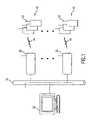
- FIG. 1shows wireless voice enabled terminals connected to a data network according to an exemplary embodiment of the present invention
- FIG. 2shows a diagram representing a software architecture of a voice enabled terminal according to an embodiment of the present invention
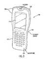
- FIG. 3shows an exemplary voice enabled terminal according to an embodiment of the present invention.
- FIG. 4shows an exemplary screen shot of the controls for the voice enabled terminal according to one embodiment of the invention.
- RF based portable transreceiversgenerally can transmit on many channels, with each channel being assigned a discrete frequency so that only radios tuned to the same channel can receive the transmission. However, multiple radios may be transmitting on the same channel, so that a transmission from one radio may be “stepped over” by another radio's transmission, and neither radio transmission can be heard.
- the present inventionuses a different technology to provide Walkie TalkieTM like functionality to a voice enabled terminal.
- several features that are not available with RF based portable transreceiversmay be implemented within the system according to the present invention.
- communications between the voice enabled terminalstravel over a data network, and thus are not subject to the same range limitations affecting RF based devices.
- the voice enabled terminalshave the “feel” and general usage characteristics of conventional RF portable transreceivers, so that their usage is intuitive to anyone familiar with the conventional RF units.
- FIG. 1shows one exemplary embodiment of a voice over IP (VOIP) portable transreceiver system, which mimics the functionality of RF based systems while incorporating additional features.
- a plurality of voice enabled terminals 10are interconnected and can provide voice communications amongst each other.
- each terminal 10is given to an user or group of users. Since terminals 10 are portable, they are capable of connecting to a wireless network, and are sufficiently small to be easily carried.
- terminals 10may be specifically designed to be used as portable transreceivers, or may be hand held devices with different purposes, to which the portable transreceiver functionality has been added.
- the terminalis based on a personal digital assistant (PDA) such as those using the Windows® CE operating system, or similar.
- PDApersonal digital assistant
- the PDAmay be a multi purpose PDA executing a software module which provides the portable transreceiver functionality, or may be a more specialized unit such as a PDA-scanner combination, which is also usable to read bar codes.
- a software modulewhich provides the portable transreceiver functionality
- PDA-scanner combinationwhich is also usable to read bar codes.
- different types of voice enabled terminalsmay be used to communicate over the same data network, as long as they operate under compatible protocols.
- Voice enabled terminals 10include a transmitter section including an antenna 12 , which enables them to communicate without being connected to wires.
- a wireless local area network (WLAN) 14may be used to connect each of the terminals 10 to access points 20 .
- WLANwireless local area network
- a multi purpose WLAN 14can be used, or the WLAN 14 may be a dedicated network used only for voice communications.
- Access points 20form the connection between WLAN 14 and the data network 16 to which all terminals 10 are ultimately connected.
- Access points 20act as a two way conduit, which receives radio transmissions from the transmitter section of terminals 10 , and forwards the transmissions to the data network 16 using the appropriate protocols.
- an internet protocolsuch as TCP/IP may be used to direct the transmission to its intended recipients on data network 16 .
- Various levels of data processingmay be carried out by access points 20 , for example for error correction or encryption purposes.
- Data network 16is the principal means by which voice messages are carried between terminals 10 .
- This networkcan be any network useable to transmit data, such as between microprocessors, and may be a local area network (LAN), a wide area network (WAN) or the Internet.
- LANlocal area network
- WANwide area network
- Using a data network to carry the voice communicationsgives a distinct advantage to the system according to the invention.
- the range of the portable transreceiver-like terminals 10is restricted only by the extent of data network 16 . When the Internet is used for this purpose, the range of terminals 10 can be essentially unlimited, as long as an access point 20 connected to network 16 is within range of each of the users.
- the structure of data networks 16provides a certain amount of redundancy since in case of failure of certain segments of the network other segments can be used to carry the data.
- the network protocol according to the present inventionprovides additional redundancy to minimize loss of data.
- the VoIP system of the inventionthus is more robust than conventional RF based portable transreceivers, which are subject to disruptions and interference.
- the system according to the inventionmay also provide security benefits compared to RF based devices. Since the transmissions travel over the airwaves only for short distances at low power, it is more difficult to intercept them. Also, since the signals are already in a form that can be used by a microprocessor, encryption operations are easier to carry out, for example using the Kerberos or Wired systems.
- the VoIP portable transreceiver (WT) systemprovides packet-based voice communication between users of wireless voice enabled terminals, such as those based on PDA devices manufactured by Symbol Technologies.
- the exemplary wireless terminalsoperate under the 802.11 b standard for wireless LAN's, thus providing interoperability between products of different manufacturers.
- the exemplary embodimentuses direct sequence radio frequency transmissions. However, frequency hopping spread spectrum RF modes and other non RF modes, such as infrared transmissions, may also be employed within WLAN 14 .
- One benefit of using the 802.11 b standardis that existing infrastructures using that standard may be adapted to support the VoIP WT system with minimal modifications. Most voice enabled terminal devices supporting that standard may be used as the portable transreceiver handset, often requiring simply a software upgrade to operate according to the invention.
- VoIP WT systemprovides the user with an interface consistent with conventional RF based systems.
- the operation of the VoIP WT systemshould appear familiar to users accustomed to conventional RF devices.
- terminals 10execute software modules that provide multiple “virtual” communications channels, which appear to the user as analogous to the different frequency channels found on RF units.
- Each VoIP WT unitmay be configured to have a primary channel that is used as the default channel for transmitting and for receiving, but the user can set the terminal to transmit and receive on any other desired channel, and to monitor some or all the available virtual channels.
- the VoIP WTis capable of receiving and transmitting over at least 256 discrete channels.
- the exemplary unitis capable of receiving any or all of those 256 channels, those of skill in the art will understand that all the channels must still travel over a common WLAN, since there is no separate network for each channel. Accordingly, irrespective of the number of channels supported by the VoIP WT, the system can deliver simultaneously only as many messages as can be supported by data networks 14 and 16 . The number of simultaneous messages that can be processed depends on the 802.11 b network architecture and on the specific site implementation.
- a channelmay be dedicated as a priority channel, for example to be used for high priority security messages. All the units connected to the data network, such as terminals 10 on network 16 , will receive the priority channel, and the messages received on the priority channel will override any other messages transmitted on different channels. When a message on the priority channel is received, all the units that are transmitting a message will abort the transmission, and notify the user that the transmission was discontinued. For example, an audible alert may be provided to the user for that purpose. Units that are in the receive mode will be prevented from starting a transmission while a priority message is being broadcast. All the units may have the ability to broadcast on the priority channel, or that feature may only be reserved for selected units.
- the portable transreceiverWhen the portable transreceiver according to the present invention is not active on the default channel or on the priority channel, it is capable of monitoring any of an assigned group of channels for incoming transmissions. However, before the unit is able to transmit on one of the monitored channels, a specific channel must be selected by the user. In another embodiment, units may be given the ability to transmit on multiple channels. Selecting a channel for transmission does not affect the channel that has been defined as the default channel for transmission and reception in a unit, which is also referred to as the designated primary channel of the unit. If a unit receives more than one message on different channels, which message is actually processed by the unit depends on a specific priority scheme. Priority or security broadcasts are handled first, so they are always played to the user.
- Priority messagesare followed by messages broadcast on the unit's designated primary channel, and finally by broadcasts on any other of the monitored channels. Messages that are received on the monitored channels are not interrupted by another, later message with the same priority level. Within messages of the same priority, the earlier received message is played.
- Conventional RF based portable transreceiver unitsdo not have any mechanism to prevent more than one unit from simultaneously broadcasting on the same channel when the users press the PTT switch.
- the VoIP WT systemprovides a mechanism to prevent this collision of transmissions.
- software in the unitis configured to verify that the channel selected is not already in use. If the selected channel is not in use, the transmission is broadcast normally. If, when the user presses the PTT switch a message is already being received on that channel, the transmit mode of the unit is disabled and a notification is issued to the user to indicate that the selected channel is busy.
- a race conditioncan take place when two or more units have their PTT switches pressed simultaneously, while using the same channel.
- multiple portable transreceiver unitsmay be allowed to begin their transmission streams.
- the racecan be resolved by configuring each voice enabled terminal unit in the system so that no more than one message is heard by all the units on the channel, to prevent any two listeners from hearing different messages after the collision has been detected.
- a VoIP WT unit that is transmittingdetects another transmission on the same channel, one of several acceptable actions may be taken. For example, all the units may stop transmitting, and may provide to the relevant users a notification of the race condition. Alternatively, a priority mechanism may be specified, to allow only one of the transmissions to continue, while suppressing all other interfering transmissions.
- a directory server 22may be connected to the data network 16 to provide a naming service for the system.
- a “group”, in the context of the present invention,is a named list of users that subscribe to a particular channel.
- the VoIP WT systemsupports a common directory based on server 22 which allows the management of user groups. The implementation of this functionality requires the presence of a centralized server 22 , and will thus be optional.
- the directory serviceis used to correlate a group name to a channel number, so that users don't have to remember which channel numbers correspond to which set of users. For example, a user may request that the VoIP WT unit monitor the “Purchasing” or the “Loading Bay 1 ” groups, without having to remember which channel numbers are associated with those groups.
- a public APImay be used to provide an application directory access to a centralized directory hosted on a server using the lightweight directory access protocol (LDAP).
- LDAPlightweight directory access protocol
- the application directorymay access a local directory implemented in a static text file.
- LDAP directory servermay be a server running Windows 2000®, particularly using Active Directory® software.
- the system according to embodiments of the present inventioncan also provide a telephone-like caller ID on each terminal, which indicates to each user an identification of who originated a transmission.
- This feature of the terminalsis not dependent on the directory service described above, although in some cases the directory service may be tied to the identification function.
- a name that identifies either the unit or the person using the unitis sent in the transmission, together with the data packets describing the voice communication and any other pertinent data.
- Each receiving unitcan then display the name of the sender or the originating terminal, as applicable.
- a peer-to-peer private modeis the integration of a peer-to-peer private mode with the traditional portable transreceiver mode of operation.
- Traditional RF based WT unitscan only provide a one-to-many broadcast mode, where the transmission is half duplex, meaning that only one user at a time may speak. This is replicated in the WT mode of operation of the VoIP WT system.
- the private modepermits one-to-one calling between two users, with full duplex transmissions in which both addressees may speak simultaneously. This mode provides the same functionality as a telephone call between the two users.
- a user at a receiving unitwill be able to initiate a private callback to the initiator of the last, or most recently active WT mode message.
- additional benefitsinclude reduced broadcast traffic, minimized distractions to other users not party to the peer-to-peer communication, and extended operating life of the non-participating units due to lower battery usage. This is possible since only two units participate in a private mode communication. Instead of tying up every terminal unit tuned to a specific virtual channel in the WT mode, users can select the private mode to limit communications to the two participating units.
- Specialized message traffic rulesmay be used to prioritize the reception of peer-to-peer mode messages and of the normal WT mode messages. For example, if a WT mode message is received while the unit is participating in a peer-to-peer call, the peer-to-peer call is given higher priority.
- the usermay be given a notification that a message is being received under the WT mode, and may be given the option of switching back to the WT mode of operation.
- the WT mode messagehas been received by a unit, the user can be given the option of responding to the message by using the normal broadcasting WT mode, or by using the private peer-to-peer mode. Selection of the WT mode may be made by simply pressing the PTT button of the unit.
- Peer-to-peer modemay be initiated by a separate soft or hard key, since it is not the default mode of operation of the VoIP WT device.
- each portable transreceiver unitincludes a memory that can buffer the most recent incoming voice message to provide a replay capability.
- the messageis longer than the configured buffer size, only the last portion of the message will be saved. The user will then be able to replay the buffered message.
- playback of the buffermay be interrupted to permit reception of the new message, particularly if the new message is received on the priority channel.
- An audio alertmay be used to further notify the user that buffer playback has been suspended to receive a real-time message.
- the buffermay be sufficient to store about 60 seconds of message.
- the VoIP WT systemis designed to minimize network loading as much as practical, since it must operate in a network that is used also by other types of network traffic. Latency of the WT system is reduced as much as possible, but to a certain extent is dependent on the actual network architecture. Latency of the half-duplex WT mode is not as critical as latency of the full-duplex private mode, since in WT mode multiple participants cannot speak simultaneously but instead have to take turns speaking.
- the network protocol chosen for the inventiontakes advantage of this lessened requirement of the WT mode to include redundant transmission of the voice data. This adds some latency to the message, but greatly improves the quality of the message. The redundant transmission allows the receiver to reconstruct missing voice data due to network interference or errors.
- the latency in the WT mode from the microphone of the transmitting unit to the speaker of the receiving unitaverages less than 500 milliseconds, excluding network delays.
- the latency from the transmitter's microphone to the receiver's speakeris less than 300 milliseconds, also excluding network delays.
- Various signal compression methodsmay be used to reduce the amount of bandwidth used by the VoIP WT application. For example, a G.729A codec is provided for voice compression, however other more effective methods may also be incorporated.
- FIG. 2is a diagram showing an exemplary embodiment of the software architecture and hardware interface used to control a VoIP WT unit such as the voice enabled terminal 10 .
- FIG. 2shows the software as applied to a PDT8100X3 platform, manufactured by Symbol Technologies®, using the 802.11 b protocol.
- the exemplary platformis a hand help PDA that also includes a bar code scanner in addition to the portable transreceiver features, and is particularly useful where users need to communicate with one another and to identify merchandise, such as in a warehouse. It will be apparent to those of skill in the art that a similar software architecture can be used in different voice enabled devices, without affecting the functionality of the device.
- an hardware interface 50includes the PDT8100X3 unit 52 and a Spectrum 24 adapter 54 having a radio network card with a transmitter/receiver used to connect terminal 10 to the access points 20 via WLAN 14 .
- the hardware componentalso includes a digital signal processor (DSP) 56 , used to process the voice communications, such as to perform signal compression tasks.
- DSPdigital signal processor
- the software componentsinclude software elements 60 that are part of the Windows CE® operating system, and software elements 70 that are specific to the portable transreceiver application, both of which are executed on a processor of the voice enabled device. It will be apparent that other operating systems adapted to run on portable devices may be used, such as Palm® operating systems, etc.
- Windows CE® operating system components 60are well known in the art, and include Wave in and out modules 62 to process sounds, Winsock module 64 to manage network sockets, and various drivers 66 for the display screen, etc. Additional software modules may be included with software elements 70 , which are developed specifically to manage operation of the VoIP WT functionality.
- the WT application module 72is the primary application that enables terminal 10 to be used as a portable transreceiver. WT application module 72 is designed to minimize interference with other applications that may be executed simultaneously on the unit, in particular other applications that use the notification driver 86 to provide audio cues.
- the WT application module 72operates in the background on the device, so that the full screen of the device (i.e. terminal 10 ) may be used for other applications.
- the application interfacemay be displayed automatically when needed, such as when an incoming message is detected.
- a “display pop” keymay be provided to toggle the WT application interface from the background to the foreground, and vice versa, each time it is pressed.
- This toggle keymay be a physical button or a touch screen region of the device.
- the userhas the option of operating in a low power mode, which may be entered by using a key. This mode blanks the screen and may perform other functions to reduce power consumption. In power save mode the unit is fully functional and can send or receive voice messages. If the user wants to see the screen, a key may be pressed to resume normal operations. If an event occurs which requires the user to see the screen, normal mode may be resumed automatically.
- Private call transport module 74enables the terminal 10 to be used in private mode communications, as described above.
- This modeuses, for example, the H.323 session protocol for telephone-like full duplex performance.
- Private call transport module 74typically does not provide session control, since that is handled by the H.323 protocol.
- the applicationaccesses H.232 for session control through the Microsoft Telephony API (TAPI).
- TSPTelephony service provider
- the Telephony service provider (TSP)manages call setup, call tear down and call control via the H.323 stack, and negotiates a common compression codec with the destination unit.
- module 74may also include power management functions, such as switching the unit between the power save mode (PSP) and the full power mode (CAM) as necessary.
- PSPpower save mode
- CAMfull power mode
- the unitnormally operates in the lowest power mode.
- the unitis switched to full-power mode.
- the unitwatches for a wake-up message, which is sent prior to a transmission as part of the protocol. If a wake-up message is received, the unit switches to full power mode. Since it is possible for a wake-up message to be lost, the radio also watches for regular voice packets. Therefore, if one of the regular voice packets is detected, the unit is also turned on to full power mode. After the last packet in a transmission is received, the unit waits a short time interval to see if additional packets will be received. If there are no additional data packets within a specified timeout period, the unit switches back into the low-power mode.
- WT call transport module 76provides one-to-many half duplex communications that replicate the functioning of a RF portable transreceiver.
- the voice signalsare sent using a multicast realtime transport protocol (RTP) standard for streaming, using a packet switched network.
- RTPrealtime transport protocol
- WT call transport module 76also provides a method to increase the audio quality of the transmission over an unreliable network. Since transmission over a data network can be unreliable and subject to various data errors, some form of error correction mechanism is required. The transmission of voice data must occur in real time, thus re-broadcasting the data packets representing the voice communication is not feasible.
- a simple redundancy schemeis used, in which each voice data packet is transmitted multiple times, and is reassembled at the receiver. Any missing information from any of the transmissions is likely to be present in the redundant transmission.
- two redundant packetsare used, resulting in each voice sample being sent three times.
- the directory service described aboveis implemented through the directory services module 78 of software elements 70 .
- Directory services module 70manages the interaction with server 22 , which provides naming services for groups of users. Additional modules that are part of the software elements 70 include the firmware and the drivers 84 that manage the operation of the spectrum 24 adapter, to enable the radio communications to access WLAN 14 . Also included is a voice compression services module 80 , which carries out voice compression operations to reduce the amount of network traffic required to transmit the voice data. In the exemplary embodiment, module 80 interacts with the firmware and driver 82 providing G.729A codecs for compression, which is carried out by the digital signal processor 56 . It will be apparent to those skilled in the art that the software architecture describe herein is exemplary only, and that the same functionality may be obtained using different operating systems and software configurations.
- FIG. 3shows a perspective view of an exemplary voice enabled terminal 100 according to the invention.
- Terminal 100is based on Symbol Technologies' PDT8100X3 portable data terminal, and includes a transmitter/receiver component 102 used to connect with WLAN 14 .
- transmitter/receiver component 102may be a Spectrum 24 wireless network radio card used to transmit outbound voice communications and receive inbound voice communications.
- the primary components of terminal 100are a microphone 104 and a speaker 106 which are adapted to reproduce the frequency range of human voice. Remote speakers and microphones may also be provided, connectable to terminal 100 with jacks.
- a push to talk (PTT) button 108is included to initiate a transmission, as is done in RF portable transreceivers and CB radios.
- PTTpush to talk
- PTT switch 108may also perform different functions, depending on which application is being executed by terminal 100 .
- a display 110may also be included to present to the user a graphical interface to access the VoIP WT system and other applications.
- a keyboard 112may be provided, to enter commands and to select options within the WT application, and for other applications that are executable by terminal 100 .
- FIG. 4An exemplary screen shot of display 110 is shown in FIG. 4 .
- the WT applicationruns under the Microsoft Windows CE operating system, or the Microsoft Pocket PC 2002 operating system.
- the PTT switchis preferably a physical switch, but other functions of the WT application may be selected using soft keys and/or the touchscreen 110 of the device.
- the WT applicationexecutes as a background process, and only shows as a small icon on the PDA's display.
- the WT applicationis activated, and a display such as display 120 is shown.
- Display 120is preferably designed to follow the operating system's convention, such as having a top bar 122 with the name of the application and a button to minimize the window.
- a status area 124may be provided to indicate whether the portable transreceiver system is idle, operating in the WT mode, or in the peer-to-peer mode. Additional status messages may be displayed as necessary.
- a pair of touch sensitive keys 126can be used to select the channel to be monitored and the channel to be used for transmitting. The channel number is displayed in field 130 , and the channel name in field 128 . If required, submenus may be provided to select multiple channels or groups to be monitored.
- a directory key 132is used to bring up additional screens that allow the user to access the naming service of server 22 .
- a volume bar 134 and muting button 136may replace or supplement physical volume controls of terminal 100 .
- a replay button or touch sensitive area 138can be used to play back a portion of the latest received voice message, and an additional screen may be invoked to let the user set recording and playback parameters.
- a callback area 140is provided to let the user initiate a peer-to-peer communication with another user. In a simple form, when key 140 is pressed, the user that originated the last communication received would be called back. In more sophisticated applications, a different screen may be provided which lets the user select whom to contact in the peer-to-peer mode.
- Additional screensmay be provided as needed, to let the user select options and set parameters for the various functions of the WT application.
- a “tools” key 142may be provided to access functions not shown on primary screen 120 . It will be apparent that the specific screen configuration and layout of the physical controls and touch screen areas can vary depending on the design of the unit and the operating system being used.
Landscapes
- Engineering & Computer Science (AREA)
- Signal Processing (AREA)
- Computer Networks & Wireless Communication (AREA)
- Multimedia (AREA)
- Business, Economics & Management (AREA)
- General Business, Economics & Management (AREA)
- Computer Security & Cryptography (AREA)
- Mobile Radio Communication Systems (AREA)
- Telephonic Communication Services (AREA)
Abstract
Description
Claims (26)
Priority Applications (5)
| Application Number | Priority Date | Filing Date | Title |
|---|---|---|---|
| US10/338,938US7023821B2 (en) | 2002-04-12 | 2003-01-08 | Voice over IP portable transreceiver |
| EP04700859AEP1582077A4 (en) | 2003-01-08 | 2004-01-08 | PORTABLE IP VOICE TRANSCEIVER |
| PCT/US2004/000345WO2004064359A2 (en) | 2003-01-08 | 2004-01-08 | Voice over ip portable transreceiver |
| US11/332,457US20060126560A1 (en) | 2002-04-12 | 2006-01-13 | Voice over IP portable transreceiver |
| US11/332,442US20060114854A1 (en) | 2002-04-12 | 2006-01-13 | Voice over IP portable transreceiver |
Applications Claiming Priority (2)
| Application Number | Priority Date | Filing Date | Title |
|---|---|---|---|
| US37221902P | 2002-04-12 | 2002-04-12 | |
| US10/338,938US7023821B2 (en) | 2002-04-12 | 2003-01-08 | Voice over IP portable transreceiver |
Related Child Applications (2)
| Application Number | Title | Priority Date | Filing Date |
|---|---|---|---|
| US11/332,457DivisionUS20060126560A1 (en) | 2002-04-12 | 2006-01-13 | Voice over IP portable transreceiver |
| US11/332,442ContinuationUS20060114854A1 (en) | 2002-04-12 | 2006-01-13 | Voice over IP portable transreceiver |
Publications (2)
| Publication Number | Publication Date |
|---|---|
| US20030193930A1 US20030193930A1 (en) | 2003-10-16 |
| US7023821B2true US7023821B2 (en) | 2006-04-04 |
Family
ID=32711011
Family Applications (3)
| Application Number | Title | Priority Date | Filing Date |
|---|---|---|---|
| US10/338,938Expired - LifetimeUS7023821B2 (en) | 2002-04-12 | 2003-01-08 | Voice over IP portable transreceiver |
| US11/332,442AbandonedUS20060114854A1 (en) | 2002-04-12 | 2006-01-13 | Voice over IP portable transreceiver |
| US11/332,457AbandonedUS20060126560A1 (en) | 2002-04-12 | 2006-01-13 | Voice over IP portable transreceiver |
Family Applications After (2)
| Application Number | Title | Priority Date | Filing Date |
|---|---|---|---|
| US11/332,442AbandonedUS20060114854A1 (en) | 2002-04-12 | 2006-01-13 | Voice over IP portable transreceiver |
| US11/332,457AbandonedUS20060126560A1 (en) | 2002-04-12 | 2006-01-13 | Voice over IP portable transreceiver |
Country Status (3)
| Country | Link |
|---|---|
| US (3) | US7023821B2 (en) |
| EP (1) | EP1582077A4 (en) |
| WO (1) | WO2004064359A2 (en) |
Cited By (13)
| Publication number | Priority date | Publication date | Assignee | Title |
|---|---|---|---|---|
| US20040066751A1 (en)* | 2002-09-24 | 2004-04-08 | Kuo-Kun Tseng | Duplex aware adaptive playout method and communications device |
| US20060114854A1 (en)* | 2002-04-12 | 2006-06-01 | Kent Wotherspoon | Voice over IP portable transreceiver |
| US20070030834A1 (en)* | 2005-08-05 | 2007-02-08 | Rappaport Matthew B | Systems and methods for facilitating communications over a shared channel |
| US20070280189A1 (en)* | 2006-06-04 | 2007-12-06 | Asustek Computer Inc. | Voice over Internet protocol system and related wireless local area network device |
| US20080025250A1 (en)* | 2006-07-28 | 2008-01-31 | Motorola, Inc. | Method and system for setting paging indication sequences in paging messages |
| US20080139251A1 (en)* | 2005-01-12 | 2008-06-12 | Yuuichi Yamaguchi | Push-To-Talk Over Cellular System, Portable Terminal, Server Apparatus, Pointer Display Method, And Program Thereof |
| US8046625B2 (en) | 2008-02-22 | 2011-10-25 | Hill-Rom Services, Inc. | Distributed fault tolerant architecture for a healthcare communication system |
| US8126442B2 (en) | 2007-05-31 | 2012-02-28 | Saint Francis University | RF to IP bridge system and method of use |
| TWI558259B (en)* | 2011-08-31 | 2016-11-11 | 三星電子股份有限公司 | Method of wirelessly connecting at least two devices and wirelessly connectable device using the same |
| US9673890B2 (en) | 2003-11-15 | 2017-06-06 | Aeroflex Plainview, Inc. | Using modulation-transcendent RF sampled digital data over an IP connection |
| US10136815B2 (en) | 2012-09-24 | 2018-11-27 | Physio-Control, Inc. | Patient monitoring device with remote alert |
| US11504061B2 (en) | 2017-03-21 | 2022-11-22 | Stryker Corporation | Systems and methods for ambient energy powered physiological parameter monitoring |
| US12251243B2 (en) | 2008-02-22 | 2025-03-18 | Hill-Rom Services, Inc. | Distributed healthcare communication system |
Families Citing this family (29)
| Publication number | Priority date | Publication date | Assignee | Title |
|---|---|---|---|---|
| US20040077316A1 (en)* | 2002-10-16 | 2004-04-22 | Wei Xiong | Use of power detection to control RX/TX switching |
| US7251683B1 (en)* | 2002-10-25 | 2007-07-31 | Sandeep Shah | Information handling system including arrangements for initiating an application in response to usage of cross reference between information and for initiating usage of a workflow flow chart associated with and information work |
| US8676249B2 (en)* | 2003-05-19 | 2014-03-18 | Tahnk Wireless Co., Llc | Apparatus and method for increased security of wireless transactions |
| US20090015379A1 (en)* | 2004-05-19 | 2009-01-15 | Einar Rosenberg | Apparatus and method for context-based wireless information processing |
| US7613172B2 (en)* | 2003-12-24 | 2009-11-03 | Watchguard Technologies, Inc. | Method and apparatus for controlling unsolicited messaging |
| US20050186992A1 (en)* | 2004-02-20 | 2005-08-25 | Slawomir Skret | Method and apparatus to allow two way radio users to access voice enabled applications |
| US7489648B2 (en)* | 2004-03-11 | 2009-02-10 | Cisco Technology, Inc. | Optimizing 802.11 power-save for VLAN |
| CA2604097A1 (en)* | 2005-04-14 | 2006-10-26 | Any Corner Llc | Systems and methods for a multimedia communications system |
| US20060253770A1 (en)* | 2005-05-05 | 2006-11-09 | Qi Bi | Point-to-talk service |
| US20070254709A1 (en)* | 2006-04-28 | 2007-11-01 | Motorola, Inc. | Method and system for unambiguous accessory association |
| US7852992B1 (en)* | 2006-11-14 | 2010-12-14 | Avaya Inc. | Methods and apparatus for audio communication |
| KR101358224B1 (en)* | 2007-06-19 | 2014-02-05 | 엘지전자 주식회사 | Apparatus and method for supporting multi language |
| US8433283B2 (en) | 2009-01-27 | 2013-04-30 | Ymax Communications Corp. | Computer-related devices and techniques for facilitating an emergency call via a cellular or data network using remote communication device identifying information |
| US8134943B2 (en) | 2009-02-02 | 2012-03-13 | Qualcomm Incorporated | Repeating multicast message transmissions in a wireless communications system |
| US8311038B2 (en)* | 2009-03-30 | 2012-11-13 | Martin Feuerhahn | Instant internet browser based VoIP system |
| US9736675B2 (en)* | 2009-05-12 | 2017-08-15 | Avaya Inc. | Virtual machine implementation of multiple use context executing on a communication device |
| US20110173060A1 (en)* | 2010-01-08 | 2011-07-14 | Gallagher Kevin N | Guest Check Presenter Having a Wireless Communication Device |
| US8744401B2 (en)* | 2011-05-20 | 2014-06-03 | Continental Automotive Systems, Inc. | Enhanced telematic emergency response |
| US10163064B2 (en) | 2012-04-03 | 2018-12-25 | Sears Brands, L.L.C. | Methods and systems for connected sales associate services |
| US20190287068A1 (en)* | 2012-04-03 | 2019-09-19 | Transform Sr Brands Llc | Methods and systems for connected sales associate services |
| US10242343B2 (en)* | 2012-04-03 | 2019-03-26 | Sears Brands, L.L.C. | Methods and systems for connected sales associate services |
| US9204263B2 (en) | 2012-05-23 | 2015-12-01 | Mark A. Lindner | Systems and methods for establishing a group communication based on motion of a mobile device |
| US9560099B2 (en) | 2012-05-23 | 2017-01-31 | Qualcomm Incorporated | Systems and methods for group communication using a mobile device using motion and voice activate controls |
| US9674694B2 (en) | 2012-05-23 | 2017-06-06 | Qualcomm Incorporated | Systems and methods for group communication using a mobile device with mode transition based on motion |
| US9392421B2 (en) | 2012-05-23 | 2016-07-12 | Qualcomm Incorporated | Systems and methods for group communication using a mobile device with mode depending on user proximity or device position |
| WO2013181017A2 (en)* | 2012-06-01 | 2013-12-05 | Sears Brands, Llc | Methods and systems for connected sales associate services |
| US20140075311A1 (en)* | 2012-09-11 | 2014-03-13 | Jesse William Boettcher | Methods and apparatus for controlling audio volume on an electronic device |
| KR101943989B1 (en) | 2015-06-05 | 2019-01-30 | 삼성전자주식회사 | Method, server and terminal for transmitting and receiving data |
| US20230179961A1 (en)* | 2021-12-07 | 2023-06-08 | Rugged Race Products, Inc. | Radio crew isolation system |
Citations (15)
| Publication number | Priority date | Publication date | Assignee | Title |
|---|---|---|---|---|
| US4553263A (en)* | 1983-12-22 | 1985-11-12 | Motorola, Inc. | Queued community repeater mobile |
| US5793749A (en)* | 1994-12-22 | 1998-08-11 | Motorola, Inc. | Method and apparatus for communications testing using a recorded test message |
| US5852405A (en)* | 1995-03-17 | 1998-12-22 | Fujitsu Limited | Wireless LAN system |
| US6005851A (en)* | 1997-10-10 | 1999-12-21 | Nortel Networks Corporation | Adaptive channel control for data service delivery |
| US6230010B1 (en)* | 1989-10-31 | 2001-05-08 | Walker C. Morris | Method and apparatus for transmission of analog and digital |
| US6240140B1 (en)* | 1997-02-24 | 2001-05-29 | Picturetel Corporation | Channel aggregation having low latency and overhead |
| US6353611B1 (en)* | 1995-11-27 | 2002-03-05 | At&T Corp. | Call waiting feature for a telephone line connected to the internet |
| US6393001B1 (en)* | 1997-06-13 | 2002-05-21 | Nippon Telegraph And Telephone Corporation | Satellite communication system, routing method for the system and storage device with program of the routing |
| US6456973B1 (en)* | 1999-10-12 | 2002-09-24 | International Business Machines Corp. | Task automation user interface with text-to-speech output |
| US6493335B1 (en)* | 1996-09-24 | 2002-12-10 | At&T Corp. | Method and system for providing low-cost high-speed data services |
| US6496489B1 (en)* | 1993-11-01 | 2002-12-17 | Telefonaktiebolaget Lm Ericsson | Method and apparatus for distinguishing between a digital control channel and a digital traffic channel in a radiocommunication system |
| US20030081582A1 (en)* | 2001-10-25 | 2003-05-01 | Nikhil Jain | Aggregating multiple wireless communication channels for high data rate transfers |
| US20030099221A1 (en)* | 2001-11-28 | 2003-05-29 | Sokwoo Rhee | Network protocol |
| US20030152053A1 (en)* | 1998-03-06 | 2003-08-14 | David H Evans | Wireless local area network system |
| US6636738B1 (en)* | 1999-07-07 | 2003-10-21 | Sony Corporation | Radio-network control apparatus and radio-network control method |
Family Cites Families (11)
| Publication number | Priority date | Publication date | Assignee | Title |
|---|---|---|---|---|
| US5227775A (en)* | 1988-05-09 | 1993-07-13 | Motorola Inc. | Method and arrangement for channel monitor and control |
| US5726984A (en)* | 1989-01-31 | 1998-03-10 | Norand Corporation | Hierarchical data collection network supporting packetized voice communications among wireless terminals and telephones |
| US6366771B1 (en)* | 1995-06-21 | 2002-04-02 | Arron S. Angle | Wireless communication network having voice and data communication capability |
| US5699357A (en)* | 1996-03-06 | 1997-12-16 | Bbn Corporation | Personal data network |
| US6178173B1 (en)* | 1996-12-30 | 2001-01-23 | Paradyne Corporation | System and method for communicating pre-connect information in a digital communication system |
| GB9813390D0 (en)* | 1998-06-23 | 1998-08-19 | Koninkl Philips Electronics Nv | Telecommunication system with channel sharing |
| US7046632B2 (en)* | 2000-04-01 | 2006-05-16 | Via Technologies, Inc. | Method and switch controller for relieving flow congestion in network |
| EP1182895A1 (en)* | 2000-08-15 | 2002-02-27 | Lucent Technologies Inc. | Method and apparatus for performing a voice dispatch call in a digital communication system |
| US20020037001A1 (en)* | 2000-09-28 | 2002-03-28 | General Instrument Corporation | VoIP phone line eliminator |
| US7386000B2 (en)* | 2001-04-17 | 2008-06-10 | Nokia Corporation | Packet mode speech communication |
| US7023821B2 (en)* | 2002-04-12 | 2006-04-04 | Symnbol Technologies, Inc. | Voice over IP portable transreceiver |
- 2003
- 2003-01-08USUS10/338,938patent/US7023821B2/ennot_activeExpired - Lifetime
- 2004
- 2004-01-08WOPCT/US2004/000345patent/WO2004064359A2/enactiveApplication Filing
- 2004-01-08EPEP04700859Apatent/EP1582077A4/ennot_activeWithdrawn
- 2006
- 2006-01-13USUS11/332,442patent/US20060114854A1/ennot_activeAbandoned
- 2006-01-13USUS11/332,457patent/US20060126560A1/ennot_activeAbandoned
Patent Citations (15)
| Publication number | Priority date | Publication date | Assignee | Title |
|---|---|---|---|---|
| US4553263A (en)* | 1983-12-22 | 1985-11-12 | Motorola, Inc. | Queued community repeater mobile |
| US6230010B1 (en)* | 1989-10-31 | 2001-05-08 | Walker C. Morris | Method and apparatus for transmission of analog and digital |
| US6496489B1 (en)* | 1993-11-01 | 2002-12-17 | Telefonaktiebolaget Lm Ericsson | Method and apparatus for distinguishing between a digital control channel and a digital traffic channel in a radiocommunication system |
| US5793749A (en)* | 1994-12-22 | 1998-08-11 | Motorola, Inc. | Method and apparatus for communications testing using a recorded test message |
| US5852405A (en)* | 1995-03-17 | 1998-12-22 | Fujitsu Limited | Wireless LAN system |
| US6353611B1 (en)* | 1995-11-27 | 2002-03-05 | At&T Corp. | Call waiting feature for a telephone line connected to the internet |
| US6493335B1 (en)* | 1996-09-24 | 2002-12-10 | At&T Corp. | Method and system for providing low-cost high-speed data services |
| US6240140B1 (en)* | 1997-02-24 | 2001-05-29 | Picturetel Corporation | Channel aggregation having low latency and overhead |
| US6393001B1 (en)* | 1997-06-13 | 2002-05-21 | Nippon Telegraph And Telephone Corporation | Satellite communication system, routing method for the system and storage device with program of the routing |
| US6005851A (en)* | 1997-10-10 | 1999-12-21 | Nortel Networks Corporation | Adaptive channel control for data service delivery |
| US20030152053A1 (en)* | 1998-03-06 | 2003-08-14 | David H Evans | Wireless local area network system |
| US6636738B1 (en)* | 1999-07-07 | 2003-10-21 | Sony Corporation | Radio-network control apparatus and radio-network control method |
| US6456973B1 (en)* | 1999-10-12 | 2002-09-24 | International Business Machines Corp. | Task automation user interface with text-to-speech output |
| US20030081582A1 (en)* | 2001-10-25 | 2003-05-01 | Nikhil Jain | Aggregating multiple wireless communication channels for high data rate transfers |
| US20030099221A1 (en)* | 2001-11-28 | 2003-05-29 | Sokwoo Rhee | Network protocol |
Cited By (38)
| Publication number | Priority date | Publication date | Assignee | Title |
|---|---|---|---|---|
| US20060114854A1 (en)* | 2002-04-12 | 2006-06-01 | Kent Wotherspoon | Voice over IP portable transreceiver |
| US20040066751A1 (en)* | 2002-09-24 | 2004-04-08 | Kuo-Kun Tseng | Duplex aware adaptive playout method and communications device |
| US7269141B2 (en)* | 2002-09-24 | 2007-09-11 | Accton Technology Corporation | Duplex aware adaptive playout method and communications device |
| US9673890B2 (en) | 2003-11-15 | 2017-06-06 | Aeroflex Plainview, Inc. | Using modulation-transcendent RF sampled digital data over an IP connection |
| US20080139251A1 (en)* | 2005-01-12 | 2008-06-12 | Yuuichi Yamaguchi | Push-To-Talk Over Cellular System, Portable Terminal, Server Apparatus, Pointer Display Method, And Program Thereof |
| US7966030B2 (en)* | 2005-01-12 | 2011-06-21 | Nec Corporation | Push-to-talk over cellular system, portable terminal, server apparatus, pointer display method, and program thereof |
| US8385924B2 (en) | 2005-08-05 | 2013-02-26 | Atc Technologies | Systems and methods for facilitating communications over a shared channel |
| US7835760B2 (en)* | 2005-08-05 | 2010-11-16 | Mobile Satellite Ventures, Lp | Systems and methods for facilitating communications over a shared channel |
| US20110026404A1 (en)* | 2005-08-05 | 2011-02-03 | Mobile Satellite Ventures, Lp | Systems and methods for facilitating communications over a shared channel |
| US20070030834A1 (en)* | 2005-08-05 | 2007-02-08 | Rappaport Matthew B | Systems and methods for facilitating communications over a shared channel |
| US20070280189A1 (en)* | 2006-06-04 | 2007-12-06 | Asustek Computer Inc. | Voice over Internet protocol system and related wireless local area network device |
| US8121099B2 (en)* | 2006-06-04 | 2012-02-21 | Asustek Computer Inc. | Voice over internet protocol system and related wireless local area network device |
| US20080025250A1 (en)* | 2006-07-28 | 2008-01-31 | Motorola, Inc. | Method and system for setting paging indication sequences in paging messages |
| US8126442B2 (en) | 2007-05-31 | 2012-02-28 | Saint Francis University | RF to IP bridge system and method of use |
| US8598995B2 (en) | 2008-02-22 | 2013-12-03 | Hill-Rom Services, Inc. | Distributed healthcare communication system |
| US8046625B2 (en) | 2008-02-22 | 2011-10-25 | Hill-Rom Services, Inc. | Distributed fault tolerant architecture for a healthcare communication system |
| US8392747B2 (en) | 2008-02-22 | 2013-03-05 | Hill-Rom Services, Inc. | Distributed fault tolerant architecture for a healthcare communication system |
| US8456286B2 (en) | 2008-02-22 | 2013-06-04 | Hill-Rom Services, Inc. | User station for healthcare communication system |
| US8169304B2 (en) | 2008-02-22 | 2012-05-01 | Hill-Rom Services, Inc. | User station for healthcare communication system |
| US8762766B2 (en) | 2008-02-22 | 2014-06-24 | Hill-Rom Services, Inc. | Distributed fault tolerant architecture for a healthcare communication system |
| US8803669B2 (en) | 2008-02-22 | 2014-08-12 | Hill-Rom Services, Inc. | User station for healthcare communication system |
| US9235979B2 (en) | 2008-02-22 | 2016-01-12 | Hill-Rom Services, Inc. | User station for healthcare communication system |
| US9299242B2 (en) | 2008-02-22 | 2016-03-29 | Hill-Rom Services, Inc. | Distributed healthcare communication system |
| US12251243B2 (en) | 2008-02-22 | 2025-03-18 | Hill-Rom Services, Inc. | Distributed healthcare communication system |
| US9517035B2 (en) | 2008-02-22 | 2016-12-13 | Hill-Rom Services, Inc. | Distributed healthcare communication system |
| US8384526B2 (en) | 2008-02-22 | 2013-02-26 | Hill-Rom Services, Inc. | Indicator apparatus for healthcare communication system |
| US9955926B2 (en) | 2008-02-22 | 2018-05-01 | Hill-Rom Services, Inc. | Distributed healthcare communication system |
| US11944467B2 (en) | 2008-02-22 | 2024-04-02 | Hill-Rom Services, Inc. | Distributed healthcare communication system |
| US11696731B2 (en) | 2008-02-22 | 2023-07-11 | Hill-Room Services, Inc. | Distributed healthcare communication method |
| US10307113B2 (en) | 2008-02-22 | 2019-06-04 | Hill-Rom Services, Inc. | Distributed healthcare communication system |
| US10638983B2 (en) | 2008-02-22 | 2020-05-05 | Hill-Rom Services, Inc. | Distributed healthcare communication system |
| US11058368B2 (en) | 2008-02-22 | 2021-07-13 | Hill-Rom Services, Inc. | Distributed healthcare communication system |
| US10021724B2 (en) | 2011-08-31 | 2018-07-10 | Samsung Electronics Co., Ltd. | Method of wirelessly connecting at least two devices and wirelessly connectable device using the method |
| TWI558259B (en)* | 2011-08-31 | 2016-11-11 | 三星電子股份有限公司 | Method of wirelessly connecting at least two devices and wirelessly connectable device using the same |
| US11457808B2 (en) | 2012-09-24 | 2022-10-04 | Physio-Control, Inc. | Patient monitoring device with remote alert |
| US10136815B2 (en) | 2012-09-24 | 2018-11-27 | Physio-Control, Inc. | Patient monitoring device with remote alert |
| US12064207B2 (en) | 2012-09-24 | 2024-08-20 | Physio-Control, Inc. | Patient monitoring device with remote alert |
| US11504061B2 (en) | 2017-03-21 | 2022-11-22 | Stryker Corporation | Systems and methods for ambient energy powered physiological parameter monitoring |
Also Published As
| Publication number | Publication date |
|---|---|
| US20060114854A1 (en) | 2006-06-01 |
| US20060126560A1 (en) | 2006-06-15 |
| EP1582077A2 (en) | 2005-10-05 |
| US20030193930A1 (en) | 2003-10-16 |
| WO2004064359A2 (en) | 2004-07-29 |
| EP1582077A4 (en) | 2007-07-25 |
| WO2004064359A3 (en) | 2004-12-09 |
Similar Documents
| Publication | Publication Date | Title |
|---|---|---|
| US7023821B2 (en) | Voice over IP portable transreceiver | |
| US10826957B2 (en) | Instant communications system having established communication channels between communication devices | |
| US7751348B2 (en) | Method and system for providing a push-to-talk communication session | |
| EP2374290B1 (en) | Method and apparatus for dual/multi-watch for group ptt services | |
| US8145249B2 (en) | Method and system for providing a proxy media service | |
| US20180103360A1 (en) | Dual-Mode Device for Voice Communication | |
| US8116823B2 (en) | Modular ear-piece/microphone (headset) operable to service voice activated commands | |
| US8406801B1 (en) | Communication systems and methods | |
| JP5777983B2 (en) | System and method for multiple simultaneous group communications in a wireless system | |
| US12278854B2 (en) | Instant communications system having established communication channels between communication devices | |
| US8364153B2 (en) | Mobile interoperability workstation controller having video capabilities within an incident communications network | |
| US20070105578A1 (en) | Method and system for providing a push-to-talk communication session using a control endpoint | |
| US20040058674A1 (en) | Multi-homing and multi-hosting of wireless audio subsystems | |
| US20060040695A1 (en) | Method of group call service using push to talk scheme in mobile communication terminal | |
| US20070243898A1 (en) | Multi-handset cordless voice over IP telephony system | |
| EP1949588A2 (en) | Method and system for providing a push-to-talk communication session | |
| US7536195B2 (en) | Method for PTT service in the push to talk portable terminal | |
| US20040203978A1 (en) | Bridging talk group in communication systems | |
| US20060089180A1 (en) | Mobile communication terminal | |
| JP4440166B2 (en) | Telephone, server device and communication method | |
| WO2008133855A1 (en) | Apparatus and method for multiple stage media communications | |
| WO2003094383A1 (en) | Wireless conferencing system | |
| KR100605832B1 (en) | Receiving Status Notification Method | |
| US20100255874A1 (en) | Dual mode communication device and method for carrying out a loud-speaking group meeting |
Legal Events
| Date | Code | Title | Description |
|---|---|---|---|
| AS | Assignment | Owner name:SYMBOL TECHNOLOGIES, INC., NEW YORK Free format text:ASSIGNMENT OF ASSIGNORS INTEREST;ASSIGNORS:WOTHERSPOON, KENT;CALLOW, GERALD;REEL/FRAME:013744/0227 Effective date:20030130 | |
| FEPP | Fee payment procedure | Free format text:PAYOR NUMBER ASSIGNED (ORIGINAL EVENT CODE: ASPN); ENTITY STATUS OF PATENT OWNER: LARGE ENTITY | |
| STCF | Information on status: patent grant | Free format text:PATENTED CASE | |
| CC | Certificate of correction | ||
| FPAY | Fee payment | Year of fee payment:4 | |
| FPAY | Fee payment | Year of fee payment:8 | |
| AS | Assignment | Owner name:MORGAN STANLEY SENIOR FUNDING, INC. AS THE COLLATERAL AGENT, MARYLAND Free format text:SECURITY AGREEMENT;ASSIGNORS:ZIH CORP.;LASER BAND, LLC;ZEBRA ENTERPRISE SOLUTIONS CORP.;AND OTHERS;REEL/FRAME:034114/0270 Effective date:20141027 Owner name:MORGAN STANLEY SENIOR FUNDING, INC. AS THE COLLATE Free format text:SECURITY AGREEMENT;ASSIGNORS:ZIH CORP.;LASER BAND, LLC;ZEBRA ENTERPRISE SOLUTIONS CORP.;AND OTHERS;REEL/FRAME:034114/0270 Effective date:20141027 | |
| AS | Assignment | Owner name:SYMBOL TECHNOLOGIES, LLC, NEW YORK Free format text:CHANGE OF NAME;ASSIGNOR:SYMBOL TECHNOLOGIES, INC.;REEL/FRAME:036083/0640 Effective date:20150410 | |
| AS | Assignment | Owner name:SYMBOL TECHNOLOGIES, INC., NEW YORK Free format text:RELEASE BY SECURED PARTY;ASSIGNOR:MORGAN STANLEY SENIOR FUNDING, INC.;REEL/FRAME:036371/0738 Effective date:20150721 | |
| MAFP | Maintenance fee payment | Free format text:PAYMENT OF MAINTENANCE FEE, 12TH YEAR, LARGE ENTITY (ORIGINAL EVENT CODE: M1553) Year of fee payment:12 |