US7022993B1 - Infrared leak detector - Google Patents
Infrared leak detectorDownload PDFInfo
- Publication number
- US7022993B1 US7022993B1US10/899,182US89918204AUS7022993B1US 7022993 B1US7022993 B1US 7022993B1US 89918204 AUS89918204 AUS 89918204AUS 7022993 B1US7022993 B1US 7022993B1
- Authority
- US
- United States
- Prior art keywords
- leak
- detector
- gas
- chamber
- housing
- Prior art date
- Legal status (The legal status is an assumption and is not a legal conclusion. Google has not performed a legal analysis and makes no representation as to the accuracy of the status listed.)
- Expired - Lifetime
Links
Images


Classifications
- G—PHYSICS
- G01—MEASURING; TESTING
- G01N—INVESTIGATING OR ANALYSING MATERIALS BY DETERMINING THEIR CHEMICAL OR PHYSICAL PROPERTIES
- G01N21/00—Investigating or analysing materials by the use of optical means, i.e. using sub-millimetre waves, infrared, visible or ultraviolet light
- G01N21/01—Arrangements or apparatus for facilitating the optical investigation
- G01N21/11—Filling or emptying of cuvettes
- G—PHYSICS
- G01—MEASURING; TESTING
- G01M—TESTING STATIC OR DYNAMIC BALANCE OF MACHINES OR STRUCTURES; TESTING OF STRUCTURES OR APPARATUS, NOT OTHERWISE PROVIDED FOR
- G01M3/00—Investigating fluid-tightness of structures
- G01M3/02—Investigating fluid-tightness of structures by using fluid or vacuum
- G01M3/04—Investigating fluid-tightness of structures by using fluid or vacuum by detecting the presence of fluid at the leakage point
- G01M3/042—Investigating fluid-tightness of structures by using fluid or vacuum by detecting the presence of fluid at the leakage point by using materials which expand, contract, disintegrate, or decompose in contact with a fluid
- G01M3/045—Investigating fluid-tightness of structures by using fluid or vacuum by detecting the presence of fluid at the leakage point by using materials which expand, contract, disintegrate, or decompose in contact with a fluid with electrical detection means
- G01M3/047—Investigating fluid-tightness of structures by using fluid or vacuum by detecting the presence of fluid at the leakage point by using materials which expand, contract, disintegrate, or decompose in contact with a fluid with electrical detection means with photo-electrical detection means, e.g. using optical fibres
- G—PHYSICS
- G01—MEASURING; TESTING
- G01N—INVESTIGATING OR ANALYSING MATERIALS BY DETERMINING THEIR CHEMICAL OR PHYSICAL PROPERTIES
- G01N21/00—Investigating or analysing materials by the use of optical means, i.e. using sub-millimetre waves, infrared, visible or ultraviolet light
- G01N21/17—Systems in which incident light is modified in accordance with the properties of the material investigated
- G01N21/25—Colour; Spectral properties, i.e. comparison of effect of material on the light at two or more different wavelengths or wavelength bands
- G01N21/31—Investigating relative effect of material at wavelengths characteristic of specific elements or molecules, e.g. atomic absorption spectrometry
- G01N21/35—Investigating relative effect of material at wavelengths characteristic of specific elements or molecules, e.g. atomic absorption spectrometry using infrared light
- G01N21/3504—Investigating relative effect of material at wavelengths characteristic of specific elements or molecules, e.g. atomic absorption spectrometry using infrared light for analysing gases, e.g. multi-gas analysis
- G—PHYSICS
- G01—MEASURING; TESTING
- G01N—INVESTIGATING OR ANALYSING MATERIALS BY DETERMINING THEIR CHEMICAL OR PHYSICAL PROPERTIES
- G01N2201/00—Features of devices classified in G01N21/00
- G01N2201/02—Mechanical
- G01N2201/022—Casings
- G01N2201/0221—Portable; cableless; compact; hand-held
Definitions
- This inventionrelates to gas leak detection and in particular to methods and devices using infrared optical chambers with circuits in a portable gas leak detector.
- Leak detectorshave been used for many applications which include detecting the concentration of specific types of gases.
- a leak detectorcan be designed to detect the concentration of refrigerant gas in surrounding ambient air. This application is important, as leaking refrigerant gas can pose a threat to both health and the environment.
- gasrefers to any gaseous matter and may refer to, e.g., a combination of elemental gasses, and e.g., (ambient atmospheric gas “air”).
- infrared technologyhas existed for many years, infrared technology has not been previously used for leak detection applications for many reasons. For example, manufacturing costs would have made the use of infrared technology too expensive to be used as a leak detector.
- a “closed path” type refrigerant monitorhas been previously proposed for passing a modulated light beam through a gas to be analyzed and then to an optical detector, all within a closed optical chamber.
- the detected lightis analyzed to provide information about the gas (for example, concentration).
- the detected light energymay be bandwidth limited such that a specific range of wavelengths is detected to facilitate analysis of particular gasses.
- problems with the “closed path” monitorsFor example, analysis is complicated by very little light energy being absorbed by low gas concentrations, substantial low frequency noise present in the analysis system and optical losses associated with typical optical pathways.
- a primary objective of the inventionis to provide an infrared leak detector that can be both portable and battery powered.
- a secondary objective of the inventionis to provide an infrared leak detector that can both portable and electrical cord powered.
- a third objective of the inventionis to provide an infrared leak detector that can operate within a one second or less response time.
- a fourth objective of the inventionis to provide an infrared leak detector having a long sensor life that does not become easily degraded by exposure to large leaks or other reactive gases.
- a fifth objective of the inventionis to provide an infrared leak detector having accurate sensitivity and accurate selectivity with substantially no false readings.
- a preferred embodiment of the hand-held (portable) leak-detectoruses Infrared technology to sense when the probe passes a leak.
- the detectorcan include an infrared (IR) chamber, an air pump to draw an air type sample such as refrigerant gas into the chamber, a pyroelectric sensor for detecting a selected compound from the sample in the chamber wherein all the components are supported within a portable housing that can be supported in a single hand of a user.
- the air pumpcan have a flow rate of approximately 500 cc/min to allow for sampling and finding a small leak without needing for the device to be within approximately 0.635 centimeters (approximately 1 ⁇ 4 inch) of the leak source.
- the IR chambercan include an IR emitter for emitting an IR beam, an IR filter in the path of the beam, an IR (pyroelectric) detector such as back to back piezo capacitors, Lithium Tanalate, and the like for receiving the emitted beam and a reaction tube where the air sample interacts with the IR beam.
- an IR emitterfor emitting an IR beam
- an IR filterin the path of the beam
- an IR (pyroelectric) detectorsuch as back to back piezo capacitors, Lithium Tanalate, and the like for receiving the emitted beam and a reaction tube where the air sample interacts with the IR beam.
- an IR (pyroelectric) detectorsuch as back to back piezo capacitors, Lithium Tanalate, and the like for receiving the emitted beam and a reaction tube where the air sample interacts with the IR beam.
- the IR-based leak-detectiondoes not attempt to generate or process a signal proportional to the actual level or concentration of Refrigerant in the probe air stream, but instead maintains a zero signal for any constant level of Refrigerant in the air, i.e., that is not frustrated by background levels of Refrigerant that may have built up, which thus allows more sensitivity to a small leak.
- the IR beam used in the detectoris NOT chopped or pulsed to generate a continuous signal at the detector.
- the lack of IR pulsingresults in a lack of signal when the air sample is clean (i.e., no gas of interest to detect.
- the detector and electronicsis designed to settle to a d/c equilibrium voltage (which is the same as the zero level set by the user), whenever there is any constant level of Refrigerant.
- the instrumentis designed to NOT detect a constant level of Refrigerant. Therefore a signal is generated only when there is an increase in the Refrigerant concentration that changes (rapidly) within the time frame the instrument is designed to detect.
- the time frame for detecting changeis in the order of one second for typical leak detectors, which is a typical time that the sampling probe is moved across a few inches of piping and fittings.
- This time framealso correlates with a significant amount of air from the leak source entering the chamber, at the approximate 500 cc/min flow rate.
- the instrumentdetects the increase in concentration associated with approaching a leak, but ignores the background concentration of Refrigerant that may have built up in a room over longer periods of time (minutes and hours). Additional favorable byproducts of this non-pulsed approach is (1) the elimination of mechanical and or electrical devices to perform the chopping, (2) the battery consumption and (3) the cost of these devices, and (4) elimination of the noise associated with and generated by chopping or pulsing the emitter IR beam, including noise from the imperfections or variations in the chopping, and the noise associated with a significant non-zero signal level.
- the deviceeliminates the extra signal processing required to determine a leak condition by comparing many actual measured levels of concentration.
- the inventionproduces a signal only and directly from the sudden rise in concentration at a leak, and avoids processing a continuous measurement signal.
- the accumulator within the detectoris used as a type of peak-detector and can include a resistor R 26 that pulls the op-amp's inverting input low, from a nearly constant current sinked to Vee that must be supplied from the amplifier. This therefore keeps the amplifier and diode in an active positive (forward) mode.
- the amplifieris not allowed to operate near zero, where the output diode could turn off, and allow the amplifier to swing negative, causing instability and noise. This forced active-forward mode allows the leak detector to function without a pulsed emitter, and with great sensitivity.
- the accumulator's output signaldecays at a rate determined by C 14 and (mostly) R 28 . This time constant is designed to provide the user with an attention-getting response from even a very small leak.
- the zero controlalways operates slightly positive, for any variations in manufacturing and operation, so it can reference (quiet) ground, rather than (far) between Vee and Vcc. This can allow a more precise and stable zeroing, and provides faster zero setting, due to the relatively low resistance to ground.
- the Emitter chamber in the detectorcan be shaped to maximize direction of the IR down the tube (vs. absorption by the wires, header, etc., while at the same time directing the majority of the radiation, that is not initially aligned with the IR tube, to travel down the tube at large angles, with many bounces off the tube surface, so that the optical length is greatly increased.
- a longer optical lengthcan increase the probability that the IR radiation will interact with a molecule of the gas being detected. This in turn, can increase the signal strength, and decreases the minimum concentration that can be detected.
- the detector sensorcan be a pyroelectric device that has, in a preferred implementation, matched back-to-back crystals of, for example, Lithium Tantalite.
- the output of the 2 crystalscan tend to cancel each other when at equilibrium, but produce an electrical voltage when the outer element is heated by exposure to IR radiation.
- the output of these 2 parallel detectorscan be buffered by a JFET.
- An IR optical filteris just in front of the IR detector, to allow the detector to only “see” the narrow band wavelengths selected for maximum, unique interaction with the Refrigerant.
- An optical filteris typically placed in the beam-line before the IR interaction tube, to eliminate both large and small wavelength radiation from entering the gas interaction area. This eliminates the chance for this excess energy, out of the band of interest, to interact with foreign gases (e.g., water vapor, CO2) such that re-emission into the band of interest can create noise and false signals.
- foreign gasese.g., water vapor, CO2
- the air pumpsan electrically noise component
- the sensitive analog circuitrycan be powered by a regulated DC/DC converter, with an additional LC filter at both outputs.
- the whole leak detectorcan be powered for several hours from a rechargeable battery, or can be powered continuously from an AC/DC supply module that plugs into 115 Vac or 230 Vac.
- FIG. 1is a cross-sectional view of an optical chamber with a maize-like folded path that can be used with the subject invention.
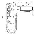
- FIG. 2is a cross-sectional view of another optical chamber that can be used with the subject invention having a bent path.
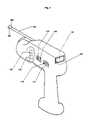
- FIG. 3shows an exterior perspective view of the novel portable detector housing.
- FIG. 4shows a cross-sectional interior view of the detector housing of FIG. 3 .
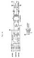
- FIG. 5shows a block diagram of the operational components used in the detector of FIGS. 3–4 .
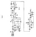
- FIGS. 6 a , 6 b , 6 c and 7 a and 7 bare schematics of the electronic circuitry within the novel detector.
- FIG. 8shows another optical chamber that can be used with the novel detector.
- FIG. 9shows a needle probe extension that can be used with the novel detector.
- aircan refer to a gaseous sample that may or may not contain any molecules of interest to the user.
- refrigerantcan refer to molecules of the gas with is of interest to the user, i.e., to be detected, but could in some applications be other refrigerants or other compounds of interest such as Methane, gasoline, and the like.
- the novel leak detectorcan be comprised of an infrared (IR) chamber, an air pump to draw in a sample, and electronics to process the signal.
- the IR chambercan contain an IR emitter, IR filters, an IR sensor, and a reaction tube where the sample air interacts with the IR beam.
- FIG. 1is a cross-sectional view of an optical chamber with a maize-like folded path to accomplish long-path behavior in a compact chamber that can be used with the subject invention.
- FIG. 2is a cross-sectional view of a bent optical chamber that can be used with the subject invention which can optimize long IR path length behavior by setting an optimum number of reflections by the optimized bend angle.
- the preferred embodiment of the chambercan be a gold plated chamber. A typical ray trace is shown in FIG. 2 .
- the portable gas leak detector of the inventioncan use an optical chamber to efficiently couple infrared (IR) energy from an optical source to an optical sensor, while maximizing IR interaction with the sample material gas.
- IRinfrared
- FIGS. 1–2are examples of optical chambers that can be used with the novel portable detector of the subject invention.
- FIG. 2shows a bent chamber which can optimize long IR path length behavior by setting an optimum number of reflections by the optimized bend angle.
- FIG. 2shows an optical chamber which can use a maize-like folded path to accomplish long-path behavior in a compact chamber. Both FIGS. 1 and 2 can allow the volume to be minimized to improve response and recovery times, and retain linear flow of the gas to improve gas clearing time. A description of the components will now be described.
- Component 11refers to hemispherical shape
- 26is a first filter
- 43is the infrared (IR) emitter
- 23is the sample air intake port
- 25is the gold plated housing.
- 28refers to a fastener such as a screw, and the like.
- 19refers to surface for holding the detector in place.
- 17refers to the cone shape for directing IR energy.
- 21refers to surface for holding the IR emitter.
- 28refers to the screw hole for assemblying the housing together.
- 27refers to the sample gas outlet to the pump (shown in FIG. 5).
- 29refers to plastic housing.
- 41refers to IR emitter.
- 43refers to seal for emitter.
- 47refers to the pyroelectric IR sensor. 49 refers to the seal for the sensor 47 .
- IR energypasses through the hemispherical shape 11 and is directed through thrombone shape into chamber passing through the first filter 26 that blocks energy from approximately 6 microns down.
- the energycontinues through the chamber and is absorbed by sample gas coming from inlet 27 continuing through the chamber through the cone shape directing into the sensor 47 .
- the sensorcan be fitted with a bandpath filter having a narrow bandwidth of approximately 8.48 to approximately 9.9 microns that allows energy to pass into the sensor 47 which can pass onto a personal computer for later processing and display, as needed.
- An airpump( 180 shown in FIG. 5 ) can pull air out of outlet port 27 .
- the IR emittercan be a resistive metal element that is heated via an electrical current to a temperature where its gray- or black-body radiation is maximized at the band of wavelengths where there is significant and unique interaction with the gas molecules being detected.
- an emitter with a positive temperature coefficient of resistanceimproves the performance of a battery-powered instrument. With battery voltage typically varying by approximately 20% or more from fully charged to almost discharged, the power consumed, temperature, and emission spectrum for a positive temp-co emitter will vary considerably less than approximately 20%.
- a thin platinum film on a silicon/silicon oxide, or an alumina surfaceis an example of a positive tempco resistance, whereas a NiCr resistively heated emitter generally has a small tempco, and so is more suited to an instrument powered from a regulated ac/dc power supply.
- the IRcan travel down a tube or beam-line where the air sample is drawn in to interact with the IR beam.
- This tubecan be plated with a material that is highly reflective, such as gold and the like, in order to conserve the signal from loss through absorption by the tube walls.
- the emitter end of the tubecan be a chamber shape to insure that most of the emitted IR gets directed down the interaction tube.
- One improvement for hand-held leak detectorsis to construct the IR chamber such that the emitter end is not aimed down the interaction tube, but instead is aimed at a sharp bend in the chamber that forces most of the IR energy to reflect of the walls of the interaction tube many times before reaching the detector.
- the zigzag path from the repeated reflectionscan create a longer IR path length, and increase the probability of absorption by a low concentration of Refrigerant, and thus increase signal strength and sensitivity to smaller concentrations. Any method to increase the effective IR path-length can be important to a portable leak-detector, where space is confined.
- the IR detectorcan include an optical filter “window” that is designed to only allow access to IR wavelengths that interact (get absorbed) strongly with the molecule being detected (e.g., Refrigerant). These wavelengths can be called “in-band.”
- An important feature to the hand-held leak-detectorcan be a second optical filter.
- the IR beamcan pass though an optical filter designed to remove as much “out-of-band” energy as possible, so the remaining IR beam is predominately of wavelengths that interact strongly with the gas of interest. This increases the signal-to-noise ratio of the system, and decreases the likelihood of false readings. Since most of the emitted blackbody radiation energy is typically out-of-band, the filter on the detector element would block it. However this excess energy, if absorbed at the detector filter, causes unwanted heating of the detector, which in itself increases the noise floor of the detector.
- some of the out-of-band spectrumcan be absorbed with compounds (water-vapor, carbon-dioxide, gasoline vapor, and the like) in the incoming air, and potentially be re-radiated in-band. Any significant variation in these extraneous compounds can cause variations in the energy seen by the detector, and can cause a false response.
- the sensor/detectorcan be a pyroelectric element.
- a version employed in this leak detectorcan include a pair of back-to-back piezo capacitor elements. The pair can be configured to cancel any direct temperature effects that they both experience. Only one element can be exposed to the incoming IR energy. If the IR energy changes (decreases due to absorption by Refrigerant molecules), the slight cooling changes the stress in the element, which changes the electrical potential on the element (pair), which in turn gets amplified by the integral JFET amplifier. The output voltage change on the JFET is then processed to interpret the signal.
- An air pumpcan be used to pull the air sample from the probe tip and through the IR chamber.
- the pumpcan be supplied from the battery though a voltage regulator and filter, which provides a more steady air flow, and prevents electrical noise from entering the detector electronics.
- the signal from the detector JFETcan be processed first by an ac-amplifier that is designed to block the dc level of the detector (which can vary widely), and pass only the differential of the detector output voltage, with a time constant tuned to the reaction of the detector, the delta-time of passing a leak, and the time to fill the IR chamber with an incoming air sample (this is a band-pass on the order of one Hz.)
- an ac-amplifierthat is designed to block the dc level of the detector (which can vary widely), and pass only the differential of the detector output voltage, with a time constant tuned to the reaction of the detector, the delta-time of passing a leak, and the time to fill the IR chamber with an incoming air sample (this is a band-pass on the order of one Hz.)
- the differential signalcan then be amplified and passed to an accumulator, which consists of a small-signal rectifier and integrator with a bleed-back time constant of a few seconds.
- an accumulatorwhich consists of a small-signal rectifier and integrator with a bleed-back time constant of a few seconds. This can allows a fleeting signal from a very small leak to be held long enough to be processed by subsequent electronics, and then expressed to the user with visual and/or audio alerts long enough to get his/her attention.
- the signal from the accumulatorgoes to another amplifier that provides the user with a zero control to null out any dc drift anywhere in the system, so that the electronics can be tuned to maximum sensitivity.
- the signalis then passed through a buffer and to a range-control amplifier designed to allow range changes with minimal upset to signal levels.
- the range controltypically provides a 1 ⁇ , 4 ⁇ , and 16 ⁇ increase in output sensitivity (L, M, S range) to the audio/visual electronics.
- a clampis provided to prevent large negative voltages from rebound due to very large signals, or due to the operator inadvertently setting the zero control too far the wrong way.
- the above analog signalcan then be presented to a simple digitizer that turns on LEDs in a bar-graph configuration.
- a single on-LED(such as a green light) shows the operator that the electronics is correctly zeroed, and ready for use. The larger the leak/signal, more LEDs light up.
- the digitizer ladderhas an exponential response to increase the resolution of more interesting signals, i.e. smaller leaks.
- the analog signalcan be processed uniquely in several ways at the audio VCO.
- a chirp rate of approximately 1 Hertzoccurs when the electronics is correctly zeroed. If the zero is even slightly too high, the chirp rate immediately jumps to approximately 2 Hertz. If the zero control is too low, the chirp is completely suppressed.
- the chirp rateincreases in proportion to the leak size. If the leak is very large, the chirp turns into a loud steady tone of approximately 3000 Hertz. Even the smallest leak detectable will cause the chirp rate to increase to a minimum of approximately 2 Hertz, which easily catches the attention of the operator.
- the audiotherefore is designed to allow full operation of the leak-detector with the operators eyes fixed on the probe tip, rather than the instruments display.
- a low battery warning LEDcan be provided.
- the LEDis set to go on to warn the operator that approximately 80% of the battery's charge is depleted, so that he/she is more likely to get the unit recharged while convenient, and to avoid deep discharges that can affect the overall life of the NMH battery.
- the controls for the devicecan be a Power-on, audio enable, zero, and range.
- a charging status LEDcan be activated when the battery charger supply is plugged into the leak detector. The charging circuit lights this LED brightly when the battery is low, and then dims the LED as the battery nears fill charge.
- the detector outputgoes to an ac amplifier with a band-pass of approximately 1 Hz. Since no continuous signal is generated, and the IR emitter is not pulsed, the function of this ac amplifier is to produce a signal that represents a change in the dc level from the detector.
- Other electronicscan do this function as well: taking this differential can be done digitally as well as in analog.
- another embodimentcould be as follows: a minimum amount of analog amplification of the detector, and then an A/D converter, followed by digital processing to determine signal speed and amplitude, and then to generate an output signal that holds and decays at a rate that provides maximum indication to the human user.
- the functionalitycould also be done with an analog switched-signal or sampling mode.
- FIG. 3shows an exterior perspective view of the novel portable detector housing 1 .
- FIG. 4shows a cross-sectional interior view of the detector housing 1 of FIG. 3 .
- the housing 1can be formed from two half shells formed from ABS plastic, and the like, and can be durable and waterproofed in construction.
- portable detector housing be L-shapedcan have a height H of approximately 24.87 centimeters (approximately 9.79 inches) along the hand grip section G to the sensor section S, and a length L, along the sensor section S of approximately 10.322 inches, and can have an overall weight of approximately 31 ounces.
- a rechargeable battery 150 with battery connector 152can be located inside the grip section G between a bottom body portion 151 and a top body portion 154 . Exterior power cords (not shown) can be attached to an exterior side charger port 130 to charge the battery 150 .
- a charger lamp 135can light up to varying degrees to indicate when the battery 150 has been sufficiently charged.
- Facing rearward from the upper sensor section Scan be LED display screen 140 , with power on/off toggle switch 110 and audio on/off toggle switch 115 on the side of the sensor section S above the grip section G.
- Rotatable type controls 120 , 125(such as but not limited to rheostats, rotating switches and potentiometers, and the like) on the side of sensor section S can be used to respectively adjust sensitivity settings and zero settings of the device 1 .
- On the outside of the device 1can be an extendable probe 160 which will be explained later in reference to FIG. 9 .
- Other interior componentswhich will be described in more detail later include circuit board 172 , board bracket 174 for mounting the circuit board 174 , air pump 180 , optical bench 185 , sample in tube 192 , sample out tube 194 and strain relief 195 .
- FIG. 5shows a block diagram of the operational components used in the detector of FIGS. 3–4 .
- FIG. 5shows a block diagram of a preferred embodiment of the Leak-Detector system.
- the portable Hand-Held unitis powered by a rechargeable battery 150 , such as a Nickel-Metal-Hydride pack that recharges well even if the battery is not fully discharged.
- the battery 150can directly power electronics that are not noise sensitive, such as digital, LEDs and the audio.
- the analog circuitrycan be powered via a DC/DC converter 205 and filter(s) 210 to isolate any electrical noise.
- a low-battery detector 215can continuously monitors the battery voltage, and warns the user with an LED 220 whose brightness and dimness varies when the battery 150 will soon require a recharge. With the proper selection of battery 150 and Infrared (IR) emitter 230 , the emitter 230 can be driven directly from the battery 150 . The emitted IR energy 232 must pass through one or more optical filters 235 that select and optimize the IR wavelengths that are most reactive with the species of gas that is being detected.
- An air pump 180pulls air in the direction of arrow P continuously from the probe tip 160 , and through the IR reaction chamber 240 . The pump 180 can be driven by a voltage regulator 182 that keeps the flow-rate independent of battery charge, and also isolates pump electrical noise from the rest of the system.
- the probe tip 160can be a pliable type tip formed from pliable type stainless steel spring material and the like, having a length of between a few centimeters (few inches) and approximately 30.48 centimeters (approximately 12 inches), and can include an enlarged air intake end 162 having a separate filter inside, which can be used to restrict fluids and liquids from entering the probe tip 160 .
- the IR beam 232can pass through another optical filter 237 that is part of the IR sensor assembly.
- This filtercan further improve IR signal to noise ratio and helps isolate the sensor 245 from any thermal changes due to changes in probed air temperature.
- a third filter 355 or window, shown in the embodiment of FIG. 8can be attached as a “lid” to the emitter element. This third filter 355 also improves the signal to noise ratio by increasing the in-band energy, and by isolating the chamber 240 from air convection-currents at the emitter, which can create IR “noise” due to handling motion.
- the IR sensor 245can include an integral amplifier, such as a JFET follower inside the sensor component.
- the IR sensor 245 outputcan be amplified first by a tuned amplifier 250 with a band-pass peak response optimized to approximately 1 to approximately 3 Hertz. Any higher frequencies can be rejected as electrical noise, and slower signals can be rejected as irrelevant environmental changes.
- the signalnext passes through a series of analog amplifiers 255 designed to detect a possibly very small signal (small leak) from the noise of the sensor 245 .
- these amplifiers 255can favor detection of increases in gas concentration (i.e., dropping IR energy at the sensor 245 ), accumulate and temporarily hold the signal for the subsequent electronics to process and make alarm (LED display 280 ( 140 FIG. 3 ) and speaker 290 ) decisions.
- a zero control 257( 125 FIG. 3 ) can be provided to set the steady-state “ready” condition.
- a range switch 259120 FIG. 2 ) can allow the user to decrease system gain, and works independently of the zero control, i.e., the range can be switched “on the fly” with no settling time penalty.
- the analog output signalcan be fed to a simple A/D digitizer 260 and a chirp generator 270 .
- the digitizer 260is preferably not linear, but is somewhat exponential in response to favor more signal perception resolution with smaller leaks, while avoiding over-running the LED display 280 with moderate-sized leaks.
- the chirp generator 270can modulate the tone of the audio (piezo) speaker 290 according to the size of the leak detected.
- the chirpIn the steady-state condition (warmed up, but not yet being used) the chirp can be set at approximately 1 beep per second, as an easily recognized condition for the user to know the instrument is properly zeroed and ready to use. (The IR emitter and IR sensor take about one or two minutes to “warm up”.) If the zero 257 is set too low, the detector 100 will be less sensitive to leaks, and so the green LED will be off, and the speaker 290 will be silent.
- the digitizer 260enables ( 264 ) the 1 Hz chirp rate. Upon detection of a small leak, the digitizer 260 can immediately shift ( 264 ) the chirp generator 270 to a readily-noticed 2 Hz chirp rate. If the leak is larger, the chirp rate can be increased in proportion to the size of the leak detected.
- FIGS. 6 and 7are schematics of the electronic circuitry within the novel detector and correlate to the block diagram of FIG. 5 .
- battery powerenters at J 2 and directly powers the IR emitter and the 12 volt noncritical circuitry (e.g., digital circuits on FIG. 7 ).
- the batterydrives the air-pump through regulator U 10 which sets the air-flow rate.
- the batteryalso powers the IR sensor and analog circuitry in FIG. 6 through a dc/dc converter and LC filters on both +12 and ⁇ 12 volt rails.
- a valid leak signalstarts at the IR sensor at J 1 (upper left of FIG. 6 ).
- a band-pass amplifieris formed by Integrated Circuit (IC) U 6 -A and associated components.
- ICIntegrated Circuit
- This amplifierrejects the dc level and drift in the sensor, as well as higher frequency noise.
- the signalis further amplified and detected by IC U 1 -A and U 1 -B, and associated diodes and components.
- the circuit at IC U 6 -Bprovides the important signal “accumulator” function.
- R 26insures that D 6 is always switched slightly “on” and ready to pass a small signal to C 14 where it is temporarily held for further processing. This allows rapid detection of even a small leak, while accumulating more “signal” as the internally compensated IR sensor rebounds from a stronger signal.
- the detected (accumulator) signalis monitored by IC U 8 -A which subtracts off the dc level produced by the previous stage, provides a factory-adjustable gain at R 31 , and a user-adjustable “zero” at “POT” R 46 .
- IC U 8 -Bis a follower to isolate the zero and gain adjust stage from the range switch stage at IC U 7 -B.
- the Range switchprovides the user with 3 sensitivity levels labeled at “Large,” “Medium,” and “Small” leaks.
- the final analog outputis clamped by low forward voltage diode D 7 to keep the output form going much below zero volts in spite of wrong control settings or misuse.
- the final analog outputis passed to the digital circuit at the upper right corner of FIG. 7 .
- this analog signalis compared with a non-linear resistive voltage divider via ICs U 4 and U 5 to provide the desired digital representation of the leak size on the LED display.
- D 13is a green LED that signals proper zero setting on a warmed up instrument at a steady-state condition (prior to detecting a leak).
- D 12 to D 4form a bar-graph display of relative leak sizes.
- the sound generatorconsists of a chirp (pulse) generator at U 9 , a tone generator (e.g., 3000 Hz, which can be built into the Piezo speaker), an enable function, and a chirp rate shift function.
- the enable functionis formed by Q 2 , which suppresses chirp output until the green LED D 13 is on.
- the shift functionis formed by Q 2 to double the chirp rate (jump from approximately 1 Hz to approximately 2 Hz), as soon as the smallest leak is detected.
- the chirp rateis increased further with increasing analog (leak size) signal at U 9 via U 7 -A.
- low battery detectionis provided by U 4 -D that compares the battery voltage with a precision voltage reference, through a divider set to trigger at the voltage at which a 12 volt NMH battery pack is about 90% discharged. This gives the user about 20–30 minutes warning that a recharge is needed very soon. Of course the warning could be set for earlier or later.
- the battery charging functionis not represented on FIGS. 6–7 . Charging can be provided through a current-sensing resistor that allows the charge LED to dim as the battery nears full charge, even using a low-cost non-regulated charger.
- the Industrial versions of the leak-detectorcan be very similar to FIGS. 6–7 , except that the battery and charging functions are replaced by a 12.6 volt power supply, plus a larger air-pump regulator driving a long-life pump motor, and various “heavy duty” controls can be used.
- FIG. 8shows another optical chamber 300 that can be used with the novel detector.
- the signal to noise (S/N) ratiocan be improved in the leak detector with a tandem optical bandpass filter configuration.
- Bandpass filter 1 , 315can pass in-band IR energy (approximately 8 to approximately 10 microns), but absorb higher-energy photons (less than approximately 8 microns), heats up, and re-emits this energy at a cooler temperature than the emitter.
- a substantial fraction of this secondary emissioncan be in the approximately 8 to approximately 10 micron band, and these photons can also pass through bandpass filter 2 , 320 (an approximately 8 to approximately 10 micron filter) as well.
- IR sensor 310can be a pair of parallel piezo capacitor elements that are coated optical black, Lithium Tanalate, and the like. Sample port 330 , pump 340 , IR chamber 305 and the other components conform to the similar described components previously described above. An additional filter 355 previously described can also be used.
- the novel leak detectorwas able to operate in various temperature conditions ranging from approximately 32 to approximately 104 degrees F.
- the battery life of the detectorlasted between approximately 4 to approximately 5 hours before needing to be recharged, and the sensor life was measured to have a life span of up to approximately 84 months (approximately 7 years).
- Response time for measuring leak contaminants such as refrigerantwas within approximately 0.85 seconds of the time the leak detector was placed adjacent to the leak.
- Settings on the deviceallowed for at least three different setting positions. S covers small leaks of approximately 0.1 to approximately 1 oz per year.
- Mcovered medium leaks of approximately 0.4 to approximately 4 oz/yr.
- Lcovered large leaks of approximately 1.6 to approximately 16 oz/yr.
- FIG. 9shows an extra needle probe extension 460 that can be used with the novel detector 100 shown in FIG. 3 .
- the needle probe extension 460can be substantially tubular in configuration with a length of approximately 22.86 centimeters (approximately 9 inches), an outer diameter of approximately 0.3175 centimeters (approximately 1 ⁇ 8 of an inch) and an inside bore diameter of approximately 0.15875 centimeters (approximately 1/16 of an inch).
- Intake holes 467can be set back from the end of the probe 468 to help prevent clogging.
- Opposite end 462can include a threaded exterior or threaded interior surface to threadably attach to end 162 of the probe extension with an interior filter 164 shown in FIG. 3 .
- Probe extension 460can be formed from a pliable and strong material such as soft brass tubing which allows the probe extension to bend up to approximately 60 degrees without breaking apart, and allows it to be inserted into tight and narrow spaces for leak detection applications. Additional probe extensions up to an additional 30.48 centimeters (12 inches) can also be attached to the leak detector.
- the novel detectorcan be used to detect various types of compounds such as gases and the like.
- Table 1is a partial list of such compound materials that can be detected.
- HCFCHydrogenated Chorofluro carbon compounds, such as R-22 2.
- HFCFluorocarbon compounds, such as R-134a 3.
- CFCChorofluoro carbon compounds, such as R 12 4.
- Refrigerant blends5. Propane 6. Methane 7. Gasoline 8. Ammonia 9. Acetone 10. Benzene 11. Bromine 12. Carbon dioxide 13. Carbon Monoxide 14. Chlorine 15. Fluorine 16. Hydrogen Sulfide 17. Isobutyl Alcohol 18. Isopropyl Ether 19. Pentane 20. Sulfur Dioxide 21. Sulfur Hexafluoride 22. Trichloroethane 23. Vinyl Acetate 24. Vinyl Bromide 25. Xylenes
- the leak detector deviceis shown using a chargeable battery, the detector can easily be operable to work off a power cord, and the like.
- the detector devicecan be powered continuously from an AC/DC supply module that plugs into 115 Vac or 230 Vac.
Landscapes
- Physics & Mathematics (AREA)
- General Physics & Mathematics (AREA)
- General Health & Medical Sciences (AREA)
- Chemical & Material Sciences (AREA)
- Analytical Chemistry (AREA)
- Biochemistry (AREA)
- Life Sciences & Earth Sciences (AREA)
- Health & Medical Sciences (AREA)
- Immunology (AREA)
- Pathology (AREA)
- Spectroscopy & Molecular Physics (AREA)
- Investigating Or Analysing Materials By Optical Means (AREA)
- Examining Or Testing Airtightness (AREA)
Abstract
Description
| TABLE 1 |
| 1. | HCFC—Hydrogenated Chorofluro carbon compounds, such as R-22 |
| 2. | HFC—Fluorocarbon compounds, such as R- |
| 3. | CFC—Chorofluoro carbon compounds, such as |
| 4. | Refrigerant blends |
| 5. | |
| 6. | Methane |
| 7. | |
| 8. | |
| 9. | |
| 10. | |
| 11. | |
| 12. | |
| 13. | Carbon Monoxide |
| 14. | |
| 15. | Fluorine |
| 16. | |
| 17. | |
| 18. | |
| 19. | Pentane |
| 20. | |
| 21. | Sulfur Hexafluoride |
| 22. | |
| 23. | Vinyl Acetate |
| 24. | |
| 25. | Xylenes |
Claims (8)
Priority Applications (1)
| Application Number | Priority Date | Filing Date | Title |
|---|---|---|---|
| US10/899,182US7022993B1 (en) | 2001-05-04 | 2004-07-26 | Infrared leak detector |
Applications Claiming Priority (3)
| Application Number | Priority Date | Filing Date | Title |
|---|---|---|---|
| US28885701P | 2001-05-04 | 2001-05-04 | |
| US10/138,399US6791088B1 (en) | 2001-05-04 | 2002-05-03 | Infrared leak detector |
| US10/899,182US7022993B1 (en) | 2001-05-04 | 2004-07-26 | Infrared leak detector |
Related Parent Applications (1)
| Application Number | Title | Priority Date | Filing Date |
|---|---|---|---|
| US10/138,399DivisionUS6791088B1 (en) | 2001-05-04 | 2002-05-03 | Infrared leak detector |
Publications (1)
| Publication Number | Publication Date |
|---|---|
| US7022993B1true US7022993B1 (en) | 2006-04-04 |
Family
ID=32929939
Family Applications (2)
| Application Number | Title | Priority Date | Filing Date |
|---|---|---|---|
| US10/138,399Expired - Fee RelatedUS6791088B1 (en) | 2001-05-04 | 2002-05-03 | Infrared leak detector |
| US10/899,182Expired - LifetimeUS7022993B1 (en) | 2001-05-04 | 2004-07-26 | Infrared leak detector |
Family Applications Before (1)
| Application Number | Title | Priority Date | Filing Date |
|---|---|---|---|
| US10/138,399Expired - Fee RelatedUS6791088B1 (en) | 2001-05-04 | 2002-05-03 | Infrared leak detector |
Country Status (1)
| Country | Link |
|---|---|
| US (2) | US6791088B1 (en) |
Cited By (31)
| Publication number | Priority date | Publication date | Assignee | Title |
|---|---|---|---|---|
| US20050230628A1 (en)* | 2002-08-21 | 2005-10-20 | Tadaaki Hirai | Radiation detector |
| US20080069177A1 (en)* | 2006-09-15 | 2008-03-20 | Minor Barbara H | Method of detecting leaks of fluoroolefin compositions and sensors used therefor |
| US20080233504A1 (en)* | 2007-03-20 | 2008-09-25 | Syntronics L.L.C. | Corona detection device |
| US20080277586A1 (en)* | 2007-05-07 | 2008-11-13 | Dennis Cardinale | Low-Power Fast Infrared Gas Sensor, Hand Held Gas Leak Detector, and Gas Monitor Utilizing Absorptive-Photo-Acoustic Detection |
| US20080295580A1 (en)* | 2006-09-15 | 2008-12-04 | Barbara Haviland Minor | Method of determining the components of a fluoroolefin composition, method of recharging a fluid system in response thereto, and sensors used therefor |
| US20090025298A1 (en)* | 2005-11-18 | 2009-01-29 | Ray Hawkins | Device for monitoring motion of a movable closure |
| US20090120165A1 (en)* | 2005-07-20 | 2009-05-14 | Peter Lang | Sampling Leak Detector |
| US20100284570A1 (en)* | 2008-01-08 | 2010-11-11 | Ernest Grimberg | System and method for gas leakage detection |
| CN102183795A (en)* | 2011-02-28 | 2011-09-14 | 中北大学 | Target detection system and method based on dynamic utilization of pyroelectric infrared sensor |
| US20110279952A1 (en)* | 2008-10-14 | 2011-11-17 | Gabor Sonyey | Portable Vibration Monitoring Device |
| US20130094535A1 (en)* | 2011-10-17 | 2013-04-18 | Progress Rail Services Corporation | Device for testing a sensor of train undercarriage temperatures |
| US20130340501A1 (en)* | 2012-06-21 | 2013-12-26 | Ryan Val Peacock | Apparatus for testing a filter |
| US8653461B1 (en) | 2007-03-23 | 2014-02-18 | Flir Systems, Inc. | Thermography camera tuned to detect absorption of infrared radiation in a selected spectral bandwidth |
| US8659664B2 (en) | 2007-03-23 | 2014-02-25 | Flir Systems, Inc. | Thermography camera configured for leak detection |
| CN103765199A (en)* | 2011-08-27 | 2014-04-30 | 英福康有限责任公司 | Device and method for identifying refrigerants |
| US20150028209A1 (en)* | 2013-07-26 | 2015-01-29 | Rey P. Harju | Refrigerant Gas Leak Detector |
| US8947249B1 (en)* | 2009-03-26 | 2015-02-03 | Safezone Safety Systems, LLC | Apparatus and method for conducting hot work |
| US9506804B2 (en) | 2013-01-17 | 2016-11-29 | Detector Electronics Corporation | Open path gas detector |
| US10234354B2 (en) | 2014-03-28 | 2019-03-19 | Intelliview Technologies Inc. | Leak detection |
| US10302521B2 (en) | 2017-10-30 | 2019-05-28 | Robert Dean Hoffman | System, method, and tool for locating refrigerant leaks in air conditioning systems and the like |
| US10337949B2 (en) | 2016-02-15 | 2019-07-02 | Kane Usa, Inc. | Leak detector |
| US10373470B2 (en) | 2013-04-29 | 2019-08-06 | Intelliview Technologies, Inc. | Object detection |
| US10518301B1 (en) | 2015-12-18 | 2019-12-31 | SafeZone Safety Systems, L.L.C. | Isolation enclosure and method for conducting hot work |
| CN111189975A (en)* | 2020-01-08 | 2020-05-22 | 北京航天试验技术研究所 | Gas leakage positioning device and positioning method |
| US10943357B2 (en) | 2014-08-19 | 2021-03-09 | Intelliview Technologies Inc. | Video based indoor leak detection |
| WO2023006516A1 (en)* | 2021-07-30 | 2023-02-02 | Binder Gmbh | Apparatus for measuring the methane content of a gas |
| US11604019B2 (en) | 2020-08-13 | 2023-03-14 | Emerson Climate Technologies, Inc. | Systems and methods for leak detection and refrigerant charging |
| EP4163622A1 (en)* | 2021-10-11 | 2023-04-12 | Jiangsu Jingchuang Electronics Co., Ltd | Non-modulated infrared sensor for hand-held halogen leak detector and its quantitative detection method |
| US11768151B2 (en) | 2019-11-22 | 2023-09-26 | Abb Schweiz Ag | Systems and methods for locating sources of fugitive gas emissions |
| US11802700B2 (en) | 2017-04-06 | 2023-10-31 | Carrier Corporation | Moderate-to-low global warming potential value refrigerant leak detection |
| US11927354B2 (en) | 2018-07-06 | 2024-03-12 | Carrier Corporation | Method and system for flammable gas detection |
Families Citing this family (30)
| Publication number | Priority date | Publication date | Assignee | Title |
|---|---|---|---|---|
| US6791088B1 (en) | 2001-05-04 | 2004-09-14 | Twin Rivers Engineering, Inc. | Infrared leak detector |
| US8418530B1 (en) | 2005-04-08 | 2013-04-16 | Mainstream Engineering Corporation | Compositions and methods for detecting leaks in HVAC/R systems |
| US7851758B1 (en) | 2005-09-29 | 2010-12-14 | Flir Systems, Inc. | Portable multi-function inspection systems and methods |
| CN101821635B (en) | 2007-08-03 | 2017-07-28 | 弗莱尔系统公司 | Wireless remote detector systems and method |
| US20090066525A1 (en)* | 2007-08-28 | 2009-03-12 | Thomas Walsh | Smoke meter and locator |
| US8779362B1 (en) | 2012-04-16 | 2014-07-15 | Ted J. Amundsen | Infrared acid detector and method |
| EP3069114B1 (en)* | 2013-11-11 | 2024-04-03 | Amphenol Thermometrics, Inc. | Optical gas sensor |
| US9442011B2 (en) | 2014-06-23 | 2016-09-13 | Exxonmobil Upstream Research Company | Methods for calibrating a multiple detector system |
| US9471969B2 (en) | 2014-06-23 | 2016-10-18 | Exxonmobil Upstream Research Company | Methods for differential image quality enhancement for a multiple detector system, systems and use thereof |
| US9501827B2 (en) | 2014-06-23 | 2016-11-22 | Exxonmobil Upstream Research Company | Methods and systems for detecting a chemical species |
| EP3158321A1 (en) | 2014-06-23 | 2017-04-26 | Exxonmobil Upstream Research Company | Systems for detecting a chemical species and use thereof |
| US9684312B1 (en) | 2014-11-22 | 2017-06-20 | Orbit Irrigation Products, Inc. | Resource consumption measurement system and method |
| CN106769977A (en)* | 2016-12-30 | 2017-05-31 | 武汉市欧睿科技有限公司 | A kind of hand-held high-precision gas quantitative leak detector |
| CN107192215B (en)* | 2017-04-21 | 2020-08-28 | 青岛海尔股份有限公司 | Refrigerator refrigerant leakage monitoring device, control method and control system thereof |
| US10295457B1 (en) | 2017-06-13 | 2019-05-21 | Larry Ocheltree | Airplane cabin air quality monitoring system |
| CN108332913B (en)* | 2018-02-02 | 2020-03-27 | 国网山东省电力公司潍坊供电公司 | SF6 infrared leak detection aids |
| US10900857B2 (en)* | 2018-06-06 | 2021-01-26 | Ford Global Technologies, Llc | Methods and systems for fluid leak determination |
| CN109739235B (en)* | 2019-01-03 | 2020-06-19 | 西安交通大学 | Automatic tracking method for leaked gas of female mosquito-imitating mobile sensor |
| CN110426167B (en)* | 2019-08-26 | 2025-02-18 | 优必得石油设备(苏州)有限公司 | Infrared optical recognition device and method |
| US11231198B2 (en) | 2019-09-05 | 2022-01-25 | Trane International Inc. | Systems and methods for refrigerant leak detection in a climate control system |
| US11732916B2 (en) | 2020-06-08 | 2023-08-22 | Emerson Climate Technologies, Inc. | Refrigeration leak detection |
| US11359846B2 (en) | 2020-07-06 | 2022-06-14 | Emerson Climate Technologies, Inc. | Refrigeration system leak detection |
| US11885516B2 (en) | 2020-08-07 | 2024-01-30 | Copeland Lp | Refrigeration leak detection |
| US11754324B2 (en) | 2020-09-14 | 2023-09-12 | Copeland Lp | Refrigerant isolation using a reversing valve |
| US11609032B2 (en) | 2020-10-22 | 2023-03-21 | Emerson Climate Technologies, Inc. | Refrigerant leak sensor measurement adjustment systems and methods |
| USD943441S1 (en)* | 2020-11-06 | 2022-02-15 | Xuzhou Sinotemp Co., Ltd. | Halogen leak detector |
| USD946436S1 (en)* | 2020-11-13 | 2022-03-22 | Fieldpiece Instruments, Inc. | Leak detector |
| US12196462B2 (en) | 2021-03-23 | 2025-01-14 | Copeland Lp | Heat-pump system with multiway valve |
| US11940188B2 (en) | 2021-03-23 | 2024-03-26 | Copeland Lp | Hybrid heat-pump system |
| US12117191B2 (en) | 2022-06-24 | 2024-10-15 | Trane International Inc. | Climate control system with improved leak detector |
Citations (14)
| Publication number | Priority date | Publication date | Assignee | Title |
|---|---|---|---|---|
| US4489239A (en)* | 1982-09-24 | 1984-12-18 | The United States Of America As Represented By The Administrator Of The National Aeronautics And Space Administration | Portable remote laser sensor for methane leak detection |
| US4825079A (en)* | 1986-05-30 | 1989-04-25 | Sumitomo Metal Company Limited | Pyroelectric infrared detector |
| US4958076A (en)* | 1989-02-10 | 1990-09-18 | Gas Research Institute | Selective natural gas detecting apparatus |
| US5156042A (en)* | 1987-07-17 | 1992-10-20 | Proeco, Inc. | Leak detector |
| US5228329A (en)* | 1991-12-27 | 1993-07-20 | Conservation Devices, Inc. | Leak detector for fluid distribution systems serving intermittent loads |
| US5264833A (en)* | 1991-06-28 | 1993-11-23 | Edward Jeffers | Automatic leak detector |
| US5497003A (en)* | 1995-02-15 | 1996-03-05 | Servo Corporation Of America | Pyroelectric detector array with optical filter elements |
| US5889199A (en)* | 1997-05-13 | 1999-03-30 | Jaesent Inc. | Portable leak detector |
| US20020007663A1 (en)* | 1997-01-24 | 2002-01-24 | Mainstream Engineering Corporation | Method of introducing an in situant into a vapor compression system, especially useful for leak detection, as well as an apparatus for leak detection and a composition useful for leak detection |
| US20020033759A1 (en)* | 2000-02-25 | 2002-03-21 | The Linjan Corp., Inc. | Water leak detection and suppression |
| US6362741B1 (en)* | 2001-06-06 | 2002-03-26 | Bacharach, Inc. | Leak detector |
| US6509567B2 (en)* | 2000-05-30 | 2003-01-21 | Gaz De France | Method and apparatus for detecting gases |
| US20030086091A1 (en)* | 2001-11-08 | 2003-05-08 | Michele Hinnrichs | Gas leak detector |
| US6791088B1 (en) | 2001-05-04 | 2004-09-14 | Twin Rivers Engineering, Inc. | Infrared leak detector |
- 2002
- 2002-05-03USUS10/138,399patent/US6791088B1/ennot_activeExpired - Fee Related
- 2004
- 2004-07-26USUS10/899,182patent/US7022993B1/ennot_activeExpired - Lifetime
Patent Citations (14)
| Publication number | Priority date | Publication date | Assignee | Title |
|---|---|---|---|---|
| US4489239A (en)* | 1982-09-24 | 1984-12-18 | The United States Of America As Represented By The Administrator Of The National Aeronautics And Space Administration | Portable remote laser sensor for methane leak detection |
| US4825079A (en)* | 1986-05-30 | 1989-04-25 | Sumitomo Metal Company Limited | Pyroelectric infrared detector |
| US5156042A (en)* | 1987-07-17 | 1992-10-20 | Proeco, Inc. | Leak detector |
| US4958076A (en)* | 1989-02-10 | 1990-09-18 | Gas Research Institute | Selective natural gas detecting apparatus |
| US5264833A (en)* | 1991-06-28 | 1993-11-23 | Edward Jeffers | Automatic leak detector |
| US5228329A (en)* | 1991-12-27 | 1993-07-20 | Conservation Devices, Inc. | Leak detector for fluid distribution systems serving intermittent loads |
| US5497003A (en)* | 1995-02-15 | 1996-03-05 | Servo Corporation Of America | Pyroelectric detector array with optical filter elements |
| US20020007663A1 (en)* | 1997-01-24 | 2002-01-24 | Mainstream Engineering Corporation | Method of introducing an in situant into a vapor compression system, especially useful for leak detection, as well as an apparatus for leak detection and a composition useful for leak detection |
| US5889199A (en)* | 1997-05-13 | 1999-03-30 | Jaesent Inc. | Portable leak detector |
| US20020033759A1 (en)* | 2000-02-25 | 2002-03-21 | The Linjan Corp., Inc. | Water leak detection and suppression |
| US6509567B2 (en)* | 2000-05-30 | 2003-01-21 | Gaz De France | Method and apparatus for detecting gases |
| US6791088B1 (en) | 2001-05-04 | 2004-09-14 | Twin Rivers Engineering, Inc. | Infrared leak detector |
| US6362741B1 (en)* | 2001-06-06 | 2002-03-26 | Bacharach, Inc. | Leak detector |
| US20030086091A1 (en)* | 2001-11-08 | 2003-05-08 | Michele Hinnrichs | Gas leak detector |
Cited By (48)
| Publication number | Priority date | Publication date | Assignee | Title |
|---|---|---|---|---|
| US7217929B2 (en)* | 2002-08-21 | 2007-05-15 | Hamamatsu Photonics K.K. | Radiation detector |
| US20050230628A1 (en)* | 2002-08-21 | 2005-10-20 | Tadaaki Hirai | Radiation detector |
| US20090120165A1 (en)* | 2005-07-20 | 2009-05-14 | Peter Lang | Sampling Leak Detector |
| US20090025298A1 (en)* | 2005-11-18 | 2009-01-29 | Ray Hawkins | Device for monitoring motion of a movable closure |
| US8037922B2 (en)* | 2005-11-18 | 2011-10-18 | Automatic Technology (Australia) Pty Ltd | Device for monitoring motion of a movable closure |
| US8058070B2 (en)* | 2006-09-15 | 2011-11-15 | E. I. Du Pont De Nemours And Company | Method of determining the components of a fluoroolefin composition, method of recharging a fluid system in response thereto, and sensors used therefor |
| US20080295580A1 (en)* | 2006-09-15 | 2008-12-04 | Barbara Haviland Minor | Method of determining the components of a fluoroolefin composition, method of recharging a fluid system in response thereto, and sensors used therefor |
| US20080069177A1 (en)* | 2006-09-15 | 2008-03-20 | Minor Barbara H | Method of detecting leaks of fluoroolefin compositions and sensors used therefor |
| US8070355B2 (en)* | 2006-09-15 | 2011-12-06 | E. I. Du Pont De Nemours And Company | Method of detecting leaks of fluoroolefin compositions and sensors used therefor |
| US7732782B2 (en)* | 2007-03-20 | 2010-06-08 | Syntronics L.L.C. | Corona detection device |
| US20080233504A1 (en)* | 2007-03-20 | 2008-09-25 | Syntronics L.L.C. | Corona detection device |
| US9276161B2 (en) | 2007-03-23 | 2016-03-01 | Flir Systems, Inc. | Thermography camera tuned to detect absorption of infrared radiation in a selected spectral bandwidth |
| US9635284B2 (en) | 2007-03-23 | 2017-04-25 | Flir Systems, Inc. | Thermography camera tuned to detect absorption of infrared radiation in a selected spectral bandwidth |
| US8659664B2 (en) | 2007-03-23 | 2014-02-25 | Flir Systems, Inc. | Thermography camera configured for leak detection |
| US8653461B1 (en) | 2007-03-23 | 2014-02-18 | Flir Systems, Inc. | Thermography camera tuned to detect absorption of infrared radiation in a selected spectral bandwidth |
| US20080277586A1 (en)* | 2007-05-07 | 2008-11-13 | Dennis Cardinale | Low-Power Fast Infrared Gas Sensor, Hand Held Gas Leak Detector, and Gas Monitor Utilizing Absorptive-Photo-Acoustic Detection |
| US8548271B2 (en) | 2008-01-08 | 2013-10-01 | Opgal Optronic Industries Ltd. | System and method for gas leakage detection |
| US20100284570A1 (en)* | 2008-01-08 | 2010-11-11 | Ernest Grimberg | System and method for gas leakage detection |
| US20110279952A1 (en)* | 2008-10-14 | 2011-11-17 | Gabor Sonyey | Portable Vibration Monitoring Device |
| US8800374B2 (en)* | 2008-10-14 | 2014-08-12 | Aktiebolaget Skf | Portable vibration monitoring device |
| US10989477B2 (en) | 2009-03-26 | 2021-04-27 | Safezone Safety Systems, LLC | Apparatus and method for conducting hot work |
| US8947249B1 (en)* | 2009-03-26 | 2015-02-03 | Safezone Safety Systems, LLC | Apparatus and method for conducting hot work |
| CN102183795B (en)* | 2011-02-28 | 2013-12-25 | 中北大学 | Target detection system and method based on dynamic utilization of pyroelectric infrared sensor |
| CN102183795A (en)* | 2011-02-28 | 2011-09-14 | 中北大学 | Target detection system and method based on dynamic utilization of pyroelectric infrared sensor |
| US10031075B2 (en) | 2011-08-27 | 2018-07-24 | Inficon Gmbh | Device and method for identifying refrigerants |
| CN103765199A (en)* | 2011-08-27 | 2014-04-30 | 英福康有限责任公司 | Device and method for identifying refrigerants |
| CN103765199B (en)* | 2011-08-27 | 2016-09-21 | 英福康有限责任公司 | For identifying the apparatus and method of cold-producing medium |
| US8944677B2 (en)* | 2011-10-17 | 2015-02-03 | Progress Rail Services Corp | Device for testing a sensor of train undercarriage temperatures |
| US9423305B2 (en) | 2011-10-17 | 2016-08-23 | Progress Rail Services Corporation | Device for testing a sensor of train undercarriage temperatures |
| US20130094535A1 (en)* | 2011-10-17 | 2013-04-18 | Progress Rail Services Corporation | Device for testing a sensor of train undercarriage temperatures |
| US9772271B2 (en)* | 2012-06-21 | 2017-09-26 | Hamilton Associates, Inc. | Apparatus for testing a filter |
| US20130340501A1 (en)* | 2012-06-21 | 2013-12-26 | Ryan Val Peacock | Apparatus for testing a filter |
| US9506804B2 (en) | 2013-01-17 | 2016-11-29 | Detector Electronics Corporation | Open path gas detector |
| US10373470B2 (en) | 2013-04-29 | 2019-08-06 | Intelliview Technologies, Inc. | Object detection |
| US20150028209A1 (en)* | 2013-07-26 | 2015-01-29 | Rey P. Harju | Refrigerant Gas Leak Detector |
| US10234354B2 (en) | 2014-03-28 | 2019-03-19 | Intelliview Technologies Inc. | Leak detection |
| US10943357B2 (en) | 2014-08-19 | 2021-03-09 | Intelliview Technologies Inc. | Video based indoor leak detection |
| US10518301B1 (en) | 2015-12-18 | 2019-12-31 | SafeZone Safety Systems, L.L.C. | Isolation enclosure and method for conducting hot work |
| US10337949B2 (en) | 2016-02-15 | 2019-07-02 | Kane Usa, Inc. | Leak detector |
| US11802700B2 (en) | 2017-04-06 | 2023-10-31 | Carrier Corporation | Moderate-to-low global warming potential value refrigerant leak detection |
| US10302521B2 (en) | 2017-10-30 | 2019-05-28 | Robert Dean Hoffman | System, method, and tool for locating refrigerant leaks in air conditioning systems and the like |
| US11927354B2 (en) | 2018-07-06 | 2024-03-12 | Carrier Corporation | Method and system for flammable gas detection |
| US11768151B2 (en) | 2019-11-22 | 2023-09-26 | Abb Schweiz Ag | Systems and methods for locating sources of fugitive gas emissions |
| CN111189975A (en)* | 2020-01-08 | 2020-05-22 | 北京航天试验技术研究所 | Gas leakage positioning device and positioning method |
| US11604019B2 (en) | 2020-08-13 | 2023-03-14 | Emerson Climate Technologies, Inc. | Systems and methods for leak detection and refrigerant charging |
| US12241669B2 (en) | 2020-08-13 | 2025-03-04 | Copeland Lp | System and method for detecting refrigerant leakage and charging a climate-control system with refrigerant |
| WO2023006516A1 (en)* | 2021-07-30 | 2023-02-02 | Binder Gmbh | Apparatus for measuring the methane content of a gas |
| EP4163622A1 (en)* | 2021-10-11 | 2023-04-12 | Jiangsu Jingchuang Electronics Co., Ltd | Non-modulated infrared sensor for hand-held halogen leak detector and its quantitative detection method |
Also Published As
| Publication number | Publication date |
|---|---|
| US6791088B1 (en) | 2004-09-14 |
Similar Documents
| Publication | Publication Date | Title |
|---|---|---|
| US7022993B1 (en) | Infrared leak detector | |
| US10337949B2 (en) | Leak detector | |
| US7051577B2 (en) | Multi-functional leak detection instrument along with sensor mounting assembly and methodology utilizing the same | |
| US8759791B1 (en) | Native fluorescence detection methods and detectors for naphthalene and/or other volatile organic compound vapors | |
| US4649027A (en) | Breath tester | |
| EP3591379A1 (en) | Portable optical spectroscopy device for analyzing gas samples | |
| US11262301B1 (en) | Native fluorescence detection methods, devices, and systems for organic compounds | |
| US7710568B1 (en) | Portable natural gas leak detector | |
| Liu et al. | Trace gas sensor based on quartz tuning fork enhanced laser photoacoustic spectroscopy | |
| CN101303298A (en) | Low power fast infrared gas sensor, hand held gas leak detector and gas monitor using absorptive photo acoustic detection | |
| US20100061885A1 (en) | Instrument for determining ozone concentration | |
| US7928394B1 (en) | Testing device containing a gas sensor | |
| US20150028209A1 (en) | Refrigerant Gas Leak Detector | |
| US10598596B1 (en) | Native fluorescence detection methods, devices, and systems for organic compounds | |
| CN1302276C (en) | Optical gas identification system | |
| US3984688A (en) | Monitor for detection of chemiluminescent reactions | |
| CN109085134A (en) | A kind of gas leakage infrared radiation detection apparatus and its detection method | |
| CN114166774A (en) | Infrared gas measurement system based on NDIR principle | |
| US8779362B1 (en) | Infrared acid detector and method | |
| US6674080B2 (en) | Handheld heat detection device | |
| CN1034433A (en) | Ultrasonic hand-held refrigerant leak detector | |
| WO1996001418A1 (en) | Ndir gas analysis using spectral ratioing technique | |
| US20190137450A1 (en) | Resonant acoustic gas sensor | |
| US5498873A (en) | Refrigerant impurity analyzer | |
| Huber et al. | Miniaturized photoacoustic carbon dioxide sensor with integrated temperature compensation for room climate monitoring |
Legal Events
| Date | Code | Title | Description |
|---|---|---|---|
| FEPP | Fee payment procedure | Free format text:PAT HOLDER NO LONGER CLAIMS SMALL ENTITY STATUS, ENTITY STATUS SET TO UNDISCOUNTED (ORIGINAL EVENT CODE: STOL); ENTITY STATUS OF PATENT OWNER: SMALL ENTITY | |
| REMI | Maintenance fee reminder mailed | ||
| FEPP | Fee payment procedure | Free format text:PAT HOLDER CLAIMS SMALL ENTITY STATUS, ENTITY STATUS SET TO SMALL (ORIGINAL EVENT CODE: LTOS); ENTITY STATUS OF PATENT OWNER: SMALL ENTITY | |
| FPAY | Fee payment | Year of fee payment:4 | |
| SULP | Surcharge for late payment | ||
| B1 | Reexamination certificate first reexamination | Free format text:THE PATENTABILITY OF CLAIMS 2, 3, 6 AND 7 IS CONFIRMED. CLAIMS 1, 4, 5 AND 8 ARE CANCELLED. NEW CLAIM 9 IS ADDED AND DETERMINED TO BE PATENTABLE. | |
| REMI | Maintenance fee reminder mailed | ||
| FPAY | Fee payment | Year of fee payment:8 | |
| SULP | Surcharge for late payment | Year of fee payment:7 | |
| IPR | Aia trial proceeding filed before the patent and appeal board: inter partes review | Free format text:TRIAL NO: IPR2017-00362 Opponent name:FIELDPIECE INSTRUMENTS, INC. Effective date:20161201 | |
| FEPP | Fee payment procedure | Free format text:MAINTENANCE FEE REMINDER MAILED (ORIGINAL EVENT CODE: REM.) | |
| LAPS | Lapse for failure to pay maintenance fees | Free format text:PATENT EXPIRED FOR FAILURE TO PAY MAINTENANCE FEES (ORIGINAL EVENT CODE: EXP.) | |
| PRDP | Patent reinstated due to the acceptance of a late maintenance fee | Effective date:20180503 | |
| FEPP | Fee payment procedure | Free format text:SURCHARGE, PETITION TO ACCEPT PYMT AFTER EXP, UNINTENTIONAL. (ORIGINAL EVENT CODE: M2558); ENTITY STATUS OF PATENT OWNER: SMALL ENTITY Free format text:PETITION RELATED TO MAINTENANCE FEES FILED (ORIGINAL EVENT CODE: PMFP) Free format text:PETITION RELATED TO MAINTENANCE FEES GRANTED (ORIGINAL EVENT CODE: PMFG) | |
| MAFP | Maintenance fee payment | Free format text:PAYMENT OF MAINTENANCE FEE, 12TH YR, SMALL ENTITY (ORIGINAL EVENT CODE: M2553) Year of fee payment:12 | |
| STCF | Information on status: patent grant | Free format text:PATENTED CASE | |
| FP | Lapsed due to failure to pay maintenance fee | Effective date:20180404 | |
| AS | Assignment | Owner name:KATZ, DAVID, FLORIDA Free format text:SECURITY INTEREST;ASSIGNOR:TWIN RIVERS ENGINEERING, INC;REEL/FRAME:046954/0145 Effective date:20180919 |