US7022646B2 - Layered catalyst composite - Google Patents
Layered catalyst compositeDownload PDFInfo
- Publication number
- US7022646B2 US7022646B2US10/355,779US35577903AUS7022646B2US 7022646 B2US7022646 B2US 7022646B2US 35577903 AUS35577903 AUS 35577903AUS 7022646 B2US7022646 B2US 7022646B2
- Authority
- US
- United States
- Prior art keywords
- catalyst composite
- metal
- alumina
- catalyst
- group
- Prior art date
- Legal status (The legal status is an assumption and is not a legal conclusion. Google has not performed a legal analysis and makes no representation as to the accuracy of the status listed.)
- Expired - Lifetime, expires
Links
Images

Classifications
- B—PERFORMING OPERATIONS; TRANSPORTING
- B01—PHYSICAL OR CHEMICAL PROCESSES OR APPARATUS IN GENERAL
- B01D—SEPARATION
- B01D53/00—Separation of gases or vapours; Recovering vapours of volatile solvents from gases; Chemical or biological purification of waste gases, e.g. engine exhaust gases, smoke, fumes, flue gases, aerosols
- B01D53/34—Chemical or biological purification of waste gases
- B01D53/92—Chemical or biological purification of waste gases of engine exhaust gases
- B01D53/94—Chemical or biological purification of waste gases of engine exhaust gases by catalytic processes
- F—MECHANICAL ENGINEERING; LIGHTING; HEATING; WEAPONS; BLASTING
- F01—MACHINES OR ENGINES IN GENERAL; ENGINE PLANTS IN GENERAL; STEAM ENGINES
- F01N—GAS-FLOW SILENCERS OR EXHAUST APPARATUS FOR MACHINES OR ENGINES IN GENERAL; GAS-FLOW SILENCERS OR EXHAUST APPARATUS FOR INTERNAL-COMBUSTION ENGINES
- F01N3/00—Exhaust or silencing apparatus having means for purifying, rendering innocuous, or otherwise treating exhaust
- F01N3/08—Exhaust or silencing apparatus having means for purifying, rendering innocuous, or otherwise treating exhaust for rendering innocuous
- F01N3/0807—Exhaust or silencing apparatus having means for purifying, rendering innocuous, or otherwise treating exhaust for rendering innocuous by using absorbents or adsorbents
- F01N3/0828—Exhaust or silencing apparatus having means for purifying, rendering innocuous, or otherwise treating exhaust for rendering innocuous by using absorbents or adsorbents characterised by the absorbed or adsorbed substances
- F01N3/085—Sulfur or sulfur oxides
- B—PERFORMING OPERATIONS; TRANSPORTING
- B01—PHYSICAL OR CHEMICAL PROCESSES OR APPARATUS IN GENERAL
- B01D—SEPARATION
- B01D53/00—Separation of gases or vapours; Recovering vapours of volatile solvents from gases; Chemical or biological purification of waste gases, e.g. engine exhaust gases, smoke, fumes, flue gases, aerosols
- B01D53/34—Chemical or biological purification of waste gases
- B01D53/92—Chemical or biological purification of waste gases of engine exhaust gases
- B01D53/94—Chemical or biological purification of waste gases of engine exhaust gases by catalytic processes
- B01D53/9404—Removing only nitrogen compounds
- B01D53/9409—Nitrogen oxides
- B01D53/9413—Processes characterised by a specific catalyst
- B01D53/9422—Processes characterised by a specific catalyst for removing nitrogen oxides by NOx storage or reduction by cyclic switching between lean and rich exhaust gases (LNT, NSC, NSR)
- B—PERFORMING OPERATIONS; TRANSPORTING
- B01—PHYSICAL OR CHEMICAL PROCESSES OR APPARATUS IN GENERAL
- B01J—CHEMICAL OR PHYSICAL PROCESSES, e.g. CATALYSIS OR COLLOID CHEMISTRY; THEIR RELEVANT APPARATUS
- B01J23/00—Catalysts comprising metals or metal oxides or hydroxides, not provided for in group B01J21/00
- B01J23/38—Catalysts comprising metals or metal oxides or hydroxides, not provided for in group B01J21/00 of noble metals
- B01J23/54—Catalysts comprising metals or metal oxides or hydroxides, not provided for in group B01J21/00 of noble metals combined with metals, oxides or hydroxides provided for in groups B01J23/02 - B01J23/36
- B01J23/56—Platinum group metals
- B01J23/58—Platinum group metals with alkali- or alkaline earth metals
- B—PERFORMING OPERATIONS; TRANSPORTING
- B01—PHYSICAL OR CHEMICAL PROCESSES OR APPARATUS IN GENERAL
- B01J—CHEMICAL OR PHYSICAL PROCESSES, e.g. CATALYSIS OR COLLOID CHEMISTRY; THEIR RELEVANT APPARATUS
- B01J37/00—Processes, in general, for preparing catalysts; Processes, in general, for activation of catalysts
- B01J37/02—Impregnation, coating or precipitation
- F—MECHANICAL ENGINEERING; LIGHTING; HEATING; WEAPONS; BLASTING
- F01—MACHINES OR ENGINES IN GENERAL; ENGINE PLANTS IN GENERAL; STEAM ENGINES
- F01N—GAS-FLOW SILENCERS OR EXHAUST APPARATUS FOR MACHINES OR ENGINES IN GENERAL; GAS-FLOW SILENCERS OR EXHAUST APPARATUS FOR INTERNAL-COMBUSTION ENGINES
- F01N3/00—Exhaust or silencing apparatus having means for purifying, rendering innocuous, or otherwise treating exhaust
- F01N3/08—Exhaust or silencing apparatus having means for purifying, rendering innocuous, or otherwise treating exhaust for rendering innocuous
- F01N3/0807—Exhaust or silencing apparatus having means for purifying, rendering innocuous, or otherwise treating exhaust for rendering innocuous by using absorbents or adsorbents
- F01N3/0828—Exhaust or silencing apparatus having means for purifying, rendering innocuous, or otherwise treating exhaust for rendering innocuous by using absorbents or adsorbents characterised by the absorbed or adsorbed substances
- F01N3/0842—Nitrogen oxides
- B—PERFORMING OPERATIONS; TRANSPORTING
- B01—PHYSICAL OR CHEMICAL PROCESSES OR APPARATUS IN GENERAL
- B01D—SEPARATION
- B01D2255/00—Catalysts
- B01D2255/10—Noble metals or compounds thereof
- B01D2255/102—Platinum group metals
- B01D2255/1021—Platinum
- B—PERFORMING OPERATIONS; TRANSPORTING
- B01—PHYSICAL OR CHEMICAL PROCESSES OR APPARATUS IN GENERAL
- B01D—SEPARATION
- B01D2255/00—Catalysts
- B01D2255/10—Noble metals or compounds thereof
- B01D2255/102—Platinum group metals
- B01D2255/1025—Rhodium
- B—PERFORMING OPERATIONS; TRANSPORTING
- B01—PHYSICAL OR CHEMICAL PROCESSES OR APPARATUS IN GENERAL
- B01D—SEPARATION
- B01D2255/00—Catalysts
- B01D2255/20—Metals or compounds thereof
- B01D2255/204—Alkaline earth metals
- B01D2255/2042—Barium
- B—PERFORMING OPERATIONS; TRANSPORTING
- B01—PHYSICAL OR CHEMICAL PROCESSES OR APPARATUS IN GENERAL
- B01D—SEPARATION
- B01D2255/00—Catalysts
- B01D2255/20—Metals or compounds thereof
- B01D2255/207—Transition metals
- B01D2255/20715—Zirconium
- B—PERFORMING OPERATIONS; TRANSPORTING
- B01—PHYSICAL OR CHEMICAL PROCESSES OR APPARATUS IN GENERAL
- B01D—SEPARATION
- B01D2255/00—Catalysts
- B01D2255/20—Metals or compounds thereof
- B01D2255/207—Transition metals
- B01D2255/20738—Iron
- B—PERFORMING OPERATIONS; TRANSPORTING
- B01—PHYSICAL OR CHEMICAL PROCESSES OR APPARATUS IN GENERAL
- B01D—SEPARATION
- B01D2255/00—Catalysts
- B01D2255/90—Physical characteristics of catalysts
- B01D2255/902—Multilayered catalyst
- B01D2255/9022—Two layers
- F—MECHANICAL ENGINEERING; LIGHTING; HEATING; WEAPONS; BLASTING
- F01—MACHINES OR ENGINES IN GENERAL; ENGINE PLANTS IN GENERAL; STEAM ENGINES
- F01N—GAS-FLOW SILENCERS OR EXHAUST APPARATUS FOR MACHINES OR ENGINES IN GENERAL; GAS-FLOW SILENCERS OR EXHAUST APPARATUS FOR INTERNAL-COMBUSTION ENGINES
- F01N2330/00—Structure of catalyst support or particle filter
- F01N2330/02—Metallic plates or honeycombs, e.g. superposed or rolled-up corrugated or otherwise deformed sheet metal
- F—MECHANICAL ENGINEERING; LIGHTING; HEATING; WEAPONS; BLASTING
- F01—MACHINES OR ENGINES IN GENERAL; ENGINE PLANTS IN GENERAL; STEAM ENGINES
- F01N—GAS-FLOW SILENCERS OR EXHAUST APPARATUS FOR MACHINES OR ENGINES IN GENERAL; GAS-FLOW SILENCERS OR EXHAUST APPARATUS FOR INTERNAL-COMBUSTION ENGINES
- F01N2330/00—Structure of catalyst support or particle filter
- F01N2330/06—Ceramic, e.g. monoliths
- F—MECHANICAL ENGINEERING; LIGHTING; HEATING; WEAPONS; BLASTING
- F01—MACHINES OR ENGINES IN GENERAL; ENGINE PLANTS IN GENERAL; STEAM ENGINES
- F01N—GAS-FLOW SILENCERS OR EXHAUST APPARATUS FOR MACHINES OR ENGINES IN GENERAL; GAS-FLOW SILENCERS OR EXHAUST APPARATUS FOR INTERNAL-COMBUSTION ENGINES
- F01N2370/00—Selection of materials for exhaust purification
- F01N2370/02—Selection of materials for exhaust purification used in catalytic reactors
- F—MECHANICAL ENGINEERING; LIGHTING; HEATING; WEAPONS; BLASTING
- F01—MACHINES OR ENGINES IN GENERAL; ENGINE PLANTS IN GENERAL; STEAM ENGINES
- F01N—GAS-FLOW SILENCERS OR EXHAUST APPARATUS FOR MACHINES OR ENGINES IN GENERAL; GAS-FLOW SILENCERS OR EXHAUST APPARATUS FOR INTERNAL-COMBUSTION ENGINES
- F01N2370/00—Selection of materials for exhaust purification
- F01N2370/22—Selection of materials for exhaust purification used in non-catalytic purification apparatus
- F—MECHANICAL ENGINEERING; LIGHTING; HEATING; WEAPONS; BLASTING
- F01—MACHINES OR ENGINES IN GENERAL; ENGINE PLANTS IN GENERAL; STEAM ENGINES
- F01N—GAS-FLOW SILENCERS OR EXHAUST APPARATUS FOR MACHINES OR ENGINES IN GENERAL; GAS-FLOW SILENCERS OR EXHAUST APPARATUS FOR INTERNAL-COMBUSTION ENGINES
- F01N2510/00—Surface coverings
- F01N2510/06—Surface coverings for exhaust purification, e.g. catalytic reaction
- F01N2510/067—Surface coverings for exhaust purification, e.g. catalytic reaction usable with sulfurised fuels
- F—MECHANICAL ENGINEERING; LIGHTING; HEATING; WEAPONS; BLASTING
- F01—MACHINES OR ENGINES IN GENERAL; ENGINE PLANTS IN GENERAL; STEAM ENGINES
- F01N—GAS-FLOW SILENCERS OR EXHAUST APPARATUS FOR MACHINES OR ENGINES IN GENERAL; GAS-FLOW SILENCERS OR EXHAUST APPARATUS FOR INTERNAL-COMBUSTION ENGINES
- F01N2570/00—Exhaust treating apparatus eliminating, absorbing or adsorbing specific elements or compounds
- F01N2570/04—Sulfur or sulfur oxides
- F—MECHANICAL ENGINEERING; LIGHTING; HEATING; WEAPONS; BLASTING
- F01—MACHINES OR ENGINES IN GENERAL; ENGINE PLANTS IN GENERAL; STEAM ENGINES
- F01N—GAS-FLOW SILENCERS OR EXHAUST APPARATUS FOR MACHINES OR ENGINES IN GENERAL; GAS-FLOW SILENCERS OR EXHAUST APPARATUS FOR INTERNAL-COMBUSTION ENGINES
- F01N2570/00—Exhaust treating apparatus eliminating, absorbing or adsorbing specific elements or compounds
- F01N2570/14—Nitrogen oxides
- F—MECHANICAL ENGINEERING; LIGHTING; HEATING; WEAPONS; BLASTING
- F01—MACHINES OR ENGINES IN GENERAL; ENGINE PLANTS IN GENERAL; STEAM ENGINES
- F01N—GAS-FLOW SILENCERS OR EXHAUST APPARATUS FOR MACHINES OR ENGINES IN GENERAL; GAS-FLOW SILENCERS OR EXHAUST APPARATUS FOR INTERNAL-COMBUSTION ENGINES
- F01N3/00—Exhaust or silencing apparatus having means for purifying, rendering innocuous, or otherwise treating exhaust
- F01N3/08—Exhaust or silencing apparatus having means for purifying, rendering innocuous, or otherwise treating exhaust for rendering innocuous
- F01N3/0807—Exhaust or silencing apparatus having means for purifying, rendering innocuous, or otherwise treating exhaust for rendering innocuous by using absorbents or adsorbents
- F01N3/0814—Exhaust or silencing apparatus having means for purifying, rendering innocuous, or otherwise treating exhaust for rendering innocuous by using absorbents or adsorbents combined with catalytic converters, e.g. NOx absorption/storage reduction catalysts
- Y—GENERAL TAGGING OF NEW TECHNOLOGICAL DEVELOPMENTS; GENERAL TAGGING OF CROSS-SECTIONAL TECHNOLOGIES SPANNING OVER SEVERAL SECTIONS OF THE IPC; TECHNICAL SUBJECTS COVERED BY FORMER USPC CROSS-REFERENCE ART COLLECTIONS [XRACs] AND DIGESTS
- Y02—TECHNOLOGIES OR APPLICATIONS FOR MITIGATION OR ADAPTATION AGAINST CLIMATE CHANGE
- Y02A—TECHNOLOGIES FOR ADAPTATION TO CLIMATE CHANGE
- Y02A50/00—TECHNOLOGIES FOR ADAPTATION TO CLIMATE CHANGE in human health protection, e.g. against extreme weather
- Y02A50/20—Air quality improvement or preservation, e.g. vehicle emission control or emission reduction by using catalytic converters
Definitions
- the present inventionrelates to a layered catalyst composite useful for the control of vehicular exhaust emissions.
- the layered catalyst compositesare especially useful for reducing the levels of hydrocarbon, carbon monoxide and nitrogen oxides present in the exhaust gas stream discharged from the exhaust manifold of a vehicular engine, which operates under alternating periods of lean and stoichiometric or rich conditions. Further, the layered catalyst composites of the invention exhibit outstanding thermal stability and ability to remove sulfur compounds deposited on the catalyst under moderate conditions and the ability to remove sulfur compounds deposited on the catalyst under moderate conditions.
- Layered catalyst compositesare known in the prior art. Such catalysts have utility in a number of fields including the treatment of exhaust gas streams from internal combustion engines, such as automobile, truck and other gasoline-fueled engines.
- the catalyst compositioncan contain platinum group metals, base metals, rare earth metals and refractory, such as alumina support.
- the compositioncan be deposited on a relatively inert carrier such as a honeycomb.
- U.S. Pat. No. 4,438,219discloses an alumina-supported catalyst for use on a substrate.
- the catalystis stable at high temperatures.
- the stabilizing materialmay be one of several compounds including those derived from barium, silicon, rare earth metals, alkali and alkaline earth metals, boron, thorium, hafnium and zirconium.
- barium oxide, silicon dioxide and rare earth oxideswhich include lanthanum, cerium, praseodymium, neodymium, and others, are indicated to be preferred. It is disclosed that contacting them with some calcined alumina film permits the calcined alumina film to retain a high surface area at higher temperatures.
- Typical prior art layered catalyst compositeswill comprise one or more platinum group metals (e.g., platinum palladium rhodium, rhenium and iridium) disposed on a high surface area, refractory metal oxide support, e.g., a high surface area alumina coating and will also contain one or more NO x trapping components, e.g., barium or potassium.
- the supportis carried on a suitable substrate such as a monolithic carrier comprising a refractory ceramic or metal honeycomb structure, or refractory particles such as spheres or short, extruded segments of a suitable refractory material. Examples of such prior art include EP 1 080 783 A2 and EP 1 066 874 A1.
- the catalyst compositioncan contain platinum group metals, base metals, rare earth metals and refractory, such as alumina support.
- the compositioncan be deposited on a relatively inert carrier such as a honeycomb.
- SO x tolerant NO x trap catalystsare also known.
- SO x tolerant NO x trap catalyst compositescomprising a platinum component, a support, a NO x sorbent component, and a spinel material prepared by calcining an anionic clay material.
- U.S. Pat. No. 4,780,447discloses a catalyst, which is capable of controlling HC, CO and NO x as well as H 2 S in emissions from the tailpipe of catalytic converter-equipped automobiles.
- the use of the oxides of nickel and/or ironis disclosed as a hydrogen sulfide gettering-type of compound.
- Thermal stabilityis an essential requirement of a NO x trap catalyst. Thermal durability is required not only because the catalyst composite is exposed to a high temperature environment during normal engine operations, but also because the NO x trap becomes poisoned due to the presence of sulfur in the fuel and it is necessary to refresh the NO x trap component by repeated desulfation operations.
- Desulfation of the NO x trapnormally requires a rich or rich/lean cyclic environment at high temperatures, e.g., >600° C.
- the catalystwill most likely be thermally deactivated Accordingly, it is an object of the invention to provide a layered catalyst composite containing a NO x storage component that will be thermally stable after repeated high temperature cyclic operations and further that will be able to eliminate sulfur by desulfation operations.
- the present inventionrelates to a layered catalyst composite comprising at least two layers upon a substrate (also referred to herein as a carrier).
- a substratealso referred to herein as a carrier.
- the choice of the substrate and the composition of each layer, including optional componentsis set forth in detail below.
- the bottom layer(also referred to herein as the first layer) is deposited on the carrier.
- the top layer(also referred to herein as the second layer) is deposited on the bottom layer.
- Additional bottom and top layersmay also be present provided that the overall composition of the layered catalyst composite is such that the capability of the precious metal component(s) for the oxidation of hydrocarbons and carbon monoxide to carbon dioxide is not adversely affected by the presence of the NO x storage component(s) required for the reduction of nitrogen oxides to nitrogen.
- FIG. 1is a graph that illustrates the thermal stability of Catalysts 1 and 2 .
- FIG. 2is a graph that illustrates the NO x performance of Catalysts 1 – 7 .
- FIG. 3is a graph that illustrates the recovery of NO x performance for Catalyst 1 after it has been poisoned with SO 2 .
- FIG. 4is a graph that illustrates the recovery of NO x performance for Catalyst 8 after it has been poisoned with SO 2 .
- the layered catalyst composite of the invention useful for controlling vehicular exhaust emissionscomprises:
- the substratemay be any of those materials typically used for preparing catalysts and will preferably comprise a ceramic or metal honeycomb structure.
- Any suitable substratemay be employed, such as a monolithic carrier of the type having fine, parallel gas flow passages extending therethrough from an inlet or an outlet face of the carrier, such that passages are open to fluid flow therethrough.
- the passageswhich are essentially straight paths from their fluid inlet to their fluid outlet, are defined by walls on which the catalytic material is coated as a washcoat so that the gases flowing through the passages contact the catalytic material.
- the flow passages of the monolithic carrierare thin-walled channels, which can be of any suitable cross-sectional shape and size such as trapezoidal, rectangular, square, sinusoidal, hexagonal, oval, circular, etc.
- Such structuresmay contain from about 60 to about 300 or more gas inlet openings (i.e., cells) per square inch of cross section.
- the ceramic carriermay be made of any suitable refractory material, e.g., cordierite, cordierite- ⁇ alumina, silicon nitride, zircon mullite, spodumene, alumina-silica magnesia, zircon silicate, sillimanite, a magnesium silicate, zircon, petalite, ⁇ -alumina, an aluminosilicate and the like.
- suitable refractory materiale.g., cordierite, cordierite- ⁇ alumina, silicon nitride, zircon mullite, spodumene, alumina-silica magnesia, zircon silicate, sillimanite, a magnesium silicate, zircon, petalite, ⁇ -alumina, an aluminosilicate and the like.
- the substrates useful for the layered catalyst composites of the present inventionmay also be metallic in nature and be composed of one or more metals or metal alloys.
- the metallic substratesmay be employed in various shapes such as corrugated sheet or monolithic form.
- Preferred metallic supportsinclude the heat resistant metals and metal alloys such as titanium and stainless steel as well as other alloys in which iron is a substantial or major component.
- Such alloysmay contain one or more of nickel, chromium and/or aluminum, and the total amount of these metals may advantageously comprise at least 15 wt. % of the alloy, e.g., 10–25 wt. % of chromium, 3–8 wt. % of aluminum and up to 20 wt. % of nickel.
- the alloysmay also contain small or trace amounts of one or more other metals such as manganese, copper, vanadium, titanium and the like.
- the surface or the metal carriersmay be oxidized at high temperatures, e.g., 1000° C. and higher, to improve the corrosion resistance of the alloy by forming an oxide layer on the surface the carrier. Such high temperature-induced oxidation may enhance the adherence of the refractory metal oxide support and catalytically promoting metal components to the carrier.
- the support for the bottom layer as well as for the top layercomprises a high surface area refractory metal oxide such as alumina, titania, zirconia; mixtures of alumina with one or more of titania, zirconia and ceria; ceria coated on alumina or titania coated on alumina.
- the refractory metal oxidemay consist of or contain a mixed oxide such as silica-alumina, aluminosilicates which may be amorphous or crystalline, alumina-zirconia, alumina-chromia, alumina-ceria and the like.
- the preferred refractory metal oxidesare gamma alumina, ceria coated on alumina and titania coated on alumina.
- the refractory metal oxidewill have a specific surface area of about 60 to about 300 m 2 /g.
- the support for both the bottom and top layerswill be present in an amount of about 0.5 to about 3.0 g/in 3 . It should be noted that the support chosen for the bottom layer need not be, but is conveniently, the same as that chosen for the top layer. Moreover, the amount of the support in the bottom layer need not be the same as that in the top layer, so long as the amounts of the supports in the bottom and top layers are within the foregoing range.
- the precious metal componentcomprises platinum.
- the amount of loading of the precious metal component for both the bottom and the top layerswill be in the range of about 10 to about 120 g/ft 3 .
- the precious metal chosen for the bottom layerneed not be, but is conveniently, the same as that chosen for the top layer.
- the amount of the precious metal component in the bottom layerneed not be the same as that in the top layer, so long as the amounts of the precious metal components in the bottom and top layers are within the foregoing range.
- both the bottom layer as well as the top layerfurther comprises a transition metal component or a rare earth metal component or mixtures of one or more transition metal components and/or one or more rare earth metal components.
- Suitable transition metalsinclude zirconium, cerium, manganese, iron and titanium.
- Suitable rare earth metalsinclude lanthanum, praseodymium, yttrium and zirconium. If used in either layer, the transition metal component is typically present in an amount of about 0.01 to about 0.5 g/in 3 .
- the bottom layermust also contain at least one NO x storage component, i.e., a NO x trap, in the amount of about 0.3 to about 1.5 g/in 3 .
- a suitable NO x storage componentcomprises a basic oxygenated compound of an alkali or alkaline earth metal; the alkali metal may be lithium, sodium, potassium or cesium, and the alkaline earth metal may be magnesium, calcium, strontium or barium.
- the preferred alkali metalcomprises potassium, while the preferred alkaline earth metal comprises barium.
- the supports, precious metal components, NO x storage components and optional transition metal/rare earth metal components and amounts thereofmay be the same or different for the bottom and the top layers, it is essential that the NO x storage component in the top layer be present in the amount of 0.0 to less than about 0.3 g/in 3 . It has been unexpectedly found that amounts of the NO x storage component in the top layer in amounts of about 0.3 g/in 3 or greater are not only unnecessary for the reduction of nitrogen oxides to nitrogen, but such excess amounts have a pronounced deleterious effect on the capability of the precious metal components to catalyze the oxidation of hydrocarbons and carbon monoxide to carbon dioxide.
- the layered catalyst composite of the present inventionmay be readily prepared by processes well known in the prior art. A representative process is set forth below.
- the catalyst compositecan be readily prepared in layers on a monolithic carrier.
- finely divided particles of a high surface area refractory metal oxide such as gamma aluminaare slurried in an appropriate vehicle, e.g., water.
- the carriermay then be dipped one or more times in such slurry or the slurry may be coated on the carrier such that there will be deposited on the carrier the desired loading of the metal oxide, e.g., about 0.5 to about 3.0 g/in 3 .
- Componentssuch as the precious metals, transition metal oxides, stabilizers, promoters and the NO x storage component may be incorporated in the slurry as a mixture of water soluble or water-dispersible compounds or complexes.
- the coated carrieris calcined by heating, e.g., at 400–600° C. for 1–3 hours.
- the precious metal componente.g., platinum component
- the precious metal componentis utilized in the form of a compound or complex to achieve dispersion of the component on the refractory metal oxide support, e.g., activated alumina.
- platinum componentmeans any compound, complex, or the like which, upon calcination or use thereof, decomposes or otherwise converts to a catalytically active form, usually the metal or the metal oxide.
- Water-soluble compounds or water-dispersible compounds or complexes of the metal componentmay be used as long as the liquid medium used to impregnate or deposit the metal component onto the refractory metal oxide support particles does not adversely react with the metal or its compound or its complex or other components which may be present in the catalyst composition and is capable of being removed from the metal component by volatilization or decomposition upon heating and/or application of a vacuum. In some cases, the completion of removal of the liquid may not take place until the catalyst is placed into use and subjected to the high temperatures encountered during operation. Generally, both from the point of view of economics and environmental aspects, aqueous solutions of soluble compounds or complexes of the platinum-group metals are preferred.
- suitable compoundsare chloroplatinic acid, amine-solubilized platinum hydroxide, palladium nitrate or palladium chloride, rhodium chloride, rhodium nitrate, hexamine rhodium chloride, etc.
- platinum hydroxidepalladium nitrate or palladium chloride
- rhodium chloridepalladium chloride
- rhodium nitratehexamine rhodium chloride, etc.
- a preferred method of preparing the bottom layer of the layered catalyst composite of the inventionis to prepare a mixture of a solution of a platinum compound and at least one finely divided, high surface area, refractory metal oxide support, e.g., gamma alumina, which is sufficiently dry to absorb substantially all of the solution to form a slurry.
- the slurryis acidic, having a pH of about 2 to less than 7.
- the pH of the slurrymay be lowered by the addition of a minor amount of an inorganic or organic acid such as hydrochloric or nitric acid, preferably acetic acid, to the slurry.
- the NO x storage component, and optional transition metal components, stabilizers and/or promotersmay be added to the slurry.
- the slurryis thereafter comminuted to result in substantially all of the solids having particle sizes of less than 20 microns, i.e., 1–15 microns, in an average diameter.
- the comminutionmay be accomplished in a ball mill or other similar equipment, and the solids content of the slurry may be, e.g., 20–60 wt. %, preferably 35–45 wt. %.
- the top layeris thereafter prepared and deposited on the bottom layer of the calcined composite in a manner similar to that described above. After all coating operations have been completed, the composite is then again calcined by heating, e.g., at 400–600° C. for 1–3 hours.
- Catalyst 1is a dual layer catalyst composite that was prepared in the following manner: The substrate was cordierite. The bottom layer consisted of 75 g/ft 3 platinum, 0.42 g/in 3 BaO, 0.05 g/in 3 ZrO 2 and 1.83 g/in 3 of a support consisting of TiO 2 -coated Al 2 O 3 . This support was prepared by the chemical vapor deposition of 10 wt. % of TiO 2 on the surface of the Al 2 O 3 . The support material was impregnated with a platinum-amine salt to achieve the desired loading.
- the powderwas then milled, in the presence of water, such that 90% of the particles had a particle size below 10 micrometers (i.e., d 90 ⁇ 10 ⁇ ), thereby resulting in a high-solids slurry.
- d 90 ⁇ 10 ⁇10 micrometers
- barium acetate and zirconyl acetate dissolved in waterwere also added during the milling process.
- the slurry of the bottom layerwas then wash-coated on the cordierite substrate and the coated substrate was then dried at 110° C. for about one hour. Thereafter, the dried coated substrate was calcined by heating at 450° C. for one hour.
- the top layer slurrywas then wash-coated on the surface of the bottom layer, dried at 110° C. for about one hour and thereafter calcined by heating at 450° C. for one hour.
- the slurry for the top layerwas prepared in the same manner as that described above for the bottom layer.
- the top layerconsisted of 75 g/ft 3 platinum, 10 g/ft 3 rhodium, 0.08 g/in 3 BaO, 0.03 g/in 3 ZrO 2 and 1.20 g/in 3 of a support consisting of TiO 2 -coated Al 2 O 3 .
- the platinum and rhodium componentswere sequentially impregnated on the support.
- the powderwas then milled, in the presence of water, such that 90% of the particles had a particle size below 10 micrometers (i.e., d 90 ⁇ 10 ⁇ ), thereby resulting in a high-solids slurry.
- d 90 ⁇ 10 ⁇10 micrometers
- barium acetate and zirconyl acetate dissolved in waterwere also added during the milling process.
- Catalyst 2is a single-layer catalyst composite, i.e., only one layer was deposited on a cordierite substrate. This single layer was prepared in the same manner as described above for the layers for Catalyst 1 .
- the single layerconsisted of 150 g/ft 3 platinum, 0.40 g/in 3 BaO, 0.2 g/in 3 Fe 2 O 3 and 2.4 g/in 3 of Al 2 O 3 support.
- the compositewas prepared by sequential impregnation of the support using iron nitrate, barium acetate and a platinum amine salt.
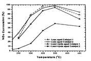
- Lean aging for Catalysts 1 and 2was carried out by exposing the catalysts to a stream of air/steam (10% steam) at an inlet temperature of 700° C. for 4 hours with a gas hourly space velocity of 30,000 h ⁇ 1 .
- Lean/rich cyclic aging for Catalysts 1 and 2was carried out with alternate lean and rich feeds at an inlet temperature of 700° C. for 4 hours with a gas hourly space velocity of 30,000 h ⁇ 1 .
- the lean feedconsisted of 500 ppm NO, 10% H 2 O and 80% N 2 .
- the rich feedconsisted of 4% CO, 0.5% C 1 (as C 3 H 6 ), 1% O 2 , 10% H 2 O and 84.5% N 2 .
- the performance testswere carried out with an alternating lean and rich feed, typically with 50 seconds lean period and 5 seconds rich period using the lean and rich feeds described above.
- the catalystswere evaluated at temperatures of 200, 250, 300, 350 and 450° C. Once the performance stabilized at a given temperature, data were collected for a period of 10 minutes.
- the NO x concentrations downstream of the catalystwere compared with those upstream of the catalyst.
- the relative disappearance of NO x concentration, expressed in percentage,was calculated throughout the data collection period at the rate of 1/second.
- the instantaneous NO x conversionswere then averaged and plotted against the catalyst inlet temperature, resulting in the graph in FIG. 1 .
- Catalyst 3was prepared in the same manner as that of Catalyst 1 with the exception that the support was gamma-alumina rather than titanium dioxide coated on alumina.
- Catalyst 4was prepared in the following manner.
- the substratewas cordierite.
- the bottom layer, deposited on the cordierite,consisted of 75 g/ft 3 platinum, 0.42 g/in 3 BaO, 0.13 g/in 3 Fe 2 O 3 , 1 g/in 3 of Al 2 O 3 support and 0.05 g/in 3 ZrO 2 .
- the alumina supportwas first impregnated with an aqueous solution of iron nitrate followed by calcination at 450° C. for 1 hour.
- the resultant powderwas then impregnated with an aqueous solution of barium acetate to achieve 0.27 g/in 3 BaO, followed by another calcination at 450° C. for 1 hour.
- the resultant powderwas then impregnated with a platinum amine salt to achieve incipient wetness.
- the powderwas then milled, in the presence of water, such that 90% of the particles had a particle size below 10 micrometers (i.e., d 90 ⁇ 10 ⁇ ), thereby resulting in a high-solids slurry.
- zirconyl acetate dissolved in waterwas added during the milling process.
- the resultant slurrywas then coated onto the cordierite and thereafter the coated cordierite was then post-dipped in a barium acetate solution to achieve additional 0.15 g/in 3 BaO.
- the resultant cordieritewas then dried at 110° C. for about one hour. Thereafter, the dried coated substrate was calcined by heating at 450° C. for one hour.
- the top layer for Catalyst 4consisted of 65 g/ft 3 platinum, 10 g/ft 3 rhodium, 0.08 g/in 3 BaO, 0.03 g/in 3 ZrO 2 and 0.20 g/in 3 of a support consisting of Al 2 O 3 .
- the process for preparing the top layer and the coating thereof on the bottom layeris identical to that described above in respect to Catalyst 1 .
- This layered catalyst compositewas identical to Catalyst 4 , except that the support for the top layer consisted of TiO 2 coated on Al 2 O 3 rather than Al 2 O 3 .
- This layered catalyst compositewas identical to Catalyst 5 , except that the support for both the bottom and top layers consisted of TiO 2 coated on Al 2 O 3 .
- the bottom layerconsisted of 65 g/ft 3 platinum, 0.35 g/in 3 BaO, 0.05 g/in 3 ZrO 2 and 1.55 g/in 3 of a support consisting of Al 2 O 3 .
- the top layer that was coated onto the bottom layerconsisted of 75 g/ft 3 platinum, 10 g/ft 3 rhodium, 0.12 g/in 3 BaO, 0.05 g/in 3 ZrO 2 and 1.5 g/in 3 of a support consisting of Al 2 O 3 .
- Catalysts 1 – 7were exposed to lean/rich cyclic thermal treatment at 700° C. as described above under Lean/Rich Cyclic Aging Conditions. The performance of each catalyst was then determined by the method described above under Catalyst Test Performance Protocols for Catalysts 1 and 2 . The result of the comparison of Catalysts 1 – 7 is set forth in the graph in FIG. 2 .
- the substrateconsisted of cordierite.
- the bottom layerconsisted of 75 g/ft 3 platinum, 0.42 g/in 3 BaO, 0.05 g/in 3 ZrO 2 and 1.83 g/in 3 of a support consisting of CeO 2 -coated Al 2 O 3 ,
- This supportwas prepared by the incipient wetness technique to allow 10 wt. % of CeO 2 on the surface of the Al 2 O 3 .
- the support materialwas impregnated with a platinum-amine salt to achieve the desired loading.
- the powderwas then milled, in the presence of water, such that 90% of the particles had a particle size below 10 micrometers (i.e., d 90 ⁇ 10 ⁇ ), thereby resulting in a high-solids slurry.
- barium acetate and zirconyl acetate dissolved in waterwere also added during the milling process.
- the slurry of the bottom layerwas then wash-coated on the cordierite substrate and the coated substrate was then dried at 110° C. for about one hour. Thereafter, the dried coated substrate was calcined by heating in a stream of flowing air at 450° C. for one hour.
- the top layer slurrywas then wash-coated on the surface of the bottom layer, dried at 110° C. for about one hour and thereafter calcined by heating at 450° C. for one hour.
- the slurry for the top layerwas prepared in the same manner as that described above for the bottom layer.
- the top layerconsisted of 75 g/ft 3 platinum, 10 g/ft 3 rhodium, 0.08 g/in 3 BaO, 0.03 g/in 3 ZrO 2 and 1.20 g/in 3 of a support consisting of CeO 2 -coated Al 2 O 3 (10 wt. % CeO 2 ).
- the platinum and rhodium componentswere sequentially impregnated on the support material.
- the powderwas then milled, in the presence of water, such that 90% of the particles had a particle size below 10 micrometers (i.e., d 90 ⁇ 10 ⁇ ), thereby resulting in a high-solids slurry.
- d 90 ⁇ 10 ⁇10 micrometers
- barium acetate and zirconyl acetate dissolved in waterwere also added during the milling process.
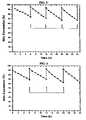
- Catalyst 8was sulfated and desulfated in the same manner as that described above in respect to the sulfation and desulfation of Catalyst 1 , except that the desulfation was carried out at 600° C. rather than 650° C.
- FIG. 4shows four consecutive sulfation and desulfation runs. As may be seen from the graph in FIG. 4 , the NO x conversion for Catalyst 8 had recovered to its original level.
Landscapes
- Engineering & Computer Science (AREA)
- Chemical & Material Sciences (AREA)
- Chemical Kinetics & Catalysis (AREA)
- Combustion & Propulsion (AREA)
- Organic Chemistry (AREA)
- Materials Engineering (AREA)
- General Engineering & Computer Science (AREA)
- Mechanical Engineering (AREA)
- Biomedical Technology (AREA)
- Oil, Petroleum & Natural Gas (AREA)
- General Chemical & Material Sciences (AREA)
- Analytical Chemistry (AREA)
- Environmental & Geological Engineering (AREA)
- Health & Medical Sciences (AREA)
- Catalysts (AREA)
- Exhaust Gas After Treatment (AREA)
Abstract
Description
- (a) a substrate;
- (b) at least one bottom layer having a bottom surface and a top surface wherein the bottom surface is adjacent to, and in contact with, the substrate, said bottom layer comprising a support upon which is deposited: (i) at least one precious metal and (ii) at least one NOxstorage component present in the amount of about 0.3 to about 1.5 g/in3; and
- (c) at least one top layer having a bottom surface and a top surface wherein the bottom surface is adjacent to, and in contact with, the top surface of the bottom layer, said top layer comprising a support upon which is deposited (i) at least one precious metal, and (ii) at least one NOxstorage component present in the amount of 0.0 to less than about 0.3 g/in3.
Claims (35)
Priority Applications (5)
| Application Number | Priority Date | Filing Date | Title |
|---|---|---|---|
| US10/355,779US7022646B2 (en) | 2003-01-31 | 2003-01-31 | Layered catalyst composite |
| KR1020057013992AKR101041270B1 (en) | 2003-01-31 | 2004-01-20 | Layered Catalyst Composites and Their Uses |
| EP04703577AEP1587605A1 (en) | 2003-01-31 | 2004-01-20 | Layered catalyst composite and use thereof |
| PCT/US2004/001271WO2004069389A1 (en) | 2003-01-31 | 2004-01-20 | Layered catalyst composite and use thereof |
| JP2006502880AJP2006518276A (en) | 2003-01-31 | 2004-01-20 | Layered catalyst composite and method of using the same |
Applications Claiming Priority (1)
| Application Number | Priority Date | Filing Date | Title |
|---|---|---|---|
| US10/355,779US7022646B2 (en) | 2003-01-31 | 2003-01-31 | Layered catalyst composite |
Publications (2)
| Publication Number | Publication Date |
|---|---|
| US20040151645A1 US20040151645A1 (en) | 2004-08-05 |
| US7022646B2true US7022646B2 (en) | 2006-04-04 |
Family
ID=32770622
Family Applications (1)
| Application Number | Title | Priority Date | Filing Date |
|---|---|---|---|
| US10/355,779Expired - LifetimeUS7022646B2 (en) | 2003-01-31 | 2003-01-31 | Layered catalyst composite |
Country Status (5)
| Country | Link |
|---|---|
| US (1) | US7022646B2 (en) |
| EP (1) | EP1587605A1 (en) |
| JP (1) | JP2006518276A (en) |
| KR (1) | KR101041270B1 (en) |
| WO (1) | WO2004069389A1 (en) |
Cited By (37)
| Publication number | Priority date | Publication date | Assignee | Title |
|---|---|---|---|---|
| US20050054524A1 (en)* | 2003-09-10 | 2005-03-10 | Engelhard Corporation | Layered ammonia oxidation catalyst |
| US20050090392A1 (en)* | 2003-10-25 | 2005-04-28 | Korea Institute Of Science And Technology | Structured catalyst for POX reforming of gasoline for fuel-cell powered vehicles applications and a method of preparing the same |
| US20060128562A1 (en)* | 2004-12-10 | 2006-06-15 | Mazda Motor Corporation | Exhaust gas purification catalyst |
| US20080044329A1 (en)* | 2006-08-21 | 2008-02-21 | Chen Shau-Lin F | Layered Catalyst Composite |
| US20080120971A1 (en)* | 2004-11-30 | 2008-05-29 | Daiji Nagaoka | Nitrogen Oxide Purification System |
| US20080182473A1 (en)* | 2007-01-16 | 2008-07-31 | Dow Global Technologies Inc. | Stretch fabrics and garments of olefin block polymers |
| WO2008097702A1 (en) | 2007-02-02 | 2008-08-14 | Basf Catalysts Llc | Multilayered three-way conversion catalyst compositions |
| US20090041643A1 (en)* | 2007-08-09 | 2009-02-12 | Michel Deeba | Multilayered Catalyst Compositions |
| US20090041644A1 (en)* | 2007-08-09 | 2009-02-12 | Knut Wassermann | Catalyst Compositions |
| US20090175773A1 (en)* | 2008-01-08 | 2009-07-09 | Chen Shau-Lin F | Multilayered Catalyst Compositions |
| US20090257933A1 (en)* | 2006-08-21 | 2009-10-15 | Basf Catalysts Llc | Layered Catalyst Composite |
| US20100056367A1 (en)* | 2007-01-26 | 2010-03-04 | Cataler Corporation | Exhaust gas purifying catalyst |
| US20100104491A1 (en)* | 2007-08-09 | 2010-04-29 | Basf Catalysts Llc | Multilayered Catalyst Compositions |
| US20100137132A1 (en)* | 2007-04-20 | 2010-06-03 | Yoshitsugu Ogura | Sulfur storage catalyst |
| US20100150792A1 (en)* | 2005-08-01 | 2010-06-17 | Cataler Corporation | Exhaust gas purifying catayst |
| US20100158780A1 (en)* | 2008-12-23 | 2010-06-24 | Basf Catalysts Llc | Small Engine Palladium Catalyst Article and Method of Making |
| US20100221154A1 (en)* | 2009-03-02 | 2010-09-02 | Gm Global Technology Operations, Inc. | Method and apparatus for reducing nox emissions from a lean burning hydrocarbon fueled power source |
| US20100263357A1 (en)* | 2006-06-29 | 2010-10-21 | Dieter Lindner | Three way catalyst |
| US20100263358A1 (en)* | 2009-04-17 | 2010-10-21 | Basf Corporation | Multi-Zoned Catalyst Compositions |
| US20100275579A1 (en)* | 2007-09-28 | 2010-11-04 | Umicore Ag & Co Kg | Removal of particulates from the exhaust gas of internal combustion engines operated with a predominantly stoichiometric air/fuel mixture |
| WO2010129490A2 (en) | 2009-05-04 | 2010-11-11 | Basf Corporation | Improved lean hc conversion of twc for lean burn gasoline engines |
| US20100290964A1 (en)* | 2009-05-18 | 2010-11-18 | Southward Barry W L | HIGH Pd CONTENT DIESEL OXIDATION CATALYSTS WITH IMPROVED HYDROTHERMAL DURABILITY |
| US20110099975A1 (en)* | 2009-11-03 | 2011-05-05 | Owen Herman Bailey | Architectural diesel oxidation catalyst for enhanced no2 generator |
| US20110107752A1 (en)* | 2009-11-06 | 2011-05-12 | Basf Corporation | Small Engine Layered Catalyst Article and Method of Making |
| US20110120093A1 (en)* | 2008-04-24 | 2011-05-26 | Stephan Eckhoff | Process and apparatus for purifying exhaust gases from an internal combustion engine |
| US8007750B2 (en) | 2007-07-19 | 2011-08-30 | Basf Corporation | Multilayered catalyst compositions |
| US8038951B2 (en) | 2007-08-09 | 2011-10-18 | Basf Corporation | Catalyst compositions |
| US20110311422A1 (en)* | 2009-01-28 | 2011-12-22 | Sued-Chemie Ag | Diesel Oxidation Catalyst With Good Low-Temperature Activity |
| US20120040824A1 (en)* | 2009-04-28 | 2012-02-16 | Minoru Itou | Exhaust gas-purifying catalyst |
| US20120128557A1 (en)* | 2010-11-22 | 2012-05-24 | Nunan John G | Three-Way Catalyst Having an Upstream Single-Layer Catalyst |
| WO2012069405A1 (en) | 2010-11-22 | 2012-05-31 | Umicore Ag & Co. Kg | Three-way catalytic system having an upstream multi - layer catalyst |
| US8318632B2 (en)* | 2008-12-19 | 2012-11-27 | Cataler Corporation | Exhaust gas purification catalyst |
| US20150266014A1 (en)* | 2014-03-21 | 2015-09-24 | Basf Corporation | Integrated LNT-TWC Catalyst |
| US9409149B2 (en) | 2009-10-08 | 2016-08-09 | W. R. Grace & Co.-Conn. | Sulfur resistant cladded titania—alumina supports |
| US20160228856A1 (en)* | 2015-02-05 | 2016-08-11 | Johnson Matthey Public Limited Company | Three-way catalyst |
| US20160228818A1 (en)* | 2015-02-06 | 2016-08-11 | Johnson Matthey Public Limited Company | Three-way catalyst and its use in exhaust systems |
| US20230234035A1 (en)* | 2022-01-21 | 2023-07-27 | GM Global Technology Operations LLC | Layered catalyst structures and methods of making the same |
Families Citing this family (23)
| Publication number | Priority date | Publication date | Assignee | Title |
|---|---|---|---|---|
| KR100527943B1 (en)* | 2003-06-04 | 2005-11-09 | 현대자동차주식회사 | Method for manufacturing double layer coated Pd only three way catalyst |
| JP5217072B2 (en)* | 2003-11-14 | 2013-06-19 | トヨタ自動車株式会社 | Exhaust gas purification catalyst and process for producing the same |
| US7795172B2 (en)* | 2004-06-22 | 2010-09-14 | Basf Corporation | Layered exhaust treatment catalyst |
| JP4687389B2 (en)* | 2005-10-26 | 2011-05-25 | マツダ株式会社 | Exhaust gas purification catalyst |
| JP4714568B2 (en)* | 2005-11-22 | 2011-06-29 | マツダ株式会社 | Exhaust gas purification catalyst and method for producing the same |
| JP2007136420A (en)* | 2005-11-22 | 2007-06-07 | Mazda Motor Corp | Exhaust gas purification catalyst and method for producing the same |
| JP4851190B2 (en)* | 2006-01-13 | 2012-01-11 | 戸田工業株式会社 | Exhaust gas purification catalyst |
| JP5305904B2 (en)* | 2006-06-14 | 2013-10-02 | 株式会社キャタラー | Exhaust gas purification catalyst |
| CN101357332B (en)* | 2007-07-31 | 2013-04-10 | 比亚迪股份有限公司 | Automobile tail gas cleaning catalyst and its preparation method |
| EP2127729A1 (en)* | 2008-05-30 | 2009-12-02 | Mazda Motor Corporation | Exhaust gas purification catalyst |
| DE102009010711A1 (en) | 2009-02-27 | 2010-09-30 | Umicore Ag & Co. Kg | Nitrogen storage catalytic converter for use in motor vehicles in close-up position |
| US9662611B2 (en) | 2009-04-03 | 2017-05-30 | Basf Corporation | Emissions treatment system with ammonia-generating and SCR catalysts |
| WO2010151461A2 (en)* | 2009-06-26 | 2010-12-29 | Uop Llc | Compounds and process for desulfurization of hot fuel gases |
| CN102470363B (en)* | 2009-07-24 | 2015-01-28 | 株式会社科特拉 | Exhaust gas purification catalyst |
| US8734743B2 (en) | 2010-06-10 | 2014-05-27 | Basf Se | NOx storage catalyst with improved hydrocarbon conversion activity |
| JP5937579B2 (en)* | 2010-06-10 | 2016-06-22 | ビーエーエスエフ ソシエタス・ヨーロピアBasf Se | NOx storage catalyst with improved hydrocarbon conversion activity |
| PL2579983T3 (en)* | 2010-06-10 | 2018-08-31 | Basf Se | Nox storage catalyst with reduced rh loading |
| US8784759B2 (en) | 2010-06-10 | 2014-07-22 | Basf Se | NOx storage catalyst with reduced Rh loading |
| CN103028429B (en)* | 2011-09-29 | 2015-08-19 | 中国科学院宁波材料技术与工程研究所 | A kind of three-way catalyst and preparation method thereof |
| CN103191736B (en)* | 2013-04-07 | 2016-01-27 | 无锡威孚环保催化剂有限公司 | The preparation method of cyclic three-way catalyst |
| CN105214723B (en)* | 2015-07-23 | 2018-05-04 | 清华大学苏州汽车研究院(吴江) | Ammoxidation catalyst of cupric and preparation method thereof |
| GB2560943A (en)* | 2017-03-29 | 2018-10-03 | Johnson Matthey Plc | NOx adsorber catalyst |
| GB2560939A (en)* | 2017-03-29 | 2018-10-03 | Johnson Matthey Plc | NOx Adsorber catalyst |
Citations (14)
| Publication number | Priority date | Publication date | Assignee | Title |
|---|---|---|---|---|
| US4868148A (en) | 1987-08-24 | 1989-09-19 | Allied-Signal Inc. | Layered automotive catalytic composite |
| US5212142A (en) | 1991-11-04 | 1993-05-18 | Engelhard Corporation | High performance thermally stable catalyst |
| WO1995035152A1 (en) | 1994-06-17 | 1995-12-28 | Engelhard Corporation | Layered catalyst composite |
| EP0705134A1 (en) | 1993-06-25 | 1996-04-10 | Engelhard Corporation | Layered catalyst composite |
| US5948723A (en) | 1996-09-04 | 1999-09-07 | Engelhard Corporation | Layered catalyst composite |
| US5981427A (en) | 1996-09-04 | 1999-11-09 | Engelhard Corporation | Catalyst composition |
| US6025297A (en) | 1996-11-14 | 2000-02-15 | Toyota Jidosha Kabushiki Kaisha | Catalyst for purifying exhaust gas and process for producing the same |
| EP0992276A1 (en) | 1998-09-29 | 2000-04-12 | Mazda Motor Corporation | Exhaust gas purifying catalyst |
| EP1066874A1 (en) | 1999-07-09 | 2001-01-10 | Nissan Motor Company, Limited | Exhaust gas purifying catalyst and method of producing same |
| EP1080783A2 (en) | 1999-09-02 | 2001-03-07 | Toyota Jidosha Kabushiki Kaisha | Layered catalyst for purifying exhaust gas |
| FR2799665A1 (en) | 1999-10-15 | 2001-04-20 | Toyota Motor Co Ltd | Catalyst, for exhaust gas purification, includes inorganic oxide layer containing noble and transition metals to protect nitrogen oxide absorber from poisoning by sulfur oxides |
| US6461579B1 (en)* | 1997-12-08 | 2002-10-08 | Toyota Jidosha Kabushiki Kaisha | Catalyst for purifying exhaust gas and exhaust gas purifying method |
| US6677264B1 (en)* | 1998-11-27 | 2004-01-13 | Degussa-Huls Aktiengesellschaft | Catalyst for cleaning up the exhaust gases of a diesel engine |
| US6764665B2 (en)* | 2001-10-26 | 2004-07-20 | Engelhard Corporation | Layered catalyst composite |
Family Cites Families (2)
| Publication number | Priority date | Publication date | Assignee | Title |
|---|---|---|---|---|
| JP3640130B2 (en)* | 1996-11-14 | 2005-04-20 | トヨタ自動車株式会社 | Exhaust gas purification catalyst and method for producing the same |
| JP4048388B2 (en)* | 1997-10-14 | 2008-02-20 | トヨタ自動車株式会社 | Exhaust gas purification catalyst |
- 2003
- 2003-01-31USUS10/355,779patent/US7022646B2/ennot_activeExpired - Lifetime
- 2004
- 2004-01-20JPJP2006502880Apatent/JP2006518276A/enactivePending
- 2004-01-20EPEP04703577Apatent/EP1587605A1/ennot_activeCeased
- 2004-01-20KRKR1020057013992Apatent/KR101041270B1/ennot_activeExpired - Lifetime
- 2004-01-20WOPCT/US2004/001271patent/WO2004069389A1/enactiveApplication Filing
Patent Citations (16)
| Publication number | Priority date | Publication date | Assignee | Title |
|---|---|---|---|---|
| US4868148A (en) | 1987-08-24 | 1989-09-19 | Allied-Signal Inc. | Layered automotive catalytic composite |
| US5212142A (en) | 1991-11-04 | 1993-05-18 | Engelhard Corporation | High performance thermally stable catalyst |
| EP0705134A1 (en) | 1993-06-25 | 1996-04-10 | Engelhard Corporation | Layered catalyst composite |
| US5597771A (en) | 1993-06-25 | 1997-01-28 | Engelhard Corporation | Layered catalyst composite |
| WO1995035152A1 (en) | 1994-06-17 | 1995-12-28 | Engelhard Corporation | Layered catalyst composite |
| US5948723A (en) | 1996-09-04 | 1999-09-07 | Engelhard Corporation | Layered catalyst composite |
| US5981427A (en) | 1996-09-04 | 1999-11-09 | Engelhard Corporation | Catalyst composition |
| US5989507A (en) | 1996-09-04 | 1999-11-23 | Engelhard Corporation | Catalyst composition |
| US6025297A (en) | 1996-11-14 | 2000-02-15 | Toyota Jidosha Kabushiki Kaisha | Catalyst for purifying exhaust gas and process for producing the same |
| US6461579B1 (en)* | 1997-12-08 | 2002-10-08 | Toyota Jidosha Kabushiki Kaisha | Catalyst for purifying exhaust gas and exhaust gas purifying method |
| EP0992276A1 (en) | 1998-09-29 | 2000-04-12 | Mazda Motor Corporation | Exhaust gas purifying catalyst |
| US6677264B1 (en)* | 1998-11-27 | 2004-01-13 | Degussa-Huls Aktiengesellschaft | Catalyst for cleaning up the exhaust gases of a diesel engine |
| EP1066874A1 (en) | 1999-07-09 | 2001-01-10 | Nissan Motor Company, Limited | Exhaust gas purifying catalyst and method of producing same |
| EP1080783A2 (en) | 1999-09-02 | 2001-03-07 | Toyota Jidosha Kabushiki Kaisha | Layered catalyst for purifying exhaust gas |
| FR2799665A1 (en) | 1999-10-15 | 2001-04-20 | Toyota Motor Co Ltd | Catalyst, for exhaust gas purification, includes inorganic oxide layer containing noble and transition metals to protect nitrogen oxide absorber from poisoning by sulfur oxides |
| US6764665B2 (en)* | 2001-10-26 | 2004-07-20 | Engelhard Corporation | Layered catalyst composite |
Cited By (76)
| Publication number | Priority date | Publication date | Assignee | Title |
|---|---|---|---|---|
| US7410626B2 (en)* | 2003-09-10 | 2008-08-12 | Basf Catalysts Llc | Layered ammonia oxidation catalyst |
| US20050054524A1 (en)* | 2003-09-10 | 2005-03-10 | Engelhard Corporation | Layered ammonia oxidation catalyst |
| US7256154B2 (en)* | 2003-10-25 | 2007-08-14 | Korea Institute Of Science And Technology | Structured catalyst for POX reforming of gasoline for fuel-cell powered vehicles applications and a method of preparing the same |
| US20050090392A1 (en)* | 2003-10-25 | 2005-04-28 | Korea Institute Of Science And Technology | Structured catalyst for POX reforming of gasoline for fuel-cell powered vehicles applications and a method of preparing the same |
| US7547659B2 (en) | 2003-10-25 | 2009-06-16 | Korea Institute Of Science And Technology | Structured catalyst for POX reforming of gasoline for fuel-cell powered vehicles applications and a method of preparing the same |
| US7560047B2 (en) | 2003-10-25 | 2009-07-14 | Korea Institute Of Science And Technology | Structured catalyst for POX reforming of gasoline for fuel-cell powered vehicles applications and a method of preparing the same |
| US20070041896A1 (en)* | 2003-10-25 | 2007-02-22 | Korea Institute Of Science And Technology | Structured catalyst for POX reforming of gasoline for fuel-cell powered vehicles applications and a method of preparing the same |
| US20080296535A1 (en)* | 2003-10-25 | 2008-12-04 | Korea Institute Of Science And Technology | Structured catalyst for POX reforming of gasoline for fuel-cell powered vehicles applications and a method of preparing the same |
| US20080120971A1 (en)* | 2004-11-30 | 2008-05-29 | Daiji Nagaoka | Nitrogen Oxide Purification System |
| US8058205B2 (en)* | 2004-11-30 | 2011-11-15 | Isuzu Motors Limited | Nitrogen oxide purification system |
| US20060128562A1 (en)* | 2004-12-10 | 2006-06-15 | Mazda Motor Corporation | Exhaust gas purification catalyst |
| US7446076B2 (en)* | 2004-12-10 | 2008-11-04 | Mazda Motor Corporation | Exhaust gas purification catalyst |
| US7998896B2 (en)* | 2005-08-01 | 2011-08-16 | Cataler Corporation | Exhaust gas purifying catalyst |
| US20100150792A1 (en)* | 2005-08-01 | 2010-06-17 | Cataler Corporation | Exhaust gas purifying catayst |
| US20100263357A1 (en)* | 2006-06-29 | 2010-10-21 | Dieter Lindner | Three way catalyst |
| US8663588B2 (en)* | 2006-06-29 | 2014-03-04 | Umicore Ag & Co. Kg | Three way catalyst |
| US7758834B2 (en) | 2006-08-21 | 2010-07-20 | Basf Corporation | Layered catalyst composite |
| US7550124B2 (en) | 2006-08-21 | 2009-06-23 | Basf Catalysts Llc | Layered catalyst composite |
| US20080044329A1 (en)* | 2006-08-21 | 2008-02-21 | Chen Shau-Lin F | Layered Catalyst Composite |
| US20090257933A1 (en)* | 2006-08-21 | 2009-10-15 | Basf Catalysts Llc | Layered Catalyst Composite |
| US20080182473A1 (en)* | 2007-01-16 | 2008-07-31 | Dow Global Technologies Inc. | Stretch fabrics and garments of olefin block polymers |
| US20100056367A1 (en)* | 2007-01-26 | 2010-03-04 | Cataler Corporation | Exhaust gas purifying catalyst |
| US8496899B2 (en)* | 2007-01-26 | 2013-07-30 | Cataler Corporation | Exhaust gas purifying catalyst |
| WO2008097702A1 (en) | 2007-02-02 | 2008-08-14 | Basf Catalysts Llc | Multilayered three-way conversion catalyst compositions |
| US20080219906A1 (en)* | 2007-02-02 | 2008-09-11 | Chen Shau-Lin F | Multilayered Catalyst Compositions |
| US7754171B2 (en) | 2007-02-02 | 2010-07-13 | Basf Corporation | Multilayered catalyst compositions |
| US8084389B2 (en)* | 2007-04-20 | 2011-12-27 | Toyota Jidosha Kabushiki Kaisha | Sulfur storage catalyst |
| US20100137132A1 (en)* | 2007-04-20 | 2010-06-03 | Yoshitsugu Ogura | Sulfur storage catalyst |
| US8007750B2 (en) | 2007-07-19 | 2011-08-30 | Basf Corporation | Multilayered catalyst compositions |
| EP2532422A2 (en) | 2007-08-09 | 2012-12-12 | BASF Catalysts LLC | Catalyst compositions |
| US20090041643A1 (en)* | 2007-08-09 | 2009-02-12 | Michel Deeba | Multilayered Catalyst Compositions |
| US7622096B2 (en) | 2007-08-09 | 2009-11-24 | Basf Catalysts Llc | Multilayered catalyst compositions |
| US20090041644A1 (en)* | 2007-08-09 | 2009-02-12 | Knut Wassermann | Catalyst Compositions |
| US8038951B2 (en) | 2007-08-09 | 2011-10-18 | Basf Corporation | Catalyst compositions |
| US7879755B2 (en) | 2007-08-09 | 2011-02-01 | Basf Corporation | Catalyst compositions |
| US7922988B2 (en) | 2007-08-09 | 2011-04-12 | Michel Deeba | Multilayered catalyst compositions |
| US20100104491A1 (en)* | 2007-08-09 | 2010-04-29 | Basf Catalysts Llc | Multilayered Catalyst Compositions |
| US8640440B2 (en)* | 2007-09-28 | 2014-02-04 | Umicore Ag & Co. Kg | Removal of particulates from the exhaust gas of internal combustion engines operated with a predominantly stoichiometric air/fuel mixture |
| US20100275579A1 (en)* | 2007-09-28 | 2010-11-04 | Umicore Ag & Co Kg | Removal of particulates from the exhaust gas of internal combustion engines operated with a predominantly stoichiometric air/fuel mixture |
| US20090175773A1 (en)* | 2008-01-08 | 2009-07-09 | Chen Shau-Lin F | Multilayered Catalyst Compositions |
| US20110120093A1 (en)* | 2008-04-24 | 2011-05-26 | Stephan Eckhoff | Process and apparatus for purifying exhaust gases from an internal combustion engine |
| US8318632B2 (en)* | 2008-12-19 | 2012-11-27 | Cataler Corporation | Exhaust gas purification catalyst |
| US7981390B2 (en) | 2008-12-23 | 2011-07-19 | Basf Corporation | Small engine palladium catalyst article and method of making |
| US20100158780A1 (en)* | 2008-12-23 | 2010-06-24 | Basf Catalysts Llc | Small Engine Palladium Catalyst Article and Method of Making |
| US20110311422A1 (en)* | 2009-01-28 | 2011-12-22 | Sued-Chemie Ag | Diesel Oxidation Catalyst With Good Low-Temperature Activity |
| US8859454B2 (en)* | 2009-01-28 | 2014-10-14 | Clariant Produkte (Deutschland) Gmbh | Diesel oxidation catalyst with good low-temperature activity |
| US20100221154A1 (en)* | 2009-03-02 | 2010-09-02 | Gm Global Technology Operations, Inc. | Method and apparatus for reducing nox emissions from a lean burning hydrocarbon fueled power source |
| US8920759B2 (en)* | 2009-03-02 | 2014-12-30 | GM Global Technology Operations LLC | Method and apparatus for reducing NOx emissions from a lean burning hydrocarbon fueled power source |
| US20100263358A1 (en)* | 2009-04-17 | 2010-10-21 | Basf Corporation | Multi-Zoned Catalyst Compositions |
| US8940242B2 (en) | 2009-04-17 | 2015-01-27 | Basf Corporation | Multi-zoned catalyst compositions |
| US20120040824A1 (en)* | 2009-04-28 | 2012-02-16 | Minoru Itou | Exhaust gas-purifying catalyst |
| US8927454B2 (en)* | 2009-04-28 | 2015-01-06 | Cataler Corporation | Exhaust gas-purifying catalyst |
| US20130189173A1 (en)* | 2009-05-04 | 2013-07-25 | Marcus Hilgendorff | Lean hc conversion of twc for lean burn gasoline engines |
| WO2010129490A2 (en) | 2009-05-04 | 2010-11-11 | Basf Corporation | Improved lean hc conversion of twc for lean burn gasoline engines |
| US8906330B2 (en)* | 2009-05-04 | 2014-12-09 | Basf Corporation | Lean HC conversion of TWC for lean burn gasoline engines |
| US8246923B2 (en)* | 2009-05-18 | 2012-08-21 | Umicore Ag & Co. Kg | High Pd content diesel oxidation catalysts with improved hydrothermal durability |
| US20100290964A1 (en)* | 2009-05-18 | 2010-11-18 | Southward Barry W L | HIGH Pd CONTENT DIESEL OXIDATION CATALYSTS WITH IMPROVED HYDROTHERMAL DURABILITY |
| US9409149B2 (en) | 2009-10-08 | 2016-08-09 | W. R. Grace & Co.-Conn. | Sulfur resistant cladded titania—alumina supports |
| US8557203B2 (en)* | 2009-11-03 | 2013-10-15 | Umicore Ag & Co. Kg | Architectural diesel oxidation catalyst for enhanced NO2 generator |
| US20110099975A1 (en)* | 2009-11-03 | 2011-05-05 | Owen Herman Bailey | Architectural diesel oxidation catalyst for enhanced no2 generator |
| US20110107752A1 (en)* | 2009-11-06 | 2011-05-12 | Basf Corporation | Small Engine Layered Catalyst Article and Method of Making |
| US8833064B2 (en) | 2009-11-06 | 2014-09-16 | Basf Corporation | Small engine layered catalyst article and method of making |
| US8557204B2 (en)* | 2010-11-22 | 2013-10-15 | Umicore Ag & Co. Kg | Three-way catalyst having an upstream single-layer catalyst |
| US20120128557A1 (en)* | 2010-11-22 | 2012-05-24 | Nunan John G | Three-Way Catalyst Having an Upstream Single-Layer Catalyst |
| WO2012069404A1 (en) | 2010-11-22 | 2012-05-31 | Umicore Ag & Co. Kg | Three-way catalytic system having an upstream single -layer catalyst |
| US8968690B2 (en) | 2010-11-22 | 2015-03-03 | Umicore Ag & Co. Kg | Three-way catalyst having an upstream single-layer catalyst |
| WO2012069405A1 (en) | 2010-11-22 | 2012-05-31 | Umicore Ag & Co. Kg | Three-way catalytic system having an upstream multi - layer catalyst |
| US9744529B2 (en)* | 2014-03-21 | 2017-08-29 | Basf Corporation | Integrated LNT-TWC catalyst |
| US20150266014A1 (en)* | 2014-03-21 | 2015-09-24 | Basf Corporation | Integrated LNT-TWC Catalyst |
| US9981258B2 (en) | 2014-03-21 | 2018-05-29 | Basf Corporation | Integrated LNT-TWC catalyst |
| US20160228856A1 (en)* | 2015-02-05 | 2016-08-11 | Johnson Matthey Public Limited Company | Three-way catalyst |
| US9707545B2 (en)* | 2015-02-05 | 2017-07-18 | Johnson Matthey Public Limited Company | Three-way catalyst |
| US20160228818A1 (en)* | 2015-02-06 | 2016-08-11 | Johnson Matthey Public Limited Company | Three-way catalyst and its use in exhaust systems |
| US9656209B2 (en)* | 2015-02-06 | 2017-05-23 | Johnson Matthey Public Limited Company | Three-way catalyst and its use in exhaust systems |
| US20230234035A1 (en)* | 2022-01-21 | 2023-07-27 | GM Global Technology Operations LLC | Layered catalyst structures and methods of making the same |
| US11772078B2 (en)* | 2022-01-21 | 2023-10-03 | GM Global Technology Operations LLC | Layered catalyst structures and methods of making the same |
Also Published As
| Publication number | Publication date |
|---|---|
| KR101041270B1 (en) | 2011-06-14 |
| WO2004069389A1 (en) | 2004-08-19 |
| JP2006518276A (en) | 2006-08-10 |
| EP1587605A1 (en) | 2005-10-26 |
| KR20050091789A (en) | 2005-09-15 |
| US20040151645A1 (en) | 2004-08-05 |
Similar Documents
| Publication | Publication Date | Title |
|---|---|---|
| US7022646B2 (en) | Layered catalyst composite | |
| US8950174B2 (en) | Catalysts for gasoline lean burn engines with improved NH3-formation activity | |
| KR100431476B1 (en) | Layered Catalyst Composite | |
| EP2427637B1 (en) | Improved lean hc conversion of twc for lean burn gasoline engines | |
| EP2611535B1 (en) | Catalyst for gasoline lean burn engines with improved no oxidation activity | |
| US7037875B2 (en) | Catalyst support | |
| JP4359508B2 (en) | Layered catalyst composite | |
| EP2611536B1 (en) | Catalyst for gasoline lean burn engines with improved nh3-formation activity | |
| EP2969191B1 (en) | Catalyst materials for no oxidation | |
| JP2002535135A (en) | Catalyst composition containing oxygen storage component | |
| US6555081B2 (en) | Method of the purification of the exhaust gas from a lean-burn engine using a catalyst | |
| WO2010103870A1 (en) | Exhaust gas purifying catalyst, exhaust gas purifying apparatus using same, and method for purifying exhaust gas | |
| US10449522B2 (en) | Process for manufacture of NOx storage materials | |
| JPH06285371A (en) | Catalyst for purifying exhaust gas from lean burn engine and purifying method | |
| JP2004523336A (en) | Catalyst materials and methods for reducing nitrogen oxides |
Legal Events
| Date | Code | Title | Description |
|---|---|---|---|
| AS | Assignment | Owner name:ENGELHARD CORPORATION, NEW JERSEY Free format text:ASSIGNMENT OF ASSIGNORS INTEREST;ASSIGNOR:LI, YUEJIN;REEL/FRAME:013826/0920 Effective date:20030131 | |
| STCF | Information on status: patent grant | Free format text:PATENTED CASE | |
| FPAY | Fee payment | Year of fee payment:4 | |
| FPAY | Fee payment | Year of fee payment:8 | |
| MAFP | Maintenance fee payment | Free format text:PAYMENT OF MAINTENANCE FEE, 12TH YEAR, LARGE ENTITY (ORIGINAL EVENT CODE: M1553) Year of fee payment:12 | |
| AS | Assignment | Owner name:BASF MOBILE EMISSIONS CATALYSTS LLC, NEW JERSEY Free format text:NUNC PRO TUNC ASSIGNMENT;ASSIGNOR:BASF CORPORATION;REEL/FRAME:070674/0653 Effective date:20241217 Owner name:BASF CORPORATION, NEW JERSEY Free format text:MERGER;ASSIGNOR:BASF CATALYSTS LLC;REEL/FRAME:070674/0513 Effective date:20100401 Owner name:BASF CATALYSTS LLC, NEW JERSEY Free format text:CHANGE OF NAME;ASSIGNOR:ENGELHARD CORPORATION;REEL/FRAME:070674/0491 Effective date:20060801 |