US7022225B1 - Water ozonation mixing and degassing system - Google Patents
Water ozonation mixing and degassing systemDownload PDFInfo
- Publication number
- US7022225B1 US7022225B1US10/701,163US70116303AUS7022225B1US 7022225 B1US7022225 B1US 7022225B1US 70116303 AUS70116303 AUS 70116303AUS 7022225 B1US7022225 B1US 7022225B1
- Authority
- US
- United States
- Prior art keywords
- ozone
- structured
- separating vessel
- water
- gas
- Prior art date
- Legal status (The legal status is an assumption and is not a legal conclusion. Google has not performed a legal analysis and makes no representation as to the accuracy of the status listed.)
- Expired - Lifetime
Links
- XLYOFNOQVPJJNP-UHFFFAOYSA-NwaterSubstancesOXLYOFNOQVPJJNP-UHFFFAOYSA-N0.000titleclaimsabstractdescription174
- 238000002156mixingMethods0.000titleclaimsabstractdescription86
- 238000007872degassingMethods0.000titledescription6
- 238000006385ozonation reactionMethods0.000titledescription4
- CBENFWSGALASAD-UHFFFAOYSA-NOzoneChemical compound[O-][O+]=OCBENFWSGALASAD-UHFFFAOYSA-N0.000claimsabstractdescription242
- 230000007246mechanismEffects0.000claimsabstractdescription26
- 239000007788liquidSubstances0.000claimsabstractdescription17
- 239000000203mixtureSubstances0.000claimsdescription48
- 239000000463materialSubstances0.000claimsdescription21
- 239000003054catalystSubstances0.000claimsdescription15
- OKTJSMMVPCPJKN-UHFFFAOYSA-NCarbonChemical compound[C]OKTJSMMVPCPJKN-UHFFFAOYSA-N0.000claimsdescription8
- 230000002209hydrophobic effectEffects0.000claimsdescription8
- 230000009977dual effectEffects0.000claimsdescription7
- 230000008901benefitEffects0.000claimsdescription6
- NUJOXMJBOLGQSY-UHFFFAOYSA-Nmanganese dioxideChemical compoundO=[Mn]=ONUJOXMJBOLGQSY-UHFFFAOYSA-N0.000claimsdescription4
- 238000007599dischargingMethods0.000claims2
- 238000011012sanitizationMethods0.000abstractdescription15
- 230000001351cycling effectEffects0.000abstractdescription6
- 230000001965increasing effectEffects0.000abstractdescription5
- 230000002708enhancing effectEffects0.000abstractdescription3
- 239000007789gasSubstances0.000description101
- 239000013505freshwaterSubstances0.000description8
- 238000000926separation methodMethods0.000description7
- 230000009182swimmingEffects0.000description5
- 238000013022ventingMethods0.000description5
- 239000003795chemical substances by applicationSubstances0.000description3
- 230000001276controlling effectEffects0.000description3
- 230000000694effectsEffects0.000description3
- 238000002169hydrotherapyMethods0.000description3
- 238000002347injectionMethods0.000description3
- 239000007924injectionSubstances0.000description3
- 238000000034methodMethods0.000description3
- 238000012546transferMethods0.000description3
- IJGRMHOSHXDMSA-UHFFFAOYSA-NAtomic nitrogenChemical compoundN#NIJGRMHOSHXDMSA-UHFFFAOYSA-N0.000description2
- QVGXLLKOCUKJST-UHFFFAOYSA-Natomic oxygenChemical compound[O]QVGXLLKOCUKJST-UHFFFAOYSA-N0.000description2
- 230000004888barrier functionEffects0.000description2
- 238000006243chemical reactionMethods0.000description2
- 238000004891communicationMethods0.000description2
- 238000009833condensationMethods0.000description2
- 230000005494condensationEffects0.000description2
- 238000010276constructionMethods0.000description2
- 238000010438heat treatmentMethods0.000description2
- 238000012423maintenanceMethods0.000description2
- 239000012528membraneSubstances0.000description2
- 230000004048modificationEffects0.000description2
- 238000012986modificationMethods0.000description2
- 239000001301oxygenSubstances0.000description2
- 229910052760oxygenInorganic materials0.000description2
- 238000000746purificationMethods0.000description2
- 230000004044responseEffects0.000description2
- 239000003643water by typeSubstances0.000description2
- 241000894006BacteriaSpecies0.000description1
- 241000195493CryptophytaSpecies0.000description1
- 230000002411adverseEffects0.000description1
- 238000009360aquacultureMethods0.000description1
- 244000144974aquacultureSpecies0.000description1
- 230000003197catalytic effectEffects0.000description1
- 238000013461designMethods0.000description1
- 238000004090dissolutionMethods0.000description1
- 238000001914filtrationMethods0.000description1
- 239000012530fluidSubstances0.000description1
- -1for exampleSubstances0.000description1
- 231100000206health hazardToxicity0.000description1
- 229910052757nitrogenInorganic materials0.000description1
- 238000010943off-gassingMethods0.000description1
- 239000007800oxidant agentSubstances0.000description1
- 230000003647oxidationEffects0.000description1
- 238000007254oxidation reactionMethods0.000description1
- 230000001590oxidative effectEffects0.000description1
- 238000009428plumbingMethods0.000description1
- 239000012629purifying agentSubstances0.000description1
- 230000001105regulatory effectEffects0.000description1
- 150000003839saltsChemical class0.000description1
- 238000004513sizingMethods0.000description1
- 229910001220stainless steelInorganic materials0.000description1
- 239000010935stainless steelSubstances0.000description1
- 239000000126substanceSubstances0.000description1
- 238000013024troubleshootingMethods0.000description1
- 238000011144upstream manufacturingMethods0.000description1
- 230000003245working effectEffects0.000description1
Images


Classifications
- C—CHEMISTRY; METALLURGY
- C02—TREATMENT OF WATER, WASTE WATER, SEWAGE, OR SLUDGE
- C02F—TREATMENT OF WATER, WASTE WATER, SEWAGE, OR SLUDGE
- C02F1/00—Treatment of water, waste water, or sewage
- C02F1/72—Treatment of water, waste water, or sewage by oxidation
- C02F1/78—Treatment of water, waste water, or sewage by oxidation with ozone
- B—PERFORMING OPERATIONS; TRANSPORTING
- B01—PHYSICAL OR CHEMICAL PROCESSES OR APPARATUS IN GENERAL
- B01D—SEPARATION
- B01D19/00—Degasification of liquids
- B01D19/0063—Regulation, control including valves and floats
- B—PERFORMING OPERATIONS; TRANSPORTING
- B01—PHYSICAL OR CHEMICAL PROCESSES OR APPARATUS IN GENERAL
- B01D—SEPARATION
- B01D53/00—Separation of gases or vapours; Recovering vapours of volatile solvents from gases; Chemical or biological purification of waste gases, e.g. engine exhaust gases, smoke, fumes, flue gases, aerosols
- B01D53/34—Chemical or biological purification of waste gases
- B01D53/74—General processes for purification of waste gases; Apparatus or devices specially adapted therefor
- B01D53/86—Catalytic processes
- B01D53/8671—Removing components of defined structure not provided for in B01D53/8603 - B01D53/8668
- B01D53/8675—Ozone
- B—PERFORMING OPERATIONS; TRANSPORTING
- B01—PHYSICAL OR CHEMICAL PROCESSES OR APPARATUS IN GENERAL
- B01D—SEPARATION
- B01D2255/00—Catalysts
- B01D2255/20—Metals or compounds thereof
- B01D2255/207—Transition metals
- B01D2255/2073—Manganese
- B—PERFORMING OPERATIONS; TRANSPORTING
- B01—PHYSICAL OR CHEMICAL PROCESSES OR APPARATUS IN GENERAL
- B01D—SEPARATION
- B01D2255/00—Catalysts
- B01D2255/70—Non-metallic catalysts, additives or dopants
- B01D2255/702—Carbon
- C—CHEMISTRY; METALLURGY
- C02—TREATMENT OF WATER, WASTE WATER, SEWAGE, OR SLUDGE
- C02F—TREATMENT OF WATER, WASTE WATER, SEWAGE, OR SLUDGE
- C02F1/00—Treatment of water, waste water, or sewage
- C02F1/20—Treatment of water, waste water, or sewage by degassing, i.e. liberation of dissolved gases
- C—CHEMISTRY; METALLURGY
- C02—TREATMENT OF WATER, WASTE WATER, SEWAGE, OR SLUDGE
- C02F—TREATMENT OF WATER, WASTE WATER, SEWAGE, OR SLUDGE
- C02F2103/00—Nature of the water, waste water, sewage or sludge to be treated
- C02F2103/42—Nature of the water, waste water, sewage or sludge to be treated from bathing facilities, e.g. swimming pools
- C—CHEMISTRY; METALLURGY
- C02—TREATMENT OF WATER, WASTE WATER, SEWAGE, OR SLUDGE
- C02F—TREATMENT OF WATER, WASTE WATER, SEWAGE, OR SLUDGE
- C02F2201/00—Apparatus for treatment of water, waste water or sewage
- C02F2201/78—Details relating to ozone treatment devices
- C02F2201/784—Diffusers or nozzles for ozonation
- Y—GENERAL TAGGING OF NEW TECHNOLOGICAL DEVELOPMENTS; GENERAL TAGGING OF CROSS-SECTIONAL TECHNOLOGIES SPANNING OVER SEVERAL SECTIONS OF THE IPC; TECHNICAL SUBJECTS COVERED BY FORMER USPC CROSS-REFERENCE ART COLLECTIONS [XRACs] AND DIGESTS
- Y10—TECHNICAL SUBJECTS COVERED BY FORMER USPC
- Y10S—TECHNICAL SUBJECTS COVERED BY FORMER USPC CROSS-REFERENCE ART COLLECTIONS [XRACs] AND DIGESTS
- Y10S261/00—Gas and liquid contact apparatus
- Y10S261/42—Ozonizers
Definitions
- the present inventiongenerally relates to a mixing and degassing system for ozonating water and more specifically relates to an ozone/water mixing and degassing system for purifying water for residential and commercial spa/pool use.
- ozonecan be an effective oxidizing and sanitizing agent for treating water in a spa or pool.
- Ozone gasis sometimes mixed with water to form a sanitizing treatment stream that is introduced into the body of water being sanitized.
- conventional ozone water mixing systemsare not ideal for use in forming an ozonated water treatment stream that is suitable for use with conventional pools or spas, particularly with respect to small scale applications, for example, residential pools and spas.
- ozonation of water for purposes of oxidation and sanitationrequires efficient transfer of ozone gas, in the dissolved state, into water in the ozonated water treatment stream.
- Inefficient dissolution, or mass transfer, of ozone into the waterresults in wasted, undissolved ozone gas being released from the surface of the water.
- large scale commercial spa and pool systems using ozone for purificationconventionally utilize separate, individual components to provide the necessary functions of (1) injection of ozone gas into water, (2) mixing of the ozonated water, and (3) separation and venting of undissolved gas, including ozone gas, from the ozonated water stream.
- These separate componentsare relatively bulky, complicated to interconnect, and take up significant amounts of space, which limits their practical and cost effective use to large scale commercial applications, not to consumer or residential applications.
- combination ozone injectors and mixing chambersare commercially available, they are typically too large, expensive and/or technically complicated for use on residential size pools and spas. For example, one such combination system commercially available relies upon large, serpentine pipes to provide the mixing function.
- Destruct unitsare constructed in various ways that will be known to those of skill in the art and involved in the industry.
- One common method of destroying ozone off-gas in low to medium range concentrationsis by passing the off-gas through a catalyst bed.
- catalyst bedsare most effective when ozone is allowed to come in direct contact with the catalyst material itself, and only if the material remains sufficiently dry.
- Commercial heatersare therefore sometimes employed to prevent condensation and moisture intrusion into the catalyst bed.
- the present inventionaddresses these issues in a cost effective manner designed specifically for use with ozone water treatment systems but with other applications as well.
- the present inventionprovides safe and effective apparatus and systems which overcome one or more of the above-noted and other problems.
- the present apparatus and systemsare straightforward in construction and use, are highly convenient to install and use, and are effective in purifying water for spa and pool use.
- an ozone/water mixing apparatuswhich generally comprises a separating vessel structured to contain and degas an ozone/aqueous mixture, the separating vessel including an off-gas outlet placed and structured to vent undissolved ozone gas from the separating vessel, and an ozonated water outlet placed and structured to pass the ozone/aqueous mixture from the separating vessel to an application for use.
- the apparatusmay further comprise a mixing tower, preferably extending into the separating vessel, the mixing tower including an inlet portion structured to receive an ozone/aqueous mixture and an outlet portion structured to pass the ozone/aqueous mixture into the separating vessel.
- a mixing towerpreferably extending into the separating vessel, the mixing tower including an inlet portion structured to receive an ozone/aqueous mixture and an outlet portion structured to pass the ozone/aqueous mixture into the separating vessel.
- the mixing tower inlet portionpreferably includes a first inlet structured to receive an aqueous stream, for example, a water stream, and a second inlet structured to receive a gaseous stream containing ozone.
- the apparatusfurther comprises an ozone injector for example, a venturi injector, preferably located directly adjacent to, or at least partially within, the mixing tower and connected to both the first inlet and the second inlet.
- the first inletmay comprise a pipe fitting structured to be connected to a fresh water source
- the second inletmay comprise a standard tube fitting structured to be connected to a source of ozone gas, for example an ozone generator.
- the ozone injectoris positioned and structured to be effective in introducing ozone gas from the second inlet into the water stream through the first inlet to form an ozonated water mixture within the mixing tower.
- the ozone injectoris located substantially entirely within the mixing tower, and the mixing tower is located at least partially within the separating vessel, and more preferably is located substantially entirely within the separating vessel.
- the mixing towerpreferably extends a sufficient distance into the separating vessel such that an outlet portion of the mixing tower is positioned within a generally central portion of the separating vessel.
- Another especially advantageous feature of the inventionis that many of the components of the present apparatus, for example, but not limited to, the separating vessel and the mixing tower, may be comprised of an optically clear material, in order to allow viewing of the internal components of the apparatus, thereby facilitating maintenance and troubleshooting.
- the apparatusis designed to reduce the occurrence of surface turbulence within the separating vessel.
- the apparatusmay further comprise a diffuser element connected to the outlet portion of the mixing tower.
- the diffuser elementmay be structured to be effective in directing the ozonated water mixture passed from the mixing tower in a direction generally away from an upper portion of the separating vessel.
- the diffuser elementmay include spaced apart apertures, for example slots, shaped and/or positioned to direct the ozonated water mixture in a generally non-vertical direction, for example in a substantially horizontal direction, thereby diverting flow of water and bubbles away from a water/air surface within the separating vessel.
- the diffuser elementis structured to be effective in both quieting the ozonated water surface within the separating vessel, and reducing escape of dissolved ozone gas from the ozonated water mixture.
- the diffuser elementis further structured to be effective in enhancing the mixing of ozone bubbles with the water, thereby reducing a concentration of undissolved ozone gas in the separating vessel.
- the diffuser elementmay include apertures shaped and positioned to effect a rotating flow of the ozonated water within the separating vessel as the ozonated water is passed from the mixing tower.
- the apparatus of the present inventionfurther comprises an off-gas outlet, or degas valve, for venting undissolved gases, for example, undissolved ozone gases, from the separating vessel.
- an off-gas outletor degas valve, for venting undissolved gases, for example, undissolved ozone gases, from the separating vessel.
- the structure of the present inventionprovides enhanced liquid/gas separation at the off-gas outlet.
- the apparatusmay further comprise a seal mechanism designed to inhibit escape of liquid water through the off-gas outlet.
- the seal mechanismmay include a float arrangement or other means of controlling a level of ozonated water in the separating vessel in order to maintain a sufficient air space between the liquid in the separating vessel and the off-gas outlet.
- a lever mechanismfor example, a dual lever mechanism, may be provided for controlling the float arrangement and provide substantial mechanical advantage to the seal in order to create a relatively large force and a tight seal thereby substantially preventing escape of water through the off-gas outlet.
- the seal mechanismincludes a valve seat having a seal, for example, an o-ring type seal, that is angled to provide a variable cross-sectional area as the degas valve is opened.
- the apparatusfurther comprises an ozone destruct assembly for destroying undissolved ozone gas in an off-gas stream vented from the separating vessel, for example, through the off-gas outlet.
- the ozone destruct apparatusgenerally comprises an ozone destruct chamber for destroying ozone gas in the off-gas stream passing therethrough.
- the ozone destruct assemblyis designed to substantially prevent liquid water from entering the destruct chamber.
- the ozone destruct assemblymay include a condensate collection chamber adjacent the ozone destruct chamber, and structured to collect condensate within the off-gas stream being passed into the ozone destruct assembly.
- the condensate collection chambermay include an inlet structured to receive the off-gas stream from the separating vessel, and an outlet structured to pass the off-gas stream, with liquid water substantially removed therefrom, to the destruct chamber where ozone gas in the off-gas stream is removed from the off-gas stream.
- the ozone destruct apparatusmay comprise a hydrophobic material, for example a hydrophobic membrane, disposed between the destruct chamber and the condensate collection chamber for substantially preventing liquid water from entering the destruct chamber.
- a hydrophobic materialfor example a hydrophobic membrane
- the condensate collection chambermay include a drain element for allowing any collected condensate to drain from the condensate collection chamber.
- the drain elementmay include a check valve, or other mechanism, operable to release the collected condensate when a predetermined condition in the collection chamber is reached.
- the check valvemay comprise a spring loaded valve that is normally closed to flow, but is structured to open and release collected condensate in response to an increase in pressure in the collection chamber.
- the released condensateis directed for reuse, for example the condensate may be returned to ozone/water mixing apparatus.
- a gas stream vented from the ozone destruct assemblymay be vented to the atmosphere.
- the treated gas streammay be introduced into the body of water contained in the pool or spa or other main vessel, for example, by means of a reintroduction line connected to the body of water through an inlet in a wall of the main vessel.
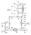
- FIG. 1shows a diagrammatical representation of an ozone/water mixing apparatus in accordance with one embodiment of the present invention, the apparatus being installed as a useful component of a plumbing system for cycling water to a spa or swimming pool.
- FIG. 2shows a partial cross-sectional view of an ozone/water mixing apparatus in accordance with an embodiment of the invention, including a separating vessel, a mixing tower and a float and dual lever seal mechanism.
- FIG. 2Ashows an enlarged view of the dual lever seal mechanism shown in FIG. 2 .
- FIG. 3 ashows a cross-sectional view of the apparatus of FIG. 2 taken along line 3 a — 3 a of FIG. 2 .
- FIG. 3 bshows a cross-sectional view of an ozone/water mixing apparatus in accordance with another embodiment of the invention, including an additional feature of ozone injector located substantially entirely within the mixing tower.
- FIG. 4shows a cross-sectional view of an ozone/water mixing apparatus in accordance with yet another embodiment of the present invention, wherein the apparatus is adapted and structured to be installed to a contact tank.
- FIG. 5shows a schematic representation of a water ozonation system in accordance with another embodiment of the present invention, the system including a preferred ozone destruct apparatus.
- FIG. 6shows an enlarged view, in cross-section, of a portion of the ozone destruct apparatus shown in FIG. 5 taken along line 6 of FIG. 5 .
- FIG. 7shows a diagrammatical representation of an ozone/water mixing apparatus in accordance with the present invention including a reintroduction line for introducing a stream of substantially ozone free gas from the ozone destruct apparatus and into the body of water being treated.
- FIG. 1an ozone/water mixing apparatus, in accordance with the present invention, is shown generally at 10 .
- the apparatus 10is shown as a very useful component of a system 12 for cycling an ozone/aqueous mixture (hereinafter sometimes referred to as “ozonated water”) for use as a sanitizer and oxidizer in a body of water 16 .
- ozonated wateran ozone/aqueous mixture
- FIG. 1shows the body of water 16 as being contained and circulated to a spa 16 a having a spa shell 16 b .
- the present ozone water mixing apparatus 10 and system 12are useful for many other applications as well, for example but not limited to, sanitation of other bodies of water, for example, water contained in a commercial or residential swimming pool, hydrotherapy spa, jetted tub or the like.
- the ozone/water mixing apparatus 10is preferably designed for performing such functions as mixing an ozone gas into a substantially ozone-free water to form a highly concentrated ozone/aqueous mixture, separating and removing undissolved ozone-containing gas from the ozone/aqueous mixture, venting undissolved ozone-containing gas, and passing the highly concentrated, substantially degassed ozone/aqueous mixture to a body of water.
- the apparatus 10is designed to produce a stream of concentrated ozonated water having an ozone concentration effective in sanitizing or purifying water in a spa, jetted tub or swimming pool.
- the apparatus 10is preferably structured to produce an ozone/aqueous mixture having a dissolved ozone concentration of between about 1.0 ppm to about 20 ppm. It is to be appreciated that the ozone dose introduced into the body of water 16 can be adjusted as desired based on the amount of fresh water being mixed therewith, as well as other modifications to the system that will be known to those of skill in the art.
- the apparatus 10generally comprises a separating vessel 20 structured to contain and degas an ozone/aqueous mixture, wherein the separating vessel 20 includes an off-gas outlet 22 placed and structured to vent gasses, including undissolved ozone gas, from the separating vessel 20 .
- the separating vesselfurther comprises an ozonated water outlet 24 placed and structured to pass the substantially degassed ozone/aqueous mixture from the separating vessel 20 to an application, (for example, spa 16 a ), for example, through line 26 , for use as a sanitizing agent.
- the system 12 for cycling an ozone/aqueous mixturemay include an ozone generator 12 a , an ozone gas line 12 b , a fresh water flow line 12 c , and an ozone injector 12 d.
- the system 12includes a bypass line 12 e for controlling a flow of fresh water to the application 16 a .
- the bypass line 12 emay be equipped with a ball valve 12 f and is structured and configured in a conventional manner to control pressure drop and flow of water to the separating vessel 20 .
- the ozonated water treatment streamis passed into the body of water 16 through a treatment stream inlet 12 h which receives the ozone/aqueous mixture from the separating vessel 10 by means of ozonated water line 12 i.
- the apparatus 10further comprises a mixing tower 30 (not visible in FIG. 1 ) extending into the separating vessel 20 , the mixing tower 30 including an inlet portion 34 structured to receive an aqueous stream, for example an ozone/aqueous stream, and an outlet portion 36 structured to pass the aqueous stream into a chamber 37 of the separating vessel 20 .
- a mixing tower 30(not visible in FIG. 1 ) extending into the separating vessel 20 , the mixing tower 30 including an inlet portion 34 structured to receive an aqueous stream, for example an ozone/aqueous stream, and an outlet portion 36 structured to pass the aqueous stream into a chamber 37 of the separating vessel 20 .
- the separating vessel 20includes an inlet 38 in fluid communication with mixing tower inlet 34 for receiving the aqueous stream, for example from line 12 , shown in FIG. 1 an ozonated water stream.
- inlet portion 34 of the mixing tower 30is adequately sized to allow for a desired flow rate, for example, a flow rate of about 4 gallons per minute to about 20 gallons per minute, to pass substantially unrestricted into mixing tower 30 through the separating vessel inlet 38 .
- the separating vessel 20preferably comprises a housing 40 , for example a substantially cylindrical housing, including a base portion 40 a , an upper portion 40 b and a body portion 40 c .
- a housing 40for example a substantially cylindrical housing, including a base portion 40 a , an upper portion 40 b and a body portion 40 c .
- both inlet 38 and outlet 24are molded, integral components of the housing base portion 40 a .
- the housing base portion 40 amay include an outlet.
- Each component of the housing 40is preferably molded of a substantially high impact, ozone compatible material, for example PVC, PP, PC or any other suitable material.
- the housing 40is transparent, or optically clear, in order to allow viewing of the inner workings of the apparatus 10 .
- the apparatus 10may optionally comprise an ozone destruct assembly 41 (not shown in FIG. 2 ) connected, for example, by means of gas line 52 , to the ozone gas outlet 22 .
- the ozone destruct assembly 41is effective to destroy at least some of the undissolved ozone gas vented from the off-gas outlet 22 .
- the ozone destruct assembly 41may be designed to utilize any of several methods of destroying ozone gas, as will be known to those of ordinary skill in the art, for example, but not limited to, the use of activated carbon, a heating element, and/or a catalytic element.
- the ozonated water outlet 24is positioned and structured to pass the ozonated water mixture from the separating vessel chamber 37 to an application for use, for example, for use as a purifying agent in a pool, spa, or jetted tub.
- the mixing tower 30comprises an extension portion 30 a that engages with an inlet plug 38 a of the housing base portion 40 a .
- the mixing tower 30further comprises a diffuser element 68 structured to provide enhanced mixing of ozone gas with water while not significantly increasing surface turbulence in the separating vessel chamber 37 .
- the diffuser element 68is located and structured to be effective in directing the ozonated water mixture from the mixing tower 30 into the separating vessel chamber 37 .
- the mixing tower 30is sized and structured to extend a substantial distance into the separating vessel 20 , for example into a generally central region of the separating vessel 20 , as shown.
- the diffuser element 68may comprise a cap portion 69 including multiple outlet ports 69 a , and a depending portion 69 b (not visible in FIG. 2 ). Extension portion 30 is located between the inlet 34 and the diffuser element 68 .
- the extension portion 30 ais preferably sized and structured to position the diffuser element 68 to an appropriate level for separation of gas bubbles and water.
- the diffuser 68is structured to be effective in directing the ozonated water mixture from the mixing tower 14 into the separating vessel 20 in a direction generally away from the ozonated water surface within the separating vessel 20 , and away from the float mechanism 80 . More preferably, the diffuser 68 is structured to direct the ozonated water mixture from the mixing tower 30 into the separating vessel 20 in a generally non-vertical, preferably a substantially horizontal direction.
- This structureeffectively functions to quiet the air/water surface and reduce turbulence within the separating vessel, thus maintaining a higher concentration of dissolved ozone in the ozone/water mixture in the chamber 37 .
- the float mechanism 80will be more effective in maintaining the liquid tight seal at the off-gas outlet 22 with minimal fluctuation.
- the apparatus 10preferably further includes a valve linkage comprised of a float mechanism 80 adapted to control a level of ozonated water in the chamber 37 of the separating vessel 20 .
- the off-gas outlet 22may include a valve 22 a , having a seat 82 and a seal 84 , structured to substantially prevent liquid water from escaping the separating vessel 40 through the off-gas outlet 22 with vented ozone off-gas.
- the float mechanism 80includes a float element 86 , and multiple lever mechanism 90 comprising hinged arms 92 and 94 which function to provide a substantial mechanical advantage to the seal 84 against the seat 82 .
- the float element 86is sized to smoothly and precisely control the water level in the chamber 37 and provide downward force necessary to open the off-gas outlet 22 under pressure.
- valve linkagehereinabove described allows for physical separation of the valve seat 82 from an ozonated water surface in the chamber 42 thus reducing the chance of water release through the off-gas outlet 22 .
- the linkagealso provides mechanical advantage to the seal in order to create a relatively large force and tight seal.
- the seal 84may comprise an O'ring type seal 96 , the seal 84 being disposed at an angle with respect to the seat 82 as shown, thereby providing a variable cross-sectional area as the valve opens in order to allow the valve to achieve a state of equilibrium and further enhancing the water/air separation aspect of the invention.
- the entire apparatus 10is sized and structured to be exceptionally compact, yet highly effective in producing a sanitizing stream of ozonated water for use in a spa or pool.
- the apparatusincluding the mixing tower 30 and separating vessel 20 , has a maximum dimension of no greater than about 16 inches and a diameter of no greater than about 5 inches.
- This particular embodimentis structured and designed to fit, or be substantially hidden, within a small area beneath a jetted spa rim.
- the apparatus 10is no greater than about 18 inches in height.
- FIG. 3 banother embodiment of the invention, similar to the embodiment shown in FIG. 3 a , is shown generally at 110 . Except as expressly described herein, apparatus 110 is similar to apparatus 10 and features of apparatus 110 which correspond to features of apparatus 10 are designated by the corresponding reference numerals increased by 100 .
- the major difference between apparatus 10 and apparatus 110relates to an ozone injector 170 located at least partially, and preferably substantially entirely within the mixing tower 130 .
- the ozone injector 170may be in the form of a molded insert element 170 a that is at least partially located within the base portion 140 b of the separating vessel housing 140 and the mixing tower 130 .
- the insert element 170 ais sized and molded to be fitted substantially entirely within the base portion 140 a of the housing 140 .
- the ozone injector insert element 170 amay comprise a venturi-type ozone injector which draws ozone gas through an ozone gas inlet 174 that is connected to a source of ozone-containing gas, for example, an ozone generator 176 , for example by line 178 .
- the ozone injector 170is structured to be effective in introducing ozone gas from the ozone gas inlet 174 into a water stream passing through water inlet 138 to form an ozonated water mixture within the mixing tower 130 . This option is most useful in relatively small scale applications, for example, spa or hot tub applications.
- water inlet 138is connected by line 139 to a source of fresh water 80 (e.g., substantially ozone-free water) that is being cycled to the spa.
- a source of fresh water 80e.g., substantially ozone-free water
- Ozone gasis drawn into ozone gas inlet 174 by the venturi effect of ozone injector 170 and is combined with fresh water passed through water inlet 138 .
- the ozone gas inlet 174preferably comprises an ozone gas compatible tube having a diameter of between about 1 ⁇ 4 inch and about 1 ⁇ 2 inch.
- the ozone gas inlet 174may include a barb feature or other standard tube fitting, and a check valve (not shown) to substantially prevent water back flow into the ozone generator 176 .
- apparatus 10may be substantially identical to apparatus 110 in structure, wherein apparatus 10 is the same structure as apparatus 110 with the ozone injector insert element 170 a removed therefrom.
- the ozone injector 170is designed to be removable from the apparatus 110 .
- inlet 38is connected to a source of ozonated water, for example the source of ozonated water being formed at a location outside of, or external to, the apparatus 10 and ozone gas inlet 74 may be fitted with a plug 86 or otherwise sealed as shown in FIG. 3 a.
- the ozone generator 176preferably comprises an ozone generating apparatus such as disclosed in Martin, et al, U.S. Pat. No. 6,331,279 or Martin et al, U.S. Pat. No. 6,372,148 B1, the disclosure of each of which is being incorporated herein in its entirety by this specific reference.
- the ozone generator 176preferably is a generator suitable for producing an ozone enriched gaseous stream having an ozone concentration of at least about 200 ppm and up to about 3000 ppm.
- the ozone injector 170is structured and placed to be effective to provide the majority of the ozone/water mixing function of the apparatus 110 .
- the ozone injector 170is structured to pull ozone into the water stream by vacuum, or suction, created by the venturi effect of the injector 170 , as known to those of skill in the art.
- the ozone injector 170preferably is structured to fit within a lower portion of the mixing tower 130 and is further structured to be directly connected to water inlet 138 such that ozone gas is injected into the water flow within the confines of the apparatus housing 140 .
- the present apparatus 110can be made to be exceptionally compact and does not require additional conduits and/or separate fittings between the site of water injection and the site of ozone gas injection, for example, such as are typically required in conventional apparatus.
- the present inventionprovides highly compact, durable and convenient ozone water mixing and separating apparatus 10 and 110 that are effective to produce highly concentrated ozonated water mixtures for use as a purifying/sanitizing component. Moreover, the apparatus 10 , 110 of the present invention are reliable and require little or no maintenance.
- FIG. 4shows yet another apparatus 210 in accordance with the present invention. Except as expressly described herein, apparatus 210 is similar to apparatus 10 and features of apparatus 210 which correspond to features of apparatus 10 are designated by the corresponding reference numerals increased by 200 .
- apparatus 210is structured to be useful for degassing ozonated water within a contact tank or reaction vessel 90 that is used for mixing and/or storing ozonated water within a stainless steel reservoir 92 for example.
- apparatus 210preferably includes separation vessel housing 240 having alternative base portion 240 c that is structured to be connected to an upper portion of the contact tank or reaction vessel 90 such that gases within contact tank reservoir 92 are passed directly into separating vessel 220 for degassing.
- FIG. 5a preferred ozone destruct apparatus, in accordance with another embodiment of the invention, is shown generally at 300 .
- the ozone destruct apparatus 300is shown as a useful component of a water ozonation system 312 for ozonating water being cycled to a pool, spa, pond, or other body of water to be sanitized. Except as expressly described herein, system 312 is similar to system 12 and features of system 312 which correspond to features of system 12 are designated by the corresponding reference numerals increased by 300 .
- the preferred ozone destruct assembly 300 shown in FIG. 5may be used in place of the conventional ozone destruct cartridge 41 shown in FIG. 1 .
- ozone destruct assembly 300is shown as being used with the ozone/water mixing and separating apparatus 10 of the present invention, the ozone destruct assembly 300 can be used as a useful component of any system that requires removal of ozone gases from an off-gas stream.
- the system 312may include, but is not limited to include, an ozone generator 312 a , an ozone gas line 312 b , a fresh water flow line 312 c , an ozone injector 312 d , and ozone/water mixing and separating apparatus 10 (or, alternatively, with appropriate modification, apparatus 110 ) having off-gas outlet 322 .
- the ozone destruct apparatus 300in accordance with the present invention generally comprises a condensate collection chamber 314 and a destruct chamber 316 connected thereto.
- the destruct chamber 316is structured to be effective in destroying undissolved ozone that may be present in an off-gas stream.
- the destruct chamber 316may include a catalyst bed 316 a comprising a material that is effective in destroying ozone gas passed therethrough.
- the catalyst bed 316 amay comprise, for example, activated carbon in the form of a granular activated carbon cartridge (a “GAC” cartridge) such as is commonly used for destroying ozone present in air.
- the catalyst materialmay alternatively or additionally comprise a manganese dioxide catalyst (such as is commonly used with oxygen-fed ozone systems), or other suitable material effective in destroying ozone gas, such materials being well known to those of skill in the art.
- the condensate collection chamber 314includes an inlet 317 for receiving a stream of gas, for example, an off-gas stream containing ozone, for example from line 318 in FIG. 5 .
- the condensate collection chamber 314is structured to collect liquid water, for example in the form of condensate. As shown, the condensate collection chamber 314 is in communication with the destruct chamber 316 at interfacing portion 324 (also referred to herein as “collection chamber outlet 324 ”).
- the off-gas streamhaving liquid water substantially removed therefrom, is discharged to the destruct chamber 316 through the collection chamber outlet 324 .
- the apparatus 300further comprises a moisture barrier, for example a material that is porous to air but is impenetrable by liquid water.
- the moisture barriercomprises a hydrophobic material 326 , for example a commercially available hydrophobic membrane, disposed across the collection chamber outlet 324 .
- the design of the apparatus 300is effective to substantially prevent liquid water from entering the destruct chamber 316 which would thereby cause the destruct chamber catalyst to become less effective, or even ineffective, in destroying ozone gas.
- the hydrophobic material 326is preferably secured and fitted across the collection chamber outlet 324 in a manner such that all gases passing into the destruct chamber 316 must initially pass through the hydrophobic material 326 .
- system 312is designed for cycling ozonated water to a heated spa, with off-gas from apparatus 10 being vented from degas valve 32 into line 318 .
- the off-gas stream from the apparatus 10likely contains undissolved ozone gas, and moisture, often simply in the form of condensate, that forms in the tubing of line 118 .
- Water droplets in the off-gas streamenter the apparatus 300 at port inlet 317 but are trapped in the collection chamber 314 below the hydrophobic material 326 . In this manner, liquid water is substantially prevented from entering destruct chamber 316 along with the off-gas. After passing through destruct chamber 316 , the off-gas having ozone substantially removed therefrom is vented from the destruct chamber 316 through an outlet 334 .
- the condensate collection chamber 314further includes a drain element 340 for allowing collected condensate to drain and to be released from the collection chamber 314 .
- the drain element 340includes a check valve 344 , for example a spring loaded check valve oriented in the draining flow direction.
- the check valve 344is positioned and structured to be operable in releasing collected condensate from the collection chamber 314 when a predetermined condition is reached.
- the check valve 344is positioned and structured to allow at least some of the collected condensate to drain through drain element 340 when a predetermined pressure is exerted against the check valve 344 .
- the drain element 340 and check valve 344are structured to allow drainage of condensate when a certain volume of trapped water in the collection chamber 314 is reached.
- the valve 144may be designed to open in response to a minimal opening pressure exerted against the valve 344 .
- the apparatus 300is designed such that when collected condensate reaches a level in which water completely blocks the airflow through inlet 317 , pressure is transferred to collection chamber 314 from other parts of the system 312 , for example pressure from apparatus 10 or degas valve 32 , thereby causing check valve 344 to momentarily open and release of a small quantity of water through drain element 340 .
- the collection chamber drain element 340may be structured so that draining water is re-introduced back into the system 312 .
- the drain element 440may be positioned and structured to be fitted to a low pressure point in the ozone-water system 312 , allowing the expelled moisture from collection chamber 314 to be re-introduced.
- drain element 340is connected to a moisture drain line 346 .
- Drain line 346may be is fitted to a venturi in order to draw collected condensate from the collection chamber 314 .
- the venturimay be the venturi of the ozone injector 112 d which supplies suction for an ozone generator 112 a .
- the system 312may be balanced to provide suction to the ozone generator 312 a for introduction of ozone into the water while allowing momentary expulsion of moisture from the drain element 340 .
- Thisis accomplished, for example, by placing a Tee fitting 356 in the ozone line 312 b between ozone check valve 350 , and the suction port of venturi injector 312 d .
- the drain tubing 346 from the drain valve 344(of somewhat higher opening force than the ozone check valve 350 ) is then fitted to this Tee fitting 356 as shown.
- FIG. 7shows yet another feature of the present invention.
- FIG. 7shows an ozonated water system 412 , in accordance with the present invention, useful for providing for example, a sanitizing ozonated water stream to a body of water 416 in a pool or spa 416 a .
- This system 412is substantially similar to system 12 shown in FIG.
- ozone generator 412 aincludes, for example ozone generator 412 a , fresh water line 412 c , separation vessel 420 , ozone destruct assembly 441 and ozonated water line 412 i , with the major difference being the addition of a substantially ozone-free off-gas line 400 positioned and structured for directing substantially ozone-free gas vented from an outlet 435 of the ozone destruct assembly 441 (or alternatively, ozone destruct assembly 300 ) into the body of water 416 being sanitized.
- Vented gas from ozone destruct outlet 435may contain nitrogen, oxygen, trace amounts of ozone and moisture. Rather than venting this treated “off-gas” into the atmosphere, this gas is pushed into the body of water 416 , for example through an inlet 440 preferably separate from ozonated water inlet 412 h , in the spa wall 416 b .
- thismay be accomplished by means of pressures already present in the system 412 , without therefore, the use of any additional pumps or injectors to cause the gas to be pushed into the body of water 416 .
Landscapes
- Chemical & Material Sciences (AREA)
- Engineering & Computer Science (AREA)
- Environmental & Geological Engineering (AREA)
- Chemical Kinetics & Catalysis (AREA)
- Organic Chemistry (AREA)
- Water Supply & Treatment (AREA)
- Life Sciences & Earth Sciences (AREA)
- Hydrology & Water Resources (AREA)
- Health & Medical Sciences (AREA)
- Biomedical Technology (AREA)
- Analytical Chemistry (AREA)
- General Chemical & Material Sciences (AREA)
- Oil, Petroleum & Natural Gas (AREA)
- Treatment Of Water By Oxidation Or Reduction (AREA)
- Physical Water Treatments (AREA)
Abstract
Description
Claims (35)
Priority Applications (1)
| Application Number | Priority Date | Filing Date | Title |
|---|---|---|---|
| US10/701,163US7022225B1 (en) | 2003-04-18 | 2003-11-03 | Water ozonation mixing and degassing system |
Applications Claiming Priority (2)
| Application Number | Priority Date | Filing Date | Title |
|---|---|---|---|
| US46400503P | 2003-04-18 | 2003-04-18 | |
| US10/701,163US7022225B1 (en) | 2003-04-18 | 2003-11-03 | Water ozonation mixing and degassing system |
Publications (1)
| Publication Number | Publication Date |
|---|---|
| US7022225B1true US7022225B1 (en) | 2006-04-04 |
Family
ID=36101893
Family Applications (1)
| Application Number | Title | Priority Date | Filing Date |
|---|---|---|---|
| US10/701,163Expired - LifetimeUS7022225B1 (en) | 2003-04-18 | 2003-11-03 | Water ozonation mixing and degassing system |
Country Status (1)
| Country | Link |
|---|---|
| US (1) | US7022225B1 (en) |
Cited By (38)
| Publication number | Priority date | Publication date | Assignee | Title |
|---|---|---|---|---|
| US20080092601A1 (en)* | 2006-10-23 | 2008-04-24 | James Anthony Konides | Ozone laundering system and method |
| US20080227680A1 (en)* | 2007-03-14 | 2008-09-18 | Food Safety Technology, Llc | Aqueous ozone solution for ozone cleaning system |
| US20090026143A1 (en)* | 2005-02-21 | 2009-01-29 | Eiji Matsumura | Ozonized water producing apparatus, gas/liquid mixing structure for use in the ozonized water producing apparatus, ozonized water producing method and ozonized water |
| US20090233839A1 (en)* | 2007-03-13 | 2009-09-17 | Lynn Daniel W | Aqueous ozone solution for ozone cleaning system |
| US20100001418A1 (en)* | 2006-10-05 | 2010-01-07 | Kenzo Hirakui | Service water pipe faucet direct-connected ozone water producer with self-power generator |
| US20110212018A1 (en)* | 2009-07-31 | 2011-09-01 | Otero Edward R | Apparatus for confinement of the short-lived hydroxyradical OH associated with ozone reaction processes |
| US20110284476A1 (en)* | 2009-07-31 | 2011-11-24 | Otero Edward R | Apparatus for sconfinement of the short-lived hydroxyradical OH associated with ozone reaction processes |
| WO2013012696A1 (en) | 2011-07-15 | 2013-01-24 | Inceptus, Inc. | Systems, methods and devices for ozone sanitization of continuous positive airway pressure devices |
| US9174845B2 (en) | 2008-07-24 | 2015-11-03 | Food Safety Technology, Llc | Ozonated liquid dispensing unit |
| US20160045852A1 (en)* | 2012-02-06 | 2016-02-18 | Strom W. Smith | Sulfur Trap |
| US9278153B1 (en)* | 2015-03-30 | 2016-03-08 | Chun Hung Tsang | Pesticide-free agricultural air sterilization and farming equipment |
| US20160115025A1 (en)* | 2014-02-14 | 2016-04-28 | Mks Instruments, Inc. | Method and Apparatus for a Directly Electrically Heated Flow-Through Chemical Reactor |
| US9522348B2 (en) | 2008-07-24 | 2016-12-20 | Food Safety Technology, Llc | Ozonated liquid dispensing unit |
| US9669124B2 (en) | 2011-07-15 | 2017-06-06 | Soclean, Inc. | Devices, systems and methods for treating multiple medical devices having passageways with ozone gas |
| USD802788S1 (en) | 2016-04-28 | 2017-11-14 | Soclean, Inc. | Ozone treatment device with open lid |
| US9907872B2 (en) | 2014-05-06 | 2018-03-06 | Soclean, Inc. | Devices, systems and methods for ozone sanitization of continuous positive airway pressure devices |
| USD819190S1 (en) | 2016-04-28 | 2018-05-29 | Soclean, Inc. | Ozone treatment device |
| US10427961B2 (en) | 2011-07-15 | 2019-10-01 | Soclean, Inc. | Technologies for sanitizing reservoirs |
| US10433499B2 (en) | 2013-02-28 | 2019-10-08 | John R. Nye | Fixed spray application system |
| US10434204B2 (en) | 2011-07-15 | 2019-10-08 | Soclean, Inc. | Technologies for sanitizing mist humidifiers |
| US10485888B2 (en) | 2011-07-15 | 2019-11-26 | Soclean, Inc. | Devices, systems and methods for treating multiple medical devices having passageways with ozone gas |
| US10640878B2 (en) | 2015-11-12 | 2020-05-05 | Delta Faucet Company | Ozone generator for a faucet |
| US10660278B2 (en) | 2013-02-28 | 2020-05-26 | Fixed Spray Systems, LLC | Fixed spray application system |
| US10767270B2 (en) | 2015-07-13 | 2020-09-08 | Delta Faucet Company | Electrode for an ozone generator |
| US10807891B1 (en)* | 2014-12-05 | 2020-10-20 | Chris Gilreath | Ozone circulated cleaning water apparatus and method |
| WO2020212502A1 (en) | 2019-04-16 | 2020-10-22 | Minox Technology As | System and method for mixing gas and fluids |
| US10851000B2 (en) | 2018-03-28 | 2020-12-01 | L'Air Liquide, Société Anonyme pour l'Etude et l'Exploitation des Procédés Georges Claude | Systems for producing high-concentration of dissolved ozone in liquid media |
| US10934184B2 (en) | 2017-03-21 | 2021-03-02 | Hayward Industries, Inc. | Systems and methods for sanitizing pool and spa water |
| US10967335B2 (en)* | 2016-05-13 | 2021-04-06 | Creatrix Solutions LLC | Water container with an ozone diffuser |
| US11084744B2 (en) | 2018-03-28 | 2021-08-10 | L'Air Liquide, Société Anonyme pour l'Etude et l'Exploitation des Procédés Georges Claude | Method for mixing gas-free liquid oxidant with process liquid |
| WO2021254584A3 (en)* | 2020-06-17 | 2022-03-31 | Abd Elmoez Mohamed Hasan Soliman | Method of purification gasses with injection into liquids |
| US11434153B2 (en) | 2018-03-28 | 2022-09-06 | L'Air Liquide, Société Anonyme pour l'Etude et l'Exploitation des Procédés George Claude | Separation of ozone oxidation in liquid media into three unit operations for process optimization |
| US11472727B2 (en) | 2017-06-09 | 2022-10-18 | Hayward Industries, Inc. | Combination ultraviolet ray and ozone water sanitizing unit |
| US11484613B2 (en) | 2019-03-19 | 2022-11-01 | Soclean Inc. | Technologies for sanitizing medical devices |
| US11571639B2 (en)* | 2017-05-03 | 2023-02-07 | Vaisala Oyj | System for preventing gas bubbles in oil flow to enter a high-voltage device and a method for preventing gas bubbles to enter a high-voltage device |
| US11890554B2 (en) | 2020-11-02 | 2024-02-06 | Liquid 03, Llc | Degassing chamber for an ozone solution system |
| US12064527B2 (en) | 2022-09-16 | 2024-08-20 | Soclean, Inc. | Disinfection systems and methods |
| US12280170B2 (en) | 2022-09-16 | 2025-04-22 | Soclean, Inc. | Disinfection systems and methods |
Citations (41)
| Publication number | Priority date | Publication date | Assignee | Title |
|---|---|---|---|---|
| US3198726A (en) | 1964-08-19 | 1965-08-03 | Trikilis Nicolas | Ionizer |
| US3761065A (en)* | 1971-05-21 | 1973-09-25 | Rp Ind Inc | High efficiency direct gas-liquid contact apparatus and methods |
| US3798457A (en) | 1969-06-04 | 1974-03-19 | Grace W R & Co | Corona reactor apparatus |
| US4282172A (en)* | 1980-09-11 | 1981-08-04 | Howe-Baker Engineers, Inc. | Gas to liquid diffuser |
| US4341641A (en)* | 1978-08-08 | 1982-07-27 | Tii Corporation | Process for treating cyanide and cyanate containing wastewaters |
| US4352740A (en) | 1980-02-08 | 1982-10-05 | Linde Aktiengesellschaft | Water ozonation method |
| US4507253A (en)* | 1982-02-09 | 1985-03-26 | Bbc Brown, Boveri & Company, Limited | Equipment for gassing a liquid and process for operating the equipment |
| US4713220A (en) | 1985-04-22 | 1987-12-15 | National Distillers And Chemical Corporation | Ozonator power supply |
| US4869881A (en) | 1988-05-03 | 1989-09-26 | Pillar Technologies, Inc. | Ozone generator system |
| US4874560A (en) | 1988-06-06 | 1989-10-17 | Oxidyne Corporation | Apparatus for effecting selected patterns of fluid flow |
| JPH02215333A (en) | 1989-02-17 | 1990-08-28 | Ishikawajima Harima Heavy Ind Co Ltd | soil sterilizer |
| US4966717A (en) | 1989-02-10 | 1990-10-30 | Kern Donald W | Ozone injection system and method |
| US4995123A (en) | 1989-11-09 | 1991-02-26 | Kern Donald W | Ozone dispersion system |
| US5032292A (en) | 1990-04-25 | 1991-07-16 | Conrad Richard H | Method for preventing biofilm in spas |
| US5098415A (en) | 1990-10-09 | 1992-03-24 | Jack Levin | Device and method for using an aqueous solution containing ozone to treat foot diseases |
| US5368815A (en) | 1992-12-07 | 1994-11-29 | Oxidyn, Incorporated | Process and apparatus for sanitizing articles |
| US5397461A (en)* | 1994-03-11 | 1995-03-14 | Pillar Corporation | Water treatment system |
| JPH07196521A (en) | 1993-12-31 | 1995-08-01 | Shoji Toyoda | Athlete's foot treatment method and athlete's foot treatment device |
| US5501844A (en) | 1994-06-01 | 1996-03-26 | Oxidyn, Incorporated | Air treating apparatus and method therefor |
| US5520893A (en) | 1993-09-29 | 1996-05-28 | Oxidyn, Incorporated | Apparatus with safety means for sterilizing articles with ozone |
| US5561944A (en) | 1992-11-04 | 1996-10-08 | African Oxygen Limited | Method and apparatus for enhancing the growth and quality of edible plants |
| US5598316A (en) | 1992-12-07 | 1997-01-28 | Oxidyn, Incorporated | Method for reducing static electrical charges by application of ozonated water |
| US5630990A (en) | 1994-11-07 | 1997-05-20 | T I Properties, Inc. | Ozone generator with releasable connector and grounded current collector |
| US5665228A (en) | 1996-01-22 | 1997-09-09 | Dimension One Spas, Inc. | Ozone mixing system for a hydrotherapy spa |
| US5697187A (en) | 1995-12-13 | 1997-12-16 | Oxlon, Inc. | Method for treatment of crops by an irrigation solution |
| US5709799A (en)* | 1996-06-03 | 1998-01-20 | Vortex Corporation | Super ozonating water purifier |
| US5803139A (en) | 1997-06-13 | 1998-09-08 | Kennedy; Kirk R. | Pressurized ozone disinfected water delivery system and method |
| US5816498A (en) | 1996-12-04 | 1998-10-06 | Ozone Technologies, Inc. | Ozonation system for agricultural crop and field sprayer |
| US5824243A (en) | 1997-02-12 | 1998-10-20 | Contreras; Edward M. | Water ozonating system |
| US5834031A (en) | 1996-10-21 | 1998-11-10 | Del Industries, Inc. | Apparatus and methods for treating foot fungi |
| US5865995A (en)* | 1997-04-02 | 1999-02-02 | Nelson; William R. | System for treating liquids with a gas |
| US5931990A (en)* | 1997-12-03 | 1999-08-03 | Coronator | Tank for removing unabsorbed gas from a mixture of unabsorbed gas and liquid |
| US5951921A (en)* | 1997-01-31 | 1999-09-14 | Core Corporation | Apparatus for producing ozone water |
| WO2000051422A1 (en)* | 1999-03-03 | 2000-09-08 | Herman Eric Gerritsen | Purification device for purifying fresh water |
| US6173527B1 (en) | 1998-03-13 | 2001-01-16 | Soilzone, Inc. | Method for treatment of top soil of a field with ozone gas to increase growth of plants |
| US6279589B1 (en) | 1999-09-20 | 2001-08-28 | Ag Tech International, Inc. | Container cleaning and disinfecting apparatus utilizing ozone |
| US6331279B1 (en) | 1998-06-26 | 2001-12-18 | Del Industries, Inc. | Ozone generating apparatus |
| US20020023866A1 (en)* | 2000-12-31 | 2002-02-28 | Barnes Ronald L. | Assembly for purifying water |
| US6372148B1 (en) | 1998-06-26 | 2002-04-16 | Del Industries, Inc. | Apparatus for purifying spas/jetted tubs |
| US6499671B1 (en)* | 2000-09-01 | 2002-12-31 | Del Industries, Inc. | Ozone systems and methods for agricultural applications |
| US6511594B2 (en)* | 2001-02-02 | 2003-01-28 | Northern Research Technologies Inc. | High output ozonating apparatus |
- 2003
- 2003-11-03USUS10/701,163patent/US7022225B1/ennot_activeExpired - Lifetime
Patent Citations (42)
| Publication number | Priority date | Publication date | Assignee | Title |
|---|---|---|---|---|
| US3198726A (en) | 1964-08-19 | 1965-08-03 | Trikilis Nicolas | Ionizer |
| US3798457A (en) | 1969-06-04 | 1974-03-19 | Grace W R & Co | Corona reactor apparatus |
| US3761065A (en)* | 1971-05-21 | 1973-09-25 | Rp Ind Inc | High efficiency direct gas-liquid contact apparatus and methods |
| US4341641A (en)* | 1978-08-08 | 1982-07-27 | Tii Corporation | Process for treating cyanide and cyanate containing wastewaters |
| US4352740A (en) | 1980-02-08 | 1982-10-05 | Linde Aktiengesellschaft | Water ozonation method |
| US4352740B1 (en) | 1980-02-08 | 1986-04-22 | ||
| US4282172A (en)* | 1980-09-11 | 1981-08-04 | Howe-Baker Engineers, Inc. | Gas to liquid diffuser |
| US4507253A (en)* | 1982-02-09 | 1985-03-26 | Bbc Brown, Boveri & Company, Limited | Equipment for gassing a liquid and process for operating the equipment |
| US4713220A (en) | 1985-04-22 | 1987-12-15 | National Distillers And Chemical Corporation | Ozonator power supply |
| US4869881A (en) | 1988-05-03 | 1989-09-26 | Pillar Technologies, Inc. | Ozone generator system |
| US4874560A (en) | 1988-06-06 | 1989-10-17 | Oxidyne Corporation | Apparatus for effecting selected patterns of fluid flow |
| US4966717A (en) | 1989-02-10 | 1990-10-30 | Kern Donald W | Ozone injection system and method |
| JPH02215333A (en) | 1989-02-17 | 1990-08-28 | Ishikawajima Harima Heavy Ind Co Ltd | soil sterilizer |
| US4995123A (en) | 1989-11-09 | 1991-02-26 | Kern Donald W | Ozone dispersion system |
| US5032292A (en) | 1990-04-25 | 1991-07-16 | Conrad Richard H | Method for preventing biofilm in spas |
| US5098415A (en) | 1990-10-09 | 1992-03-24 | Jack Levin | Device and method for using an aqueous solution containing ozone to treat foot diseases |
| US5561944A (en) | 1992-11-04 | 1996-10-08 | African Oxygen Limited | Method and apparatus for enhancing the growth and quality of edible plants |
| US5368815A (en) | 1992-12-07 | 1994-11-29 | Oxidyn, Incorporated | Process and apparatus for sanitizing articles |
| US5598316A (en) | 1992-12-07 | 1997-01-28 | Oxidyn, Incorporated | Method for reducing static electrical charges by application of ozonated water |
| US5520893A (en) | 1993-09-29 | 1996-05-28 | Oxidyn, Incorporated | Apparatus with safety means for sterilizing articles with ozone |
| JPH07196521A (en) | 1993-12-31 | 1995-08-01 | Shoji Toyoda | Athlete's foot treatment method and athlete's foot treatment device |
| US5397461A (en)* | 1994-03-11 | 1995-03-14 | Pillar Corporation | Water treatment system |
| US5501844A (en) | 1994-06-01 | 1996-03-26 | Oxidyn, Incorporated | Air treating apparatus and method therefor |
| US5630990A (en) | 1994-11-07 | 1997-05-20 | T I Properties, Inc. | Ozone generator with releasable connector and grounded current collector |
| US5697187A (en) | 1995-12-13 | 1997-12-16 | Oxlon, Inc. | Method for treatment of crops by an irrigation solution |
| US5665228A (en) | 1996-01-22 | 1997-09-09 | Dimension One Spas, Inc. | Ozone mixing system for a hydrotherapy spa |
| US5709799A (en)* | 1996-06-03 | 1998-01-20 | Vortex Corporation | Super ozonating water purifier |
| US5834031A (en) | 1996-10-21 | 1998-11-10 | Del Industries, Inc. | Apparatus and methods for treating foot fungi |
| US5816498A (en) | 1996-12-04 | 1998-10-06 | Ozone Technologies, Inc. | Ozonation system for agricultural crop and field sprayer |
| US5951921A (en)* | 1997-01-31 | 1999-09-14 | Core Corporation | Apparatus for producing ozone water |
| US5824243A (en) | 1997-02-12 | 1998-10-20 | Contreras; Edward M. | Water ozonating system |
| US5865995A (en)* | 1997-04-02 | 1999-02-02 | Nelson; William R. | System for treating liquids with a gas |
| US5803139A (en) | 1997-06-13 | 1998-09-08 | Kennedy; Kirk R. | Pressurized ozone disinfected water delivery system and method |
| US5931990A (en)* | 1997-12-03 | 1999-08-03 | Coronator | Tank for removing unabsorbed gas from a mixture of unabsorbed gas and liquid |
| US6173527B1 (en) | 1998-03-13 | 2001-01-16 | Soilzone, Inc. | Method for treatment of top soil of a field with ozone gas to increase growth of plants |
| US6331279B1 (en) | 1998-06-26 | 2001-12-18 | Del Industries, Inc. | Ozone generating apparatus |
| US6372148B1 (en) | 1998-06-26 | 2002-04-16 | Del Industries, Inc. | Apparatus for purifying spas/jetted tubs |
| WO2000051422A1 (en)* | 1999-03-03 | 2000-09-08 | Herman Eric Gerritsen | Purification device for purifying fresh water |
| US6279589B1 (en) | 1999-09-20 | 2001-08-28 | Ag Tech International, Inc. | Container cleaning and disinfecting apparatus utilizing ozone |
| US6499671B1 (en)* | 2000-09-01 | 2002-12-31 | Del Industries, Inc. | Ozone systems and methods for agricultural applications |
| US20020023866A1 (en)* | 2000-12-31 | 2002-02-28 | Barnes Ronald L. | Assembly for purifying water |
| US6511594B2 (en)* | 2001-02-02 | 2003-01-28 | Northern Research Technologies Inc. | High output ozonating apparatus |
Cited By (80)
| Publication number | Priority date | Publication date | Assignee | Title |
|---|---|---|---|---|
| US20090026143A1 (en)* | 2005-02-21 | 2009-01-29 | Eiji Matsumura | Ozonized water producing apparatus, gas/liquid mixing structure for use in the ozonized water producing apparatus, ozonized water producing method and ozonized water |
| US20100001418A1 (en)* | 2006-10-05 | 2010-01-07 | Kenzo Hirakui | Service water pipe faucet direct-connected ozone water producer with self-power generator |
| US8152142B2 (en)* | 2006-10-05 | 2012-04-10 | Nissho Engineering Co., Ltd. | Service water pipe faucet direct-connected ozone water producer with self-power generator |
| US20080092601A1 (en)* | 2006-10-23 | 2008-04-24 | James Anthony Konides | Ozone laundering system and method |
| US20090233839A1 (en)* | 2007-03-13 | 2009-09-17 | Lynn Daniel W | Aqueous ozone solution for ozone cleaning system |
| US8735337B2 (en) | 2007-03-13 | 2014-05-27 | Food Safety Technology, Llc | Aqueous ozone solution for ozone cleaning system |
| US8071526B2 (en) | 2007-03-14 | 2011-12-06 | Food Safety Technology, Llc | Aqueous ozone solution for ozone cleaning system |
| US8075705B2 (en) | 2007-03-14 | 2011-12-13 | Food Safety Technology, Llc | Reaction vessel for an ozone cleaning system |
| US20090120473A1 (en)* | 2007-03-14 | 2009-05-14 | Food Safety Technology, Llc | Ozone cleaning system |
| US20120142575A1 (en)* | 2007-03-14 | 2012-06-07 | Food Safety Technology, Llc | Aqueous ozone solution for ozone cleaning system |
| US20080227680A1 (en)* | 2007-03-14 | 2008-09-18 | Food Safety Technology, Llc | Aqueous ozone solution for ozone cleaning system |
| US9068149B2 (en) | 2007-03-14 | 2015-06-30 | Food Safety Technology, Llc | Ozone cleaning system |
| US9522348B2 (en) | 2008-07-24 | 2016-12-20 | Food Safety Technology, Llc | Ozonated liquid dispensing unit |
| US9174845B2 (en) | 2008-07-24 | 2015-11-03 | Food Safety Technology, Llc | Ozonated liquid dispensing unit |
| US20110212018A1 (en)* | 2009-07-31 | 2011-09-01 | Otero Edward R | Apparatus for confinement of the short-lived hydroxyradical OH associated with ozone reaction processes |
| US20110284476A1 (en)* | 2009-07-31 | 2011-11-24 | Otero Edward R | Apparatus for sconfinement of the short-lived hydroxyradical OH associated with ozone reaction processes |
| US9616147B2 (en) | 2011-07-15 | 2017-04-11 | Soclean, Inc. | Systems, methods, and devices for ozone sanitization of continuous positive airway pressure devices |
| US10485888B2 (en) | 2011-07-15 | 2019-11-26 | Soclean, Inc. | Devices, systems and methods for treating multiple medical devices having passageways with ozone gas |
| US12115272B2 (en) | 2011-07-15 | 2024-10-15 | Soclean, Inc. | Systems, methods, and devices for ozone sanitization of continuous positive airway pressure devices |
| US9358316B2 (en) | 2011-07-15 | 2016-06-07 | Inceptus, Inc. | Systems, methods and devices for ozone sanitization of continuous positive airway pressure devices |
| US10851001B2 (en) | 2011-07-15 | 2020-12-01 | SoClean, Inc | Technologies for sanitizing reservoirs |
| US9610373B2 (en) | 2011-07-15 | 2017-04-04 | Soclean, Inc. | Systems, methods, and devices for ozone sanitization of continuous positive airway pressure devices |
| US10842898B2 (en) | 2011-07-15 | 2020-11-24 | Soclean, Inc. | Devices, systems and methods for treating medical devices having passageways with ozone gas |
| US9669124B2 (en) | 2011-07-15 | 2017-06-06 | Soclean, Inc. | Devices, systems and methods for treating multiple medical devices having passageways with ozone gas |
| US10940222B2 (en) | 2011-07-15 | 2021-03-09 | Soclean, Inc. | Devices, systems and methods for treating medical devices having passageways with ozone gas |
| US12083239B2 (en) | 2011-07-15 | 2024-09-10 | Soclean, Inc. | Devices, systems and methods for treating medical devices having passageways with ozone gas |
| EP3275468A2 (en) | 2011-07-15 | 2018-01-31 | SoClean, Inc. | Apparatus for connecting a continuous positive airway pressure (cpap) device, and connector unit for a cpap |
| US9895461B2 (en) | 2011-07-15 | 2018-02-20 | Soclean, Inc. | Devices, systems and methods for treating medical devices having passageways with ozone gas |
| US11993522B2 (en) | 2011-07-15 | 2024-05-28 | Soclean, Inc. | Technologies for sanitizing reservoirs |
| US11819585B2 (en) | 2011-07-15 | 2023-11-21 | Soclean, Inc. | Technologies for sanitizing mist humidifiers |
| US10052397B2 (en) | 2011-07-15 | 2018-08-21 | Soclean, Inc. | Systems, methods, and devices for ozone sanitization of continuous positive airway pressure devices |
| US10232072B2 (en) | 2011-07-15 | 2019-03-19 | Soclean, Inc. | Devices, systems and methods for treating medical devices having passageways with ozone gas |
| US10398797B2 (en) | 2011-07-15 | 2019-09-03 | Soclean, Inc. | Systems, methods, and devices for ozone sanitization of continuous positive airway pressure devices |
| US10427961B2 (en) | 2011-07-15 | 2019-10-01 | Soclean, Inc. | Technologies for sanitizing reservoirs |
| US10434205B2 (en) | 2011-07-15 | 2019-10-08 | Soclean, Inc. | Systems, methods, and devices for ozone sanitization of continuous positive airway pressure devices |
| US11738105B2 (en) | 2011-07-15 | 2023-08-29 | Soclean, Inc. | Devices, systems and methods for treating multiple medical devices having passageways with ozone gas |
| US10434204B2 (en) | 2011-07-15 | 2019-10-08 | Soclean, Inc. | Technologies for sanitizing mist humidifiers |
| US10456492B2 (en) | 2011-07-15 | 2019-10-29 | Soclean, Inc. | Systems, methods, and devices for ozone sanitization of continuous positive airway pressure devices |
| US12296062B2 (en) | 2011-07-15 | 2025-05-13 | Soclean, Inc. | Devices, systems and methods for treating medical devices having passageways with ozone gas |
| US11426481B2 (en) | 2011-07-15 | 2022-08-30 | Soclean Inc. | Systems, methods, and devices for ozone sanitization of continuous positive airway pressure devices |
| WO2013012696A1 (en) | 2011-07-15 | 2013-01-24 | Inceptus, Inc. | Systems, methods and devices for ozone sanitization of continuous positive airway pressure devices |
| US10722603B2 (en) | 2011-07-15 | 2020-07-28 | Soclean, Inc. | Systems, methods, and devices for ozone sanitization of continuous positive airway pressure devices |
| US11224672B2 (en) | 2011-07-15 | 2022-01-18 | Soclean, Inc. | Systems, methods, and devices for ozone sanitization of continuous positive airway pressure devices |
| US9796588B2 (en)* | 2012-02-06 | 2017-10-24 | Strom W. Smith | Sulfur trap |
| US20160045852A1 (en)* | 2012-02-06 | 2016-02-18 | Strom W. Smith | Sulfur Trap |
| US10660278B2 (en) | 2013-02-28 | 2020-05-26 | Fixed Spray Systems, LLC | Fixed spray application system |
| US10433499B2 (en) | 2013-02-28 | 2019-10-08 | John R. Nye | Fixed spray application system |
| US11388866B2 (en) | 2013-02-28 | 2022-07-19 | Fixed Spray Systems, LLC | Fixed spray application system |
| US12268130B2 (en) | 2013-02-28 | 2025-04-08 | Fixed Spray Systems, LLC | Fixed spray application system |
| US20160115025A1 (en)* | 2014-02-14 | 2016-04-28 | Mks Instruments, Inc. | Method and Apparatus for a Directly Electrically Heated Flow-Through Chemical Reactor |
| US9907872B2 (en) | 2014-05-06 | 2018-03-06 | Soclean, Inc. | Devices, systems and methods for ozone sanitization of continuous positive airway pressure devices |
| US10953121B2 (en) | 2014-05-06 | 2021-03-23 | Soclean, Inc. | Devices, systems and methods for ozone sanitization of continuous positive airway pressure devices |
| US11135327B2 (en) | 2014-05-06 | 2021-10-05 | Soclean, Inc. | Devices, systems and methods for ozone sanitization of continuous positive airway pressure devices |
| US10807891B1 (en)* | 2014-12-05 | 2020-10-20 | Chris Gilreath | Ozone circulated cleaning water apparatus and method |
| US9278153B1 (en)* | 2015-03-30 | 2016-03-08 | Chun Hung Tsang | Pesticide-free agricultural air sterilization and farming equipment |
| US10767270B2 (en) | 2015-07-13 | 2020-09-08 | Delta Faucet Company | Electrode for an ozone generator |
| US10640878B2 (en) | 2015-11-12 | 2020-05-05 | Delta Faucet Company | Ozone generator for a faucet |
| US11220754B2 (en) | 2015-11-12 | 2022-01-11 | Delta Faucet Company | Ozone generator for a faucet |
| US11634828B2 (en) | 2015-11-12 | 2023-04-25 | Delta Faucet Company | Ozone generator for a faucet |
| USD802788S1 (en) | 2016-04-28 | 2017-11-14 | Soclean, Inc. | Ozone treatment device with open lid |
| USD819190S1 (en) | 2016-04-28 | 2018-05-29 | Soclean, Inc. | Ozone treatment device |
| US10967335B2 (en)* | 2016-05-13 | 2021-04-06 | Creatrix Solutions LLC | Water container with an ozone diffuser |
| US12157686B2 (en) | 2017-03-21 | 2024-12-03 | Hayward Industries, Inc. | Systems and methods for sanitizing pool and spa water |
| US10934184B2 (en) | 2017-03-21 | 2021-03-02 | Hayward Industries, Inc. | Systems and methods for sanitizing pool and spa water |
| US11571639B2 (en)* | 2017-05-03 | 2023-02-07 | Vaisala Oyj | System for preventing gas bubbles in oil flow to enter a high-voltage device and a method for preventing gas bubbles to enter a high-voltage device |
| US11472727B2 (en) | 2017-06-09 | 2022-10-18 | Hayward Industries, Inc. | Combination ultraviolet ray and ozone water sanitizing unit |
| US10851000B2 (en) | 2018-03-28 | 2020-12-01 | L'Air Liquide, Société Anonyme pour l'Etude et l'Exploitation des Procédés Georges Claude | Systems for producing high-concentration of dissolved ozone in liquid media |
| US10858271B2 (en) | 2018-03-28 | 2020-12-08 | L'Air Liquide, SociétéAnonyme pour l'Etude et l'Exploitation des Procédés Claude | Methods for producing high-concentration of dissolved ozone in liquid media |
| US11084744B2 (en) | 2018-03-28 | 2021-08-10 | L'Air Liquide, Société Anonyme pour l'Etude et l'Exploitation des Procédés Georges Claude | Method for mixing gas-free liquid oxidant with process liquid |
| US12312264B2 (en) | 2018-03-28 | 2025-05-27 | L'Air Liquide, Société Anonyme pour l'Etude et l'Exploitation des Procédés Georges Claude | Method for mixing gas-free liquid oxidant with process liquid |
| US11434153B2 (en) | 2018-03-28 | 2022-09-06 | L'Air Liquide, Société Anonyme pour l'Etude et l'Exploitation des Procédés George Claude | Separation of ozone oxidation in liquid media into three unit operations for process optimization |
| US12168079B2 (en) | 2019-03-19 | 2024-12-17 | Soclean, Inc. | Technologies for sanitizing medical devices |
| US11484613B2 (en) | 2019-03-19 | 2022-11-01 | Soclean Inc. | Technologies for sanitizing medical devices |
| US12280169B2 (en) | 2019-03-19 | 2025-04-22 | Soclean, Inc. | Technologies for sanitizing medical devices |
| WO2020212502A1 (en) | 2019-04-16 | 2020-10-22 | Minox Technology As | System and method for mixing gas and fluids |
| WO2021254584A3 (en)* | 2020-06-17 | 2022-03-31 | Abd Elmoez Mohamed Hasan Soliman | Method of purification gasses with injection into liquids |
| US11890554B2 (en) | 2020-11-02 | 2024-02-06 | Liquid 03, Llc | Degassing chamber for an ozone solution system |
| US12257358B2 (en) | 2022-09-16 | 2025-03-25 | Soclean, Inc. | Disinfection systems and methods |
| US12280170B2 (en) | 2022-09-16 | 2025-04-22 | Soclean, Inc. | Disinfection systems and methods |
| US12064527B2 (en) | 2022-09-16 | 2024-08-20 | Soclean, Inc. | Disinfection systems and methods |
Similar Documents
| Publication | Publication Date | Title |
|---|---|---|
| US7022225B1 (en) | Water ozonation mixing and degassing system | |
| US8414839B1 (en) | Ozone generator retrofit apparatus for jetted tubs, spas and other water circulation facilities | |
| US5865995A (en) | System for treating liquids with a gas | |
| CN1261371C (en) | Water treatment device for continuous circulation of water | |
| KR100267626B1 (en) | Oxygenating apparatus, method for oxygenating liquid therewith and oxygenated liquid | |
| US5709799A (en) | Super ozonating water purifier | |
| US5785864A (en) | Apparatus for the purification of water and method therefor | |
| US5968352A (en) | Gas contact tank | |
| US6054046A (en) | System for re-circulating a gas mixture to treat liquids | |
| US5376265A (en) | Ozone/water contactor | |
| JP7165447B2 (en) | Gas injection system for optimizing nanobubble formation in disinfectant solutions | |
| US7060180B1 (en) | Ozone generator retrofit apparatus for jetted tubs and spas | |
| US20120181711A1 (en) | High-concentration oxygen-dissolving apparatus using ultrasonic waves | |
| US8491775B1 (en) | Combined chlorine and ozone generator sterilization system | |
| EP1855772A1 (en) | Chemical feeder | |
| US6881331B1 (en) | Assembly for purifying water | |
| WO1998046340A1 (en) | System and method for delivery of gas-supersaturated fluids | |
| ES2354385T3 (en) | METHOD AND DEVICE FOR THE REDUCTION OF HYDROGEN SULFIDE. | |
| US7135108B1 (en) | Water purifyer with extruded body having circumferentially arranged tubes | |
| AU2009201199A1 (en) | Integrated pump housing | |
| CN208814727U (en) | A kind of new and effective ozonization tower of use in waste water treatment | |
| US8061387B1 (en) | Adjustable venturi | |
| US9458041B2 (en) | Ozone purification system for liquid effluent and wastewater systems | |
| RU2257355C1 (en) | Water purification installation in a swimming pool | |
| CN102328987B (en) | A kind of ozone reaction system |
Legal Events
| Date | Code | Title | Description |
|---|---|---|---|
| STCF | Information on status: patent grant | Free format text:PATENTED CASE | |
| FPAY | Fee payment | Year of fee payment:4 | |
| FPAY | Fee payment | Year of fee payment:8 | |
| FPAY | Fee payment | Year of fee payment:8 | |
| AS | Assignment | Owner name:DEL INDUSTRIES, INC., CALIFORNIA Free format text:ASSIGNMENT OF ASSIGNORS INTEREST;ASSIGNORS:CLAWSON, ALLEN D.;PHILLIPS, EZRA;MARTIN, FRANK;SIGNING DATES FROM 20170809 TO 20170815;REEL/FRAME:043371/0274 Owner name:DEL INDUSTRIES, CALIFORNIA Free format text:ASSIGNMENT OF ASSIGNORS INTEREST;ASSIGNOR:DEL INDUSTRIES, INC.;REEL/FRAME:043371/0990 Effective date:20170817 | |
| AS | Assignment | Owner name:TWIN BROOK CAPITAL PARTNERS, LLC, AS AGENT, ILLINOIS Free format text:SECURITY INTEREST;ASSIGNORS:CUSTOM MOLDED PRODUCTS, LLC;DEL INDUSTRIES;REEL/FRAME:043406/0598 Effective date:20170825 Owner name:TWIN BROOK CAPITAL PARTNERS, LLC, AS AGENT, ILLINO Free format text:SECURITY INTEREST;ASSIGNORS:CUSTOM MOLDED PRODUCTS, LLC;DEL INDUSTRIES;REEL/FRAME:043406/0598 Effective date:20170825 | |
| MAFP | Maintenance fee payment | Free format text:PAYMENT OF MAINTENANCE FEE, 12TH YR, SMALL ENTITY (ORIGINAL EVENT CODE: M2553) Year of fee payment:12 | |
| AS | Assignment | Owner name:CUSTOM MOLDED PRODUCTS, LLC, GEORGIA Free format text:ASSIGNMENT OF ASSIGNORS INTEREST;ASSIGNOR:DEL INDUSTRIES;REEL/FRAME:046898/0302 Effective date:20180726 | |
| AS | Assignment | Owner name:CUSTOM MOLDED PRODUCTS, LLC, GEORGIA Free format text:RELEASE BY SECURED PARTY;ASSIGNOR:TWIN BROOK CAPITAL PARTNERS, LLC, AS AGENT;REEL/FRAME:055559/0134 Effective date:20210310 Owner name:DEL INDUSTRIES, CALIFORNIA Free format text:RELEASE BY SECURED PARTY;ASSIGNOR:TWIN BROOK CAPITAL PARTNERS, LLC, AS AGENT;REEL/FRAME:055559/0134 Effective date:20210310 | |
| AS | Assignment | Owner name:HSBC BANK USA, N.A., NEW YORK Free format text:SUPPLEMENTAL INTELLECTUAL PROPERTY SECURITY AGREEMENT;ASSIGNORS:CUSTOM MOLDED PRODUCTS, LLC;S.R. SMITH, LLC;ZODIAC POOL SYSTEMS LLC;REEL/FRAME:058902/0855 Effective date:20220127 |