US7022142B2 - Constrained acetabular liner - Google Patents
Constrained acetabular linerDownload PDFInfo
- Publication number
- US7022142B2 US7022142B2US10/613,330US61333003AUS7022142B2US 7022142 B2US7022142 B2US 7022142B2US 61333003 AUS61333003 AUS 61333003AUS 7022142 B2US7022142 B2US 7022142B2
- Authority
- US
- United States
- Prior art keywords
- component
- acetabular
- constraining
- articulating
- locking mechanism
- Prior art date
- Legal status (The legal status is an assumption and is not a legal conclusion. Google has not performed a legal analysis and makes no representation as to the accuracy of the status listed.)
- Expired - Lifetime, expires
Links
- 230000007246mechanismEffects0.000claimsabstractdescription24
- 210000000588acetabulumAnatomy0.000claimsabstractdescription9
- 210000001624hipAnatomy0.000abstractdescription12
- 210000004394hip jointAnatomy0.000abstractdescription6
- 210000000988bone and boneAnatomy0.000abstractdescription3
- 206010023204Joint dislocationDiseases0.000description4
- 241001272720Medialuna californiensisSpecies0.000description2
- 230000005489elastic deformationEffects0.000description2
- 210000002414legAnatomy0.000description2
- 239000004699Ultra-high molecular weight polyethyleneSubstances0.000description1
- 230000002159abnormal effectEffects0.000description1
- 230000008859changeEffects0.000description1
- 238000007373indentationMethods0.000description1
- 208000014674injuryDiseases0.000description1
- 239000000463materialSubstances0.000description1
- 239000002184metalSubstances0.000description1
- 229910001092metal group alloyInorganic materials0.000description1
- 238000012986modificationMethods0.000description1
- 230000004048modificationEffects0.000description1
- 229920000642polymerPolymers0.000description1
- 230000000717retained effectEffects0.000description1
- 238000006467substitution reactionMethods0.000description1
- 238000001356surgical procedureMethods0.000description1
- 230000007704transitionEffects0.000description1
- 230000008733traumaEffects0.000description1
- 229920000785ultra high molecular weight polyethylenePolymers0.000description1
Images


Classifications
- A—HUMAN NECESSITIES
- A61—MEDICAL OR VETERINARY SCIENCE; HYGIENE
- A61F—FILTERS IMPLANTABLE INTO BLOOD VESSELS; PROSTHESES; DEVICES PROVIDING PATENCY TO, OR PREVENTING COLLAPSING OF, TUBULAR STRUCTURES OF THE BODY, e.g. STENTS; ORTHOPAEDIC, NURSING OR CONTRACEPTIVE DEVICES; FOMENTATION; TREATMENT OR PROTECTION OF EYES OR EARS; BANDAGES, DRESSINGS OR ABSORBENT PADS; FIRST-AID KITS
- A61F2/00—Filters implantable into blood vessels; Prostheses, i.e. artificial substitutes or replacements for parts of the body; Appliances for connecting them with the body; Devices providing patency to, or preventing collapsing of, tubular structures of the body, e.g. stents
- A61F2/02—Prostheses implantable into the body
- A61F2/30—Joints
- A61F2/32—Joints for the hip
- A61F2/34—Acetabular cups
- A—HUMAN NECESSITIES
- A61—MEDICAL OR VETERINARY SCIENCE; HYGIENE
- A61B—DIAGNOSIS; SURGERY; IDENTIFICATION
- A61B17/00—Surgical instruments, devices or methods
- A61B17/56—Surgical instruments or methods for treatment of bones or joints; Devices specially adapted therefor
- A61B17/58—Surgical instruments or methods for treatment of bones or joints; Devices specially adapted therefor for osteosynthesis, e.g. bone plates, screws or setting implements
- A61B17/68—Internal fixation devices, including fasteners and spinal fixators, even if a part thereof projects from the skin
- A61B17/84—Fasteners therefor or fasteners being internal fixation devices
- A61B17/86—Pins or screws or threaded wires; nuts therefor
- A—HUMAN NECESSITIES
- A61—MEDICAL OR VETERINARY SCIENCE; HYGIENE
- A61F—FILTERS IMPLANTABLE INTO BLOOD VESSELS; PROSTHESES; DEVICES PROVIDING PATENCY TO, OR PREVENTING COLLAPSING OF, TUBULAR STRUCTURES OF THE BODY, e.g. STENTS; ORTHOPAEDIC, NURSING OR CONTRACEPTIVE DEVICES; FOMENTATION; TREATMENT OR PROTECTION OF EYES OR EARS; BANDAGES, DRESSINGS OR ABSORBENT PADS; FIRST-AID KITS
- A61F2/00—Filters implantable into blood vessels; Prostheses, i.e. artificial substitutes or replacements for parts of the body; Appliances for connecting them with the body; Devices providing patency to, or preventing collapsing of, tubular structures of the body, e.g. stents
- A61F2/02—Prostheses implantable into the body
- A61F2/30—Joints
- A61F2/32—Joints for the hip
- A—HUMAN NECESSITIES
- A61—MEDICAL OR VETERINARY SCIENCE; HYGIENE
- A61F—FILTERS IMPLANTABLE INTO BLOOD VESSELS; PROSTHESES; DEVICES PROVIDING PATENCY TO, OR PREVENTING COLLAPSING OF, TUBULAR STRUCTURES OF THE BODY, e.g. STENTS; ORTHOPAEDIC, NURSING OR CONTRACEPTIVE DEVICES; FOMENTATION; TREATMENT OR PROTECTION OF EYES OR EARS; BANDAGES, DRESSINGS OR ABSORBENT PADS; FIRST-AID KITS
- A61F2/00—Filters implantable into blood vessels; Prostheses, i.e. artificial substitutes or replacements for parts of the body; Appliances for connecting them with the body; Devices providing patency to, or preventing collapsing of, tubular structures of the body, e.g. stents
- A61F2/02—Prostheses implantable into the body
- A61F2/30—Joints
- A61F2/46—Special tools for implanting artificial joints
- A61F2/4637—Special tools for implanting artificial joints for connecting or disconnecting two parts of a prosthesis
- A—HUMAN NECESSITIES
- A61—MEDICAL OR VETERINARY SCIENCE; HYGIENE
- A61F—FILTERS IMPLANTABLE INTO BLOOD VESSELS; PROSTHESES; DEVICES PROVIDING PATENCY TO, OR PREVENTING COLLAPSING OF, TUBULAR STRUCTURES OF THE BODY, e.g. STENTS; ORTHOPAEDIC, NURSING OR CONTRACEPTIVE DEVICES; FOMENTATION; TREATMENT OR PROTECTION OF EYES OR EARS; BANDAGES, DRESSINGS OR ABSORBENT PADS; FIRST-AID KITS
- A61F2/00—Filters implantable into blood vessels; Prostheses, i.e. artificial substitutes or replacements for parts of the body; Appliances for connecting them with the body; Devices providing patency to, or preventing collapsing of, tubular structures of the body, e.g. stents
- A61F2/02—Prostheses implantable into the body
- A61F2/30—Joints
- A61F2002/30001—Additional features of subject-matter classified in A61F2/28, A61F2/30 and subgroups thereof
- A61F2002/30108—Shapes
- A61F2002/3011—Cross-sections or two-dimensional shapes
- A61F2002/30112—Rounded shapes, e.g. with rounded corners
- A61F2002/30131—Rounded shapes, e.g. with rounded corners horseshoe- or crescent- or C-shaped or U-shaped
- A—HUMAN NECESSITIES
- A61—MEDICAL OR VETERINARY SCIENCE; HYGIENE
- A61F—FILTERS IMPLANTABLE INTO BLOOD VESSELS; PROSTHESES; DEVICES PROVIDING PATENCY TO, OR PREVENTING COLLAPSING OF, TUBULAR STRUCTURES OF THE BODY, e.g. STENTS; ORTHOPAEDIC, NURSING OR CONTRACEPTIVE DEVICES; FOMENTATION; TREATMENT OR PROTECTION OF EYES OR EARS; BANDAGES, DRESSINGS OR ABSORBENT PADS; FIRST-AID KITS
- A61F2/00—Filters implantable into blood vessels; Prostheses, i.e. artificial substitutes or replacements for parts of the body; Appliances for connecting them with the body; Devices providing patency to, or preventing collapsing of, tubular structures of the body, e.g. stents
- A61F2/02—Prostheses implantable into the body
- A61F2/30—Joints
- A61F2002/30001—Additional features of subject-matter classified in A61F2/28, A61F2/30 and subgroups thereof
- A61F2002/30108—Shapes
- A61F2002/3011—Cross-sections or two-dimensional shapes
- A61F2002/30138—Convex polygonal shapes
- A61F2002/30153—Convex polygonal shapes rectangular
- A—HUMAN NECESSITIES
- A61—MEDICAL OR VETERINARY SCIENCE; HYGIENE
- A61F—FILTERS IMPLANTABLE INTO BLOOD VESSELS; PROSTHESES; DEVICES PROVIDING PATENCY TO, OR PREVENTING COLLAPSING OF, TUBULAR STRUCTURES OF THE BODY, e.g. STENTS; ORTHOPAEDIC, NURSING OR CONTRACEPTIVE DEVICES; FOMENTATION; TREATMENT OR PROTECTION OF EYES OR EARS; BANDAGES, DRESSINGS OR ABSORBENT PADS; FIRST-AID KITS
- A61F2/00—Filters implantable into blood vessels; Prostheses, i.e. artificial substitutes or replacements for parts of the body; Appliances for connecting them with the body; Devices providing patency to, or preventing collapsing of, tubular structures of the body, e.g. stents
- A61F2/02—Prostheses implantable into the body
- A61F2/30—Joints
- A61F2002/30001—Additional features of subject-matter classified in A61F2/28, A61F2/30 and subgroups thereof
- A61F2002/30108—Shapes
- A61F2002/3011—Cross-sections or two-dimensional shapes
- A61F2002/30138—Convex polygonal shapes
- A61F2002/30154—Convex polygonal shapes square
- A—HUMAN NECESSITIES
- A61—MEDICAL OR VETERINARY SCIENCE; HYGIENE
- A61F—FILTERS IMPLANTABLE INTO BLOOD VESSELS; PROSTHESES; DEVICES PROVIDING PATENCY TO, OR PREVENTING COLLAPSING OF, TUBULAR STRUCTURES OF THE BODY, e.g. STENTS; ORTHOPAEDIC, NURSING OR CONTRACEPTIVE DEVICES; FOMENTATION; TREATMENT OR PROTECTION OF EYES OR EARS; BANDAGES, DRESSINGS OR ABSORBENT PADS; FIRST-AID KITS
- A61F2/00—Filters implantable into blood vessels; Prostheses, i.e. artificial substitutes or replacements for parts of the body; Appliances for connecting them with the body; Devices providing patency to, or preventing collapsing of, tubular structures of the body, e.g. stents
- A61F2/02—Prostheses implantable into the body
- A61F2/30—Joints
- A61F2002/30001—Additional features of subject-matter classified in A61F2/28, A61F2/30 and subgroups thereof
- A61F2002/30108—Shapes
- A61F2002/3011—Cross-sections or two-dimensional shapes
- A61F2002/30138—Convex polygonal shapes
- A61F2002/30156—Convex polygonal shapes triangular
- A—HUMAN NECESSITIES
- A61—MEDICAL OR VETERINARY SCIENCE; HYGIENE
- A61F—FILTERS IMPLANTABLE INTO BLOOD VESSELS; PROSTHESES; DEVICES PROVIDING PATENCY TO, OR PREVENTING COLLAPSING OF, TUBULAR STRUCTURES OF THE BODY, e.g. STENTS; ORTHOPAEDIC, NURSING OR CONTRACEPTIVE DEVICES; FOMENTATION; TREATMENT OR PROTECTION OF EYES OR EARS; BANDAGES, DRESSINGS OR ABSORBENT PADS; FIRST-AID KITS
- A61F2/00—Filters implantable into blood vessels; Prostheses, i.e. artificial substitutes or replacements for parts of the body; Appliances for connecting them with the body; Devices providing patency to, or preventing collapsing of, tubular structures of the body, e.g. stents
- A61F2/02—Prostheses implantable into the body
- A61F2/30—Joints
- A61F2002/30001—Additional features of subject-matter classified in A61F2/28, A61F2/30 and subgroups thereof
- A61F2002/30108—Shapes
- A61F2002/30199—Three-dimensional shapes
- A61F2002/30224—Three-dimensional shapes cylindrical
- A61F2002/3023—Three-dimensional shapes cylindrical wedge-shaped cylinders
- A—HUMAN NECESSITIES
- A61—MEDICAL OR VETERINARY SCIENCE; HYGIENE
- A61F—FILTERS IMPLANTABLE INTO BLOOD VESSELS; PROSTHESES; DEVICES PROVIDING PATENCY TO, OR PREVENTING COLLAPSING OF, TUBULAR STRUCTURES OF THE BODY, e.g. STENTS; ORTHOPAEDIC, NURSING OR CONTRACEPTIVE DEVICES; FOMENTATION; TREATMENT OR PROTECTION OF EYES OR EARS; BANDAGES, DRESSINGS OR ABSORBENT PADS; FIRST-AID KITS
- A61F2/00—Filters implantable into blood vessels; Prostheses, i.e. artificial substitutes or replacements for parts of the body; Appliances for connecting them with the body; Devices providing patency to, or preventing collapsing of, tubular structures of the body, e.g. stents
- A61F2/02—Prostheses implantable into the body
- A61F2/30—Joints
- A61F2002/30001—Additional features of subject-matter classified in A61F2/28, A61F2/30 and subgroups thereof
- A61F2002/30108—Shapes
- A61F2002/30199—Three-dimensional shapes
- A61F2002/30224—Three-dimensional shapes cylindrical
- A61F2002/30232—Half-cylinders
- A—HUMAN NECESSITIES
- A61—MEDICAL OR VETERINARY SCIENCE; HYGIENE
- A61F—FILTERS IMPLANTABLE INTO BLOOD VESSELS; PROSTHESES; DEVICES PROVIDING PATENCY TO, OR PREVENTING COLLAPSING OF, TUBULAR STRUCTURES OF THE BODY, e.g. STENTS; ORTHOPAEDIC, NURSING OR CONTRACEPTIVE DEVICES; FOMENTATION; TREATMENT OR PROTECTION OF EYES OR EARS; BANDAGES, DRESSINGS OR ABSORBENT PADS; FIRST-AID KITS
- A61F2/00—Filters implantable into blood vessels; Prostheses, i.e. artificial substitutes or replacements for parts of the body; Appliances for connecting them with the body; Devices providing patency to, or preventing collapsing of, tubular structures of the body, e.g. stents
- A61F2/02—Prostheses implantable into the body
- A61F2/30—Joints
- A61F2002/30001—Additional features of subject-matter classified in A61F2/28, A61F2/30 and subgroups thereof
- A61F2002/30316—The prosthesis having different structural features at different locations within the same prosthesis; Connections between prosthetic parts; Special structural features of bone or joint prostheses not otherwise provided for
- A61F2002/30317—The prosthesis having different structural features at different locations within the same prosthesis
- A61F2002/30324—The prosthesis having different structural features at different locations within the same prosthesis differing in thickness
- A—HUMAN NECESSITIES
- A61—MEDICAL OR VETERINARY SCIENCE; HYGIENE
- A61F—FILTERS IMPLANTABLE INTO BLOOD VESSELS; PROSTHESES; DEVICES PROVIDING PATENCY TO, OR PREVENTING COLLAPSING OF, TUBULAR STRUCTURES OF THE BODY, e.g. STENTS; ORTHOPAEDIC, NURSING OR CONTRACEPTIVE DEVICES; FOMENTATION; TREATMENT OR PROTECTION OF EYES OR EARS; BANDAGES, DRESSINGS OR ABSORBENT PADS; FIRST-AID KITS
- A61F2/00—Filters implantable into blood vessels; Prostheses, i.e. artificial substitutes or replacements for parts of the body; Appliances for connecting them with the body; Devices providing patency to, or preventing collapsing of, tubular structures of the body, e.g. stents
- A61F2/02—Prostheses implantable into the body
- A61F2/30—Joints
- A61F2002/30001—Additional features of subject-matter classified in A61F2/28, A61F2/30 and subgroups thereof
- A61F2002/30316—The prosthesis having different structural features at different locations within the same prosthesis; Connections between prosthetic parts; Special structural features of bone or joint prostheses not otherwise provided for
- A61F2002/30329—Connections or couplings between prosthetic parts, e.g. between modular parts; Connecting elements
- A61F2002/30331—Connections or couplings between prosthetic parts, e.g. between modular parts; Connecting elements made by longitudinally pushing a protrusion into a complementarily-shaped recess, e.g. held by friction fit
- A—HUMAN NECESSITIES
- A61—MEDICAL OR VETERINARY SCIENCE; HYGIENE
- A61F—FILTERS IMPLANTABLE INTO BLOOD VESSELS; PROSTHESES; DEVICES PROVIDING PATENCY TO, OR PREVENTING COLLAPSING OF, TUBULAR STRUCTURES OF THE BODY, e.g. STENTS; ORTHOPAEDIC, NURSING OR CONTRACEPTIVE DEVICES; FOMENTATION; TREATMENT OR PROTECTION OF EYES OR EARS; BANDAGES, DRESSINGS OR ABSORBENT PADS; FIRST-AID KITS
- A61F2/00—Filters implantable into blood vessels; Prostheses, i.e. artificial substitutes or replacements for parts of the body; Appliances for connecting them with the body; Devices providing patency to, or preventing collapsing of, tubular structures of the body, e.g. stents
- A61F2/02—Prostheses implantable into the body
- A61F2/30—Joints
- A61F2002/30001—Additional features of subject-matter classified in A61F2/28, A61F2/30 and subgroups thereof
- A61F2002/30316—The prosthesis having different structural features at different locations within the same prosthesis; Connections between prosthetic parts; Special structural features of bone or joint prostheses not otherwise provided for
- A61F2002/30329—Connections or couplings between prosthetic parts, e.g. between modular parts; Connecting elements
- A61F2002/30433—Connections or couplings between prosthetic parts, e.g. between modular parts; Connecting elements using additional screws, bolts, dowels, rivets or washers e.g. connecting screws
- A—HUMAN NECESSITIES
- A61—MEDICAL OR VETERINARY SCIENCE; HYGIENE
- A61F—FILTERS IMPLANTABLE INTO BLOOD VESSELS; PROSTHESES; DEVICES PROVIDING PATENCY TO, OR PREVENTING COLLAPSING OF, TUBULAR STRUCTURES OF THE BODY, e.g. STENTS; ORTHOPAEDIC, NURSING OR CONTRACEPTIVE DEVICES; FOMENTATION; TREATMENT OR PROTECTION OF EYES OR EARS; BANDAGES, DRESSINGS OR ABSORBENT PADS; FIRST-AID KITS
- A61F2/00—Filters implantable into blood vessels; Prostheses, i.e. artificial substitutes or replacements for parts of the body; Appliances for connecting them with the body; Devices providing patency to, or preventing collapsing of, tubular structures of the body, e.g. stents
- A61F2/02—Prostheses implantable into the body
- A61F2/30—Joints
- A61F2002/30001—Additional features of subject-matter classified in A61F2/28, A61F2/30 and subgroups thereof
- A61F2002/30316—The prosthesis having different structural features at different locations within the same prosthesis; Connections between prosthetic parts; Special structural features of bone or joint prostheses not otherwise provided for
- A61F2002/30329—Connections or couplings between prosthetic parts, e.g. between modular parts; Connecting elements
- A61F2002/30476—Connections or couplings between prosthetic parts, e.g. between modular parts; Connecting elements locked by an additional locking mechanism
- A61F2002/30492—Connections or couplings between prosthetic parts, e.g. between modular parts; Connecting elements locked by an additional locking mechanism using a locking pin
- A—HUMAN NECESSITIES
- A61—MEDICAL OR VETERINARY SCIENCE; HYGIENE
- A61F—FILTERS IMPLANTABLE INTO BLOOD VESSELS; PROSTHESES; DEVICES PROVIDING PATENCY TO, OR PREVENTING COLLAPSING OF, TUBULAR STRUCTURES OF THE BODY, e.g. STENTS; ORTHOPAEDIC, NURSING OR CONTRACEPTIVE DEVICES; FOMENTATION; TREATMENT OR PROTECTION OF EYES OR EARS; BANDAGES, DRESSINGS OR ABSORBENT PADS; FIRST-AID KITS
- A61F2/00—Filters implantable into blood vessels; Prostheses, i.e. artificial substitutes or replacements for parts of the body; Appliances for connecting them with the body; Devices providing patency to, or preventing collapsing of, tubular structures of the body, e.g. stents
- A61F2/02—Prostheses implantable into the body
- A61F2/30—Joints
- A61F2002/30001—Additional features of subject-matter classified in A61F2/28, A61F2/30 and subgroups thereof
- A61F2002/30316—The prosthesis having different structural features at different locations within the same prosthesis; Connections between prosthetic parts; Special structural features of bone or joint prostheses not otherwise provided for
- A61F2002/30329—Connections or couplings between prosthetic parts, e.g. between modular parts; Connecting elements
- A61F2002/30476—Connections or couplings between prosthetic parts, e.g. between modular parts; Connecting elements locked by an additional locking mechanism
- A61F2002/305—Snap connection
- A—HUMAN NECESSITIES
- A61—MEDICAL OR VETERINARY SCIENCE; HYGIENE
- A61F—FILTERS IMPLANTABLE INTO BLOOD VESSELS; PROSTHESES; DEVICES PROVIDING PATENCY TO, OR PREVENTING COLLAPSING OF, TUBULAR STRUCTURES OF THE BODY, e.g. STENTS; ORTHOPAEDIC, NURSING OR CONTRACEPTIVE DEVICES; FOMENTATION; TREATMENT OR PROTECTION OF EYES OR EARS; BANDAGES, DRESSINGS OR ABSORBENT PADS; FIRST-AID KITS
- A61F2/00—Filters implantable into blood vessels; Prostheses, i.e. artificial substitutes or replacements for parts of the body; Appliances for connecting them with the body; Devices providing patency to, or preventing collapsing of, tubular structures of the body, e.g. stents
- A61F2/02—Prostheses implantable into the body
- A61F2/30—Joints
- A61F2002/30001—Additional features of subject-matter classified in A61F2/28, A61F2/30 and subgroups thereof
- A61F2002/30316—The prosthesis having different structural features at different locations within the same prosthesis; Connections between prosthetic parts; Special structural features of bone or joint prostheses not otherwise provided for
- A61F2002/30535—Special structural features of bone or joint prostheses not otherwise provided for
- A61F2002/30604—Special structural features of bone or joint prostheses not otherwise provided for modular
- A—HUMAN NECESSITIES
- A61—MEDICAL OR VETERINARY SCIENCE; HYGIENE
- A61F—FILTERS IMPLANTABLE INTO BLOOD VESSELS; PROSTHESES; DEVICES PROVIDING PATENCY TO, OR PREVENTING COLLAPSING OF, TUBULAR STRUCTURES OF THE BODY, e.g. STENTS; ORTHOPAEDIC, NURSING OR CONTRACEPTIVE DEVICES; FOMENTATION; TREATMENT OR PROTECTION OF EYES OR EARS; BANDAGES, DRESSINGS OR ABSORBENT PADS; FIRST-AID KITS
- A61F2/00—Filters implantable into blood vessels; Prostheses, i.e. artificial substitutes or replacements for parts of the body; Appliances for connecting them with the body; Devices providing patency to, or preventing collapsing of, tubular structures of the body, e.g. stents
- A61F2/02—Prostheses implantable into the body
- A61F2/30—Joints
- A61F2/30767—Special external or bone-contacting surface, e.g. coating for improving bone ingrowth
- A61F2/30771—Special external or bone-contacting surface, e.g. coating for improving bone ingrowth applied in original prostheses, e.g. holes or grooves
- A61F2002/30772—Apertures or holes, e.g. of circular cross section
- A61F2002/30784—Plurality of holes
- A61F2002/30785—Plurality of holes parallel
- A—HUMAN NECESSITIES
- A61—MEDICAL OR VETERINARY SCIENCE; HYGIENE
- A61F—FILTERS IMPLANTABLE INTO BLOOD VESSELS; PROSTHESES; DEVICES PROVIDING PATENCY TO, OR PREVENTING COLLAPSING OF, TUBULAR STRUCTURES OF THE BODY, e.g. STENTS; ORTHOPAEDIC, NURSING OR CONTRACEPTIVE DEVICES; FOMENTATION; TREATMENT OR PROTECTION OF EYES OR EARS; BANDAGES, DRESSINGS OR ABSORBENT PADS; FIRST-AID KITS
- A61F2/00—Filters implantable into blood vessels; Prostheses, i.e. artificial substitutes or replacements for parts of the body; Appliances for connecting them with the body; Devices providing patency to, or preventing collapsing of, tubular structures of the body, e.g. stents
- A61F2/02—Prostheses implantable into the body
- A61F2/30—Joints
- A61F2/30767—Special external or bone-contacting surface, e.g. coating for improving bone ingrowth
- A61F2/30771—Special external or bone-contacting surface, e.g. coating for improving bone ingrowth applied in original prostheses, e.g. holes or grooves
- A61F2002/30795—Blind bores, e.g. of circular cross-section
- A61F2002/30797—Blind bores, e.g. of circular cross-section internally-threaded
- A—HUMAN NECESSITIES
- A61—MEDICAL OR VETERINARY SCIENCE; HYGIENE
- A61F—FILTERS IMPLANTABLE INTO BLOOD VESSELS; PROSTHESES; DEVICES PROVIDING PATENCY TO, OR PREVENTING COLLAPSING OF, TUBULAR STRUCTURES OF THE BODY, e.g. STENTS; ORTHOPAEDIC, NURSING OR CONTRACEPTIVE DEVICES; FOMENTATION; TREATMENT OR PROTECTION OF EYES OR EARS; BANDAGES, DRESSINGS OR ABSORBENT PADS; FIRST-AID KITS
- A61F2/00—Filters implantable into blood vessels; Prostheses, i.e. artificial substitutes or replacements for parts of the body; Appliances for connecting them with the body; Devices providing patency to, or preventing collapsing of, tubular structures of the body, e.g. stents
- A61F2/02—Prostheses implantable into the body
- A61F2/30—Joints
- A61F2/30767—Special external or bone-contacting surface, e.g. coating for improving bone ingrowth
- A61F2/30771—Special external or bone-contacting surface, e.g. coating for improving bone ingrowth applied in original prostheses, e.g. holes or grooves
- A61F2002/30795—Blind bores, e.g. of circular cross-section
- A61F2002/30807—Plurality of blind bores
- A61F2002/30808—Plurality of blind bores parallel
- A—HUMAN NECESSITIES
- A61—MEDICAL OR VETERINARY SCIENCE; HYGIENE
- A61F—FILTERS IMPLANTABLE INTO BLOOD VESSELS; PROSTHESES; DEVICES PROVIDING PATENCY TO, OR PREVENTING COLLAPSING OF, TUBULAR STRUCTURES OF THE BODY, e.g. STENTS; ORTHOPAEDIC, NURSING OR CONTRACEPTIVE DEVICES; FOMENTATION; TREATMENT OR PROTECTION OF EYES OR EARS; BANDAGES, DRESSINGS OR ABSORBENT PADS; FIRST-AID KITS
- A61F2/00—Filters implantable into blood vessels; Prostheses, i.e. artificial substitutes or replacements for parts of the body; Appliances for connecting them with the body; Devices providing patency to, or preventing collapsing of, tubular structures of the body, e.g. stents
- A61F2/02—Prostheses implantable into the body
- A61F2/30—Joints
- A61F2/30767—Special external or bone-contacting surface, e.g. coating for improving bone ingrowth
- A61F2/30771—Special external or bone-contacting surface, e.g. coating for improving bone ingrowth applied in original prostheses, e.g. holes or grooves
- A61F2002/3082—Grooves
- A61F2002/30827—Plurality of grooves
- A—HUMAN NECESSITIES
- A61—MEDICAL OR VETERINARY SCIENCE; HYGIENE
- A61F—FILTERS IMPLANTABLE INTO BLOOD VESSELS; PROSTHESES; DEVICES PROVIDING PATENCY TO, OR PREVENTING COLLAPSING OF, TUBULAR STRUCTURES OF THE BODY, e.g. STENTS; ORTHOPAEDIC, NURSING OR CONTRACEPTIVE DEVICES; FOMENTATION; TREATMENT OR PROTECTION OF EYES OR EARS; BANDAGES, DRESSINGS OR ABSORBENT PADS; FIRST-AID KITS
- A61F2/00—Filters implantable into blood vessels; Prostheses, i.e. artificial substitutes or replacements for parts of the body; Appliances for connecting them with the body; Devices providing patency to, or preventing collapsing of, tubular structures of the body, e.g. stents
- A61F2/02—Prostheses implantable into the body
- A61F2/30—Joints
- A61F2/32—Joints for the hip
- A61F2002/3233—Joints for the hip having anti-luxation means for preventing complete dislocation of the femoral head from the acetabular cup
- A—HUMAN NECESSITIES
- A61—MEDICAL OR VETERINARY SCIENCE; HYGIENE
- A61F—FILTERS IMPLANTABLE INTO BLOOD VESSELS; PROSTHESES; DEVICES PROVIDING PATENCY TO, OR PREVENTING COLLAPSING OF, TUBULAR STRUCTURES OF THE BODY, e.g. STENTS; ORTHOPAEDIC, NURSING OR CONTRACEPTIVE DEVICES; FOMENTATION; TREATMENT OR PROTECTION OF EYES OR EARS; BANDAGES, DRESSINGS OR ABSORBENT PADS; FIRST-AID KITS
- A61F2/00—Filters implantable into blood vessels; Prostheses, i.e. artificial substitutes or replacements for parts of the body; Appliances for connecting them with the body; Devices providing patency to, or preventing collapsing of, tubular structures of the body, e.g. stents
- A61F2/02—Prostheses implantable into the body
- A61F2/30—Joints
- A61F2/32—Joints for the hip
- A61F2002/3241—Joints for the hip having a ring, e.g. for locking the femoral head into the acetabular cup
- A—HUMAN NECESSITIES
- A61—MEDICAL OR VETERINARY SCIENCE; HYGIENE
- A61F—FILTERS IMPLANTABLE INTO BLOOD VESSELS; PROSTHESES; DEVICES PROVIDING PATENCY TO, OR PREVENTING COLLAPSING OF, TUBULAR STRUCTURES OF THE BODY, e.g. STENTS; ORTHOPAEDIC, NURSING OR CONTRACEPTIVE DEVICES; FOMENTATION; TREATMENT OR PROTECTION OF EYES OR EARS; BANDAGES, DRESSINGS OR ABSORBENT PADS; FIRST-AID KITS
- A61F2/00—Filters implantable into blood vessels; Prostheses, i.e. artificial substitutes or replacements for parts of the body; Appliances for connecting them with the body; Devices providing patency to, or preventing collapsing of, tubular structures of the body, e.g. stents
- A61F2/02—Prostheses implantable into the body
- A61F2/30—Joints
- A61F2/32—Joints for the hip
- A61F2/34—Acetabular cups
- A61F2002/3429—Acetabular cups with an integral peripheral collar or flange, e.g. oriented away from the shell centre line
- A—HUMAN NECESSITIES
- A61—MEDICAL OR VETERINARY SCIENCE; HYGIENE
- A61F—FILTERS IMPLANTABLE INTO BLOOD VESSELS; PROSTHESES; DEVICES PROVIDING PATENCY TO, OR PREVENTING COLLAPSING OF, TUBULAR STRUCTURES OF THE BODY, e.g. STENTS; ORTHOPAEDIC, NURSING OR CONTRACEPTIVE DEVICES; FOMENTATION; TREATMENT OR PROTECTION OF EYES OR EARS; BANDAGES, DRESSINGS OR ABSORBENT PADS; FIRST-AID KITS
- A61F2/00—Filters implantable into blood vessels; Prostheses, i.e. artificial substitutes or replacements for parts of the body; Appliances for connecting them with the body; Devices providing patency to, or preventing collapsing of, tubular structures of the body, e.g. stents
- A61F2/02—Prostheses implantable into the body
- A61F2/30—Joints
- A61F2/32—Joints for the hip
- A61F2/34—Acetabular cups
- A61F2002/3443—Acetabular cups with an anti-luxation elevated rim portion, e.g. on the inner shell
- A—HUMAN NECESSITIES
- A61—MEDICAL OR VETERINARY SCIENCE; HYGIENE
- A61F—FILTERS IMPLANTABLE INTO BLOOD VESSELS; PROSTHESES; DEVICES PROVIDING PATENCY TO, OR PREVENTING COLLAPSING OF, TUBULAR STRUCTURES OF THE BODY, e.g. STENTS; ORTHOPAEDIC, NURSING OR CONTRACEPTIVE DEVICES; FOMENTATION; TREATMENT OR PROTECTION OF EYES OR EARS; BANDAGES, DRESSINGS OR ABSORBENT PADS; FIRST-AID KITS
- A61F2/00—Filters implantable into blood vessels; Prostheses, i.e. artificial substitutes or replacements for parts of the body; Appliances for connecting them with the body; Devices providing patency to, or preventing collapsing of, tubular structures of the body, e.g. stents
- A61F2/02—Prostheses implantable into the body
- A61F2/30—Joints
- A61F2/32—Joints for the hip
- A61F2/34—Acetabular cups
- A61F2002/348—Additional features
- A61F2002/3493—Spherical shell significantly greater than a hemisphere, e.g. extending over more than 200 degrees
- A—HUMAN NECESSITIES
- A61—MEDICAL OR VETERINARY SCIENCE; HYGIENE
- A61F—FILTERS IMPLANTABLE INTO BLOOD VESSELS; PROSTHESES; DEVICES PROVIDING PATENCY TO, OR PREVENTING COLLAPSING OF, TUBULAR STRUCTURES OF THE BODY, e.g. STENTS; ORTHOPAEDIC, NURSING OR CONTRACEPTIVE DEVICES; FOMENTATION; TREATMENT OR PROTECTION OF EYES OR EARS; BANDAGES, DRESSINGS OR ABSORBENT PADS; FIRST-AID KITS
- A61F2/00—Filters implantable into blood vessels; Prostheses, i.e. artificial substitutes or replacements for parts of the body; Appliances for connecting them with the body; Devices providing patency to, or preventing collapsing of, tubular structures of the body, e.g. stents
- A61F2/02—Prostheses implantable into the body
- A61F2/30—Joints
- A61F2/46—Special tools for implanting artificial joints
- A61F2002/4631—Special tools for implanting artificial joints the prosthesis being specially adapted for being cemented
- A—HUMAN NECESSITIES
- A61—MEDICAL OR VETERINARY SCIENCE; HYGIENE
- A61F—FILTERS IMPLANTABLE INTO BLOOD VESSELS; PROSTHESES; DEVICES PROVIDING PATENCY TO, OR PREVENTING COLLAPSING OF, TUBULAR STRUCTURES OF THE BODY, e.g. STENTS; ORTHOPAEDIC, NURSING OR CONTRACEPTIVE DEVICES; FOMENTATION; TREATMENT OR PROTECTION OF EYES OR EARS; BANDAGES, DRESSINGS OR ABSORBENT PADS; FIRST-AID KITS
- A61F2/00—Filters implantable into blood vessels; Prostheses, i.e. artificial substitutes or replacements for parts of the body; Appliances for connecting them with the body; Devices providing patency to, or preventing collapsing of, tubular structures of the body, e.g. stents
- A61F2/02—Prostheses implantable into the body
- A61F2/30—Joints
- A61F2/46—Special tools for implanting artificial joints
- A61F2/4637—Special tools for implanting artificial joints for connecting or disconnecting two parts of a prosthesis
- A61F2002/4638—Tools for performing screwing, e.g. nut or screwdrivers, or particular adaptations therefor
- A—HUMAN NECESSITIES
- A61—MEDICAL OR VETERINARY SCIENCE; HYGIENE
- A61F—FILTERS IMPLANTABLE INTO BLOOD VESSELS; PROSTHESES; DEVICES PROVIDING PATENCY TO, OR PREVENTING COLLAPSING OF, TUBULAR STRUCTURES OF THE BODY, e.g. STENTS; ORTHOPAEDIC, NURSING OR CONTRACEPTIVE DEVICES; FOMENTATION; TREATMENT OR PROTECTION OF EYES OR EARS; BANDAGES, DRESSINGS OR ABSORBENT PADS; FIRST-AID KITS
- A61F2/00—Filters implantable into blood vessels; Prostheses, i.e. artificial substitutes or replacements for parts of the body; Appliances for connecting them with the body; Devices providing patency to, or preventing collapsing of, tubular structures of the body, e.g. stents
- A61F2/02—Prostheses implantable into the body
- A61F2/30—Joints
- A61F2/46—Special tools for implanting artificial joints
- A61F2/4637—Special tools for implanting artificial joints for connecting or disconnecting two parts of a prosthesis
- A61F2002/4641—Special tools for implanting artificial joints for connecting or disconnecting two parts of a prosthesis for disconnecting
- A—HUMAN NECESSITIES
- A61—MEDICAL OR VETERINARY SCIENCE; HYGIENE
- A61F—FILTERS IMPLANTABLE INTO BLOOD VESSELS; PROSTHESES; DEVICES PROVIDING PATENCY TO, OR PREVENTING COLLAPSING OF, TUBULAR STRUCTURES OF THE BODY, e.g. STENTS; ORTHOPAEDIC, NURSING OR CONTRACEPTIVE DEVICES; FOMENTATION; TREATMENT OR PROTECTION OF EYES OR EARS; BANDAGES, DRESSINGS OR ABSORBENT PADS; FIRST-AID KITS
- A61F2220/00—Fixations or connections for prostheses classified in groups A61F2/00 - A61F2/26 or A61F2/82 or A61F9/00 or A61F11/00 or subgroups thereof
- A61F2220/0025—Connections or couplings between prosthetic parts, e.g. between modular parts; Connecting elements
- A61F2220/0033—Connections or couplings between prosthetic parts, e.g. between modular parts; Connecting elements made by longitudinally pushing a protrusion into a complementary-shaped recess, e.g. held by friction fit
- A—HUMAN NECESSITIES
- A61—MEDICAL OR VETERINARY SCIENCE; HYGIENE
- A61F—FILTERS IMPLANTABLE INTO BLOOD VESSELS; PROSTHESES; DEVICES PROVIDING PATENCY TO, OR PREVENTING COLLAPSING OF, TUBULAR STRUCTURES OF THE BODY, e.g. STENTS; ORTHOPAEDIC, NURSING OR CONTRACEPTIVE DEVICES; FOMENTATION; TREATMENT OR PROTECTION OF EYES OR EARS; BANDAGES, DRESSINGS OR ABSORBENT PADS; FIRST-AID KITS
- A61F2220/00—Fixations or connections for prostheses classified in groups A61F2/00 - A61F2/26 or A61F2/82 or A61F9/00 or A61F11/00 or subgroups thereof
- A61F2220/0025—Connections or couplings between prosthetic parts, e.g. between modular parts; Connecting elements
- A61F2220/0041—Connections or couplings between prosthetic parts, e.g. between modular parts; Connecting elements using additional screws, bolts, dowels or rivets, e.g. connecting screws
- A—HUMAN NECESSITIES
- A61—MEDICAL OR VETERINARY SCIENCE; HYGIENE
- A61F—FILTERS IMPLANTABLE INTO BLOOD VESSELS; PROSTHESES; DEVICES PROVIDING PATENCY TO, OR PREVENTING COLLAPSING OF, TUBULAR STRUCTURES OF THE BODY, e.g. STENTS; ORTHOPAEDIC, NURSING OR CONTRACEPTIVE DEVICES; FOMENTATION; TREATMENT OR PROTECTION OF EYES OR EARS; BANDAGES, DRESSINGS OR ABSORBENT PADS; FIRST-AID KITS
- A61F2230/00—Geometry of prostheses classified in groups A61F2/00 - A61F2/26 or A61F2/82 or A61F9/00 or A61F11/00 or subgroups thereof
- A61F2230/0002—Two-dimensional shapes, e.g. cross-sections
- A61F2230/0004—Rounded shapes, e.g. with rounded corners
- A61F2230/0013—Horseshoe-shaped, e.g. crescent-shaped, C-shaped, U-shaped
- A—HUMAN NECESSITIES
- A61—MEDICAL OR VETERINARY SCIENCE; HYGIENE
- A61F—FILTERS IMPLANTABLE INTO BLOOD VESSELS; PROSTHESES; DEVICES PROVIDING PATENCY TO, OR PREVENTING COLLAPSING OF, TUBULAR STRUCTURES OF THE BODY, e.g. STENTS; ORTHOPAEDIC, NURSING OR CONTRACEPTIVE DEVICES; FOMENTATION; TREATMENT OR PROTECTION OF EYES OR EARS; BANDAGES, DRESSINGS OR ABSORBENT PADS; FIRST-AID KITS
- A61F2230/00—Geometry of prostheses classified in groups A61F2/00 - A61F2/26 or A61F2/82 or A61F9/00 or A61F11/00 or subgroups thereof
- A61F2230/0002—Two-dimensional shapes, e.g. cross-sections
- A61F2230/0017—Angular shapes
- A61F2230/0019—Angular shapes rectangular
- A—HUMAN NECESSITIES
- A61—MEDICAL OR VETERINARY SCIENCE; HYGIENE
- A61F—FILTERS IMPLANTABLE INTO BLOOD VESSELS; PROSTHESES; DEVICES PROVIDING PATENCY TO, OR PREVENTING COLLAPSING OF, TUBULAR STRUCTURES OF THE BODY, e.g. STENTS; ORTHOPAEDIC, NURSING OR CONTRACEPTIVE DEVICES; FOMENTATION; TREATMENT OR PROTECTION OF EYES OR EARS; BANDAGES, DRESSINGS OR ABSORBENT PADS; FIRST-AID KITS
- A61F2230/00—Geometry of prostheses classified in groups A61F2/00 - A61F2/26 or A61F2/82 or A61F9/00 or A61F11/00 or subgroups thereof
- A61F2230/0002—Two-dimensional shapes, e.g. cross-sections
- A61F2230/0017—Angular shapes
- A61F2230/0021—Angular shapes square
- A—HUMAN NECESSITIES
- A61—MEDICAL OR VETERINARY SCIENCE; HYGIENE
- A61F—FILTERS IMPLANTABLE INTO BLOOD VESSELS; PROSTHESES; DEVICES PROVIDING PATENCY TO, OR PREVENTING COLLAPSING OF, TUBULAR STRUCTURES OF THE BODY, e.g. STENTS; ORTHOPAEDIC, NURSING OR CONTRACEPTIVE DEVICES; FOMENTATION; TREATMENT OR PROTECTION OF EYES OR EARS; BANDAGES, DRESSINGS OR ABSORBENT PADS; FIRST-AID KITS
- A61F2230/00—Geometry of prostheses classified in groups A61F2/00 - A61F2/26 or A61F2/82 or A61F9/00 or A61F11/00 or subgroups thereof
- A61F2230/0002—Two-dimensional shapes, e.g. cross-sections
- A61F2230/0017—Angular shapes
- A61F2230/0023—Angular shapes triangular
- A—HUMAN NECESSITIES
- A61—MEDICAL OR VETERINARY SCIENCE; HYGIENE
- A61F—FILTERS IMPLANTABLE INTO BLOOD VESSELS; PROSTHESES; DEVICES PROVIDING PATENCY TO, OR PREVENTING COLLAPSING OF, TUBULAR STRUCTURES OF THE BODY, e.g. STENTS; ORTHOPAEDIC, NURSING OR CONTRACEPTIVE DEVICES; FOMENTATION; TREATMENT OR PROTECTION OF EYES OR EARS; BANDAGES, DRESSINGS OR ABSORBENT PADS; FIRST-AID KITS
- A61F2230/00—Geometry of prostheses classified in groups A61F2/00 - A61F2/26 or A61F2/82 or A61F9/00 or A61F11/00 or subgroups thereof
- A61F2230/0063—Three-dimensional shapes
- A61F2230/0069—Three-dimensional shapes cylindrical
- A—HUMAN NECESSITIES
- A61—MEDICAL OR VETERINARY SCIENCE; HYGIENE
- A61F—FILTERS IMPLANTABLE INTO BLOOD VESSELS; PROSTHESES; DEVICES PROVIDING PATENCY TO, OR PREVENTING COLLAPSING OF, TUBULAR STRUCTURES OF THE BODY, e.g. STENTS; ORTHOPAEDIC, NURSING OR CONTRACEPTIVE DEVICES; FOMENTATION; TREATMENT OR PROTECTION OF EYES OR EARS; BANDAGES, DRESSINGS OR ABSORBENT PADS; FIRST-AID KITS
- A61F2250/00—Special features of prostheses classified in groups A61F2/00 - A61F2/26 or A61F2/82 or A61F9/00 or A61F11/00 or subgroups thereof
- A61F2250/0014—Special features of prostheses classified in groups A61F2/00 - A61F2/26 or A61F2/82 or A61F9/00 or A61F11/00 or subgroups thereof having different values of a given property or geometrical feature, e.g. mechanical property or material property, at different locations within the same prosthesis
- A61F2250/0036—Special features of prostheses classified in groups A61F2/00 - A61F2/26 or A61F2/82 or A61F9/00 or A61F11/00 or subgroups thereof having different values of a given property or geometrical feature, e.g. mechanical property or material property, at different locations within the same prosthesis differing in thickness
Definitions
- Acetabular prosthesesgenerally consist of two separate components, an acetabular shell or cup and an acetabular insert or liner.
- the shellhas a hemispherical shape and is affixed and embedded into a cavity formed in a natural acetabulum of a patient.
- the inserthas a hemispherical shape to mate with an internal cavity of the shell.
- a low friction bearing surfaceis formed along a spherical cavity in the insert and is adapted to articulate with a femoral ball of a hip stem.
- the shellis made of a biocompatible metal or metal alloy
- the insertis made of a polymer, such as ultrahigh molecular weight polyethylene. Regardless of the materials or geometries, these two components are generally locked together with the shell encompassing the external surface of the insert. Once the shell is embedded in bone of the natural acetabulum, the insert is ready to receive the femoral ball.
- acetabular prosthesiscan experience impingement, subluxation, and even dislocation after being implanted in the patient.
- the spherical femoral ball of the hip stemcan become dislocated from the acetabular component. This dislocation can occur from various reasons, such as trauma to the leg or abnormal twisting of the leg.
- an additional surgical procedureis required to remedy dislocation of a prosthetic hip.
- the insertis configured to have more than a hemispherical shape. In other words, the insert encloses and captures more than half of the femoral ball within the spherically shaped cavity of the insert itself.
- Prior patentsillustrate an effort to design an insert with a spherically shaped cavity to capture the femoral ball.
- U.S. Pat. No. 4,642,123 entitled “Ball and Joint Socket Bearing for Artificial Joint” to Noilesteaches, in one embodiment, an acetabular shell having two coaxial pin members and an acetabular liner having more than a hemisphere in one plane.
- the lineris rotatable within a spherical cavity of the shell about the coaxial pin members.
- a retaining ringis used in conjunction with the shell and liner.
- U.S. Pat. No. 5,002,577 entitled “Variable Position Acetabular Cup” to Bolesky et al.teaches an acetabular prosthesis having a shell, a liner, and an adaptor ring.
- the shell and linerhave a symmetrical shape while the adaptor ring has a non-symmetrical shape.
- This adaptorcan be mounted on the shell in a plurality of positions to change the position of the symmetrical liner after the shell is secured in the acetabulum.
- U.S. Pat. No. 5,800,555 entitled “Acetabular Cup Bearing Liner” to Grayteaches a bearing liner formed with a rim that defines an opening to a concave bearing surface that encompasses more than a hemisphere.
- a channelis formed at the opening of the cavity to permit elastic deformation of the liner to allow the femoral ball to pass into the cavity.
- a locking componentengages the liner to inhibit elastic deformation and capture the femoral ball.
- the present inventionrelates to a hip joint prosthesis and, more particularly, to a prosthetic acetabular component for a hip joint.
- the acetabular componentis adapted to be connected with an acetabular shell to form an acetabular prosthesis. This prosthesis is inserted into a bone cavity of the natural acetabulum.
- the acetabular componentgenerally consists of an acetabular articulating component and an acetabular constraining component.
- the articulating componentgenerally has a hemispherical or dome shape extending between outer and inner surfaces that define a hemispherical cavity for receiving a femoral ball of a femoral hip stem.
- the outer surfacehas a convex shape and is adapted to engage an inner surface of an acetabular shell.
- the inner surfacehas a concave shape with a smooth articulating surface adapted to articulate with the femoral ball.
- An annular rimextends around an outer perimeter of the articulating component along a base portion. This base portion includes a distal end with an annular platform or surface that provides an entrance way or opening into the cavity of the articulating component.
- the constraining componentis adapted to constrain or capture the femoral ball within the cavity of the articulating component.
- the constraining componenthas a body with a half moon wedge shape. From a top view, this shape is generally ring shaped or semi-circular. From a side view, this shape is generally triangular.
- a proximal or top portion of the constraining componentincludes an annular platform or surface that is shaped and sized to correspond to the shape and size of the annular platform of the articulating component. These two platforms contact so the constraining component forms an extension to the base portion of the articulating component.
- a distal or bottom portion of the constraining componentincludes a sloped surface that extends from a first edge to a second edge. When the constraining component is attached to the articulating component, the first edge is adjacent the hemispherical cavity and the second edge is adjacent the outer surface of the articulating component.
- the constraining componentis adapted to engage and connect or lock with the articulating component.
- a locking mechanismlocks the constraining component to the articulating component.
- This locking mechanismcan have various configurations.
- a plurality of cylindrical boresextends into both the constraining and articulating components.
- a first set of boresextends into the base portion through the annular platform, and a second set of bores extends through the body of the constraining component.
- These two sets of boresare shaped, sized, and spaced to align while the constraining component is positioned against the articulating component.
- a screw or other devicecan be positioned through both sets of bores to hold the components together.
- a plurality of passagesextends into the articulating component. These passages receive and lockingly engage corresponding projections that extend outwardly from the constraining component.
- the constraining componentcaptures and constrains the femoral ball while simultaneously providing the hip stem with a wide range of motion.
- the body of the constraining componentdoes not fully extend circumferentially around the base portion of the articulating component.
- a neck or body of the stemwill not impinge against the body of the constraining component.
- the bodyis rotationally positioned and then attached to the articulating component to constrain the femoral ball yet not impede its range of motion.
- the locking mechanismenables the constraining component to be removeably connected to the articulating component.
- the constraining componentcan be attached, detached, and reattached to the articulating component.
- the constraining componentcan be positioned in a variety of different positions around the base portion of the articulating component. These different positions circumferentially extend around a partial portion or entire portion of the base portion. As such, the constraining component can be attached in a plurality of different circumferential positions around the articulating component for optimal range of motion.
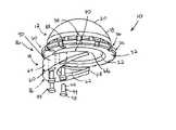
- FIG. 1is an exploded view of the acetabular component of the present invention.
- FIG. 2is a bottom view of an assembled acetabular component of FIG. 1 .
- FIG. 3is a cross-sectional view taken through lines A—A of FIG. 2 .
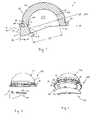
- FIG. 4is an exploded view of an alternate embodiment of the acetabular component of the present invention.
- FIG. 5is another exploded view of the acetabular component of FIG. 4 .
- FIG. 6is a bottom view of an assembled acetabular component of FIG. 4 .
- FIG. 8is an enlarged view taken along circular lines A—A of FIG. 7 .
- FIG. 9is an exploded view of an alternate embodiment of the acetabular component of the present invention.
- FIG. 10is another exploded view of the acetabular component of FIG. 9 .
- FIG. 11is a bottom view of an assembled acetabular component of FIG. 9 .
- FIG. 12is a cross-sectional view taken through lines A—A of FIG. 11 .
- the acetabular component 10generally consists of an acetabular articulating component 12 and an acetabular constraining component 14 .
- Acetabular component 10can be used as an acetabular insert that connects with a separate acetabular shell or without the shell and adapted to function simultaneously as both a shell and insert.
- the acetabular componentfor example, can be cemented and/or screw retained in the natural acetabulum of a patient.
- Articulating component 12generally has a hemispherical or dome shaped body 18 with an outer surface 20 and inner surface 22 .
- the inner surface 22defines a hemispherical cavity 24 for receiving a femoral ball of a femoral hip stem.
- Inner surface 22has a concave shape with a smooth articulating wall or surface adapted to articulate with the femoral ball.
- the outer surface 20has a hemispherical or dome shape with a smooth surface that is adapted to engage an inner surface of an acetabular shell.
- An annular rim 26extends around an outer perimeter of the articulating component along a base portion 30 .
- This base portionincludes a distal end with an annular platform or ring-shaped surface 32 that provides an entrance way or opening into the cavity 24 of the articulating component 12 .
- Platform 32has a planar surface that circumferentially extends around the entire base portion.
- a sloped ledge or shoulder 34( FIG. 3 ) is adjacent platform 32 and forms a transition into cavity 24 .
- a first set of notches or recesses 36is evenly spaced circumferentially around an outer edge of base portion 30 .
- a second set of notches or recesses 38is evenly spaced circumferentially around outer surface 20 and above notches 36 .
- Notches 38are adapted to engage and lock with the shell. Both sets of notches have polygonal shapes, but these notches can have various shapes and sizes known in the art.
- the articulating component 12can have various configurations and connect to an acetabular shell in various ways.
- the articulating componentcan be spherical, hemispherical, or other shapes.
- U.S. Pat. No. 6,129,765 entitled “Locking Mechanism for Acetabular Cup” to Lopez et al.teaches a locking mechanism for an acetabular cup and is fully incorporated herein by reference.
- component 14has a body 60 with a half moon wedge shape. From a bottom view ( FIG. 2 ), body 60 generally forms a semi-circular or partial ring shape.
- Body 60has a circular inner wall 62 and a circular outer wall 64 . These walls are separated to provide the body with a width “W” shown in FIG. 3 . This width is generally equal to the width of platform 32 on the base portion 30 of the articulating component 12 .
- walls 62 and 64have a smooth surface with a spherical contour.
- Two ends 66 and 68form an end of a tapered portion of body 60 .
- Body 60has a top wall or surface 70 formed as a partial annular or circular platform.
- Surface 70is planar and adapted to seat against platform 32 .
- a lip 71(shown in FIG. 3 ) extends upwardly from surface 70 and forms part of the spherical contour of inner wall 62 .
- surface 70is shaped and sized to correspond to the shape and size of platform 32 .
- a bottom wall or surface 72is oppositely disposed from surface 70 . From a bottom view, this surface 72 has a partial annular or circular shape. From a side view, this surface 72 has a tapered or sloped shape.
- a planar surface 74is adjacent surface 72 on one side, and sloped surface 75 is adjacent surface 72 on another side.
- body 60has a triangular shape.
- the bodyhas a constant, gradual, and symmetric taper from a radial edge 76 to ends 66 and 68 .
- articulating component 12forms a hemisphere.
- Platform 32 of base portion 30extends along a hemispherical dashed line H—H.
- Surface 70 of constraining component 14seats against platform 32 . Both of these surfaces are planar and form a flush contact.
- Constraining component 14forms an extension to articulating component 12 .
- Body 60extends below the hemispherical line H—H when the articulating and constraining components are connected together to form an acetabular component 10 having more than a hemisphere. More particularly, as shown in FIG. 3 , inner surface 22 of articulating component 12 forms a spherical cavity.
- Inner wall 62 of constraining component 14forms a partial spherical surface that provides a continuous spherical extension to surface 20 .
- This extensionextends below line H—H and captures and retains the femoral ball of a femoral hip stem.
- the interface 80 between surface 22 and wall 62is smooth, uninterrupted, and seamless.
- a locking mechanism 86connects the constraining component 14 to the articulating component 12 .
- a first set of bores 88extends into the platform 32 of base portion 30 of the articulating component. Preferably, these bores are cylindrical and partially extend into the body 60 but not through the body.
- a second set of bores 90extends into and through constraining component 14 . Bores 90 extend through surfaces 70 and 72 . Further, preferably these bores 90 are cylindrical to match the size and shape of bores 88 .
- a screw, post, connector or other device 94can be positioned through both sets of bores to hold the components together.
- Connector 94has an elongated cylindrical shaft portion 96 with a head portion 98 .
- Shaft portion 96can have external threads adapted to threadably engage threads located inside bores 88 .
- head portion 98can have a recess, indentation, or other means adapted to engage a tool for inserting the connectors into or removing the connectors from bores 88 and 90 .
- the locking mechanism 86can have various configurations to perform the function of connecting the constraining component to the articulating component. This locking mechanism can be adapted to permanently connect the constraining component to the articulating component or removeably connect these two components.
- Constraining component 14is adapted to constrain or capture the femoral ball within the cavity 24 of the articulating component 12 .
- the body 60 of the constraining componentdoes not fully extend circumferentially around the base portion 30 of the articulating component.
- Body 60can be rotationally positioned around the base portion 30 and then attached to the articulating component to constrain the femoral ball. The position of the constraining component captures the femoral ball yet does not impede the range of motion of the hip stem.
- FIGS. 4–8show another embodiment of an acetabular component 100 that consists of an acetabular articulating component 112 and an acetabular constraining component 114 .
- Components 112 and 114are generally similar to the articulating component 12 and constraining component 14 , respectively, described in connection with FIGS. 1–3 , and reference should be made to these figures for a description of components 112 and 114 .
- One difference between components 112 and 114 and components 12 and 14is the locking mechanism.
- acetabular component 100includes a locking mechanism 116 that connects the constraining component 114 to the articulating component 112 .
- a set of bores 120extends into the platform 122 of base portion 126 of the articulating component 112 .
- these boresare cylindrical and partially extend into the body 130 but not through the body.
- these boreshave a first cylindrical section 132 and a second cylindrical section 134 .
- Section 134has a diameter greater than section 132 to form a cylindrical capture.
- Constraining component 114includes a plurality of posts or projections 150 . These projections extend upwardly from surface 152 and are equally and circumferentially spaced about surface 152 . As best shown in FIG. 8 , preferably, each post generally has a cylindrical shape with a first cylindrical section 154 or stem section and a second cylindrical section 156 or head section. Section 156 has a diameter greater than section 154 to form an enlarged head.
- the bores 120align with corresponding posts 150 .
- the postsare shaped, sized, and spaced to engage or fit into bores 120 .
- section 156is captured in section 134 .
- Posts 150then, can be adapted to snappingly engage in bores 120 .
- the locking mechanism 116can have various configurations to perform the function of connecting the constraining component to the articulating component. This locking mechanism can be adapted to permanently connect the constraining component to the articulating component or removeably connect these two components.
- the posts 150can be integrally formed with surface 152 or separate (similar to the exemplary embodiment shown in FIG. 1 ). Further, the posts are connected to the constraining component, and the bores are in the articulating component. The posts and bores can be switched. Specifically, the posts can be formed as part of the articulating component, and the bores formed as part of the constraining component.
- FIGS. 9–12show another embodiment of an acetabular component 200 that consists of an acetabular articulating component 212 and an acetabular constraining component 214 .
- Components 212 and 214are generally similar to the articulating component 12 and constraining component 14 , respectively, described in connection with FIGS. 1–3 , and reference should be made to these figures for a description of components 212 and 214 .
- One difference between components 212 and 214 and components 12 and 14is the locking mechanism.
- acetabular component 200includes a locking mechanism 216 that connects the constraining component 214 to the articulating component 212 .
- a set of passages 220extends into the platform 222 of base portion 226 of the articulating component 212 .
- these passageshave a polygonal shape (such as square or rectangular) and completely extend through base portion 226 and body 230 .
- An elongated rectangular channel or recess 240extends partially into the outer surface 242 of articulating component 212 .
- Constraining component 214includes a plurality of posts or projections 250 . These projections extend upwardly from surface 252 and are equally and circumferentially spaced about surface 252 .
- each postgenerally has a rectangular shape with a first rectangular section 254 or stem section and a second rectangular section 256 or head section.
- Section 256has an enlarged head with a triangular shape from a side view. This head has a sloped surface 260 , a flat surface section 262 , and a flat bottom surface 264 .
- the passages 220align with corresponding posts 250 .
- the postsare shaped, sized, and spaced to engage passages 220 .
- section 256fits through a corresponding passage 220 until surface 264 engages on a top surface 270 of base portion 226 , and the posts reside in channels 240 of outer surface 242 .
- Section 256can be adapted to snappingly engage through passages 220 .
- the locking mechanism 216can have various configurations to perform the function of connecting the constraining component to the articulating component. This locking mechanism can be adapted to permanently connect the constraining component to the articulating component or removeably connect these two components.
- the locking mechanismenables the constraining component to connect to the articulating component. This connection can be removeable so the constraining component can be attached, detached, and re-attached to the articulating component.
- the constraining componentcan be positioned in a variety of different positions around the base portion of the articulating component.
- the base portioncan include a plurality of bores or passages that circumferentially extend completely around the base portion or partially around the base portion.
- the constraining componentcan be attached in a plurality of different circumferential positions around the articulating component.
Landscapes
- Health & Medical Sciences (AREA)
- Orthopedic Medicine & Surgery (AREA)
- Cardiology (AREA)
- Oral & Maxillofacial Surgery (AREA)
- Transplantation (AREA)
- Engineering & Computer Science (AREA)
- Biomedical Technology (AREA)
- Heart & Thoracic Surgery (AREA)
- Vascular Medicine (AREA)
- Life Sciences & Earth Sciences (AREA)
- Animal Behavior & Ethology (AREA)
- General Health & Medical Sciences (AREA)
- Public Health (AREA)
- Veterinary Medicine (AREA)
- Prostheses (AREA)
Abstract
Description
Claims (16)
Priority Applications (5)
| Application Number | Priority Date | Filing Date | Title |
|---|---|---|---|
| US10/613,330US7022142B2 (en) | 2003-07-03 | 2003-07-03 | Constrained acetabular liner |
| CA002471779ACA2471779C (en) | 2003-07-03 | 2004-06-21 | Constrained acetabular liner |
| EP04253741.5AEP1506749B1 (en) | 2003-07-03 | 2004-06-23 | Constrained acetabular liner |
| AU2004202926AAU2004202926B2 (en) | 2003-07-03 | 2004-06-29 | Constrained acetabular liner |
| JP2004197066AJP2005021699A (en) | 2003-07-03 | 2004-07-02 | Restrained acetabular liner |
Applications Claiming Priority (1)
| Application Number | Priority Date | Filing Date | Title |
|---|---|---|---|
| US10/613,330US7022142B2 (en) | 2003-07-03 | 2003-07-03 | Constrained acetabular liner |
Publications (2)
| Publication Number | Publication Date |
|---|---|
| US20050004677A1 US20050004677A1 (en) | 2005-01-06 |
| US7022142B2true US7022142B2 (en) | 2006-04-04 |
Family
ID=33552667
Family Applications (1)
| Application Number | Title | Priority Date | Filing Date |
|---|---|---|---|
| US10/613,330Expired - LifetimeUS7022142B2 (en) | 2003-07-03 | 2003-07-03 | Constrained acetabular liner |
Country Status (5)
| Country | Link |
|---|---|
| US (1) | US7022142B2 (en) |
| EP (1) | EP1506749B1 (en) |
| JP (1) | JP2005021699A (en) |
| AU (1) | AU2004202926B2 (en) |
| CA (1) | CA2471779C (en) |
Cited By (20)
| Publication number | Priority date | Publication date | Assignee | Title |
|---|---|---|---|---|
| US7445639B2 (en) | 2001-02-23 | 2008-11-04 | Biomet Manufacturing Corp. | Knee joint prosthesis |
| US7497874B1 (en) | 2001-02-23 | 2009-03-03 | Biomet Manufacturing Corp. | Knee joint prosthesis |
| US20090192626A1 (en)* | 2008-01-25 | 2009-07-30 | Depuy Products, Inc. | Constraining ring inserter |
| US20100268348A1 (en)* | 2009-04-20 | 2010-10-21 | Michael D. Ries | Acetabular Cup |
| US20110230950A1 (en)* | 2008-09-16 | 2011-09-22 | Tracey Knapp | Stent |
| US8157869B2 (en) | 2007-01-10 | 2012-04-17 | Biomet Manufacturing Corp. | Knee joint prosthesis system and method for implantation |
| US8163028B2 (en) | 2007-01-10 | 2012-04-24 | Biomet Manufacturing Corp. | Knee joint prosthesis system and method for implantation |
| US20120116527A1 (en)* | 2009-04-24 | 2012-05-10 | DePul International Limited | Surgical prostheses |
| US8187280B2 (en) | 2007-10-10 | 2012-05-29 | Biomet Manufacturing Corp. | Knee joint prosthesis system and method for implantation |
| US20120283840A1 (en)* | 2009-02-24 | 2012-11-08 | Phillip Frederick | Methods and apparatus for fai surgeries |
| US8308812B2 (en) | 2006-11-07 | 2012-11-13 | Biomedflex, Llc | Prosthetic joint assembly and joint member therefor |
| US8328873B2 (en) | 2007-01-10 | 2012-12-11 | Biomet Manufacturing Corp. | Knee joint prosthesis system and method for implantation |
| US8512413B2 (en) | 2006-11-07 | 2013-08-20 | Biomedflex, Llc | Prosthetic knee joint |
| US8562616B2 (en) | 2007-10-10 | 2013-10-22 | Biomet Manufacturing, Llc | Knee joint prosthesis system and method for implantation |
| US8828009B2 (en) | 2010-08-26 | 2014-09-09 | Smith & Nephew, Inc. | Implants, surgical methods, and instrumentation for use in femoroacetabular impingement surgeries |
| US9005307B2 (en) | 2006-11-07 | 2015-04-14 | Biomedflex, Llc | Prosthetic ball-and-socket joint |
| US9060862B2 (en) | 2011-07-08 | 2015-06-23 | Floyd Franklin Castro | Semi-constrained ball and socket joints |
| US9566157B2 (en) | 2006-11-07 | 2017-02-14 | Biomedflex, Llc | Three-member prosthetic joint |
| US20220183848A1 (en)* | 2019-12-11 | 2022-06-16 | Depuy Ireland Unlimited Company | Ceramic acetabular shell liners with augments |
| US11857423B2 (en) | 2021-11-16 | 2024-01-02 | Arthrology Consulting, Llc | Off-center liner for acetabular cup |
Families Citing this family (23)
| Publication number | Priority date | Publication date | Assignee | Title |
|---|---|---|---|---|
| US7597715B2 (en)* | 2005-04-21 | 2009-10-06 | Biomet Manufacturing Corp. | Method and apparatus for use of porous implants |
| US8123814B2 (en) | 2001-02-23 | 2012-02-28 | Biomet Manufacturing Corp. | Method and appartus for acetabular reconstruction |
| US7918896B2 (en)* | 2004-09-15 | 2011-04-05 | Wright Medical Technology, Inc. | Unitary acetabular cup prosthesis with extension for deficient acetabulum |
| US20060226570A1 (en)* | 2005-04-12 | 2006-10-12 | Zimmer Technology, Inc. | Method for making a metal-backed acetabular implant |
| US8292967B2 (en)* | 2005-04-21 | 2012-10-23 | Biomet Manufacturing Corp. | Method and apparatus for use of porous implants |
| US8021432B2 (en) | 2005-12-05 | 2011-09-20 | Biomet Manufacturing Corp. | Apparatus for use of porous implants |
| US8066778B2 (en)* | 2005-04-21 | 2011-11-29 | Biomet Manufacturing Corp. | Porous metal cup with cobalt bearing surface |
| US8266780B2 (en)* | 2005-04-21 | 2012-09-18 | Biomet Manufacturing Corp. | Method and apparatus for use of porous implants |
| US7708783B2 (en)* | 2005-11-04 | 2010-05-04 | Zimmer Technology, Inc. | Rotating constrained liner |
| AU2006335005B2 (en)* | 2006-01-09 | 2009-09-24 | Silesco Pty Ltd | Implantable joint prosthesis |
| US7635447B2 (en)* | 2006-02-17 | 2009-12-22 | Biomet Manufacturing Corp. | Method and apparatus for forming porous metal implants |
| US8308811B2 (en)* | 2006-04-11 | 2012-11-13 | Zimmer, Inc. | Acetabular cup conversion ring |
| US20070239283A1 (en)* | 2006-04-11 | 2007-10-11 | Berger Richard A | Acetabular cup conversion ring |
| AU2007333133B2 (en)* | 2006-12-12 | 2013-07-04 | Exactech, Inc. | Constrained acetabular cup liner locking ring and polyethylene liner congruency feature |
| CN101842062B (en)* | 2007-09-25 | 2013-04-03 | 拜欧米特制造公司 | Method for manufacturing cementless tibial tray |
| US9649194B2 (en)* | 2009-07-10 | 2017-05-16 | Peter Forsell | Hip joint device |
| EP2451388B1 (en)* | 2009-07-10 | 2016-03-30 | Kirk Promotion LTD. | Hip joint device |
| US11039929B2 (en)* | 2009-07-10 | 2021-06-22 | Peter Mats Forsell | Hip joint device and method |
| AU2013241786B2 (en)* | 2012-03-30 | 2017-04-13 | Orthodontic Research And Development, S.L. | Method of assembling a distalizer |
| US10064730B2 (en) | 2015-03-13 | 2018-09-04 | Patrick Birmingham | Method and device for joint replacement |
| WO2020209770A1 (en)* | 2019-04-08 | 2020-10-15 | ÅKESSON, Stig | Collar for preventing dislocation of hip joint prothesis |
| RU2746519C1 (en)* | 2020-06-02 | 2021-04-14 | Анатолий Гериевич Галкин | Acetabular endoprosthesis |
| CN112842629B (en)* | 2020-12-30 | 2022-03-11 | 北京市春立正达医疗器械股份有限公司 | Rebuild acetabular cup of rebuilding acetabular anatomy rotation center |
Citations (7)
| Publication number | Priority date | Publication date | Assignee | Title |
|---|---|---|---|---|
| US4380090A (en)* | 1981-07-24 | 1983-04-19 | Ramos Pedro A | Hip prosthesis |
| US4770661A (en)* | 1982-01-18 | 1988-09-13 | Indong Oh | Conversion femoral endoprosthesis |
| US5002577A (en)* | 1989-08-10 | 1991-03-26 | Boehringer Mannheim Corporation | Variable position acetabular cup |
| US5092897A (en)* | 1990-03-15 | 1992-03-03 | Forte Mark R | Implantable acetabular prosthetic hip joint with universal adjustability |
| US5133763A (en)* | 1987-04-14 | 1992-07-28 | Mullers Jan B | Joint prosthesis |
| US5263988A (en)* | 1991-08-20 | 1993-11-23 | Exactech, Inc. | Bipolar endoprosthesis |
| US5458649A (en)* | 1992-09-02 | 1995-10-17 | Sulzer Medizinaltechnik Ag | Two-part hipjoint socket |
Family Cites Families (14)
| Publication number | Priority date | Publication date | Assignee | Title |
|---|---|---|---|---|
| CH514331A (en)* | 1969-05-23 | 1971-10-31 | Osteo Ag | Hip joint prosthesis |
| FR2395011A1 (en)* | 1977-06-24 | 1979-01-19 | Ducroquet Jean | Artificial implant for repairing hip joint - has hollow cylindrical body with interrupted external thread embedded in iliac bone |
| US4642123A (en) | 1983-03-08 | 1987-02-10 | Joint Medical Products Corporation | Ball and socket bearing for artificial joint |
| CH671687A5 (en) | 1987-03-30 | 1989-09-29 | Sulzer Ag | |
| FR2684544B1 (en)* | 1991-12-04 | 1994-03-25 | Medinov Sa | COTYLOUIDIAN IMPLANT. |
| FR2706285B1 (en)* | 1993-06-17 | 1995-09-01 | Implant Reduction Eurl | Anti-dislocation prosthesis. |
| US5458648A (en)* | 1994-02-24 | 1995-10-17 | Kinetikos Medical, Inc. | Great toe joint implant and method of implantation |
| FR2725359B1 (en)* | 1994-10-11 | 1997-01-24 | Impact | COTYLOID IMPLANT FOR HIP PROSTHESIS |
| DE19716051A1 (en)* | 1997-04-17 | 1997-11-13 | Klueber Dietrich Dr Med | Dislocation guard ring for use on hip endoprotheses and secures to plastic socket by screws |
| US5800555A (en) | 1997-04-24 | 1998-09-01 | Depuy Orthopaedics, Inc. | Acetabular cup bearing liner |
| US5938702A (en) | 1997-10-31 | 1999-08-17 | Sulzer Orthopedics Inc. | Locking mechanism for acetabular cup |
| IT245363Y1 (en)* | 1998-05-12 | 2002-03-20 | Tian Enrico | ANTI-LUXURY ANKLE PROSTHESIS |
| US5989293A (en)* | 1998-07-17 | 1999-11-23 | Bristol-Myers Squibb Co. | Acetabular cup kit for use during hip replacement surgery |
| US20030105526A1 (en)* | 2001-11-30 | 2003-06-05 | Amei Technologies Inc. | High tibial osteotomy (HTO) wedge |
- 2003
- 2003-07-03USUS10/613,330patent/US7022142B2/ennot_activeExpired - Lifetime
- 2004
- 2004-06-21CACA002471779Apatent/CA2471779C/ennot_activeExpired - Fee Related
- 2004-06-23EPEP04253741.5Apatent/EP1506749B1/ennot_activeExpired - Lifetime
- 2004-06-29AUAU2004202926Apatent/AU2004202926B2/ennot_activeCeased
- 2004-07-02JPJP2004197066Apatent/JP2005021699A/enactivePending
Patent Citations (8)
| Publication number | Priority date | Publication date | Assignee | Title |
|---|---|---|---|---|
| US4380090A (en)* | 1981-07-24 | 1983-04-19 | Ramos Pedro A | Hip prosthesis |
| US4380090B1 (en)* | 1981-07-24 | 1993-09-21 | A. Ramos Pedro | Hip prosthesis |
| US4770661A (en)* | 1982-01-18 | 1988-09-13 | Indong Oh | Conversion femoral endoprosthesis |
| US5133763A (en)* | 1987-04-14 | 1992-07-28 | Mullers Jan B | Joint prosthesis |
| US5002577A (en)* | 1989-08-10 | 1991-03-26 | Boehringer Mannheim Corporation | Variable position acetabular cup |
| US5092897A (en)* | 1990-03-15 | 1992-03-03 | Forte Mark R | Implantable acetabular prosthetic hip joint with universal adjustability |
| US5263988A (en)* | 1991-08-20 | 1993-11-23 | Exactech, Inc. | Bipolar endoprosthesis |
| US5458649A (en)* | 1992-09-02 | 1995-10-17 | Sulzer Medizinaltechnik Ag | Two-part hipjoint socket |
Cited By (34)
| Publication number | Priority date | Publication date | Assignee | Title |
|---|---|---|---|---|
| US7497874B1 (en) | 2001-02-23 | 2009-03-03 | Biomet Manufacturing Corp. | Knee joint prosthesis |
| US7445639B2 (en) | 2001-02-23 | 2008-11-04 | Biomet Manufacturing Corp. | Knee joint prosthesis |
| US9566157B2 (en) | 2006-11-07 | 2017-02-14 | Biomedflex, Llc | Three-member prosthetic joint |
| US9107754B2 (en) | 2006-11-07 | 2015-08-18 | Biomedflex, Llc | Prosthetic joint assembly and prosthetic joint member |
| US9005307B2 (en) | 2006-11-07 | 2015-04-14 | Biomedflex, Llc | Prosthetic ball-and-socket joint |
| US8512413B2 (en) | 2006-11-07 | 2013-08-20 | Biomedflex, Llc | Prosthetic knee joint |
| US8308812B2 (en) | 2006-11-07 | 2012-11-13 | Biomedflex, Llc | Prosthetic joint assembly and joint member therefor |
| US8328873B2 (en) | 2007-01-10 | 2012-12-11 | Biomet Manufacturing Corp. | Knee joint prosthesis system and method for implantation |
| US8157869B2 (en) | 2007-01-10 | 2012-04-17 | Biomet Manufacturing Corp. | Knee joint prosthesis system and method for implantation |
| US8163028B2 (en) | 2007-01-10 | 2012-04-24 | Biomet Manufacturing Corp. | Knee joint prosthesis system and method for implantation |
| US8936648B2 (en) | 2007-01-10 | 2015-01-20 | Biomet Manufacturing, Llc | Knee joint prosthesis system and method for implantation |
| US8480751B2 (en) | 2007-01-10 | 2013-07-09 | Biomet Manufacturing, Llc | Knee joint prosthesis system and method for implantation |
| US8187280B2 (en) | 2007-10-10 | 2012-05-29 | Biomet Manufacturing Corp. | Knee joint prosthesis system and method for implantation |
| US10736747B2 (en) | 2007-10-10 | 2020-08-11 | Biomet Manufacturing, Llc | Knee joint prosthesis system and method for implantation |
| US8562616B2 (en) | 2007-10-10 | 2013-10-22 | Biomet Manufacturing, Llc | Knee joint prosthesis system and method for implantation |
| US9763793B2 (en) | 2007-10-10 | 2017-09-19 | Biomet Manufacturing, Llc | Knee joint prosthesis system and method for implantation |
| US20090192626A1 (en)* | 2008-01-25 | 2009-07-30 | Depuy Products, Inc. | Constraining ring inserter |
| US8535323B2 (en) | 2008-01-25 | 2013-09-17 | DePuy Synthes Products, LLC | Constraining ring inserter |
| US8764847B2 (en)* | 2008-09-16 | 2014-07-01 | C. R. Bard, Inc. | Stent |
| US20110230950A1 (en)* | 2008-09-16 | 2011-09-22 | Tracey Knapp | Stent |
| US8900320B2 (en)* | 2009-02-24 | 2014-12-02 | Smith & Nephew, Inc | Methods and apparatus for FAI surgeries |
| US20120283840A1 (en)* | 2009-02-24 | 2012-11-08 | Phillip Frederick | Methods and apparatus for fai surgeries |
| US9504577B2 (en) | 2009-02-24 | 2016-11-29 | Smith & Nephew, Inc. | Methods and apparatus for FAI surgeries |
| US20100268348A1 (en)* | 2009-04-20 | 2010-10-21 | Michael D. Ries | Acetabular Cup |
| US8211184B2 (en) | 2009-04-20 | 2012-07-03 | Michael D. Ries | Acetabular cup |
| US8574306B2 (en) | 2009-04-20 | 2013-11-05 | Michael D. Ries | Acetabular cup |
| US20120116527A1 (en)* | 2009-04-24 | 2012-05-10 | DePul International Limited | Surgical prostheses |
| US8979939B2 (en) | 2009-04-24 | 2015-03-17 | Depuy International Limited | Surgical prostheses |
| US8894717B2 (en)* | 2009-04-24 | 2014-11-25 | Depuy International Limited | Surgical prostheses |
| US8828009B2 (en) | 2010-08-26 | 2014-09-09 | Smith & Nephew, Inc. | Implants, surgical methods, and instrumentation for use in femoroacetabular impingement surgeries |
| US9060862B2 (en) | 2011-07-08 | 2015-06-23 | Floyd Franklin Castro | Semi-constrained ball and socket joints |
| US20220183848A1 (en)* | 2019-12-11 | 2022-06-16 | Depuy Ireland Unlimited Company | Ceramic acetabular shell liners with augments |
| US12274623B2 (en)* | 2019-12-11 | 2025-04-15 | Depuy Ireland Unlimited Company | Ceramic acetabular shell liners with augments |
| US11857423B2 (en) | 2021-11-16 | 2024-01-02 | Arthrology Consulting, Llc | Off-center liner for acetabular cup |
Also Published As
| Publication number | Publication date |
|---|---|
| US20050004677A1 (en) | 2005-01-06 |
| JP2005021699A (en) | 2005-01-27 |
| AU2004202926A1 (en) | 2005-01-20 |
| CA2471779A1 (en) | 2005-01-03 |
| CA2471779C (en) | 2009-08-25 |
| AU2004202926B2 (en) | 2009-08-20 |
| EP1506749B1 (en) | 2017-07-26 |
| EP1506749A2 (en) | 2005-02-16 |
| EP1506749A3 (en) | 2010-03-31 |
Similar Documents
| Publication | Publication Date | Title |
|---|---|---|
| US7022142B2 (en) | Constrained acetabular liner | |
| US7115145B2 (en) | Acetabular component | |
| JP4057068B2 (en) | Lock mechanism for acetabular cup | |
| US6610097B2 (en) | Prosthetic cup assembly which includes components possessing self-locking taper and associated method | |
| US9844439B2 (en) | Multiple bearing humeral prosthesis | |
| AU2002302005B2 (en) | Prosthetic cup assembly having increased assembly congruency | |
| US4770661A (en) | Conversion femoral endoprosthesis | |
| EP1945146B1 (en) | Rotating constrained liner | |
| US5263988A (en) | Bipolar endoprosthesis | |
| US6206929B1 (en) | Bipolar hip prosthesis with locking head | |
| US10307255B1 (en) | Acetabular cup assembly | |
| US7179296B2 (en) | Partially constrained ball and socket | |
| US6042611A (en) | Ball and socket bearing for artificial joint | |
| US20070203583A1 (en) | Method and apparatus for aligning a taper lock connection | |
| CN111194194A (en) | Prosthetic assembly for an improved so-called liner for an acetabular or glenoid cup | |
| US11090163B1 (en) | Interlocking reverse hip prosthesis with removable tapered central post | |
| JP2024543695A (en) | Collision-free dual mobility hip prosthesis |
Legal Events
| Date | Code | Title | Description |
|---|---|---|---|
| AS | Assignment | Owner name:CENTERPULSE ORTHOPEDICS INC., TEXAS Free format text:ASSIGNMENT OF ASSIGNORS INTEREST;ASSIGNOR:JOHNSON, ERIN M.;REEL/FRAME:014284/0170 Effective date:20030423 | |
| AS | Assignment | Owner name:ZIMMER AUSTIN, INC., TEXAS Free format text:CHANGE OF NAME;ASSIGNOR:CENTERPULSE ORTHOPEDICS INC.;REEL/FRAME:016263/0264 Effective date:20040602 | |
| STCF | Information on status: patent grant | Free format text:PATENTED CASE | |
| AS | Assignment | Owner name:ZIMMER, INC., INDIANA Free format text:CHANGE OF NAME;ASSIGNOR:ZIMMER AUSTIN, INC.;REEL/FRAME:017423/0587 Effective date:20060208 | |
| CC | Certificate of correction | ||
| FPAY | Fee payment | Year of fee payment:4 | |
| FEPP | Fee payment procedure | Free format text:PAYOR NUMBER ASSIGNED (ORIGINAL EVENT CODE: ASPN); ENTITY STATUS OF PATENT OWNER: LARGE ENTITY | |
| FPAY | Fee payment | Year of fee payment:8 | |
| MAFP | Maintenance fee payment | Free format text:PAYMENT OF MAINTENANCE FEE, 12TH YEAR, LARGE ENTITY (ORIGINAL EVENT CODE: M1553) Year of fee payment:12 |