US7022117B1 - Customized refractive correction - Google Patents
Customized refractive correctionDownload PDFInfo
- Publication number
- US7022117B1 US7022117B1US10/110,894US11089402AUS7022117B1US 7022117 B1US7022117 B1US 7022117B1US 11089402 AUS11089402 AUS 11089402AUS 7022117 B1US7022117 B1US 7022117B1
- Authority
- US
- United States
- Prior art keywords
- aperture
- card
- profile
- laser
- aperture card
- Prior art date
- Legal status (The legal status is an assumption and is not a legal conclusion. Google has not performed a legal analysis and makes no representation as to the accuracy of the status listed.)
- Expired - Lifetime, expires
Links
Images


Classifications
- A—HUMAN NECESSITIES
- A61—MEDICAL OR VETERINARY SCIENCE; HYGIENE
- A61F—FILTERS IMPLANTABLE INTO BLOOD VESSELS; PROSTHESES; DEVICES PROVIDING PATENCY TO, OR PREVENTING COLLAPSING OF, TUBULAR STRUCTURES OF THE BODY, e.g. STENTS; ORTHOPAEDIC, NURSING OR CONTRACEPTIVE DEVICES; FOMENTATION; TREATMENT OR PROTECTION OF EYES OR EARS; BANDAGES, DRESSINGS OR ABSORBENT PADS; FIRST-AID KITS
- A61F9/00—Methods or devices for treatment of the eyes; Devices for putting in contact-lenses; Devices to correct squinting; Apparatus to guide the blind; Protective devices for the eyes, carried on the body or in the hand
- A61F9/007—Methods or devices for eye surgery
- A61F9/008—Methods or devices for eye surgery using laser
- A61F9/00802—Methods or devices for eye surgery using laser for photoablation
- A61F9/00804—Refractive treatments
- A—HUMAN NECESSITIES
- A61—MEDICAL OR VETERINARY SCIENCE; HYGIENE
- A61F—FILTERS IMPLANTABLE INTO BLOOD VESSELS; PROSTHESES; DEVICES PROVIDING PATENCY TO, OR PREVENTING COLLAPSING OF, TUBULAR STRUCTURES OF THE BODY, e.g. STENTS; ORTHOPAEDIC, NURSING OR CONTRACEPTIVE DEVICES; FOMENTATION; TREATMENT OR PROTECTION OF EYES OR EARS; BANDAGES, DRESSINGS OR ABSORBENT PADS; FIRST-AID KITS
- A61F9/00—Methods or devices for treatment of the eyes; Devices for putting in contact-lenses; Devices to correct squinting; Apparatus to guide the blind; Protective devices for the eyes, carried on the body or in the hand
- A61F9/007—Methods or devices for eye surgery
- A61F9/008—Methods or devices for eye surgery using laser
- A61F9/00802—Methods or devices for eye surgery using laser for photoablation
- A61F9/00817—Beam shaping with masks
- A—HUMAN NECESSITIES
- A61—MEDICAL OR VETERINARY SCIENCE; HYGIENE
- A61F—FILTERS IMPLANTABLE INTO BLOOD VESSELS; PROSTHESES; DEVICES PROVIDING PATENCY TO, OR PREVENTING COLLAPSING OF, TUBULAR STRUCTURES OF THE BODY, e.g. STENTS; ORTHOPAEDIC, NURSING OR CONTRACEPTIVE DEVICES; FOMENTATION; TREATMENT OR PROTECTION OF EYES OR EARS; BANDAGES, DRESSINGS OR ABSORBENT PADS; FIRST-AID KITS
- A61F9/00—Methods or devices for treatment of the eyes; Devices for putting in contact-lenses; Devices to correct squinting; Apparatus to guide the blind; Protective devices for the eyes, carried on the body or in the hand
- A61F9/007—Methods or devices for eye surgery
- A61F9/008—Methods or devices for eye surgery using laser
- A61F2009/00844—Feedback systems
- A61F2009/00846—Eyetracking
- A—HUMAN NECESSITIES
- A61—MEDICAL OR VETERINARY SCIENCE; HYGIENE
- A61F—FILTERS IMPLANTABLE INTO BLOOD VESSELS; PROSTHESES; DEVICES PROVIDING PATENCY TO, OR PREVENTING COLLAPSING OF, TUBULAR STRUCTURES OF THE BODY, e.g. STENTS; ORTHOPAEDIC, NURSING OR CONTRACEPTIVE DEVICES; FOMENTATION; TREATMENT OR PROTECTION OF EYES OR EARS; BANDAGES, DRESSINGS OR ABSORBENT PADS; FIRST-AID KITS
- A61F9/00—Methods or devices for treatment of the eyes; Devices for putting in contact-lenses; Devices to correct squinting; Apparatus to guide the blind; Protective devices for the eyes, carried on the body or in the hand
- A61F9/007—Methods or devices for eye surgery
- A61F9/008—Methods or devices for eye surgery using laser
- A61F2009/00855—Calibration of the laser system
- A—HUMAN NECESSITIES
- A61—MEDICAL OR VETERINARY SCIENCE; HYGIENE
- A61F—FILTERS IMPLANTABLE INTO BLOOD VESSELS; PROSTHESES; DEVICES PROVIDING PATENCY TO, OR PREVENTING COLLAPSING OF, TUBULAR STRUCTURES OF THE BODY, e.g. STENTS; ORTHOPAEDIC, NURSING OR CONTRACEPTIVE DEVICES; FOMENTATION; TREATMENT OR PROTECTION OF EYES OR EARS; BANDAGES, DRESSINGS OR ABSORBENT PADS; FIRST-AID KITS
- A61F9/00—Methods or devices for treatment of the eyes; Devices for putting in contact-lenses; Devices to correct squinting; Apparatus to guide the blind; Protective devices for the eyes, carried on the body or in the hand
- A61F9/007—Methods or devices for eye surgery
- A61F9/008—Methods or devices for eye surgery using laser
- A61F2009/00861—Methods or devices for eye surgery using laser adapted for treatment at a particular location
- A61F2009/00872—Cornea
- A—HUMAN NECESSITIES
- A61—MEDICAL OR VETERINARY SCIENCE; HYGIENE
- A61F—FILTERS IMPLANTABLE INTO BLOOD VESSELS; PROSTHESES; DEVICES PROVIDING PATENCY TO, OR PREVENTING COLLAPSING OF, TUBULAR STRUCTURES OF THE BODY, e.g. STENTS; ORTHOPAEDIC, NURSING OR CONTRACEPTIVE DEVICES; FOMENTATION; TREATMENT OR PROTECTION OF EYES OR EARS; BANDAGES, DRESSINGS OR ABSORBENT PADS; FIRST-AID KITS
- A61F9/00—Methods or devices for treatment of the eyes; Devices for putting in contact-lenses; Devices to correct squinting; Apparatus to guide the blind; Protective devices for the eyes, carried on the body or in the hand
- A61F9/007—Methods or devices for eye surgery
- A61F9/008—Methods or devices for eye surgery using laser
- A61F2009/00878—Planning
- A61F2009/0088—Planning based on wavefront
- A—HUMAN NECESSITIES
- A61—MEDICAL OR VETERINARY SCIENCE; HYGIENE
- A61F—FILTERS IMPLANTABLE INTO BLOOD VESSELS; PROSTHESES; DEVICES PROVIDING PATENCY TO, OR PREVENTING COLLAPSING OF, TUBULAR STRUCTURES OF THE BODY, e.g. STENTS; ORTHOPAEDIC, NURSING OR CONTRACEPTIVE DEVICES; FOMENTATION; TREATMENT OR PROTECTION OF EYES OR EARS; BANDAGES, DRESSINGS OR ABSORBENT PADS; FIRST-AID KITS
- A61F9/00—Methods or devices for treatment of the eyes; Devices for putting in contact-lenses; Devices to correct squinting; Apparatus to guide the blind; Protective devices for the eyes, carried on the body or in the hand
- A61F9/007—Methods or devices for eye surgery
- A61F9/008—Methods or devices for eye surgery using laser
- A61F2009/00878—Planning
- A61F2009/00882—Planning based on topography
Definitions
- the inventionrelates to refractive laser ablation systems, and, more particularly, an excimer laser refractive ablation system employing an aperture card that passes a unique ablation profile.
- Systems for reprofiling the eye for refractive correctionhave become extremely popular. Such systems typically employ a 193-nanometer (nm) argon-fluoride excimer laser, passing the light to the corneal tissue, where a very precise amount of tissue is “ablated” from the eye with a laser shot.
- a variety of delivery mechanismsare commercially used, including systems in which a fixed spot size is moved over the surface of the eye, in which the spot size is varied, and in which erodible masks are placed in the path of the excimer laser beam.
- the ultimate goalis to change the profile of the corneal surface by volumetrically altering the amount of tissue within the cornea.
- PRKphotorefractive keratectomy
- LASIKlaser in situ keratomileusis
- U.S. Pat. No. 5,376,086, issued to Khoobehi et al.discloses a laser surgical method of sculpting a patient's cornea that uses a mask system with multiple openings in which laser power transmission is controlled through the use of diffraction and absorption.
- Each hole in the maskacts like an individual light source, distributing laser power as a function of the hole's size, shape, and overlaid coatings.
- By summing the power output of each hole pattern over a given areaan average power distribution is generated.
- the techniqueis limited because the power transmission of the mask is tailored only to a particular corneal surface by using topographical information of that surface.
- the corneal surface topographic datais the controlling mechanism for constructing the pattern of the mask itself. The surgeon can observe the topographic information and then pattern the mask according to that topographic information.
- the present inventionis directed to improving laser ablation of eye tissue that avoids or reduces shortcomings of previous methods.
- a laser refractive ablation system for the eyesuch as a 193 nm excimer laser system, is implemented to pass a unique “truncated” intensity ablation profile, for example, a non-Gaussian profile or a truncated-Gaussian profile referred to herein as a “soft spot” profile.
- the “top” of the soft spot profileis substantially flattened whereas the sides of the profile slope until an ablation intensity threshold is reached, at which point the edge or sides become nearly vertical.
- the profileis provided using an aperture card prepared based on diffractive effects.
- the aperture cardpreferably includes 1 and 2 millimeter (mm) apertures surrounded by a plurality of extremely small holes referred to herein as “soft spot” apertures that allow the diffractive effect of the laser light to accumulate to form the desired profile. Further, the aperture card includes a “square-sided” profile aperture (referred to herein as a “hard spot” aperture) for testing the fluence of the excimer laser system.
- the aperture cardis intended for a single surgical use because it can exhibit changes in characteristics over time, although in some embodiments, this is not necessarily true.
- the cardis preferably loaded for single use into the system from an aperture card holder, and transported into place using a horizontal and vertical movement robot mechanism. Then, a laser system determines whether the aperture card is properly positioned, inhibiting lasing action if the card is not positioned within tolerance. Alternatively, the laser system can determine the position and adjust the computed ablation profile or otherwise adjust the optical system to adapt for the misalignment of the aperture within the aperture card.
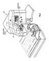
- FIG. 1illustrates a laser refractive ablation system for the eye in accordance with an embodiment of the invention
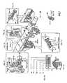
- FIG. 2illustrates the laser system of FIG. 1 that includes an aperture card in accordance with an embodiment of the invention
- FIG. 3illustrates a mechanism for holding an aperture card in place in accordance with an embodiment of the invention
- FIG. 4is another view of the mechanism in FIG. 3 ;
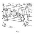
- FIG. 5illustrates a view of a portion of the mechanism of FIG. 3 , including the aperture card of FIG. 2 in accordance with an embodiment of the invention
- FIG. 6illustrates another view of the portion of FIG. 5 with the aperture card of FIG. 2 removed;
- FIG. 7illustrates a mechanism for holding an aperture card in place according to another embodiment of the invention.
- FIG. 8illustrates an alternative position and alignment mechanism for the aperture card corresponding to FIG. 7 ;
- FIG. 9is a mechanical drawing illustrating an aperture mask that forms a portion of an aperture card in accordance with an embodiment of the invention.
- FIG. 10illustrates a square-sided spatial intensity profile of an aperture having a square edge that forms part of the aperture mask of FIG. 7 in accordance with an embodiment of the invention
- FIG. 11illustrates a “soft” spot aperture in accordance with an embodiment of the invention
- FIG. 12illustrates a useful ablation profile passed by a soft spot aperture in accordance with an embodiment of the invention
- FIG. 13illustrates a comparison between a square profile and a soft spot profile in accordance with an embodiment of the invention.
- FIG. 14illustrates a comparison between a square profile and a soft spot profile with their resulting tissue ablation profiles.
- an exemplary excimer laser system 10is illustrated in which a unique profile and aperture card handling or conveying system 12 (also referred to as a linear translation module) is shown in accordance with an embodiment of the invention.
- the system 12takes the place of an iris diaphragm for beam dimensioning. It is mounted in a frame between a bending mirror 13 and a scanner block 14 (see FIG. 1 ).
- the excimer laser systemis a typical 193 nm excimer laser system. It includes an excimer laser 15 and operates as a scanning laser system employing mirrors (e.g., galvanometer driven high precision mirrors for 193 nm) to scan the laser beam to appropriate points on the cornea in a treatment plane 16 .
- mirrorse.g., galvanometer driven high precision mirrors for 193 nm
- the laser system 10employs an eye tracking system with a tracking speed of at least 100 Hz.
- the laser system 10is controlled by a control system 17 , for example, a computer.
- the control systemeither can compute locally a shot pattern to achieve a desired ablation profile, or can receive an ablation profile remotely, such as according to U.S. Pat. No. 5,891,132 entitled “Distributed Excimer Laser Surgery System,” and issued to Hohla. Such systems will be understood by those skilled in the art. Further, other lasers than excimer lasers may be used.
- the systemis implemented to receive an aperture card or application card 100 as shown in FIG. 2 .
- the card 100is precisely positioned within the laser path of the excimer laser system to pass light through apertures forming part of the aperture card.
- the aperture cardis a mask holder similar to a card-based system for chip card designs that includes a set of several high precision drillings used as reference points to the geometrical assembly of the card. The accuracy of these devices is typically down to less than 30 microns on both axes, and manufacturing processes can be automated and checked by microscopic measuring tools.
- the aperture cardis positioned and aligned via pressure points and fixation points in conjunction with precision machining and manufacturing. This produces single use card positioning with a repeatable accuracy in the order of 5 ⁇ m or better.
- FIG. 3an aperture card system 12 is illustrated according to an embodiment of the invention.
- FIG. 4shows another view of the aperture card system 12 .
- Arrow 101shows the direction in which the card 100 is inserted into the system 12 , preferably from a sleeve or holder (not shown) that protects the aperture card 100 and keeps it clean.
- the aperture card 100is fed in a first orientation, for example, laterally, to card catchment or receiving machinery 103 (e.g., a lateral loading mechanism) by hand through a slot 102 , although, in other embodiments, this can be automated.
- card catchment or receiving machinery 103e.g., a lateral loading mechanism
- the card catchment machinery 103pulls the aperture card 100 inside the laser system 10 .
- a pickup-and positioning sled 104(e.g., a vertical loading mechanism) moves forward to the card catchment machinery 103 , as generally indicated by arrow 101 ′ in FIG. 3 , which transfers the aperture card 100 over to the pickup-and positioning sled 104 .
- the pickup-and positioning sled 104moves backwards, generally indicated by arrow 101 ′′ in FIG. 3 , to a desired diaphragm position, and loads the aperture card 100 in a second orientation, for example, vertically, for accurate positioning and locking (e.g., in a vertical position) in the optical path of the excimer laser 15 by pins, as described below.
- the pickup-and positioning sled 104extracts itself to a place away from the secured card 100 and out of the way of the laser shots.
- the laser treatment procedure of the eyethen can be started.
- FIGS. 3 and 4Also shown in FIGS. 3 and 4 are three positioning holes 105 , which are used to position the card 100 on pins within the laser system 10 , as will be described below.
- an aperture mounting slot 106Near the middle of the card 100 is an aperture mounting slot 106 to hold an aperture mask 108 .
- the mask 108is mounted into the slot 106 of the aperture card 100 , preferably being glued in place.
- the aperture card 100is illustrated positioned, after transfer, in an aperture card holder 200 of the laser system 10 .
- three pins 202pass through the pin holes 105 (see also FIG. 3 ) for precise positioning of the aperture card 100 (one pin 202 is obscured from view in FIG. 3 and all are obscured in FIG. 4 ).
- an alignment hole 204shown in FIGS. 3–5 , is provided for reference by lasers alignment within the excimer laser system 10 to align the aperture card 100 within the system before the aperture card 100 is employed. The laser system determines whether the aperture card 100 is properly positioned, inhibiting lasing action if the card is not positioned within tolerance.
- the laser system 10can determine the position and adjust the computed ablation profile or otherwise adjust the optical system to adapt for the misalignment of the aperture within the aperture card.
- FIG. 6illustrates the pins 202 in more detail along with clips 208 used to hold the aperture card 100 (not shown in FIG. 5 ) in place in the aperture card holder 200 . It will be apparent to those skilled in the art that variations on this embodiment could be used to mount the aperture card 100 in position, including, for example, a different number of pins like the pins 202 and a different number of holes in the card 100 like the holes 104 .
- FIG. 7shows a preferred aperture card system 220 having a common structure, in part, with the aperture card system 12 in FIGS. 3 and 4 .
- the primary distinctionresides in the replacement of the alignment pins 202 ( FIG. 5 ) and corresponding alignment holes 105 in the aperture card 100 with fixation points 222 and pressure points 224 x , 224 y as shown in FIG. 8 .
- the fixation points 222comprise three hardened cylinder pins that are press fit into the card holder 26 with high accuracy.
- the card 100is pushed into the holder 226 from right to left (as viewed in FIG. 8 ) until the left edge 227 of the card touches fixation point 222 x and the bottom edge 229 of the card touches fixation points 222 y1 , and 222 y2 .
- the cardis fixated against the fixation points by pressure points 224 x , 224 y which, preferably, are springs.
- the mask 108is preferably constructed of an opaque coating (e.g., chromium deposited or otherwise coated or layered) on quartz. More preferably, the coating is a multilayer coating including a layer of titanium overlaying the chromium layer, and a layer of gold overlaying the titanium layer. Most preferably, the multilayer coating consists of a chromium layer approximately 80 nm thick adjacent the substrate, a titanium layer approximately 40 nm thick adjacent the chromium layer, and a gold layer approximately 80 nm. thick adjacent the titanium layer. The aforementioned layered coating advantageously reduces unwanted reflection of laser light.
- an opaque coatinge.g., chromium deposited or otherwise coated or layered
- the coatingis a multilayer coating including a layer of titanium overlaying the chromium layer, and a layer of gold overlaying the titanium layer.
- the multilayer coatingconsists of a chromium layer approximately 80 nm thick adjacent the substrate, a titanium layer approximately 40 nm thick adjacent the chrom
- the maskincludes a 2 mm effective diameter (or substantially 2 mm effective diameter) “soft spot” (defined in more detail below) aperture, a similar 1 mm (or substantially 1 mm effective diameter) soft spot aperture, and a center, 2 mm effective diameter (or substantially 2 mm) “hard” aperture having a square edge.
- patterning of the mask 108is independent of eye topography data and can be used for any eye topographical surface, including any corneal surface.
- the actual overall diameter of the apertures referred to abovemay be larger or smaller than the corresponding image or irradiance pattern projected onto an eye.
- typical illustratively useful 2 mm diameter and 1 mm diameter spots on the eyecan correspond to 3 mm and 1.5 mm overall diameter aperture patterns, respectively.
- the “hard” square edge apertureis used for fluence testing with a standard fluence plate, such as a polyethylene foil coated on both sides with aluminum. It is preferable to perform the fluence test with a square edge aperture for system calibration because it is easier to see how many shots are required to ablate through material from one layer to the next or to penetrate to a particular depth using a square edge profile beam than it is with the rounded profile ablation of a non-square edge aperture.
- an aperture mask 300which is exemplary of the aperture mask 108 that can fit into the aperture slot 106 , and preferably glued into place.
- a “hard”-edged, center aperture 302has an overall diameter of 3 mm or substantially 3 mm that simply passes a standard square-sided (i.e., square-profiled) laser shot, such as that shown in FIG. 10 .
- a 3 mm overall diameter soft spot aperture 304includes a center aperture area 305 surrounded by a pattern of microscopically small holes 306 that, through direct diffractive effects, create the appropriate ablation profile.
- a third soft spot aperture 307is 1.5 mm or substantially 1.5 mm in overall diameter, which also includes a center aperture area 308 and small microscopic holes 309 similar to those of the aperture 304 to create the appropriate ablation profile, an exemplary embodiment of which is discussed below in connection with FIG. 11 .
- FIG. 9illustrates the aperture mask 300 having a single 3 mm diameter hard edged aperture, a 3 mm diameter soft spot aperture, and a 1.5 mm diameter soft spot aperture, it is contemplated that more or less of these numbers and types, and possibly different diameters, of these apertures could be included in the aperture mask 300 , all of which are included within the scope and spirit of the present invention.
- these aperturestypically are projected onto the eye either reduced or enlarged; here, the 3 mm diameter and 1.5 mm diameter apertures preferably create 2 mm diameter and 1 mm diameter spots on the eye.
- the card holder 200moves (e.g., laterally), according to the desired excimer laser system, to employ a fluence test (in which case the 3 mm center square profile aperture 302 is placed into position) and then for the laser ablations of the eye, either the soft spot aperture 304 (e.g., 2 mm imaged spot or 307 (e.g., 1 mm imaged spot is placed into position.
- the soft spot aperturesare employed in laser ablating by laterally moving the aperture card 100 (e.g., left and right) within the aperture card holder 200 .
- the soft spot apertures 304 and 307 of FIG. 9are focused by the system 10 , preferably down to 2 mm and 1 mm or substantially those values, respectively.
- the apertures 302 , 304 , and 307are preferably formed on a quartz plate 308 , using a suitably deposited mask as described herein.
- the maskcan then be appropriately etched using a laser etching system, as will be appreciated by those skilled in the art.
- photolithography, silicon wafer technology, chip card technology, or other techniquescan be employed to create the mask 300 .
- FIG. 11is a more detailed illustration of an exemplary soft spot aperture 350 that can be used for the soft spot apertures 304 or 307 .
- the soft spot aperture 350is shown having a central open aperture 352 like the apertures 305 and 308 of FIG. 9 , surrounded by microscopic holes 354 like the holes 306 and 309 .
- a variety of known techniquescan be employed to design and position the holes, and knowledgeable artisans would be able to create such an aperture.
- a soft spot aperture that would produce such a profile(e.g., like that of FIG. 11 ) can be obtained from Fraunhofer Institut Siliziumtechnologie, Faunhoferstra ⁇ e 1, D-25524 Itzehoe, Germany, and from others.
- a useful ablation profile (or spatial intensity distribution) 400 passed by the soft spot aperture 304is shown in accordance with an embodiment of the invention.
- the profileis normalized and only one-half the profile 400 is illustrated, solely for simplicity of the drawing, it being understood that the full profile 400 would be as if mirrored about the ordinate axis of FIG. 12 .
- the aperture 307would pass a similar, but narrower, profile.
- a center portion 401 of the aperture profile 400is flat or substantially flat, whereas an edge 402 of the profile 400 , continuous with the portion 401 , is rounded.
- the portion 401is preferably symmetric about the radius of the profile and extends across about 60–80%, and, more preferably, across about 65–70% of the profile 400 .
- the profile 400preferably quickly drops off or diminishes as a substantially square, vertical, or truncated edge 406 .
- the ablation threshold and any variations in itare known in the art.
- the amount of energy falling below the threshold for ablationis preferably about 5% or less of the total energy encompassed by the profile 400 .
- the profile 400is non-Gaussian, for example, between square and Gaussian-shaped, or a truncated Gaussian.
- an automatic systemis employed to position the aperture card 100 at the position in which the aperture mask 300 passes an ablation profile with a substantially flat or flattened top, rounded edges, and substantially truncated sides for ablation of corneal tissue.
- the card 100can be laterally moved into positions for laser shots at a larger “soft edged” spot size, a smaller “soft edged” spot size, or at a center portion suitable for adjusting fluence levels.
- One advantage of the profile 400 of FIG. 12is that, by having a “flat” top, a relatively uniform ablation is produced, which assists in steepening the sides of an ablation, although the resulting profile in tissue is more round than for a square profile. This, like for a Gaussian profile, is also advantageous in avoiding a “haze” that can result from square profile ablations.
- the goal in the design and use of the profile 400is to maximize the ablation per shot while avoiding the haze encountered with square profile ablations.
- the width of the flat portion and the amount of energy below threshold, as discussed above,is driven by this goal.
- the rounded and vertical edgesreduce the “stair-step” effect of typical ablations with square-sided ablation profiles, which could affect healing.
- the soft spot profilecombines both the advantages of the Gaussian profile and the square profile.
- the ablation profile 400is designed to be a very small fraction of the overall ablation profile 400 .
- a much larger amount of energyfalls below the ablation threshold.
- the tissuemerely is heated, rather than ablated. Without ablation, the resulting heating diminishes one of the advantages of a 193 nm laser system. It is therefore desirable to reduce this effect because heating may effect a later ablation of the heated tissue or other nearby tissue, or may have other effects, such as producing scarring or opacities.
- the total energy below threshold of the profile 400is preferably limited to reduce heating while maximizing ablation.
- FIG. 13illustrates a comparison of a square profile (e.g., if the aperture 302 or a similar aperture were used to ablate) with the soft aperture profile 400 . Little of the total energy of the profile 400 appears outside the square profile, as indicated by the outside hatched area.
- the profile 400 of FIG. 12has many advantages, including that it uniformly removes nearly all of the eye tissue normally removed by a square-sided ablation profile (e.g., typically within 90%, although other designs, such as 80%, are possible), but its edges are still “rounded,” thereby rounding the tissue removed on each laser shot.
- FIG. 14illustrates a comparison between a square profile 500 with a resulting laser shot ablation profile 504 in eye tissue and a profile 502 like the profile 400 , according to the invention, with its rounded laser shot ablation profile 506 in eye tissue.
- advantagesalso include allowing iris tracking systems to more continuously and accurately track the location of the pupil.
- the aperture mask 300 of FIG. 9may wear out more quickly than a typical diaphragm card using an excimer laser system. This is for a variety of reasons, including the possibility that the quartz employed for the aperture mask 300 will become slightly more opaque over time. Because chromium-on-quartz is the preferred manufacturing technique, it is desirable thus to replace the aperture card with each excimer treatment for a new patient in the interest of surgical precautionary considerations and to achieve the highest quality ablations, in addition to reproducibility.
- the cardcan, for example, be treated with a laser blast or provided with an electronic signature that disables the card from further use.
- the aperture card 100can also incorporate electronic circuitry to provide the laser system 10 information and validation of procedures to be performed.
- the aperture card 100can include an SLE 4428 secure chip memory. This typically is encoded with a variety of data, such as the serial number of the machine (or machines, such as for a laser center) on which the card 100 is validated for use, the number of procedures available with the particular card 100 , what types of treatments are permitted, and perhaps storage of a control number and patient name after the treatment is performed for tracking purposes. With sufficient storage, the actual treatment profiles or iris alignment and verification data could also be included.
- the electronicsprevent use of the excimer laser system without appropriate validation, such as through a PIN number, and prevent extra uses of the card 100 .
- laser beams having the soft spot intensity profile of this inventionare used in a dual-mode, laser surgery system for the eye.
- the eyeis first treated (“shaped”) for primary corneal defects, such as myopia, hyperopia, and astigmatism, using a larger, fixed spot size.
- a smaller fixed spot sizeis used to remove remaining irregularities (“polished”).
- the larger size spotprovides faster treatment.
- the smaller size spotprovides more precision in the treatment of irregular topographies.
- the size of the larger spotis desirably a relatively large fraction of the typical area of the cornea to be subject to ablation.
- the larger spotis typically between about 2 and 3.5 mm, preferably about 2 mm in diameter.
- the smaller spotis typically not larger than about 1 mm in diameter, and is preferably about 1 mm in diameter.
- PCT application No. PCT/EP98/024208a dual spot size system is described that employs 1 mm and 2 mm square profile spot sizes that are scanned over a corneal surface to create a desired ablation profile.
- the 2 mm soft spot aperturecan be used to treat 80% of a desired ablation in a lower resolution first pass and the remaining 20% treated with the 1 mm soft spot aperture in a higher resolution second pass. Other relative percentages are possible.
- the soft aperture spots of the present inventioncan be employed to create any desired ablation profile, and particularly, customized ablation profiles for irregular ablations other than simple myopic, hyperopic, and astigmatic profiles.
- the soft spot apertures of the present inventionin another embodiment, can be employed to create spiral shot patterns and randomized shot patterns using the techniques described in International Patent Publication WO 94/11655 (PCT application PCT/EP95/04028). These techniques can include ablations made with a single, fixed spot size.
- Eye topography systemssuch as the ORBSCAN and ORBSCAN II® by Bausch & Lomb/Orbtek®, Inc., Salt Lake City, Utah, are known in the art.
- Eye topography datapreferably elevation-based eye topography data, including corneal topography data, as well as wavefront sensor data, for example, as disclosed in U.S. Pat. No. 5,777,719, issued to Williams et al., can be used by an eye surgeon or automated for identifying regions of the cornea requiring ablations for vision correction. Such techniques are known to those skilled in the art. These data can be transformed for use in conjunction with the soft spot apertures and the aperture card of the present invention for making ablations in performing customized refractive correction surgery.
Landscapes
- Health & Medical Sciences (AREA)
- Ophthalmology & Optometry (AREA)
- Life Sciences & Earth Sciences (AREA)
- Animal Behavior & Ethology (AREA)
- Optics & Photonics (AREA)
- Surgery (AREA)
- Engineering & Computer Science (AREA)
- Biomedical Technology (AREA)
- Heart & Thoracic Surgery (AREA)
- Vascular Medicine (AREA)
- Physics & Mathematics (AREA)
- Nuclear Medicine, Radiotherapy & Molecular Imaging (AREA)
- General Health & Medical Sciences (AREA)
- Public Health (AREA)
- Veterinary Medicine (AREA)
- Laser Surgery Devices (AREA)
- Eye Examination Apparatus (AREA)
- Glass Compositions (AREA)
- Prostheses (AREA)
- Laser Beam Processing (AREA)
Abstract
Description
Claims (43)
Applications Claiming Priority (3)
| Application Number | Priority Date | Filing Date | Title |
|---|---|---|---|
| DE1999150788DE19950788A1 (en) | 1999-10-21 | 1999-10-21 | Laser beam spatial intensity profile for refractive laser ablation system used in eye surgery, has flat portion extending for larger percentage of profile and rounded edge extending for small percentage of profile |
| DE2000114482DE10014482A1 (en) | 2000-03-23 | 2000-03-23 | Laser beam spatial intensity profile for refractive laser ablation system used in eye surgery, has flat portion extending for larger percentage of profile and rounded edge extending for small percentage of profile |
| PCT/EP2000/010379WO2001028478A2 (en) | 1999-10-21 | 2000-10-20 | Method and apparatus for opthalmic refractive correction |
Publications (1)
| Publication Number | Publication Date |
|---|---|
| US7022117B1true US7022117B1 (en) | 2006-04-04 |
Family
ID=26004990
Family Applications (1)
| Application Number | Title | Priority Date | Filing Date |
|---|---|---|---|
| US10/110,894Expired - LifetimeUS7022117B1 (en) | 1999-10-21 | 2000-10-20 | Customized refractive correction |
Country Status (12)
| Country | Link |
|---|---|
| US (1) | US7022117B1 (en) |
| EP (2) | EP1221921B1 (en) |
| JP (1) | JP2003511208A (en) |
| KR (1) | KR100734338B1 (en) |
| CN (1) | CN1269463C (en) |
| AT (1) | ATE314832T1 (en) |
| AU (1) | AU777228B2 (en) |
| CA (1) | CA2388448C (en) |
| DE (1) | DE60025387T2 (en) |
| ES (1) | ES2256054T3 (en) |
| SG (1) | SG147296A1 (en) |
| WO (1) | WO2001028478A2 (en) |
Cited By (6)
| Publication number | Priority date | Publication date | Assignee | Title |
|---|---|---|---|---|
| US20090264730A1 (en)* | 2008-04-18 | 2009-10-22 | Case Western Reserve University | Magnetic resonance imaging (mri) guided ablation |
| US8049873B2 (en) | 2008-03-19 | 2011-11-01 | Carl Zeiss Meditec Ag | Surgical microscopy system having an optical coherence tomography facility |
| US9265458B2 (en) | 2012-12-04 | 2016-02-23 | Sync-Think, Inc. | Application of smooth pursuit cognitive testing paradigms to clinical drug development |
| US9380976B2 (en) | 2013-03-11 | 2016-07-05 | Sync-Think, Inc. | Optical neuroinformatics |
| US9662010B2 (en) | 2014-09-19 | 2017-05-30 | Carl Zeiss Meditec Ag | Optical system, comprising a microscopy system and an OCT system |
| US20220296418A1 (en)* | 2019-09-10 | 2022-09-22 | Carl Zeiss Meditec Ag | Methods for characterizing a laser beam of a laser processing system, diaphragm assembly and laser processing system |
Families Citing this family (12)
| Publication number | Priority date | Publication date | Assignee | Title |
|---|---|---|---|---|
| DE19938203A1 (en) | 1999-08-11 | 2001-02-15 | Aesculap Meditec Gmbh | Method and device for correcting visual defects in the human eye |
| EP1407520B1 (en)* | 2001-07-18 | 2006-03-29 | Fraunhofer-Gesellschaft zur Förderung der angewandten Forschung e.V. | Beam-shaping element for optical radiation and a method for producing said element |
| US6814729B2 (en)* | 2002-06-27 | 2004-11-09 | Technovision Gmbh | Laser vision correction apparatus and control method |
| CN1306920C (en)* | 2002-06-27 | 2007-03-28 | 博士伦公司 | Devices for laser vision correction |
| DE102006007750A1 (en)* | 2006-02-20 | 2007-08-23 | Wavelight Ag | Method for laser material processing device or micro structuring device for biological and metallic materials, involves inserting specific optical elements in illuminating system around focal position for making possible beam product |
| DE102006036086A1 (en)* | 2006-08-02 | 2008-02-07 | Bausch & Lomb Incorporated | Method and apparatus for calculating a laser shot file for use in a refractive excimer laser |
| EP2150169B1 (en) | 2007-05-17 | 2016-04-06 | AMO Development, LLC | Customized laser epithelial ablation systems |
| CN105286778B (en)* | 2015-09-30 | 2017-02-22 | 深圳艾尼尔角膜工程有限公司 | Cornea location system and location method |
| CN105342749B (en)* | 2015-09-30 | 2017-08-25 | 深圳艾尼尔角膜工程有限公司 | A kind of cornea automatic station-keeping system and method |
| CN112386399B (en)* | 2019-08-12 | 2023-05-09 | 湖南早晨纳米机器人有限公司 | Nanometer surgical robot and manufacturing method thereof |
| RU201585U1 (en)* | 2020-06-11 | 2020-12-22 | федеральное государственное бюджетное образовательное учреждение высшего образования "Ижевский государственный технический университет имени М.Т. Калашникова" | Excimer laser vision correction device |
| CN119896445B (en)* | 2025-03-26 | 2025-06-27 | 视微影像(河南)科技有限公司 | Laser emitting device and ophthalmic system |
Citations (16)
| Publication number | Priority date | Publication date | Assignee | Title |
|---|---|---|---|---|
| US3689894A (en)* | 1970-04-06 | 1972-09-05 | Foto Mem Inc | Image storage and retrieval system |
| EP0257836A1 (en) | 1986-07-31 | 1988-03-02 | Visx Incorporated | Method and apparatus for performing ophthalmic laser surgery |
| EP0280414A1 (en) | 1987-02-02 | 1988-08-31 | Taunton Technologies, Inc. | Sculpture apparatus for correcting curvature of the cornea |
| US4988348A (en)* | 1989-05-26 | 1991-01-29 | Intelligent Surgical Lasers, Inc. | Method for reshaping the cornea |
| US5061342A (en)* | 1990-05-18 | 1991-10-29 | Bausch & Lomb Incorporated | Target domain profiling of target optical surfaces using excimer laser photoablation |
| WO1993025166A1 (en) | 1992-06-10 | 1993-12-23 | Summit Technology, Inc. | Correction of presbyopia by photorefractive keratectomy |
| US5312320A (en)* | 1983-11-17 | 1994-05-17 | Visx, Incorporated | Apparatus for performing ophthalmological surgery |
| EP0619992A1 (en) | 1993-03-17 | 1994-10-19 | Fondazione Centro San Romanello Del Monte Tabor | Support/positioning device for optical filters |
| WO1994025107A1 (en) | 1993-04-20 | 1994-11-10 | Novatec Laser Systems, Inc. | Improved ophthalmic surgical laser and method |
| US5376086A (en) | 1993-10-26 | 1994-12-27 | Khoobehi; Bahram | Laser surgical method of sculpting a patient's cornea and associated intermediate controlling mask |
| EP0714646A1 (en) | 1994-11-30 | 1996-06-05 | Herbert Schwind GmbH & Co. KG | Device for the removal of corneal tissue |
| WO1996021407A1 (en) | 1995-01-11 | 1996-07-18 | Summit Technology, Inc. | Integrated laser reprofiling systems |
| US5571107A (en)* | 1993-10-26 | 1996-11-05 | Shaibani; Sanan B. | Laser surgical apparatus for sculpting a cornea using a diffractive optical element and method of using the same |
| US5777719A (en)* | 1996-12-23 | 1998-07-07 | University Of Rochester | Method and apparatus for improving vision and the resolution of retinal images |
| US6106513A (en)* | 1991-03-08 | 2000-08-22 | Affymetrix, Inc. | Opthalmological surgery technique with active patient data card |
| US6287296B1 (en)* | 1995-11-30 | 2001-09-11 | Herbert Schwind Gmbh & Co. Kg | Device for the removal of tissue from the cornea of an eye |
Family Cites Families (11)
| Publication number | Priority date | Publication date | Assignee | Title |
|---|---|---|---|---|
| US3516720A (en)* | 1968-03-04 | 1970-06-23 | Eastman Kodak Co | Thin film coating for sunglasses |
| FR2276601A1 (en)* | 1974-06-27 | 1976-01-23 | France Etat | TAPE FILTERS AND APPLICATION TO THE MANUFACTURING OF PROTECTIVE GLASSES |
| US4729372A (en)* | 1983-11-17 | 1988-03-08 | Lri L.P. | Apparatus for performing ophthalmic laser surgery |
| DE4232915A1 (en) | 1992-10-01 | 1994-04-07 | Hohla Kristian | Device for shaping the cornea by removing tissue |
| US5409240A (en) | 1992-11-12 | 1995-04-25 | Unilab Bearing Protection Company, Inc. | Seal with self-lubricating contact surface |
| AU7099694A (en)* | 1993-06-04 | 1995-01-03 | Summit Technology, Inc. | Rotatable aperture apparatus and methods for selective photoablation of surfaces |
| FR2715337B1 (en)* | 1993-11-08 | 1996-04-12 | Khalil Hanna | Mask for laser beam, in particular for surface ablation; method and device using such a mask. |
| US5891132A (en) | 1996-05-30 | 1999-04-06 | Chiron Technolas Gmbh Opthalmologische Systeme | Distributed excimer laser surgery system |
| ES2251082T3 (en) | 1997-04-25 | 2006-04-16 | Technolas Gmbh Ophthalmologische Systeme | ABLATION WITH DUAL MODE Ophthalmic LASER. |
| WO1999024796A1 (en)* | 1997-11-06 | 1999-05-20 | Visx, Incorporated | Systems and methods for calibrating laser ablations |
| US6068625A (en)* | 1998-02-12 | 2000-05-30 | Visx Incorporated | Method and system for removing an epithelial layer from a cornea |
- 2000
- 2000-10-20AUAU11427/01Apatent/AU777228B2/ennot_activeExpired
- 2000-10-20CNCNB008146659Apatent/CN1269463C/ennot_activeExpired - Lifetime
- 2000-10-20DEDE60025387Tpatent/DE60025387T2/ennot_activeExpired - Lifetime
- 2000-10-20KRKR1020027005105Apatent/KR100734338B1/ennot_activeExpired - Fee Related
- 2000-10-20JPJP2001531075Apatent/JP2003511208A/ennot_activeAbandoned
- 2000-10-20ATAT00972834Tpatent/ATE314832T1/ennot_activeIP Right Cessation
- 2000-10-20ESES00972834Tpatent/ES2256054T3/ennot_activeExpired - Lifetime
- 2000-10-20EPEP00972834Apatent/EP1221921B1/ennot_activeExpired - Lifetime
- 2000-10-20EPEP05024709Apatent/EP1639973A3/ennot_activeWithdrawn
- 2000-10-20SGSG200402999-7Apatent/SG147296A1/enunknown
- 2000-10-20WOPCT/EP2000/010379patent/WO2001028478A2/enactiveIP Right Grant
- 2000-10-20USUS10/110,894patent/US7022117B1/ennot_activeExpired - Lifetime
- 2000-10-20CACA002388448Apatent/CA2388448C/ennot_activeExpired - Lifetime
Patent Citations (16)
| Publication number | Priority date | Publication date | Assignee | Title |
|---|---|---|---|---|
| US3689894A (en)* | 1970-04-06 | 1972-09-05 | Foto Mem Inc | Image storage and retrieval system |
| US5312320A (en)* | 1983-11-17 | 1994-05-17 | Visx, Incorporated | Apparatus for performing ophthalmological surgery |
| EP0257836A1 (en) | 1986-07-31 | 1988-03-02 | Visx Incorporated | Method and apparatus for performing ophthalmic laser surgery |
| EP0280414A1 (en) | 1987-02-02 | 1988-08-31 | Taunton Technologies, Inc. | Sculpture apparatus for correcting curvature of the cornea |
| US4988348A (en)* | 1989-05-26 | 1991-01-29 | Intelligent Surgical Lasers, Inc. | Method for reshaping the cornea |
| US5061342A (en)* | 1990-05-18 | 1991-10-29 | Bausch & Lomb Incorporated | Target domain profiling of target optical surfaces using excimer laser photoablation |
| US6106513A (en)* | 1991-03-08 | 2000-08-22 | Affymetrix, Inc. | Opthalmological surgery technique with active patient data card |
| WO1993025166A1 (en) | 1992-06-10 | 1993-12-23 | Summit Technology, Inc. | Correction of presbyopia by photorefractive keratectomy |
| EP0619992A1 (en) | 1993-03-17 | 1994-10-19 | Fondazione Centro San Romanello Del Monte Tabor | Support/positioning device for optical filters |
| WO1994025107A1 (en) | 1993-04-20 | 1994-11-10 | Novatec Laser Systems, Inc. | Improved ophthalmic surgical laser and method |
| US5571107A (en)* | 1993-10-26 | 1996-11-05 | Shaibani; Sanan B. | Laser surgical apparatus for sculpting a cornea using a diffractive optical element and method of using the same |
| US5376086A (en) | 1993-10-26 | 1994-12-27 | Khoobehi; Bahram | Laser surgical method of sculpting a patient's cornea and associated intermediate controlling mask |
| EP0714646A1 (en) | 1994-11-30 | 1996-06-05 | Herbert Schwind GmbH & Co. KG | Device for the removal of corneal tissue |
| WO1996021407A1 (en) | 1995-01-11 | 1996-07-18 | Summit Technology, Inc. | Integrated laser reprofiling systems |
| US6287296B1 (en)* | 1995-11-30 | 2001-09-11 | Herbert Schwind Gmbh & Co. Kg | Device for the removal of tissue from the cornea of an eye |
| US5777719A (en)* | 1996-12-23 | 1998-07-07 | University Of Rochester | Method and apparatus for improving vision and the resolution of retinal images |
Cited By (9)
| Publication number | Priority date | Publication date | Assignee | Title |
|---|---|---|---|---|
| US8049873B2 (en) | 2008-03-19 | 2011-11-01 | Carl Zeiss Meditec Ag | Surgical microscopy system having an optical coherence tomography facility |
| US20090264730A1 (en)* | 2008-04-18 | 2009-10-22 | Case Western Reserve University | Magnetic resonance imaging (mri) guided ablation |
| US9480535B2 (en)* | 2008-04-18 | 2016-11-01 | Case Western Reserve University | Magnetic resonance imaging (MRI) guided ablation |
| US9265458B2 (en) | 2012-12-04 | 2016-02-23 | Sync-Think, Inc. | Application of smooth pursuit cognitive testing paradigms to clinical drug development |
| US9380976B2 (en) | 2013-03-11 | 2016-07-05 | Sync-Think, Inc. | Optical neuroinformatics |
| US9662010B2 (en) | 2014-09-19 | 2017-05-30 | Carl Zeiss Meditec Ag | Optical system, comprising a microscopy system and an OCT system |
| US10092179B2 (en) | 2014-09-19 | 2018-10-09 | Carl Zeiss Meditec Ag | System for optical coherence tomography, comprising a zoomable kepler system |
| US20220296418A1 (en)* | 2019-09-10 | 2022-09-22 | Carl Zeiss Meditec Ag | Methods for characterizing a laser beam of a laser processing system, diaphragm assembly and laser processing system |
| US12016798B2 (en)* | 2019-09-10 | 2024-06-25 | Carl Zeiss Meditec Ag | Methods for characterizing a laser beam of a laser processing system, diaphragm assembly and laser processing system |
Also Published As
| Publication number | Publication date |
|---|---|
| SG147296A1 (en) | 2008-11-28 |
| KR100734338B1 (en) | 2007-07-03 |
| KR20020053071A (en) | 2002-07-04 |
| EP1221921B1 (en) | 2006-01-04 |
| DE60025387T2 (en) | 2006-07-06 |
| CN1384729A (en) | 2002-12-11 |
| ES2256054T3 (en) | 2006-07-16 |
| HK1051133A1 (en) | 2003-07-25 |
| EP1639973A3 (en) | 2006-08-16 |
| EP1639973A2 (en) | 2006-03-29 |
| AU1142701A (en) | 2001-04-30 |
| JP2003511208A (en) | 2003-03-25 |
| WO2001028478A2 (en) | 2001-04-26 |
| ATE314832T1 (en) | 2006-02-15 |
| CA2388448A1 (en) | 2001-04-26 |
| EP1221921A2 (en) | 2002-07-17 |
| DE60025387D1 (en) | 2006-03-30 |
| AU777228B2 (en) | 2004-10-07 |
| WO2001028478A3 (en) | 2001-12-27 |
| CN1269463C (en) | 2006-08-16 |
| CA2388448C (en) | 2009-02-10 |
Similar Documents
| Publication | Publication Date | Title |
|---|---|---|
| US7022117B1 (en) | Customized refractive correction | |
| EP1534161B1 (en) | Corneal topography-based target warping | |
| JP3615487B2 (en) | Offset ablation profile for treatment of irregular astigmatism | |
| US7077838B2 (en) | Variable repetition rate firing scheme for refractive laser systems | |
| CA2333054A1 (en) | Patient fixation system and method for laser eye surgery | |
| EP2785294A1 (en) | System and method for ophthalmic surface measurements based on sequential estimates | |
| HK1051133B (en) | Customized refractive correction | |
| WO2024201203A1 (en) | Method for locating visual axis for laser assisted ophthalmic procedure without corneal marking | |
| MXPA01010027A (en) | Offset ablation profiles for treatment of irregular astigmatism |
Legal Events
| Date | Code | Title | Description |
|---|---|---|---|
| AS | Assignment | Owner name:BAUSCH & LOMB INCORPORATED, NEW YORK Free format text:ASSIGNMENT OF ASSIGNORS INTEREST;ASSIGNORS:HOHLA, KRISTIAN;YOUSSEFI, GERHARD;TOENNIES, ROLAND;REEL/FRAME:013331/0886 Effective date:20020829 | |
| STCF | Information on status: patent grant | Free format text:PATENTED CASE | |
| AS | Assignment | Owner name:CREDIT SUISSE, NEW YORK Free format text:SECURITY AGREEMENT;ASSIGNORS:BAUSCH & LOMB INCORPORATED;WP PRISM INC.;B&L CRL INC.;AND OTHERS;REEL/FRAME:020733/0765 Effective date:20080320 Owner name:CREDIT SUISSE,NEW YORK Free format text:SECURITY AGREEMENT;ASSIGNORS:BAUSCH & LOMB INCORPORATED;WP PRISM INC.;B&L CRL INC.;AND OTHERS;REEL/FRAME:020733/0765 Effective date:20080320 | |
| AS | Assignment | Owner name:TECHNOLAS GMBH OPHTHALMOLOGISHE SYSTEME, GERMANY Free format text:ASSIGNMENT OF ASSIGNORS INTEREST;ASSIGNOR:BAUSCH & LOMB INCORPORATED;REEL/FRAME:022542/0156 Effective date:20090120 | |
| FPAY | Fee payment | Year of fee payment:4 | |
| AS | Assignment | Owner name:TECHNOLAS PERFECT VISION GMBH, GERMANY Free format text:CORRECTIVE ASSIGNMENT TO CORRECT THE INCORRECT PATENT NO. 7002117 PREVIOUSLY RECORDED ON REEL 023586 FRAME 0106;ASSIGNOR:TECHNOLAS GMBH OPHTHALMOLOGISCHE SYSTEME;REEL/FRAME:023594/0769 Effective date:20090213 | |
| AS | Assignment | Owner name:TECHNOLAS PERFECT VISION GMBH, GERMANY Free format text:CORRECTIVE ASSIGNMENT TO CORRECT THE USPN 7002117 WAS ENTERED IN ERROR; NEEDS TO BE USPN 7022117 PREVIOUSLY RECORDED ON REEL 026598 FRAME 0206. ASSIGNOR(S) HEREBY CONFIRMS THE MERGER;ASSIGNOR:TECHNOLAS GMBH OPHTHALMOLOGISCHE SYSTEME;REEL/FRAME:026638/0240 Effective date:20091213 | |
| AS | Assignment | Owner name:BAUSCH & LOMB INCORPORATED, NEW YORK Free format text:RELEASE BY SECURED PARTY;ASSIGNOR:CREDIT SUISSE AG, CAYMAN ISLANDS BRANCH;REEL/FRAME:028726/0142 Effective date:20120518 | |
| FPAY | Fee payment | Year of fee payment:8 | |
| AS | Assignment | Owner name:BARCLAYS BANK PLC, AS COLLATERAL AGENT, NEW YORK Free format text:SECURITY AGREEMENT;ASSIGNORS:TECHNOLAS PERFECT VISION GMBH;DR. GERHARD MANN CHEM-PHARM. FABRIK GMBH;REEL/FRAME:036400/0711 Effective date:20150819 | |
| AS | Assignment | Owner name:THE BANK OF NEW YORK MELLON, NEW YORK Free format text:SECURITY INTEREST;ASSIGNOR:TECHNOLAS PERFECT VISION GMBH;REEL/FRAME:043251/0910 Effective date:20170717 | |
| MAFP | Maintenance fee payment | Free format text:PAYMENT OF MAINTENANCE FEE, 12TH YEAR, LARGE ENTITY (ORIGINAL EVENT CODE: M1553) Year of fee payment:12 | |
| AS | Assignment | Owner name:THE BANK OF NEW YORK MELLON, AS COLLATERAL AGENT, NEW YORK Free format text:SECURITY INTEREST;ASSIGNORS:ATON PHARMA, INC.;BAUSCH & LOMB INCORPORATED;BAUSCH & LOMB PHARMA HOLDINGS CORP.;AND OTHERS;REEL/FRAME:045444/0634 Effective date:20180213 Owner name:BARCLAYS BANK PLC, AS COLLATERAL AGENT, NEW YORK Free format text:SECURITY INTEREST;ASSIGNORS:ATON PHARMA, INC.;BAUSCH & LOMB INCORPORATED;BAUSCH & LOMB PHARMA HOLDINGS CORP.;AND OTHERS;REEL/FRAME:045444/0299 Effective date:20180213 Owner name:THE BANK OF NEW YORK MELLON, AS COLLATERAL AGENT, Free format text:SECURITY INTEREST;ASSIGNORS:ATON PHARMA, INC.;BAUSCH & LOMB INCORPORATED;BAUSCH & LOMB PHARMA HOLDINGS CORP.;AND OTHERS;REEL/FRAME:045444/0634 Effective date:20180213 | |
| AS | Assignment | Owner name:THE BANK OF NEW YORK MELLON, AS COLLATERAL AGENT, Free format text:INTELLECTUAL PROPERTY SECURITY AGREEMENT;ASSIGNORS:BAUSCH HEALTH IRELAND LIMITED;BAUSCH HEALTH COMPANIES INC.;BAUSCH HEALTH, CANADA INC.;AND OTHERS;REEL/FRAME:049672/0652 Effective date:20190701 Owner name:THE BANK OF NEW YORK MELLON, AS COLLATERAL AGENT, NEW YORK Free format text:INTELLECTUAL PROPERTY SECURITY AGREEMENT;ASSIGNORS:BAUSCH HEALTH IRELAND LIMITED;BAUSCH HEALTH COMPANIES INC.;BAUSCH HEALTH, CANADA INC.;AND OTHERS;REEL/FRAME:049672/0652 Effective date:20190701 | |
| AS | Assignment | Owner name:THE BANK OF NEW YORK MELLON, AS NOTES COLLATERAL AGENT, NEW YORK Free format text:SECURITY INTEREST;ASSIGNORS:BAUSCH & LOMB IRELAND LIMITED;BAUSCH HEALTH COMPANIES INC.;DR. GERHARD MANN CHEM.-PHARM. FABRIK GMBH;AND OTHERS;REEL/FRAME:057821/0800 Effective date:20211004 | |
| AS | Assignment | Owner name:TECHNOLAS PERFECT VISION GMBH, GERMANY Free format text:RELEASE OF SECURITY INTEREST IN SPECIFIED PATENTS (REEL/FRAME 036400/0711);ASSIGNOR:BARCLAYS BANK PLC;REEL/FRAME:061775/0826 Effective date:20221019 Owner name:BAUSCH & LOMB INCORPORATED, NEW YORK Free format text:RELEASE OF SECURITY INTEREST IN SPECIFIED PATENTS (REEL/FRAME 036400/0711);ASSIGNOR:BARCLAYS BANK PLC;REEL/FRAME:061775/0826 Effective date:20221019 Owner name:LABORATOIRE CHAUVIN S.A.S., FRANCE Free format text:RELEASE OF SECURITY INTEREST IN SPECIFIED PATENTS (REEL/FRAME 045444/0299);ASSIGNOR:BARCLAYS BANK PLC;REEL/FRAME:061779/0001 Effective date:20221019 Owner name:PF CONSUMER HEALTHCARE 1 LLC, DELAWARE Free format text:RELEASE OF SECURITY INTEREST IN SPECIFIED PATENTS (REEL/FRAME 045444/0299);ASSIGNOR:BARCLAYS BANK PLC;REEL/FRAME:061779/0001 Effective date:20221019 Owner name:THE UNITED STATES OF AMERICA, AS REPRESENTED BY THE SECRETARY, DEPARTMENT OF HEALTH AND HUMAN SERVICES, MARYLAND Free format text:RELEASE OF SECURITY INTEREST IN SPECIFIED PATENTS (REEL/FRAME 045444/0299);ASSIGNOR:BARCLAYS BANK PLC;REEL/FRAME:061779/0001 Effective date:20221019 Owner name:TECHNOLAS PERFECT VISION GMBH, GERMANY Free format text:RELEASE OF SECURITY INTEREST IN SPECIFIED PATENTS (REEL/FRAME 045444/0299);ASSIGNOR:BARCLAYS BANK PLC;REEL/FRAME:061779/0001 Effective date:20221019 Owner name:BAUSCH & LOMB INCORPORATED, NEW YORK Free format text:RELEASE OF SECURITY INTEREST IN SPECIFIED PATENTS (REEL/FRAME 045444/0299);ASSIGNOR:BARCLAYS BANK PLC;REEL/FRAME:061779/0001 Effective date:20221019 | |
| AS | Assignment | Owner name:THE UNITED STATES OF AMERICA, AS REPRESENTED BY THE SECRETARY, DEPARTMENT OF HEALTH AND HUMAN SERVICES, MARYLAND Free format text:OMNIBUS PATENT SECURITY RELEASE AGREEMENT (REEL/FRAME 045444/0634);ASSIGNOR:THE BANK OF NEW YORK MELLON;REEL/FRAME:061872/0295 Effective date:20221018 Owner name:TECHNOLAS PERFECT VISION GMBH, GERMANY Free format text:OMNIBUS PATENT SECURITY RELEASE AGREEMENT (REEL/FRAME 045444/0634);ASSIGNOR:THE BANK OF NEW YORK MELLON;REEL/FRAME:061872/0295 Effective date:20221018 Owner name:LABORATOIRE CHAUVIN S.A.S., FRANCE Free format text:OMNIBUS PATENT SECURITY RELEASE AGREEMENT (REEL/FRAME 045444/0634);ASSIGNOR:THE BANK OF NEW YORK MELLON;REEL/FRAME:061872/0295 Effective date:20221018 Owner name:BAUSCH & LOMB INCORPORATED, NEW YORK Free format text:OMNIBUS PATENT SECURITY RELEASE AGREEMENT (REEL/FRAME 045444/0634);ASSIGNOR:THE BANK OF NEW YORK MELLON;REEL/FRAME:061872/0295 Effective date:20221018 Owner name:BAUSCH + LOMB IRELAND LIMITED, IRELAND Free format text:OMNIBUS PATENT SECURITY RELEASE AGREEMENT (REEL/FRAME 057821/0800);ASSIGNOR:THE BANK OF NEW YORK MELLON;REEL/FRAME:061884/0514 Effective date:20221018 Owner name:TECHNOLAS PERFECT VISION GMBH, GERMANY Free format text:OMNIBUS PATENT SECURITY RELEASE AGREEMENT (REEL/FRAME 057821/0800);ASSIGNOR:THE BANK OF NEW YORK MELLON;REEL/FRAME:061884/0514 Effective date:20221018 |