US7022086B2 - Guidewire with encapsulated marker - Google Patents
Guidewire with encapsulated markerDownload PDFInfo
- Publication number
- US7022086B2 US7022086B2US10/152,435US15243502AUS7022086B2US 7022086 B2US7022086 B2US 7022086B2US 15243502 AUS15243502 AUS 15243502AUS 7022086 B2US7022086 B2US 7022086B2
- Authority
- US
- United States
- Prior art keywords
- guidewire
- shaft
- marker member
- marker
- layer
- Prior art date
- Legal status (The legal status is an assumption and is not a legal conclusion. Google has not performed a legal analysis and makes no representation as to the accuracy of the status listed.)
- Expired - Fee Related, expires
Links
Images


Classifications
- A—HUMAN NECESSITIES
- A61—MEDICAL OR VETERINARY SCIENCE; HYGIENE
- A61M—DEVICES FOR INTRODUCING MEDIA INTO, OR ONTO, THE BODY; DEVICES FOR TRANSDUCING BODY MEDIA OR FOR TAKING MEDIA FROM THE BODY; DEVICES FOR PRODUCING OR ENDING SLEEP OR STUPOR
- A61M25/00—Catheters; Hollow probes
- A61M25/01—Introducing, guiding, advancing, emplacing or holding catheters
- A61M25/09—Guide wires
- A61M2025/09166—Guide wires having radio-opaque features
Definitions
- the inventionpertains to guidewires and, more particularly, to guidewires having a structure incorporated therein that is adapted and configured to produce a relatively bright image on a fluoroscopy screen or another imaging technique.
- a wide variety of guidewireshave been developed for medical use, for example, intravascular use. Some of these guidewires have a radiopaque marker attached to them. The radiopaque marker can be used to monitor the location of the guidewire. Of the known guidewires that have a radiopaque marker, each has certain advantages and disadvantages. There is an ongoing need to provide alternative guidewire structures and assemblies.
- a marker memberis disposed around the longitudinal axis of an elongate shaft and encapsulated within an outer sheath.
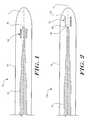
- FIG. 1is a cross-sectional view of an embodiment of an elongate guidewire having a marker member encapsulated within an outer sheath;
- FIG. 2is a cross-sectional view of another embodiment of an elongate guidewire having a marker member encapsulated within an outer sheath;
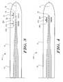
- FIG. 3is a cross-sectional view of another embodiment of an elongate guidewire having multiple marker members encapsulated within an outer sheath;
- FIG. 4is a cross-sectional view of another embodiment of an elongate guidewire having a marker member encapsulated within an outer sheath;
- FIG. 5is a cross-sectional view of a first sheath layer disposed over an elongate shaft
- FIG. 6is a cross-sectional view of a marker member disposed over the first sheath layer shown in FIG. 5 ;
- FIG. 7is a cross-sectional view of second sheath layer disposed over the marker member, first sheath layer, and shaft shown in FIG. 6 ;
- FIG. 8is a cross-sectional view of another embodiment of an elongate guidewire having multiple marker members encapsulated within an outer sheath.
- the inventionin at least some embodiments, includes a guidewire having one or more marker members embedded within an outer sheath. Other embodiments relate to methods of making such guidewires. In at least some embodiments, the embedding of the marker member within the sheath is the sole attachment mechanism for attaching the marker to the guidewire.
- embedding a marker member within the sheathallows the guidewire to have a smooth, lubricious exterior surface and the lubricous exterior surface can allow the guidewire to slide more freely within, for example, a catheter lumen.
- Other desirable properties of some embodimentsmay include, but are not limited to, elimination of the need of an adhesive, solder, or braze to attach the marker member to a central shaft; the ability to extend the marker member distally beyond a distal end of the shaft; and the ability to alter the radiopacity and stiffness/flexibility characteristics of the guidewire.
- FIG. 1is a cross-sectional view of an example embodiment of an elongate guidewire 10 having a marker member 12 disposed around the longitudinal axis L of an elongate shaft 14 and encapsulated within an outer sheath 16 .
- FIGS. 1–7depict guidewire 10 (and analogous guidewires) as an intravascular guidewire.
- guidewire 10could also be another type of guidewire, for example, an endoscopic device, an arthroscopic device, and the like.
- Shaft 14includes a proximal end (not shown), a distal end 18 , and can be made of any material suitable including metals, metal alloys, polymers, or the like, or combinations or mixtures thereof.
- suitable metals and metal alloysinclude stainless steel, such as 304 v stainless steel; nickel-titanium alloy, such as nitinol, nickel-chromium alloy, nickel-chromium-iron alloy, cobalt alloy, or the like; or other suitable material.
- Niitinolwas coined by a group of researchers at the United States Naval Ordinance Laboratory (NOL) who were the first to observe the shape memory behavior of this material.
- the word nitinolis an acronym including the chemical symbol for nickel (Ni), the chemical symbol for titanium (Ti), and an acronym identifying the Naval Ordinance Laboratory (NOL).
- the entire shaft 14can be made of the same material, or in some embodiments, can include portions or sections made of different materials.
- the material used to construct shaft 14is chosen to impart varying flexibility and stiffness characteristics to different portions of shaft 14 .
- a proximal portion and a distal portion of shaft 14may be formed of different materials (i.e., materials having different moduli of elasticity) resulting in a difference in flexibility.
- the material used to construct the proximal portioncan be relatively stiff for pushability and torqueability, and the material used to construct the distal portion can be relatively flexible by comparison for better lateral trackability and steerability.
- the proximal portioncan be formed of straightened 304v stainless steel wire
- the distal portioncan be formed of a straightened super elastic or linear elastic alloy (e.g., nickel-titanium) wire.
- the different portionsare connected using any suitable connecting techniques.
- the different portions of the core wirecan be connected using welding, soldering, brazing, adhesive, or the like, or combinations thereof.
- some embodimentscan include one or more mechanical connectors or connector assemblies to connect the different portions of the core wire that are made of different materials.
- the connectormay comprise any structure generally suitable for connecting portions of a guidewire.
- a suitable structureincludes a structure such as a hypotube or a coiled wire which has an inside diameter sized appropriately to receive and connect to the ends of the proximal portion and the distal portion.
- Other examples of suitable techniques and structures that can be used to interconnect different shaft sectionsare disclosed in U.S. patent application Ser. No. 09/972,276, which is incorporated herein by reference.
- Shaft 14can have a solid cross-section as shown, but in some embodiments, can have a hollow cross-section. In yet other embodiments, shaft 14 can include a combination of areas having solid cross-sections and hollow cross sections. Shaft 14 can be continuously tapered, can have a tapered section or a number or series of tapered sections of differing diameters, or can have a constant diameter. In some embodiments, shaft 14 is tapered or otherwise formed to have a geometry that decreases in cross sectional area toward distal end 18 . If tapered, shaft 14 can include a uniform or a non-uniform transition of the sections, depending on the transition characteristics desired.
- shaft 14may be linearly tapered, tapered in a curvilinear fashion, or tapered in a step-wise fashion.
- the angle of any such taperscan vary, depending upon the desired flexibility characteristics.
- the length of the tapermay be selected to obtain a more (longer length) or less (shorter length) gradual transition in stiffness.
- Shaft 14may be tapered or shaped by any one of a number of different techniques, for example, by centerless grinding methods.
- the centerless grinding techniquemay utilize an indexing system employing sensors (e.g., opticaVreflective, magnetic) to avoid excessive grinding of the connection.
- the centerless grinding techniquemay utilize a CBN or diamond abrasive grinding wheel that is well shaped and dressed to avoid grabbing shaft 14 during the grinding process.
- shaft 14is centerless ground using a Royal Master HI-AC centerless grinder.
- shaft 14(or the length of individual portions thereof) are typically dictated by the length and flexibility characteristics desired in the final guidewire.
- shaft 14may include a proximal portion having a length in the range of about 20 to about 300 centimeters and a distal portion having a length in the range of about 3 to about 50 centimeters. It can be appreciated that alterations in the length of shaft 14 or portions thereof can be altered without departing from the spirit of the invention.
- Marker member 12is disposed around longitudinal axis L of shaft 14 .
- Longitudinal axis L of shaft 14is understood to be an axis running along the length of shaft 14 .
- Longitudinal axis L of shaft 14is understood to extend beyond distal end 18 and the proximal end of shaft 14 , following the same general path or direction as shaft 14 .
- the location of marker member 12can be described relative to longitudinal axis L of shaft 14 .
- describing marker member 12 as being disposed around longitudinal axis L of shaft 14can include marker member 12 being disposed around shaft 14 .
- being disposed around longitudinal axis L of shaft 14can also include marker member 12 being disposed at a location distal to distal end 18 of shaft 14 .
- marker member 12includes radiopaque materials.
- Radiopaque materialsare understood to be materials capable of producing a relatively bright image on a fluoroscopy screen or another imaging technique during a medical procedure. This relatively bright image aids the user of guidewire 10 in determining its location.
- Radiopaque materialscan include, but are not limited to, gold, platinum, palladium, tantalum, tungsten alloy, plastic material loaded with a radiopaque filler, and the like.
- marker member 12can include any shape or form suitable for encapsulation within sheath 16 .
- marker member 12may comprise a tubular, partially tubular, cylindrical (i.e., “C” or “U” shaped), a straight or cupped structure, or other suitably shaped member that is disposed adjacent longitudinal axis L of shaft 14 .
- the marker member 12can have a generally constant diameter configuration, or in some embodiments can be tapered, for example, to correspond with a taper of the core. Such a tapered marker can also provide variable radiopacity in some embodiments. Because marker member 12 is embedded within outer sheath 16 , it can be seen that marker member 12 is spaced from shaft 14 .
- marker member 12may comprise a generally tubular shaped structure, such as a marker band.
- marker member 12need not be directly attached to shaft 14 . In some embodiments, this may be desirable because a solder or adhesive joint (or other suitable connection) between shaft 14 and marker member 12 may create a relatively rigid or inflexible zone within guidewire 10 . Moreover, because it is often desirable to place markers (e.g., marker member 12 ) near the distal end of guidewire 10 , and because it is often desirable for the distal end of such guidewires to be highly flexible, eliminating the need for a solder joint may allow for greater distal flexibility.
- FIGS. 2–8illustrate alterative example embodiments of guidewire 10 , where the location, number, and type of marker member 12 is altered. These alternative embodiments are discussed in more detail below.
- marker member 12may be embedded within sheath 16 .
- embeddedit is meant that marker member 12 is completely encapsulated, surrounded, or covered on all sides by sheath 16 .
- Sheath 16may be made of, for example, a polymer such as a thermoplastic or thermosetting polymer.
- sheath 16may be made of polyurethane, polyether-ester (for example a polyether-ester elastomer such as ARNITEL® available from DSM Engineering Plastics), polyester (for example a polyester elastomer such as HYTREL® available from DuPont), or linear low-density polyethylene (for example REXELL®), and the like, or copolymers or mixtures or combinations thereof.
- polyether-esterfor example a polyether-ester elastomer such as ARNITEL® available from DSM Engineering Plastics
- polyesterfor example a polyester elastomer such as HYTREL® available from DuPont
- linear low-density polyethylenefor example REXELL®
- sheath 16may be made of polymers such as polyamide (for example, DURETHAN® available from Bayer or CRISTAMID® available from Elf Atochem), elastomeric polyamides, block polyamide/ethers, polyether block amide (PEBA, for example available under the trade name PEBAX®), silicones, polyethylene, Marlex high-density polyethylene, and the like, or mixtures, combinations, or copolymers thereof, or with any of the other materials listed above.
- Polyamidesfor example, are particularly suitable for providing a relatively rigid sheath 16 .
- Some other suitable materials for a rigid tubular memberinclude polyetheretherketone (PEEK), polyimide (PI), and polyetherimide (PEI).
- PEBAin contrast to the rigid polyamides, is a relatively flexible polymeric material.
- the use of a polyamidecan impart a slightly less rigid durometer than the rigid polyamides and slightly greater than the flexible PEBA material.
- sheath 16may be a single polymer, multiple layers, or a blend of polymers.
- sheath 16can include a liquid crystal polymer (LCP) blended with other polymers to enhance torqueability.
- LCPliquid crystal polymer
- thermoplastic, solvent soluble, and thermosetting variants of these and other materialscan be employed to achieve the desired results.
- the sheathcan be relatively clear material while in other embodiments the sheath can be more opaque or colored, depending upon the desired visual characteristics.
- a coatingfor example a lubricious (e.g., hydrophylic) or other type of coating may be applied over portions or all of sheath 16 , and/or other portions of guidewire 10 .
- Hydrophobic coatingssuch as fluoropolymers provide a dry lubricity which improves guidewire handling and device exchanges.
- Lubricious coatingsimprove steerability and improve lesion crossing capability.
- Suitable lubricious polymersare well known in the art and may include hydrophilic polymers such as polyarylene oxides, polyvinylpyrolidones, polyvinylalcohols, hydroxy alkyl cellulosics, algins, saccharides, caprolactones, and the like, and mixtures and combinations thereof.
- Hydrophilic polymersmay be blended among themselves or with formulated amounts of water insoluble compounds (including some polymers) to yield coatings with suitable lubricity, bonding, and solubility. Some other examples of such coatings and materials and methods used to create such coatings can be found in U.S. Pat. Nos. 6,139,510 and 5,772,609, which are incorporated herein by reference.
- the more distal portion of guidewire 10is coated with a hydrophilic polymer as discussed above, and the more proximal portion is coated with a fluoropolymer, such as polytetrafluroethylene (PTFE).
- PTFEpolytetrafluroethylene
- FIG. 2is a cross-sectional view of an alternative embodiment of a guidewire 110 .
- Guidewire 110is similar in structure to guidewire 10 shown in FIG. 1 , except that the position of marker member 12 has been altered relative to shaft 14 .
- marker member 12includes a proximal end 22 and a distal end 24 and proximal end 22 is positioned distally of distal end 18 of shaft 14 .
- Altering the position of marker member 12 relative to shaft 14may incorporate desirable properties into guidewire 110 . For example, it may be desirable to distally truncate shaft 14 in order to give guidewire 110 a more flexible distal tip. Because marker member 12 can be positioned beyond distal end 18 of shaft 14 , the distal tip can still easily be imaged (beyond distal end 18 of shaft 14 ) by monitoring the location of marker member 12 .
- marker member 12is positioned near distal end 18 of shaft 14 .
- marker member 12could be positioned at essentially any position along the length of guidewire 110 .
- FIG. 3is a cross-sectional view of a guidewire 210 , which is similar in structure to the guidewire 10 shown in FIG. 1 , but illustrates some other positions of marker member 12 along longitudinal axis L of shaft 14 .
- marker member 12may be positioned such that proximal end 22 is located proximally of distal end 18 of shaft 14 , and distal end 24 is located distally of distal end 18 of shaft 14 .
- guidewire 210can also include one or more additional marker members 212 . Marker member 212 could also be positioned at essentially any position along the length of guidewire 110 .
- marker member 212may be positioned so that proximal end 222 and distal end 224 are located proximally of distal end 18 of shaft 14 .
- marker member 212could be positioned distally of shaft 14 (as shown in FIG. 2 ), partially overlapping with distal end 18 of shaft 14 (similar to marker member 12 of FIG. 3 ).
- FIG. 4is a cross-sectional view of a guidewire 310 .
- Guidewire 310is similar in structure to guidewire 10 as shown in FIG. 1 , except that the marker member 312 having proximal end 322 and distal end 324 is a coil, for example a tubular coil.
- coil 312includes radiopaque material, and may be completely made of, partially made of, or plated with a radiopaque material.
- marker member 312may be used to aid a user in monitoring the position of guidewire 310 , for example, within the human body.
- Coil 312may be arranged or configured in essentially any suitable matter. For example, the number of coils, pitch between windings of the coil, thickness of coil wire, shape of coil wire, and other structural parameters can be altered without departing from the spirit of the invention. Moreover, marker member 312 may be positioned essentially anywhere along longitudinal axis L of shaft 14 , including locations distal of distal end 18 of shaft 14 similar to marker member 12 in FIG. 2 . Thus, marker member 312 may be positioned similar to marker member 12 in FIG. 1 , 2 , or 3 , for example, or at any other suitable location.
- Encapsulation of coil marker member 312can provide additional advantages.
- the encapsulation of coil 312can reduce or eliminate coil bunching or override, which can cause damage to the coil or wire, or can cause wire lockup, for example, within a catheter.
- the coil geometry and configurationcan be varied to provide for variable flexibility and radiopacity characteristics.
- the diameter of the coil, the pitch of the coil, the thickness of the wire and other like structural aspects of the coilcan be varied along the length to provide for variable characteristics.
- FIGS. 5–7illustrate an embodiment of a method of manufacturing guidewire 10 (or any of the guidewires described herein).
- FIG. 5is a cross-sectional view of a first sheath layer 16 a disposed over shaft 14 which has been ground to provide a tapered shape.
- sheath layer 16 ais a portion of outer sheath 16 that is disposed over shaft 14 .
- Layer 16 amay be disposed over shaft 14 using any one of a number of manufacturing techniques. For example, layer 16 a may be disposed over shaft 14 by extrusion, molding, casting, thermal forming, thermal-reforming (such as infrared heat flow or reflow techniques), and other suitable techniques.
- layer 16 amay be ground, worked, or finished to give it an appropriate size, diameter, and/or texture.
- layer 16 amay be useful for layer 16 a to have a generally smooth exterior surface to allow other objects (e.g., marker member 12 ) to be tightly attached thereto.
- itmay be beneficial to have some degree of “roughness” or unevenness to layer 16 a . In some embodiments, this may aid in maintaining the marker positions during processing, or may aid in the blending of layer 16 a with other layers.
- Marker member 12may be disposed over layer 16 a in another manufacturing step as illustrated in FIG. 6 . Again, it can be appreciated that marker member 12 can be disposed at essentially any location along layer 16 a as discussed above. Moreover, additional marker members 12 can be disposed along layer 16 a and marker member 12 can comprise a band, coil, or other suitable structure as described above.
- Suitable attachment techniquesfor example adhesives, thermal bonding, laser bonding, crimping, and the like.
- thermal bondingmay be advantageous because it may eliminate any need to include adhesives or other attachment mechanisms that could impact the flexibility of guidewire 10 .
- adhesivesfor example, ultraviolet adhesives, thixon, and the like
- mechanical attachment, or other attachment techniquescould be used.
- suitable adhesivesinclude materials similar to or compatible with the material of layer 16 a . Additional processing or manufacturing steps may then take place wherein the marker member 12 and/or layer 16 a are ground, worked, or finished.
- a second sheath layer 16 bcan then be disposed over first layer 16 a and marker member 12 , as shown in FIG. 7 .
- Second layer 16 bmay be disposed over layer 16 a and marker member 12 using a suitable technique, for example by extruding, molding, casting, thermal forming, thermal-reforming (e.g., I/R heat flow or reflow), or any other suitable method.
- the second layer 16 bcan be worked, ground, finished, and the like to give guidewire 10 the desired exterior texture and/or shape. Because layer 16 b may comprise the outermost layer of guidewire 10 , it may be desirable in some embodiments to provide the exterior of layer 16 b with a smooth surface. However, alternative textures may be appropriate in other embodiments.
- manufacturing guidewire 10may also include the blending of layer 16 b with layer 16 a .
- Thismay include thermal processing of guidewire 10 that can result in partial melting or another suitable physical change of layers 16 a / 16 b so that the layers flow together or join to form a seamless single layer (i.e., outer sheath 16 ).
- the boundary between layers 16 a / 16 bwould essentially be eliminated and only a single structure, sheath 16 , would remain.
- the blending of layers 16 a and 16 bcould be described in any one of a number of different ways.
- the step of blending layer 16 a with layer 16 bmay be described as melting together, coupling, reflowing the layers, encapsulating, embedding, and the like.
- blending of layers 16 a / 16 bcan occur without adding an additional step.
- manufacturingmay take place at a relatively rapid rate so that layer 16 a is still partially molten or warm when layer 16 b is disposed over layer 16 a and marker member 12 , such that the two layers blend together without additional manufacturing steps. None-the-less, the result of the blending of layers 16 a / 16 b is the formation of sheath 16 as shown in FIG. 1–4 and 7 .
- a pocket or voidcan be maintained about the site of the marker member.
- Some such embodimentscan improve flexibility of the structure. For example, if the maker is a coil, the coil can flex feely within the pocket.
- layers 16 a and 16 bmay be made of the same material (e.g., polyurethane). This may allow the blending of layers 16 a / 16 b to result in a truly seamless joining to form sheath 16 .
- layers 16 a / 16 bmay be made of different, but compatible, materials that also could be essentially seamlessly joined.
- the layers 16 a / 16 bare not necessarily blending together to form a seamless joint, but rather are maintained in position relative to one another using suitable bonding techniques, for example, adhesives, mechanical bonding, and the like.
- guidewire 10may include additional structure or manufacturing steps.
- guidewire 10may include a support structure disposed under, within, or around sheath 16 .
- the support membermay comprise a coil, braid, additional polymeric layer, or other structure, and may extend along a portion or the complete length of guidewire 10 .
- FIG. 8is a cross-sectional view of a guidewire 410 , which is similar to guidewire 10 as shown in FIG. 1 , but illustrates three sets of marker members 412 a/b/c (shown as coils), and that the sheath 16 may cover only a portion of shaft 14 .
- marker members 412 a/b/cshown as coils
- sheath 16may cover only a portion of shaft 14 .
- guidewire 410has the general structure set fourth in FIG. 8 and may be manufactured according to any of the methods described above.
- Shaft 14may also include a first constant diameter portion 26 , a second constant diameter portion 28 , and a third constant diameter portion 30 . Between portion 26 and portion 28 can be a first tapered portion 32 , and between portion 28 and portion 30 can be a second tapered portion 34 .
- the lengths of portions 26 / 28 / 30may be in the range of about 20 to 150 inches for portion 26 , for example, about 37.5 inches; about 1 to 5 inches for portion 28 , for example, about 2.5 inches; and about 0.5 to 2.5 inches for portion 30 , for example, about 1 inch.
- the portions 26 / 28 / 30may also have outside diameters in the range of about 0.01 to about 0.02, for example about 0.013 inches, for portion 26 ; about 0.002 to about 0.006, for example about 0.0044 inches, for portion 28 ; and about 0.001 to about 0.004, for example about 0.003 inches, for portion 30 .
- Tapered portions 32 / 34may taper at a constant angle, a varying angle, a curvilinear fashion, a stepwise fashion, or in any other suitable manner.
- First tapered portion 32may be in the range of about 0.1 to about 0.5 inches in length, for example about 0.3 inches
- second tapered portion 34may be in the range of about 0.5 to about 3 inches in length, for example about 1 inch.
- marker members 412 a/b/ccan be disposed around second portion 28 (i.e., over first layer 16 a ). It can be appreciated, however, that marker 110 members 412 could be disposed at essentially any position along longitudinal axis L of shaft 14 as described above.
- marker member 412 amay be disposed about 2 to 5 inches, for example about 3.9 inches, from distal end 18 of shaft 14 .
- marker member 412 bmay be disposed about 1.5 to 4.5 inches, for example about 3.2 inches, from distal end 18 of shaft 14
- marker member 412 cmay be disposed about 1 to 4 inches, for example about 2.5 inches, from distal end 18 of shaft 14 .
- the spacing between any two marker membersmay be in the range of about 0.5 to 1.5 inches, for example about 0.7 inches.
- manufacturing guidewire 410may include disposing first layer 16 a over shaft 14 as shown in FIG. 5 .
- the outside diameter of layer 16 amay be in the range of about 0.004 to about 0.010 inches, for example about 0.0062 inches.
- the outside diameter of second layer 16 b (and, therefore, sheath 16 )may be in the range of about 0.01 to about 0.02, for example about 0.013 inches.
- sheath 16covers first taper 32 , second portion 28 , second taper 34 , and third portion 30 of shaft 14 .
- a proximal end 36 of sheath 16may extend up to first portion 26 of shaft 14 . This will provide a generally constant outside diameter for guidewire 410 from portion 26 to sheath 16 .
- sheath 16can have an outside diameter that is about equal to the outside diameter of portion 26 .
Landscapes
- Health & Medical Sciences (AREA)
- Life Sciences & Earth Sciences (AREA)
- Biophysics (AREA)
- Pulmonology (AREA)
- Engineering & Computer Science (AREA)
- Anesthesiology (AREA)
- Biomedical Technology (AREA)
- Heart & Thoracic Surgery (AREA)
- Hematology (AREA)
- Animal Behavior & Ethology (AREA)
- General Health & Medical Sciences (AREA)
- Public Health (AREA)
- Veterinary Medicine (AREA)
- Media Introduction/Drainage Providing Device (AREA)
- Insulated Conductors (AREA)
- Road Signs Or Road Markings (AREA)
Abstract
Description
Claims (1)
Priority Applications (8)
| Application Number | Priority Date | Filing Date | Title |
|---|---|---|---|
| US10/152,435US7022086B2 (en) | 2002-05-21 | 2002-05-21 | Guidewire with encapsulated marker |
| PCT/US2003/013393WO2003099371A1 (en) | 2002-05-21 | 2003-04-30 | Guidewire with encapsulated marker |
| AT03736513TATE465770T1 (en) | 2002-05-21 | 2003-04-30 | GUIDE WIRE WITH ENCAPSULED MARKER |
| AU2003237133AAU2003237133A1 (en) | 2002-05-21 | 2003-04-30 | Guidewire with encapsulated marker |
| CA2486176ACA2486176C (en) | 2002-05-21 | 2003-04-30 | Guidewire with encapsulated marker |
| DE60332342TDE60332342D1 (en) | 2002-05-21 | 2003-04-30 | GUIDING WIRE WITH CAPSULE MARKING |
| EP03736513AEP1509274B1 (en) | 2002-05-21 | 2003-04-30 | Guidewire with encapsulated marker |
| JP2004506894AJP4384029B2 (en) | 2002-05-21 | 2003-04-30 | Method for manufacturing a guide wire with an enclosed marker |
Applications Claiming Priority (1)
| Application Number | Priority Date | Filing Date | Title |
|---|---|---|---|
| US10/152,435US7022086B2 (en) | 2002-05-21 | 2002-05-21 | Guidewire with encapsulated marker |
Publications (2)
| Publication Number | Publication Date |
|---|---|
| US20040225231A1 US20040225231A1 (en) | 2004-11-11 |
| US7022086B2true US7022086B2 (en) | 2006-04-04 |
Family
ID=29582063
Family Applications (1)
| Application Number | Title | Priority Date | Filing Date |
|---|---|---|---|
| US10/152,435Expired - Fee RelatedUS7022086B2 (en) | 2002-05-21 | 2002-05-21 | Guidewire with encapsulated marker |
Country Status (8)
| Country | Link |
|---|---|
| US (1) | US7022086B2 (en) |
| EP (1) | EP1509274B1 (en) |
| JP (1) | JP4384029B2 (en) |
| AT (1) | ATE465770T1 (en) |
| AU (1) | AU2003237133A1 (en) |
| CA (1) | CA2486176C (en) |
| DE (1) | DE60332342D1 (en) |
| WO (1) | WO2003099371A1 (en) |
Cited By (7)
| Publication number | Priority date | Publication date | Assignee | Title |
|---|---|---|---|---|
| US20090162530A1 (en)* | 2007-12-21 | 2009-06-25 | Orion Industries, Ltd. | Marked precoated medical device and method of manufacturing same |
| US20090181156A1 (en)* | 2007-12-21 | 2009-07-16 | Bruce Nesbitt | Marked precoated medical device and method of manufacturing same |
| US20090182246A1 (en)* | 2007-12-28 | 2009-07-16 | Terumo Kabushiki Kaisha | Guide wire |
| US20090211909A1 (en)* | 2007-12-21 | 2009-08-27 | Bruce Nesbitt | Marked precoated medical device and method of manufacturing same |
| US7714217B2 (en) | 2007-12-21 | 2010-05-11 | Innovatech, Llc | Marked precoated strings and method of manufacturing same |
| US8231926B2 (en) | 2007-12-21 | 2012-07-31 | Innovatech, Llc | Marked precoated medical device and method of manufacturing same |
| US8900652B1 (en) | 2011-03-14 | 2014-12-02 | Innovatech, Llc | Marked fluoropolymer surfaces and method of manufacturing same |
Families Citing this family (16)
| Publication number | Priority date | Publication date | Assignee | Title |
|---|---|---|---|---|
| US20050246007A1 (en)* | 2004-04-28 | 2005-11-03 | Medtronic, Inc. | Novel lead body assemblies |
| DE102004028367A1 (en)* | 2004-06-11 | 2005-12-29 | Biotronik Vi Patent Ag | Catheter Guidewire especially for cardio-vascular procedures |
| JP2006068497A (en)* | 2004-08-03 | 2006-03-16 | Ist:Kk | Method for manufacturing medical wire and medical wire |
| JP2006320638A (en)* | 2005-05-20 | 2006-11-30 | Ist Corp | Manufacturing method of medical wire |
| US20070179582A1 (en)* | 2006-01-31 | 2007-08-02 | Marshall Mark T | Polymer reinforced coil conductor for torque transmission |
| US8622931B2 (en) | 2007-02-09 | 2014-01-07 | Boston Scientific Scimed, Inc. | Extruded guidewires and methods of making |
| AU2008274922B2 (en)* | 2007-07-11 | 2014-04-03 | Board Of Regents, The University Of Texas System | Seeds and markers for use in imaging |
| DE102008006402A1 (en) | 2008-01-28 | 2009-07-30 | Magnamedics Gmbh | Coated instruments for invasive medicine |
| US11298251B2 (en) | 2010-11-17 | 2022-04-12 | Abbott Cardiovascular Systems, Inc. | Radiopaque intraluminal stents comprising cobalt-based alloys with primarily single-phase supersaturated tungsten content |
| EP2665493B1 (en) | 2011-01-20 | 2018-03-21 | Board Of Regents, The University Of Texas System | Mri markers, delivery and extraction systems, and methods of manufacture and use thereof |
| JP5382953B2 (en)* | 2011-01-28 | 2014-01-08 | 朝日インテック株式会社 | Guide wire |
| US9724494B2 (en) | 2011-06-29 | 2017-08-08 | Abbott Cardiovascular Systems, Inc. | Guide wire device including a solderable linear elastic nickel-titanium distal end section and methods of preparation therefor |
| CA2916984A1 (en)* | 2013-07-03 | 2015-01-08 | Boston Scientifc Scimed, Inc. | Variable diameter guidewire |
| JP2019129957A (en)* | 2018-01-30 | 2019-08-08 | オリンパス株式会社 | Resin molded product for medical instrument and medical instrument |
| US12151049B2 (en) | 2019-10-14 | 2024-11-26 | Abbott Cardiovascular Systems, Inc. | Methods for manufacturing radiopaque intraluminal stents comprising cobalt-based alloys with supersaturated tungsten content |
| WO2025175159A2 (en)* | 2024-02-16 | 2025-08-21 | Muffin Incorporated | Mri compatible interventional medical devices, and methods of manufacture and use |
Citations (49)
| Publication number | Priority date | Publication date | Assignee | Title |
|---|---|---|---|---|
| US4571240A (en) | 1983-08-12 | 1986-02-18 | Advanced Cardiovascular Systems, Inc. | Catheter having encapsulated tip marker |
| US4657024A (en) | 1980-02-04 | 1987-04-14 | Teleflex Incorporated | Medical-surgical catheter |
| US4763647A (en) | 1987-01-06 | 1988-08-16 | C. R. Bard, Inc. | Dual coil steerable guidewire |
| US4922924A (en) | 1989-04-27 | 1990-05-08 | C. R. Bard, Inc. | Catheter guidewire with varying radiopacity |
| WO1991000051A1 (en) | 1989-06-28 | 1991-01-10 | Boston Scientific Corporation | Steerable highly elongated guidewire |
| EP0407965A1 (en) | 1989-07-10 | 1991-01-16 | Terumo Kabushiki Kaisha | Guide wire |
| US5063935A (en) | 1989-04-27 | 1991-11-12 | C. R. Bard, Inc. | Catheter guidewire with varying radiopacity |
| US5144959A (en) | 1989-08-15 | 1992-09-08 | C. R. Bard, Inc. | Catheter guidewire with varying radiopacity |
| US5174302A (en) | 1990-12-04 | 1992-12-29 | Cordis Corporation | Variable radiopacity guidewire with spaced highly radiopaque regions |
| US5213111A (en) | 1991-07-10 | 1993-05-25 | Cook Incorporated | Composite wire guide construction |
| US5228453A (en) | 1991-05-07 | 1993-07-20 | Target Therapeutics, Inc. | Catheter guide wire |
| US5241970A (en) | 1991-05-17 | 1993-09-07 | Wilson-Cook Medical, Inc. | Papillotome/sphincterotome procedures and a wire guide specially |
| US5253653A (en) | 1991-10-31 | 1993-10-19 | Boston Scientific Corp. | Fluoroscopically viewable guidewire for catheters |
| US5333620A (en) | 1991-10-30 | 1994-08-02 | C. R. Bard, Inc. | High performance plastic coated medical guidewire |
| US5345945A (en) | 1990-08-29 | 1994-09-13 | Baxter International Inc. | Dual coil guidewire with radiopaque distal tip |
| US5353808A (en) | 1992-03-04 | 1994-10-11 | Cordis Corporation | Guidewire having distally located marker segment |
| US5368048A (en) | 1993-04-19 | 1994-11-29 | Stoy; George P. | Method of making radio-opaque tipped, sleeved guidewire and product |
| US5409015A (en) | 1993-05-11 | 1995-04-25 | Target Therapeutics, Inc. | Deformable tip super elastic guidewire |
| US5443907A (en) | 1991-06-18 | 1995-08-22 | Scimed Life Systems, Inc. | Coating for medical insertion guides |
| US5452726A (en) | 1991-06-18 | 1995-09-26 | Scimed Life Systems, Inc. | Intravascular guide wire and method for manufacture thereof |
| JPH07275367A (en)* | 1994-04-07 | 1995-10-24 | Kato Hatsujo Kaisha Ltd | Guide wire and production thereof |
| US5562127A (en)* | 1993-08-06 | 1996-10-08 | Minnesota Mining And Manufacturing Company | Flexible, chlorine free multilayered tubing |
| US5606981A (en) | 1994-03-11 | 1997-03-04 | C. R. Bard, Inc. | Catheter guidewire with radiopaque markers |
| JPH0994298A (en) | 1995-09-28 | 1997-04-08 | Terumo Corp | Guide wire |
| US5772609A (en) | 1993-05-11 | 1998-06-30 | Target Therapeutics, Inc. | Guidewire with variable flexibility due to polymeric coatings |
| US5797857A (en) | 1993-12-24 | 1998-08-25 | Terumo Kabushiki Kaisha | Guide wire |
| US5817017A (en) | 1994-04-12 | 1998-10-06 | Pharmacyclics, Inc. | Medical devices and materials having enhanced magnetic images visibility |
| EP0868925A2 (en) | 1997-03-31 | 1998-10-07 | Terumo Kabushiki Kaisha | Guide wire |
| US5833631A (en) | 1996-06-28 | 1998-11-10 | Target Therapeutics, Inc. | Fiber tip guidewire |
| US5836893A (en) | 1996-03-08 | 1998-11-17 | Scimed Life Systems, Inc. | Intravascular guidewire |
| US5836892A (en) | 1995-10-30 | 1998-11-17 | Cordis Corporation | Guidewire with radiopaque markers |
| US5876356A (en) | 1997-04-02 | 1999-03-02 | Cordis Corporation | Superelastic guidewire with a shapeable tip |
| US5916178A (en) | 1995-03-30 | 1999-06-29 | Medtronic, Inc. | Steerable high support guidewire with thin wall nitinol tube |
| US5954672A (en) | 1997-05-21 | 1999-09-21 | Schneider (Europe) Gmbh | Controlled gap guidewire |
| US5993424A (en) | 1996-08-05 | 1999-11-30 | Cordis Corporation | Guidewire having a distal tip that can change its shape within a vessel |
| US5997487A (en) | 1995-10-11 | 1999-12-07 | Micro Therapeutics, Inc. | Infusion wire having fixed core wire |
| US6027461A (en) | 1995-10-11 | 2000-02-22 | Micro Therapeutics, Inc. | Infusion guidewire having fixed core wire and flexible radiopaque marker |
| US6139510A (en) | 1994-05-11 | 2000-10-31 | Target Therapeutics Inc. | Super elastic alloy guidewire |
| US6171295B1 (en) | 1999-01-20 | 2001-01-09 | Scimed Life Systems, Inc. | Intravascular catheter with composite reinforcement |
| US6183420B1 (en) | 1997-06-20 | 2001-02-06 | Medtronic Ave, Inc. | Variable stiffness angioplasty guide wire |
| US6251086B1 (en) | 1999-07-27 | 2001-06-26 | Scimed Life Systems, Inc. | Guide wire with hydrophilically coated tip |
| US6306105B1 (en) | 1998-05-14 | 2001-10-23 | Scimed Life Systems, Inc. | High performance coil wire |
| WO2001095794A1 (en) | 2000-06-12 | 2001-12-20 | Cordis Corporation | Vascular guidewire for magnetic resonance and/or fluoroscopy |
| US20020042582A1 (en) | 2000-10-05 | 2002-04-11 | Scimed Life Systems, Inc. | Guidewire having a marker segment for length assessment |
| US6494847B1 (en)* | 1998-12-30 | 2002-12-17 | Advanced Cardiovascular Systems, Inc. | Guide wire with multiple polymer jackets over distal and intermediate core sections |
| US20030069521A1 (en)* | 2001-10-05 | 2003-04-10 | Brian Reynolds | Composite guidewire |
| US20030120181A1 (en)* | 2001-11-05 | 2003-06-26 | Memry Corporation | Work-hardened pseudoelastic guide wires |
| US6636758B2 (en)* | 2001-05-01 | 2003-10-21 | Concentric Medical, Inc. | Marker wire and process for using it |
| US6673025B1 (en)* | 1993-12-01 | 2004-01-06 | Advanced Cardiovascular Systems, Inc. | Polymer coated guidewire |
- 2002
- 2002-05-21USUS10/152,435patent/US7022086B2/ennot_activeExpired - Fee Related
- 2003
- 2003-04-30ATAT03736513Tpatent/ATE465770T1/ennot_activeIP Right Cessation
- 2003-04-30DEDE60332342Tpatent/DE60332342D1/ennot_activeExpired - Lifetime
- 2003-04-30CACA2486176Apatent/CA2486176C/ennot_activeExpired - Fee Related
- 2003-04-30AUAU2003237133Apatent/AU2003237133A1/ennot_activeAbandoned
- 2003-04-30WOPCT/US2003/013393patent/WO2003099371A1/enactiveApplication Filing
- 2003-04-30EPEP03736513Apatent/EP1509274B1/ennot_activeExpired - Lifetime
- 2003-04-30JPJP2004506894Apatent/JP4384029B2/ennot_activeExpired - Fee Related
Patent Citations (51)
| Publication number | Priority date | Publication date | Assignee | Title |
|---|---|---|---|---|
| US4657024A (en) | 1980-02-04 | 1987-04-14 | Teleflex Incorporated | Medical-surgical catheter |
| US4571240A (en) | 1983-08-12 | 1986-02-18 | Advanced Cardiovascular Systems, Inc. | Catheter having encapsulated tip marker |
| US4763647A (en) | 1987-01-06 | 1988-08-16 | C. R. Bard, Inc. | Dual coil steerable guidewire |
| US4922924A (en) | 1989-04-27 | 1990-05-08 | C. R. Bard, Inc. | Catheter guidewire with varying radiopacity |
| US5063935A (en) | 1989-04-27 | 1991-11-12 | C. R. Bard, Inc. | Catheter guidewire with varying radiopacity |
| WO1991000051A1 (en) | 1989-06-28 | 1991-01-10 | Boston Scientific Corporation | Steerable highly elongated guidewire |
| EP0407965A1 (en) | 1989-07-10 | 1991-01-16 | Terumo Kabushiki Kaisha | Guide wire |
| US5144959A (en) | 1989-08-15 | 1992-09-08 | C. R. Bard, Inc. | Catheter guidewire with varying radiopacity |
| US5345945A (en) | 1990-08-29 | 1994-09-13 | Baxter International Inc. | Dual coil guidewire with radiopaque distal tip |
| US5174302A (en) | 1990-12-04 | 1992-12-29 | Cordis Corporation | Variable radiopacity guidewire with spaced highly radiopaque regions |
| US5228453A (en) | 1991-05-07 | 1993-07-20 | Target Therapeutics, Inc. | Catheter guide wire |
| US5241970A (en) | 1991-05-17 | 1993-09-07 | Wilson-Cook Medical, Inc. | Papillotome/sphincterotome procedures and a wire guide specially |
| US5452726A (en) | 1991-06-18 | 1995-09-26 | Scimed Life Systems, Inc. | Intravascular guide wire and method for manufacture thereof |
| US5443907A (en) | 1991-06-18 | 1995-08-22 | Scimed Life Systems, Inc. | Coating for medical insertion guides |
| US5213111A (en) | 1991-07-10 | 1993-05-25 | Cook Incorporated | Composite wire guide construction |
| US5333620A (en) | 1991-10-30 | 1994-08-02 | C. R. Bard, Inc. | High performance plastic coated medical guidewire |
| US5253653A (en) | 1991-10-31 | 1993-10-19 | Boston Scientific Corp. | Fluoroscopically viewable guidewire for catheters |
| US5353808A (en) | 1992-03-04 | 1994-10-11 | Cordis Corporation | Guidewire having distally located marker segment |
| US5368048A (en) | 1993-04-19 | 1994-11-29 | Stoy; George P. | Method of making radio-opaque tipped, sleeved guidewire and product |
| US5772609A (en) | 1993-05-11 | 1998-06-30 | Target Therapeutics, Inc. | Guidewire with variable flexibility due to polymeric coatings |
| US5636642A (en) | 1993-05-11 | 1997-06-10 | Target Therapeutics, Inc. | Deformable tip super elastic guidewire |
| US5409015A (en) | 1993-05-11 | 1995-04-25 | Target Therapeutics, Inc. | Deformable tip super elastic guidewire |
| US5562127A (en)* | 1993-08-06 | 1996-10-08 | Minnesota Mining And Manufacturing Company | Flexible, chlorine free multilayered tubing |
| US6673025B1 (en)* | 1993-12-01 | 2004-01-06 | Advanced Cardiovascular Systems, Inc. | Polymer coated guidewire |
| US5797857A (en) | 1993-12-24 | 1998-08-25 | Terumo Kabushiki Kaisha | Guide wire |
| US5606981A (en) | 1994-03-11 | 1997-03-04 | C. R. Bard, Inc. | Catheter guidewire with radiopaque markers |
| JPH07275367A (en)* | 1994-04-07 | 1995-10-24 | Kato Hatsujo Kaisha Ltd | Guide wire and production thereof |
| US5817017A (en) | 1994-04-12 | 1998-10-06 | Pharmacyclics, Inc. | Medical devices and materials having enhanced magnetic images visibility |
| US6139510A (en) | 1994-05-11 | 2000-10-31 | Target Therapeutics Inc. | Super elastic alloy guidewire |
| US5916178A (en) | 1995-03-30 | 1999-06-29 | Medtronic, Inc. | Steerable high support guidewire with thin wall nitinol tube |
| JPH0994298A (en) | 1995-09-28 | 1997-04-08 | Terumo Corp | Guide wire |
| US6027461A (en) | 1995-10-11 | 2000-02-22 | Micro Therapeutics, Inc. | Infusion guidewire having fixed core wire and flexible radiopaque marker |
| US5997487A (en) | 1995-10-11 | 1999-12-07 | Micro Therapeutics, Inc. | Infusion wire having fixed core wire |
| US5836892A (en) | 1995-10-30 | 1998-11-17 | Cordis Corporation | Guidewire with radiopaque markers |
| US5836893A (en) | 1996-03-08 | 1998-11-17 | Scimed Life Systems, Inc. | Intravascular guidewire |
| US5833631A (en) | 1996-06-28 | 1998-11-10 | Target Therapeutics, Inc. | Fiber tip guidewire |
| US5993424A (en) | 1996-08-05 | 1999-11-30 | Cordis Corporation | Guidewire having a distal tip that can change its shape within a vessel |
| EP0868925A2 (en) | 1997-03-31 | 1998-10-07 | Terumo Kabushiki Kaisha | Guide wire |
| US5876356A (en) | 1997-04-02 | 1999-03-02 | Cordis Corporation | Superelastic guidewire with a shapeable tip |
| US5954672A (en) | 1997-05-21 | 1999-09-21 | Schneider (Europe) Gmbh | Controlled gap guidewire |
| US6183420B1 (en) | 1997-06-20 | 2001-02-06 | Medtronic Ave, Inc. | Variable stiffness angioplasty guide wire |
| US6306105B1 (en) | 1998-05-14 | 2001-10-23 | Scimed Life Systems, Inc. | High performance coil wire |
| US6494847B1 (en)* | 1998-12-30 | 2002-12-17 | Advanced Cardiovascular Systems, Inc. | Guide wire with multiple polymer jackets over distal and intermediate core sections |
| US6171295B1 (en) | 1999-01-20 | 2001-01-09 | Scimed Life Systems, Inc. | Intravascular catheter with composite reinforcement |
| US6251086B1 (en) | 1999-07-27 | 2001-06-26 | Scimed Life Systems, Inc. | Guide wire with hydrophilically coated tip |
| WO2001095794A1 (en) | 2000-06-12 | 2001-12-20 | Cordis Corporation | Vascular guidewire for magnetic resonance and/or fluoroscopy |
| US20020042582A1 (en) | 2000-10-05 | 2002-04-11 | Scimed Life Systems, Inc. | Guidewire having a marker segment for length assessment |
| US6620114B2 (en)* | 2000-10-05 | 2003-09-16 | Scimed Life Systems, Inc. | Guidewire having a marker segment for length assessment |
| US6636758B2 (en)* | 2001-05-01 | 2003-10-21 | Concentric Medical, Inc. | Marker wire and process for using it |
| US20030069521A1 (en)* | 2001-10-05 | 2003-04-10 | Brian Reynolds | Composite guidewire |
| US20030120181A1 (en)* | 2001-11-05 | 2003-06-26 | Memry Corporation | Work-hardened pseudoelastic guide wires |
Cited By (22)
| Publication number | Priority date | Publication date | Assignee | Title |
|---|---|---|---|---|
| US8362344B2 (en) | 2007-12-21 | 2013-01-29 | Innovatech, Llc | Marked precoated strings and method of manufacturing same |
| US8574171B2 (en) | 2007-12-21 | 2013-11-05 | Innovatech, Llc | Marked precoated medical device and method of manufacturing same |
| US10573280B2 (en) | 2007-12-21 | 2020-02-25 | Innovatech, Llc | Marked precoated strings and method of manufacturing same |
| US20090211909A1 (en)* | 2007-12-21 | 2009-08-27 | Bruce Nesbitt | Marked precoated medical device and method of manufacturing same |
| US7714217B2 (en) | 2007-12-21 | 2010-05-11 | Innovatech, Llc | Marked precoated strings and method of manufacturing same |
| US20100199830A1 (en)* | 2007-12-21 | 2010-08-12 | Innovatech, Llc | Marked precoated strings and method of manufacturing same |
| US7811623B2 (en) | 2007-12-21 | 2010-10-12 | Innovatech, Llc | Marked precoated medical device and method of manufacturing same |
| US8048471B2 (en) | 2007-12-21 | 2011-11-01 | Innovatech, Llc | Marked precoated medical device and method of manufacturing same |
| US8231926B2 (en) | 2007-12-21 | 2012-07-31 | Innovatech, Llc | Marked precoated medical device and method of manufacturing same |
| US8772614B2 (en) | 2007-12-21 | 2014-07-08 | Innovatech, Llc | Marked precoated strings and method of manufacturing same |
| US20090181156A1 (en)* | 2007-12-21 | 2009-07-16 | Bruce Nesbitt | Marked precoated medical device and method of manufacturing same |
| US20090162530A1 (en)* | 2007-12-21 | 2009-06-25 | Orion Industries, Ltd. | Marked precoated medical device and method of manufacturing same |
| US8231927B2 (en) | 2007-12-21 | 2012-07-31 | Innovatech, Llc | Marked precoated medical device and method of manufacturing same |
| US9782569B2 (en) | 2007-12-21 | 2017-10-10 | Innovatech, Llc | Marked precoated medical device and method of manufacturing same |
| US9355621B2 (en) | 2007-12-21 | 2016-05-31 | Innovatech, Llc | Marked precoated strings and method of manufacturing same |
| US8940357B2 (en) | 2007-12-21 | 2015-01-27 | Innovatech Llc | Marked precoated medical device and method of manufacturing same |
| US8827926B2 (en) | 2007-12-28 | 2014-09-09 | Terumo Kabushiki Kaisha | Guide wire |
| US20090182246A1 (en)* | 2007-12-28 | 2009-07-16 | Terumo Kabushiki Kaisha | Guide wire |
| US8900652B1 (en) | 2011-03-14 | 2014-12-02 | Innovatech, Llc | Marked fluoropolymer surfaces and method of manufacturing same |
| US9744271B2 (en) | 2011-03-14 | 2017-08-29 | Innovatech, Llc | Marked fluoropolymer surfaces and method of manufacturing same |
| US9962470B2 (en) | 2011-03-14 | 2018-05-08 | Innovatech, Llc | Marked fluoropolymer surfaces and method of manufacturing same |
| US10111987B2 (en) | 2011-03-14 | 2018-10-30 | Innovatech, Llc | Marked fluoropolymer surfaces and method of manufacturing same |
Also Published As
| Publication number | Publication date |
|---|---|
| DE60332342D1 (en) | 2010-06-10 |
| JP2005525916A (en) | 2005-09-02 |
| EP1509274A1 (en) | 2005-03-02 |
| US20040225231A1 (en) | 2004-11-11 |
| AU2003237133A1 (en) | 2003-12-12 |
| JP4384029B2 (en) | 2009-12-16 |
| CA2486176C (en) | 2012-02-21 |
| CA2486176A1 (en) | 2003-12-04 |
| WO2003099371A1 (en) | 2003-12-04 |
| ATE465770T1 (en) | 2010-05-15 |
| EP1509274B1 (en) | 2010-04-28 |
Similar Documents
| Publication | Publication Date | Title |
|---|---|---|
| US7022086B2 (en) | Guidewire with encapsulated marker | |
| EP1699516B1 (en) | Medical device with push force limiter | |
| US7914467B2 (en) | Tubular member having tapered transition for use in a medical device | |
| US8419658B2 (en) | Medical device including structure for crossing an occlusion in a vessel | |
| US8337519B2 (en) | Embolic protection filtering device | |
| US9375234B2 (en) | Medical device including structure for crossing an occlusion in a vessel | |
| US8551020B2 (en) | Crossing guidewire | |
| US20040064069A1 (en) | Medical device with support member | |
| US20090292225A1 (en) | Medical device including a braid for crossing an occlusion in a vessel | |
| WO2009058718A1 (en) | Medical device for crossing an occlusion in a vessel | |
| US20040167438A1 (en) | Reinforced medical device | |
| WO2008131296A1 (en) | Medical device | |
| EP2068994A2 (en) | Catheter shaft including a metallic tapered region | |
| EP1558323A1 (en) | Medical device having flexible distal tip |
Legal Events
| Date | Code | Title | Description |
|---|---|---|---|
| AS | Assignment | Owner name:SCIMED LIFE SYSTEMS, INC., MINNESOTA Free format text:ASSIGNMENT OF ASSIGNORS INTEREST;ASSIGNOR:EHR, TIMOTHY G. J.;REEL/FRAME:012925/0741 Effective date:20020514 | |
| CC | Certificate of correction | ||
| AS | Assignment | Owner name:BOSTON SCIENTIFIC SCIMED, INC., MINNESOTA Free format text:CHANGE OF NAME;ASSIGNOR:SCIMED LIFE SYSTEMS, INC.;REEL/FRAME:018505/0868 Effective date:20050101 Owner name:BOSTON SCIENTIFIC SCIMED, INC.,MINNESOTA Free format text:CHANGE OF NAME;ASSIGNOR:SCIMED LIFE SYSTEMS, INC.;REEL/FRAME:018505/0868 Effective date:20050101 | |
| FEPP | Fee payment procedure | Free format text:PAYOR NUMBER ASSIGNED (ORIGINAL EVENT CODE: ASPN); ENTITY STATUS OF PATENT OWNER: LARGE ENTITY Free format text:PAYER NUMBER DE-ASSIGNED (ORIGINAL EVENT CODE: RMPN); ENTITY STATUS OF PATENT OWNER: LARGE ENTITY | |
| FPAY | Fee payment | Year of fee payment:4 | |
| FPAY | Fee payment | Year of fee payment:8 | |
| FEPP | Fee payment procedure | Free format text:MAINTENANCE FEE REMINDER MAILED (ORIGINAL EVENT CODE: REM.) | |
| LAPS | Lapse for failure to pay maintenance fees | Free format text:PATENT EXPIRED FOR FAILURE TO PAY MAINTENANCE FEES (ORIGINAL EVENT CODE: EXP.) | |
| STCH | Information on status: patent discontinuation | Free format text:PATENT EXPIRED DUE TO NONPAYMENT OF MAINTENANCE FEES UNDER 37 CFR 1.362 | |
| FP | Lapsed due to failure to pay maintenance fee | Effective date:20180404 |