US7021790B2 - Miniature LED flashlight with snap-on carrier - Google Patents
Miniature LED flashlight with snap-on carrierDownload PDFInfo
- Publication number
- US7021790B2 US7021790B2US10/624,216US62421603AUS7021790B2US 7021790 B2US7021790 B2US 7021790B2US 62421603 AUS62421603 AUS 62421603AUS 7021790 B2US7021790 B2US 7021790B2
- Authority
- US
- United States
- Prior art keywords
- flashlight
- accordance
- flashlight assembly
- assembly
- carrier
- Prior art date
- Legal status (The legal status is an assumption and is not a legal conclusion. Google has not performed a legal analysis and makes no representation as to the accuracy of the status listed.)
- Expired - Fee Related, expires
Links
- 230000003213activating effectEffects0.000claimsabstractdescription3
- 125000006850spacer groupChemical group0.000claimsdescription14
- 229920003023plasticPolymers0.000claimsdescription7
- 239000013536elastomeric materialSubstances0.000claimsdescription5
- 238000000034methodMethods0.000claimsdescription4
- 239000011888foilSubstances0.000claimsdescription3
- 239000004020conductorSubstances0.000claims4
- 238000012216screeningMethods0.000claims1
- 239000000463materialSubstances0.000description5
- 230000000994depressogenic effectEffects0.000description4
- 238000012986modificationMethods0.000description4
- 230000004048modificationEffects0.000description4
- 230000003993interactionEffects0.000description3
- 230000002093peripheral effectEffects0.000description3
- 230000008569processEffects0.000description3
- WHXSMMKQMYFTQS-UHFFFAOYSA-NLithiumChemical compound[Li]WHXSMMKQMYFTQS-UHFFFAOYSA-N0.000description2
- 239000003086colorantSubstances0.000description2
- 238000003780insertionMethods0.000description2
- 230000037431insertionEffects0.000description2
- 229910052744lithiumInorganic materials0.000description2
- 230000002411adverseEffects0.000description1
- 239000000969carrierSubstances0.000description1
- 238000005530etchingMethods0.000description1
- 229920002457flexible plasticPolymers0.000description1
- 238000004519manufacturing processMethods0.000description1
- 230000013011matingEffects0.000description1
- 230000007246mechanismEffects0.000description1
- 229910052751metalInorganic materials0.000description1
- 239000002184metalSubstances0.000description1
- 238000000465mouldingMethods0.000description1
- 230000008520organizationEffects0.000description1
- 238000003825pressingMethods0.000description1
- 239000012858resilient materialSubstances0.000description1
- 230000000717retained effectEffects0.000description1
Images


Classifications
- F—MECHANICAL ENGINEERING; LIGHTING; HEATING; WEAPONS; BLASTING
- F21—LIGHTING
- F21V—FUNCTIONAL FEATURES OR DETAILS OF LIGHTING DEVICES OR SYSTEMS THEREOF; STRUCTURAL COMBINATIONS OF LIGHTING DEVICES WITH OTHER ARTICLES, NOT OTHERWISE PROVIDED FOR
- F21V23/00—Arrangement of electric circuit elements in or on lighting devices
- F21V23/04—Arrangement of electric circuit elements in or on lighting devices the elements being switches
- F21V23/0414—Arrangement of electric circuit elements in or on lighting devices the elements being switches specially adapted to be used with portable lighting devices
- A—HUMAN NECESSITIES
- A44—HABERDASHERY; JEWELLERY
- A44B—BUTTONS, PINS, BUCKLES, SLIDE FASTENERS, OR THE LIKE
- A44B15/00—Key-rings
- A44B15/005—Fobs
- F—MECHANICAL ENGINEERING; LIGHTING; HEATING; WEAPONS; BLASTING
- F21—LIGHTING
- F21L—LIGHTING DEVICES OR SYSTEMS THEREOF, BEING PORTABLE OR SPECIALLY ADAPTED FOR TRANSPORTATION
- F21L4/00—Electric lighting devices with self-contained electric batteries or cells
- F21L4/02—Electric lighting devices with self-contained electric batteries or cells characterised by the provision of two or more light sources
- F21L4/022—Pocket lamps
- F21L4/027—Pocket lamps the light sources being a LED
- F—MECHANICAL ENGINEERING; LIGHTING; HEATING; WEAPONS; BLASTING
- F21—LIGHTING
- F21V—FUNCTIONAL FEATURES OR DETAILS OF LIGHTING DEVICES OR SYSTEMS THEREOF; STRUCTURAL COMBINATIONS OF LIGHTING DEVICES WITH OTHER ARTICLES, NOT OTHERWISE PROVIDED FOR
- F21V21/00—Supporting, suspending, or attaching arrangements for lighting devices; Hand grips
- F21V21/08—Devices for easy attachment to any desired place, e.g. clip, clamp, magnet
- F21V21/088—Clips; Clamps
- F21V21/0885—Clips; Clamps for portable lighting devices
- F—MECHANICAL ENGINEERING; LIGHTING; HEATING; WEAPONS; BLASTING
- F21—LIGHTING
- F21Y—INDEXING SCHEME ASSOCIATED WITH SUBCLASSES F21K, F21L, F21S and F21V, RELATING TO THE FORM OR THE KIND OF THE LIGHT SOURCES OR OF THE COLOUR OF THE LIGHT EMITTED
- F21Y2115/00—Light-generating elements of semiconductor light sources
- F21Y2115/10—Light-emitting diodes [LED]
Definitions
- the present inventionrelates generally to flashlights, and more particularly to a miniature flashlight having a light emitting diode (LED) light source and an associated case or carrier that is useful for law enforcement personnel and civilians alike.
- LEDlight emitting diode
- Flashlightsare used for a wide variety of purposes. For example, they are often used during traffic stops to illuminate the interior of a stopped vehicle or to complete a police report in the dark. They are also used to facilitate searches of poorly lit areas, and may be used to illuminate dark alleys or stairwells. Law enforcement personnel also use flashlights to check or adjust their equipment when positioned in a darkened area or at night, and may also be used to send signals to one another.
- conventional flashlightsemploy an incandescent light bulb and dry cell batteries enclosed in a housing typically having an elongated cylindrical body section and a head section. Flashlights of this type are often bulky and cumbersome. Law enforcement personnel often wear a holster to carry a flashlight on their person. However, the inconvenient size and weight of conventional flashlights reduce the mobility of law enforcement personnel required to carry such flashlights along with other law enforcement equipment. As a result, the flashlight may purposefully or inadvertently be left, presenting a problem when the need for a flashlight arises and the officer does not have one readily available.
- flashlightsare favored for various security purposes. For example, when going to one's car during darkness, it is not uncommon for an individual, especially a female, to carry a small flashlight to assist in locating the door lock keyhole or to check for potential assailants. Even small conventional flashlights, however, can be cumbersome and inconvenient to carry for this purpose.
- LED flashlightstypically require slide or pressure switches that directly engage LED leads to batteries in order to actuate the light. This results in increased fatigue on the LED leads, and adversely affects switch reliability.
- many small flashlightsare constructed with hard plastic outer shells unsuitable for marking, etching, or interchanging.
- Other small flashlightsmay include an integral clip for attachment to clothes, baggage, or keys, but they generally have spring-biased locking mechanisms, which are vulnerable to breakage and typically require extra parts and expense in manufacturing. Further, most flashlights require at least partial human assembly, which is a relatively labor-intensive process and expensive.
- hat-mounted and “tool-mounted” flashlightsare described in the prior art. Such devices, however, typically use incandescent bulbs and dry cell batteries.
- One such hat-mounted deviceis activated when a user dons the hat.
- Anotheris activated when a user twists a flashlight barrel, or otherwise activates a switch.
- One known tool-mounted flashlightis activated when an insulating tab disposed between switch contacts is removed.
- hat-mounted and tool-mounted flashlightsrequire manual interaction to activate and deactivate the light.
- a miniature flashlight and an associated case adapted to be releasably attached to a supportsuch as a hat brim or other article of clothing, wherein the flashlight may be activated either manually or when selectively inserted into the case, would provide significant advantages over known flashlights and associated cases or carriers.
- One of the objects of the present inventionis to provide a case and a small, compact flashlight that may be activated either manually or when the flashlight is selectively inserted into the case.
- a more particular object of the inventionis to provide a miniature flashlight that includes a momentary contact switch, interchangeable body inserts, and an integral, split-ring clip.
- the case or carrierslideably receives the flashlight and includes a resilient mounting clip that allows attachment to an article of clothing or other support member.
- a feature of the present inventionlies in the provision of a dome plate switch element, preferably located between one of the LED leads and the power source, but out of direct contact with the power source.
- the switchis activated by applying pressure to a switch button, which forces one of the LED leads into contact with the dome plate, which in turn contacts the power source and completes a circuit. Once pressure is removed from the switch button, contact between the dome plate and power source is broken, and the flashlight turns off.
- Body insertsmay be made of a variety of plastic materials. Indicia may be engraved, silk screened, inked, pad printed, foil stamped, or marked in any known manner.
- Yet another feature of the present inventionlies in the provision of an integral, split-ring clip for connecting the flashlight to key rings, backpacks, or other baggage.
- the split-ring clipis manufactured from resilient material and is designed to remain closed, unless intentionally twisted open.
- Another feature of the present inventionlies in the provision of a case or carrier with a mounting clip that allows the case to be attached to hat brims, watch bands, belts, or other articles of clothing.
- the case or carrieralso has a ridge to hold the flashlight and prevent the user from sliding it into the case too far. Whenever the flashlight is inserted into the case with its top cover, which includes a switch button, facing the case, the flashlight is activated without requiring continued user interaction.
- FIG. 1is a perspective view of a flashlight and case assembly in accordance with a preferred embodiment of the present invention, with the flashlight oriented with its switch exposed upwardly so as not to be actuated by the case;
- FIG. 2is an exploded view of the flashlight and case assembly of FIG. 1 ;
- FIG. 3is a perspective view of the flashlight body shown in FIG. 2 ;
- FIG. 4is a plan view of the flashlight body shown in FIG. 3 ;
- FIG. 5is a longitudinal sectional view taken substantially along line 5 — 5 of FIG. 4 ;
- FIG. 6is a bottom view of the flashlight body shown in FIG. 4 ;
- FIG. 7is a plan view of the top cover of the flashlight body shown in FIG. 2 ;
- FIG. 8is a longitudinal sectional view taken substantially along line 8 — 8 of FIG. 7 ;
- FIG. 9is a front elevational view taken substantially along line 9 — 9 of FIG. 7 ;
- FIG. 10is a bottom view of the top cover of FIG. 7 ;
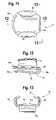
- FIG. 11is plan view of the case illustrated in FIG. 1 ;
- FIG. 12is a longitudinal sectional view taken substantially along line 12 — 12 of FIG. 11 ;
- FIG. 13is an end elevational view taken substantially along line 13 — 13 of FIG. 11 .
- the flashlight assembly 10for attachment to a support, such as an article of clothing or baggage, constructed in accordance with the principles of the present invention.
- the flashlight assembly 10includes a miniature flashlight 12 and a mating flashlight case or carrier 14 . Attaching the flashlight 12 and case 14 to a support, such as a user's hat brim, allows direction of a light beam toward a specific location, leaving both of the user's hands free for other uses.
- the flashlight 12has an overall longitudinal length of approximately 2 inches, a traverse width of approximately 0.95–1.0 inch, and a maximum transverse thickness of approximately 3 ⁇ 8 inch.
- the flashlight 12preferably uses a light emitting diode (LED) 38 as a light source and a pair of coin-type 3-volt batteries 35 a and 35 b as a power source.
- a momentary contact switch 75preferably activates the LED.
- the flashlight 12is adapted to be inserted into the case or carrier 14 in either of two positions. In one position, as illustrated in FIG. 1 , the flashlight 12 is inserted into the case 14 so that the momentary contact switch 75 is exposed upwardly, without contacting the case, thus permitting the flashlight to be in an “OFF” state. Thus oriented, the flashlight 12 will remain in an “OFF” state until the momentary contact switch 75 is manually actuated. In a second position (not shown), the flashlight 12 is rotated 180 degrees about its longitudinal axis (“flipped-over”) and inserted into the case or carrier 14 so that the momentary contact switch 75 faces the case. This causes the momentary contact switch 75 to be depressed by a portion of the case or carrier, thus maintaining the flashlight 12 in an “ON” state by interaction of the momentary contact switch against the main body 84 of the case 14 .
- the flashlight 12includes a body 16 and a top cover 18 releasably mounted on the body 16 .
- the body 16is preferably made of a plastic material that lends itself to molding.
- the body 16has a generally elliptical shape, having a forward end 20 and a rearward split-ring clip end 22 formed integrally with the body.
- the forward end 20receives and retains the light source 38 and the batteries 35 a and 35 b .
- the forward end 20also is generally oval-shaped, and has a semi-cylindrical light source receiving recess 24 formed therein.
- the light source receiving recess 24intersects the forward end 20 of the body 16 , and communicates with a channel 26 , which in turn communicates with a generally circular power source receiving recess 28 formed within the forward end 20 .
- a generally oval bottom wall 30is integrally formed with and secured to lower margins of outer sidewalls 32 a , 32 b , and to a lower margin of a wall 32 c .
- An upstanding arcuate-shaped stub wall 34preferably is formed integral with the bottom wall 30 and has an inwardly exposed arcuate surface 34 a that forms a partial boundary of the power source receiving recess 28 .
- the body 16 of the flashlight 12may be replaceable or interchangeable, allowing the flashlight to display a variety of indicia, such as text, graphics, corporate logos, and the like, which may be marked, engraved, or imprinted.
- the bottom wall 30 of the flashlight 12may be replaceable within a particular body 16 .
- the body 16 and the bottom walls 30may be made of a variety of plastic materials.
- various indiciamay be engraved, silk screened, inked, pad printed, foil stamped, or marked in any known manner. Because the body 16 and top cover 18 are manufactured as separate components of the flashlight 12 , they may be produced in different colors, allowing the flashlight to be assembled in varying and contrasting colors.
- the power sourcemay be any type of battery with sufficient power to energize the light source.
- the power sourceis preferably one or more circular batteries 35 a and 35 b having generally flat, oppositely disposed parallel sides.
- the power sourceconsists of two 3-volt lithium coin cell batteries 35 a and 35 b , such as Panasonic CR2016 batteries. Lithium batteries provide for exceptionally long life and durability, operate at a low temperature, and are leak-proof and vibration resistant.
- a pair of arcuate spacers 36 a and 36 bare preferably formed integrally with the bottom wall 30 so as to maintain the lower battery 35 b spaced slightly above the inner surface of the bottom wall 30 .
- a lower lead 38 b of the LED light source 38may be inserted so as to underlie a lower surface 37 (preferably the negative pole) of the lower battery 35 b.
- the top cover 18is also made of a plastic, moldable material, such as an elastomeric material.
- the top cover 18includes a top surface portion 44 having a generally elliptical outer peripheral edge 44 a .
- the outer peripheral edge 44 ais similar in shape to the upper marginal edges of the peripheral walls 32 a–c of the body 16 .
- the top cover 18includes depending wall segments 46 a–d that preferably are formed integral with the top surface 44 and depend from selected positions about the periphery of the top surface.
- the depending wall segments 46 a and 46 bare configured to slidably insert into recesses 48 a and 48 b respectively, formed in the body 16 .
- Depending wall segments 46 c and 46 dare also configured to slidingly engage wall surfaces 50 a and 50 b respectively, formed in body 16 .
- the top cover 18is frictionally retained in assembled relation on the body 16 .
- the top cover 18also includes a slightly forwardly extending and downwardly depending block portion 54 .
- the block portion 54fits between and cooperates with between parallel wall surfaces 56 a and 56 b ( FIG. 3 ) formed in the body 16 .
- a semi-cylindrical surface 54 a of the block portion 54overlies and compliments the semi-cylindrical surface of the light source receive recess 24 , establishing a cylindrical opening to snuggly receive and retain the LED 38 .
- the top cover 18includes a switch actuator button 60 in the form of an integral, convex, generally centrally located protrusion from the top surface 44 .
- the underside of the actuator button 60has a plurality of integrally formed concentric depending rings 62 a–d .
- the lower marginal edges of the depending rings 62 a–dgenerally lie in a common plane, substantially parallel to the upper wall 44 of the top cover 18 .
- the depending rings 62 a–dactuate the flashlight's 12 momentary contact switch 75 when it is depressed manually, or upon selective insertion of the flashlight into the case or carrier 14 .
- the actuator button's 60 elastic characteristicscause it to return to its normal configuration, as illustrated in FIG. 8 , when it is released.
- the split-ring clip end 22includes a first arcuate extension 66 formed integral with the forward portion 20 of the body 16 .
- the first arcuate extension 66is stepped at 66 a to define a lower arcuate extension 66 b that terminates at an end surface 66 c .
- the end surface 66 cis disposed opposite a stepped surface 68 a formed on a second upper arcuate extension 68 .
- the second upper arcuate extension 68also is formed integral with the forward portion 20 of the body 16 , and includes an upper arcuate extension 68 b that terminates at a terminal end surface 68 c disposed opposite the stepped surface 66 a of the first arcuate extension 66 .
- the first and second arcuate segments 66 b and 68 b of the split-ring clip end 22are resilient and have planar, laterally opposed, spaced-apart surfaces.
- one or both of the arcuate extensions 66 b and 68 bmay be spread apart from each other.
- Either of the terminal ends 66 c or 68 cmay be spread, enabling the assembled flashlight 12 to be releasably attached to a keychain, a button opening, backpacks, or other baggage, allowing hands-free use of the flashlight separately from its case 14 .
- the split-ring clip 22is extremely strong and cannot fall open accidentally.
- the unitized design of the split-ring clip 22eliminates the need for an expensive and unreliable spring-with-hub design, as is found on much of the prior art.
- an electrically nonconductive annular spacer 72overlies and contacts an upper surface 39 of the upper battery 35 a .
- the spacer 72has an electrically nonconductive, L-shaped arm 74 , having a depending portion 74 a configured to be received within a slot 70 defined in the upstanding stub wall 34 .
- the depending portion 74 a of the arm 74generally centers the annular spacer 72 on the battery 35 a.
- the spacer 72has an upstanding annular rim 72 a that forms a retaining groove to receive a conductive, circular dome plate switch 76 .
- the dome plate switch 76has a convex upper surface 76 a and a concave lower surface 76 b .
- the lower surface 76 bis spaced apart from the surface of the battery 35 a by the spacer 72 , and thus without pressure applied to the switch, it is normally out of contact with the upper battery.
- the dome plate switch 76preferably is made of a thin, flexible conductive metal, which flexes, allowing a centrally depending contact nib 76 a to contact the upper battery 35 a . When such contact occurs, a complete electrical circuit is made between the batteries 35 a , 35 b , switch 76 and LED 38 , thus activating the LED.
- the LED light source 38is placed within the light source receiving recess 24 .
- the lower lead 38 brests on the bottom wall 30 .
- the lower battery 35 bis placed within the power source receiving recess 28 .
- the lower LED lead 38 btherefore lies under, and is in contact with the lower battery 35 b .
- the upper battery 35 ais then positioned on top of the lower battery 35 b .
- the spacer 72is placed on top of the upper battery 35 a with the depending portion 74 a of the arm 74 inserted into the slot 70 .
- the dome switch place 76is then laid within the rim 72 a of the spacer 72 , with its depending contact nib 76 a adjacent the upper surface 39 of the upper battery 35 a .
- An upper lead 38 a of the LED 38then is placed on top of and in contact with the upper surface 76 a of the dome switch plate 76 .
- the top cover 18is mounted on the body 16 .
- the switch actuator button 60When the switch actuator button 60 is depressed, the annular rings 62 a–d located on the underside of the switch actuator button 60 cause the dome switch plate 76 to flex downwardly. Once the dome switch plate 76 is flexed, its contact nib 76 a engages the upper surface 39 of the upper battery 35 a .
- a circuit including LED contacts 38 a and 38 b , dome switch plate 76 , and batteries 35 a and 35 bthereby is closed, energizing the LED 38 .
- the flashlight case or carrier 14preferably is made of a rigid yet flexible plastic material.
- the case or carrier 14has a pair of generally C-shaped, laterally spaced parallel arms 80 and 82 formed integral with a connecting wall 84 .
- the arms 80 , 82 and wall 84form a generally U-shaped flashlight receiving receptacle 86 .
- the arms 80 and 82allow insertion of the flashlight 12 into the case 14 in the direction of the split-ring clip end 22 to a predetermined position (see FIG. 1 ).
- the arms 80 , 82 of the case 14frictionally contact with the opposite side walls 32 a , 32 b of the flashlight 12 . This creates a “snap-in” type of retaining arrangement.
- the connecting wallhas a crowned ridge 84 a formed at one end, and an integral, U-shaped mounting clip 90 at its other end.
- the crowned ridge 84 a of the connecting wall 84abuts the flashlight 12 when inserted, and prevents the flashlight from sliding too far into the case 14 .
- the flashlight 12When the flashlight 12 is inserted into the case 14 between the arms 80 , 82 with the switch actuator button 60 exposed upwardly, as shown in FIG. 1 , the flashlight will remain in an “OFF” state until the switch actuator button is manually depressed. In this position, the user must maintain pressure on the switch actuator button 60 to keep the LED 38 energized.
- the switch actuator button 60will activate the momentary contact switch 75 , placing the flashlight in an “ON” state until it is removed from the holder or carrier 14 .
- the U-shaped mounting clip 90facilitates attachment of the case 14 to a support, such as a hat brim, a watch strap, a belt, or other articles of clothing or baggage.
- the U-shaped mounting clip 90has a rounded, outwardly-curved free edge 90 a and an upper edge 90 b integrally connected with the connecting wall 84 . Attaching the case 14 with the mounting clip 90 allows users to aim light from the flashlight in a desired direction, thereby leaving the user's hands free for other uses.
- the mounting clip 90 of the case 14is unattached to any supports.
- the upper edge 90 blies at a distance 96 from the connecting wall 84 , while the free end 90 a rests on or nearer the connecting wall 84 (see FIG. 12 ).
- the distance from the mounting clip 90 to the case connecting wall 84is substantially the same thickness as a typical baseball-type cap brim, to allow the case 14 to attach securely to the hat brim.
- the flashlight 12is able to assume either an “OFF” state, or an “ON” while activated state within the case or carrier, it offers a simplicity and utility not found with prior art flashlights, which is valuable in both law enforcement and civilian settings.
- the flashlight 12is designed to be assembled using fully automatic equipment, completely free of human intervention. This is possible, in part, because there are few parts to place, and because the parts may be easily placed adjacent or on top of a previously placed part without complex threading or interlocking of parts.
- the flashlight componentsare all assembled from a single side. Further, the design of the flashlight allows for liberal geometric tolerances, which facilitates the use of fully automatic assembly equipment. Automation of the assembly process dramatically increases the speed at which the flashlights 12 may be produced, as well as lowers the price per unit.
Landscapes
- Engineering & Computer Science (AREA)
- General Engineering & Computer Science (AREA)
- Arrangement Of Elements, Cooling, Sealing, Or The Like Of Lighting Devices (AREA)
- Purses, Travelling Bags, Baskets, Or Suitcases (AREA)
Abstract
Description
Claims (39)
Priority Applications (1)
| Application Number | Priority Date | Filing Date | Title |
|---|---|---|---|
| US10/624,216US7021790B2 (en) | 2003-07-22 | 2003-07-22 | Miniature LED flashlight with snap-on carrier |
Applications Claiming Priority (1)
| Application Number | Priority Date | Filing Date | Title |
|---|---|---|---|
| US10/624,216US7021790B2 (en) | 2003-07-22 | 2003-07-22 | Miniature LED flashlight with snap-on carrier |
Publications (2)
| Publication Number | Publication Date |
|---|---|
| US20050018420A1 US20050018420A1 (en) | 2005-01-27 |
| US7021790B2true US7021790B2 (en) | 2006-04-04 |
Family
ID=34079950
Family Applications (1)
| Application Number | Title | Priority Date | Filing Date |
|---|---|---|---|
| US10/624,216Expired - Fee RelatedUS7021790B2 (en) | 2003-07-22 | 2003-07-22 | Miniature LED flashlight with snap-on carrier |
Country Status (1)
| Country | Link |
|---|---|
| US (1) | US7021790B2 (en) |
Cited By (54)
| Publication number | Priority date | Publication date | Assignee | Title |
|---|---|---|---|---|
| US20060039130A1 (en)* | 2004-08-18 | 2006-02-23 | Yazaki Corporation | Pointer |
| US20060215394A1 (en)* | 2005-03-24 | 2006-09-28 | Cyberlux Corporation | Key cap having integral LED |
| US20080137326A1 (en)* | 2006-12-08 | 2008-06-12 | Levine Jonathan E | Lighting device with clip |
| USD598797S1 (en)* | 2008-04-09 | 2009-08-25 | Mitsubishi Electric Corporation | Remote controller for vehicles |
| US20090293334A1 (en)* | 2008-04-18 | 2009-12-03 | S&S Precision, Llc | Firearm fastener |
| US20100128470A1 (en)* | 2008-11-21 | 2010-05-27 | V-Lite Usa | Illuminating device and method |
| USD617025S1 (en) | 2009-10-26 | 2010-06-01 | Levine Jonathan E | Lighting device |
| US20100182563A1 (en)* | 2001-11-07 | 2010-07-22 | Michael Waters | Lighted Reading Glasses |
| US20100295484A1 (en)* | 2008-01-30 | 2010-11-25 | Carson Kelly Smith | Lock Light |
| US20110013135A1 (en)* | 2001-11-07 | 2011-01-20 | Michael Waters | Illuminated eyewear |
| US20110075095A1 (en)* | 2009-09-30 | 2011-03-31 | Michael Waters | Illuminated eyewear |
| USD636913S1 (en)* | 2010-03-30 | 2011-04-26 | Halaquist Philip W | Light device |
| US20110122601A1 (en)* | 2007-12-18 | 2011-05-26 | Michael Waters | Illuminated headgear having switch devices and packaging therefor |
| US20110211156A1 (en)* | 2007-10-29 | 2011-09-01 | Edward Beiner | Illuminated Eyeglass Assembly |
| US20110228211A1 (en)* | 2001-11-07 | 2011-09-22 | Michael Waters | Lighted reading glasses |
| US20120116368A1 (en)* | 2010-11-10 | 2012-05-10 | Viola Frank J | Surgical instrument with add-on power adapter for accessory |
| US8333485B2 (en) | 2007-12-18 | 2012-12-18 | Michael Waters | Headwear with switch shielding portion |
| US8388164B2 (en) | 2005-05-17 | 2013-03-05 | Michael Waters | Hands-Free lighting devices |
| USD677433S1 (en) | 2012-03-27 | 2013-03-05 | S & S Precision, Llc | Plate carrier vest |
| USD682343S1 (en) | 2011-12-23 | 2013-05-14 | Michael Waters | Lighted glasses |
| US8540364B2 (en) | 2010-09-14 | 2013-09-24 | Michael Waters | Lighted glasses |
| US8545012B2 (en) | 2005-05-17 | 2013-10-01 | Michael Waters | Illuminated eyewear |
| US8550651B2 (en) | 2007-12-18 | 2013-10-08 | Waters Industries, Inc. | Lighted hat |
| US8650794B2 (en) | 2008-04-18 | 2014-02-18 | S&S Precision, Llc | Firearm fastener |
| US8727556B2 (en) | 2010-09-02 | 2014-05-20 | S & S Precision, Llc | Integrated illumination device mount |
| US8757831B2 (en) | 2007-12-18 | 2014-06-24 | Michael Waters | Headgear having an electrical device and power source mounted thereto |
| US8882292B2 (en) | 2008-11-21 | 2014-11-11 | S & S Precision, Llc | Multi-spectrum lighting device with plurality of switches |
| US8979295B2 (en) | 2005-05-17 | 2015-03-17 | Michael Waters | Rechargeable lighted glasses |
| US9101174B2 (en) | 2011-11-04 | 2015-08-11 | Michael Waters | Hat with automated shut-off feature for electrical devices |
| US9144261B2 (en) | 2014-10-16 | 2015-09-29 | Arcachon Holdings Llc | Combination marker light and infrared interrogation device |
| US9175837B1 (en) | 2014-10-16 | 2015-11-03 | Arcachon Holdings Llc | Marker system |
| US9341714B2 (en) | 2014-10-16 | 2016-05-17 | Arcachon Holdings Llc | Marker system |
| USD770143S1 (en) | 2014-05-23 | 2016-11-01 | Michael Waters | Beanie with means for illumination |
| US20160361133A1 (en)* | 2015-06-03 | 2016-12-15 | James M. Davis | Light Carrier And System For Mounting Same To A Surgical Instrument |
| US9526292B2 (en) | 2005-05-17 | 2016-12-27 | Michael Waters | Power modules and headgear |
| US9526287B2 (en) | 2011-12-23 | 2016-12-27 | Michael Waters | Lighted hat |
| US9568173B2 (en) | 2011-12-23 | 2017-02-14 | Michael Waters | Lighted hat |
| US9609902B2 (en) | 2011-12-23 | 2017-04-04 | Michael Waters | Headgear having a camera device |
| US9717633B2 (en) | 2013-03-15 | 2017-08-01 | Michael Waters | Lighted headgear |
| US9746561B2 (en) | 2014-10-16 | 2017-08-29 | Arcachon Holdings Llc | Marker system |
| US9777997B2 (en) | 2011-10-03 | 2017-10-03 | S&S Precision, Llc | Plate carrier apparatus and method |
| US9872530B2 (en) | 2010-04-30 | 2018-01-23 | Michael Waters | Lighted headgear and accessories therefor |
| USD824557S1 (en) | 2014-12-02 | 2018-07-31 | Michael Waters | Flashlight |
| US10069318B2 (en) | 2014-12-02 | 2018-09-04 | Michael Waters | LED flashlight with longitudinal cooling fins |
| US10159294B2 (en) | 2012-12-19 | 2018-12-25 | Michael Waters | Lighted solar hat |
| USD838022S1 (en) | 2017-06-24 | 2019-01-08 | Arcachon Holdings Llc | Marker system |
| US10466011B2 (en) | 2017-01-01 | 2019-11-05 | S&S Precision, Llc | Weapon and accessory link |
| US10791783B1 (en) | 2019-05-16 | 2020-10-06 | Waters Industries, Inc. | Lighted headgear and accessories therefor |
| US10897805B2 (en) | 2015-05-18 | 2021-01-19 | Arcachon Holdings Llc | System, method, and apparatus for synchronizing flashing in a marker system |
| US11049379B2 (en) | 2015-05-18 | 2021-06-29 | Arcachon Holdings Llc | Marker system with zone notification |
| US11047984B2 (en) | 2015-05-18 | 2021-06-29 | Arcachon Holdings Llc | System, method, and apparatus for synchronizing local flashing in a marker system |
| US11139130B1 (en) | 2021-02-09 | 2021-10-05 | Arcachon Holdings Llc | Safety switch |
| US11771164B2 (en) | 2015-05-18 | 2023-10-03 | Arcachon Holdings Llc | System, method, and apparatus for synchronizing local flashing in a marker system |
| US12171293B2 (en) | 2021-12-27 | 2024-12-24 | Waters Industries, Inc. | Lighted headgear and accessories therefor |
Families Citing this family (15)
| Publication number | Priority date | Publication date | Assignee | Title |
|---|---|---|---|---|
| JP4371987B2 (en)* | 2004-12-07 | 2009-11-25 | ホシデン株式会社 | Push-on switch |
| US20070217184A1 (en)* | 2006-03-16 | 2007-09-20 | James Berry | LED light assembly |
| CN201215253Y (en)* | 2006-06-16 | 2009-04-01 | 阿吉特·库巴尼 | Portable and mountable light bulb and fixture |
| USD566875S1 (en) | 2006-07-06 | 2008-04-15 | Ajit Khubani | Combined portable, mountable light and holder therefore |
| EP2478294A1 (en)* | 2009-09-16 | 2012-07-25 | Sight Saver, LLC | Light system |
| US8579478B2 (en) | 2010-06-23 | 2013-11-12 | Sight Saver, Llc | Attachable illumination system |
| WO2013066997A2 (en) | 2011-11-03 | 2013-05-10 | Sight Saver, Llc | Ratchet clip |
| WO2014124385A1 (en)* | 2013-02-08 | 2014-08-14 | Zealer Carl | Illumination device |
| US20150116992A1 (en)* | 2013-10-28 | 2015-04-30 | Johnny Ray Massey | LED device for lighting a fishing line at the pole |
| CN105023987B (en)* | 2014-04-23 | 2018-01-09 | 光宝光电(常州)有限公司 | LED load bearing seats and its manufacture method |
| CN108606417B (en)* | 2018-07-09 | 2021-04-20 | 安徽新大陆特种涂料有限责任公司 | Ring clamping device |
| JP1640900S (en)* | 2018-08-31 | 2019-09-09 | ||
| US10986887B1 (en)* | 2019-11-13 | 2021-04-27 | Rubies Ii, Llc | Detachable illuminating costume accessory |
| USD963218S1 (en)* | 2020-12-01 | 2022-09-06 | Streamlight, Inc. | Lighting device |
| US20240304121A1 (en)* | 2023-03-06 | 2024-09-12 | Dennis Spencer | Illuminated safety flag device |
Citations (27)
| Publication number | Priority date | Publication date | Assignee | Title |
|---|---|---|---|---|
| US1572210A (en) | 1926-02-09 | Combined visor and automatic flash light | ||
| US2524881A (en) | 1948-05-24 | 1950-10-10 | Chambers Harvey Frederick | Combined clasp and lighting implement |
| US3256428A (en) | 1963-07-29 | 1966-06-14 | Bantam Lite Inc | Miniaturized flashlight with replacement cartridge unit |
| US3296429A (en) | 1964-06-29 | 1967-01-03 | Schwartz Sidney | Keycase-flashlight construction |
| US4406040A (en) | 1978-11-27 | 1983-09-27 | Cannone Robert P | Illumination devices |
| US4750095A (en) | 1986-08-11 | 1988-06-07 | Huang Tien Tsai | Auto-lighting flashlight assembly |
| US4967323A (en) | 1989-11-01 | 1990-10-30 | Melissa C. Johnson | Adjustable apparel-held flashlight |
| US5199780A (en) | 1992-02-14 | 1993-04-06 | Ekman John M | Flashlight hat clip |
| US5284345A (en) | 1992-10-26 | 1994-02-08 | Jehn E F | Laser indicator to be used in golf training |
| USD354677S (en) | 1993-06-01 | 1995-01-24 | Troyer Larry D | Clip for a flashlight |
| US5541816A (en) | 1995-06-07 | 1996-07-30 | Miserendino; Nicholas G. | Clip light source |
| US5722762A (en) | 1996-07-18 | 1998-03-03 | Soll; David B. | Illumination device for mounting on the head of a user |
| US5893496A (en) | 1995-08-01 | 1999-04-13 | Katz; Rodney | Utility headband and holster system |
| USD425226S (en) | 1999-08-11 | 2000-05-16 | Emissive Energy Corporation | Miniature flashlight |
| US6119864A (en) | 1999-04-28 | 2000-09-19 | Kessler; Henry M. | Storage device to accommodate batteries of varying sizes |
| US6168286B1 (en) | 1998-08-03 | 2001-01-02 | Paul J. Duffy | Brim mounted novelty light for sports caps |
| US6190018B1 (en) | 1999-01-06 | 2001-02-20 | Armament Systems And Procedures, Inc. | Miniature LED flashlight |
| US6206543B1 (en) | 1999-11-12 | 2001-03-27 | David Vincent Henry | Flashlight holder assembly |
| US6302558B1 (en) | 1999-10-29 | 2001-10-16 | Robert Parks | Portable safety device |
| US6398383B1 (en) | 2000-10-30 | 2002-06-04 | Yu-Hwei Huang | Flashlight carriable on one's person |
| US20020093818A1 (en) | 2001-01-18 | 2002-07-18 | Teketite Industries, Inc. | Miniature high power flashlight |
| US6428180B1 (en) | 1999-07-20 | 2002-08-06 | Mickey M. Karram | Surgical illumination device and method of use |
| US6467929B2 (en) | 1999-09-20 | 2002-10-22 | Razgo Lee | Apparatus for attaching or mounting a laser diode module |
| US6523973B2 (en) | 1999-08-16 | 2003-02-25 | Robert D. Galli | Miniature flashlight |
| US6530672B2 (en) | 1999-08-16 | 2003-03-11 | Robert D. Galli | Miniature flashlight |
| US6609811B1 (en)* | 2000-10-06 | 2003-08-26 | Streamlight, Inc. | Handcuff key light |
| US6619813B1 (en)* | 2002-03-19 | 2003-09-16 | Ip Holdings, Inc. | Multi-purpose LED light |
- 2003
- 2003-07-22USUS10/624,216patent/US7021790B2/ennot_activeExpired - Fee Related
Patent Citations (27)
| Publication number | Priority date | Publication date | Assignee | Title |
|---|---|---|---|---|
| US1572210A (en) | 1926-02-09 | Combined visor and automatic flash light | ||
| US2524881A (en) | 1948-05-24 | 1950-10-10 | Chambers Harvey Frederick | Combined clasp and lighting implement |
| US3256428A (en) | 1963-07-29 | 1966-06-14 | Bantam Lite Inc | Miniaturized flashlight with replacement cartridge unit |
| US3296429A (en) | 1964-06-29 | 1967-01-03 | Schwartz Sidney | Keycase-flashlight construction |
| US4406040A (en) | 1978-11-27 | 1983-09-27 | Cannone Robert P | Illumination devices |
| US4750095A (en) | 1986-08-11 | 1988-06-07 | Huang Tien Tsai | Auto-lighting flashlight assembly |
| US4967323A (en) | 1989-11-01 | 1990-10-30 | Melissa C. Johnson | Adjustable apparel-held flashlight |
| US5199780A (en) | 1992-02-14 | 1993-04-06 | Ekman John M | Flashlight hat clip |
| US5284345A (en) | 1992-10-26 | 1994-02-08 | Jehn E F | Laser indicator to be used in golf training |
| USD354677S (en) | 1993-06-01 | 1995-01-24 | Troyer Larry D | Clip for a flashlight |
| US5541816A (en) | 1995-06-07 | 1996-07-30 | Miserendino; Nicholas G. | Clip light source |
| US5893496A (en) | 1995-08-01 | 1999-04-13 | Katz; Rodney | Utility headband and holster system |
| US5722762A (en) | 1996-07-18 | 1998-03-03 | Soll; David B. | Illumination device for mounting on the head of a user |
| US6168286B1 (en) | 1998-08-03 | 2001-01-02 | Paul J. Duffy | Brim mounted novelty light for sports caps |
| US6190018B1 (en) | 1999-01-06 | 2001-02-20 | Armament Systems And Procedures, Inc. | Miniature LED flashlight |
| US6119864A (en) | 1999-04-28 | 2000-09-19 | Kessler; Henry M. | Storage device to accommodate batteries of varying sizes |
| US6428180B1 (en) | 1999-07-20 | 2002-08-06 | Mickey M. Karram | Surgical illumination device and method of use |
| USD425226S (en) | 1999-08-11 | 2000-05-16 | Emissive Energy Corporation | Miniature flashlight |
| US6523973B2 (en) | 1999-08-16 | 2003-02-25 | Robert D. Galli | Miniature flashlight |
| US6530672B2 (en) | 1999-08-16 | 2003-03-11 | Robert D. Galli | Miniature flashlight |
| US6467929B2 (en) | 1999-09-20 | 2002-10-22 | Razgo Lee | Apparatus for attaching or mounting a laser diode module |
| US6302558B1 (en) | 1999-10-29 | 2001-10-16 | Robert Parks | Portable safety device |
| US6206543B1 (en) | 1999-11-12 | 2001-03-27 | David Vincent Henry | Flashlight holder assembly |
| US6609811B1 (en)* | 2000-10-06 | 2003-08-26 | Streamlight, Inc. | Handcuff key light |
| US6398383B1 (en) | 2000-10-30 | 2002-06-04 | Yu-Hwei Huang | Flashlight carriable on one's person |
| US20020093818A1 (en) | 2001-01-18 | 2002-07-18 | Teketite Industries, Inc. | Miniature high power flashlight |
| US6619813B1 (en)* | 2002-03-19 | 2003-09-16 | Ip Holdings, Inc. | Multi-purpose LED light |
Cited By (78)
| Publication number | Priority date | Publication date | Assignee | Title |
|---|---|---|---|---|
| US20110013135A1 (en)* | 2001-11-07 | 2011-01-20 | Michael Waters | Illuminated eyewear |
| US8152330B2 (en) | 2001-11-07 | 2012-04-10 | Michael Waters | Lighted reading glasses |
| US8899744B2 (en) | 2001-11-07 | 2014-12-02 | Michael Waters | Lighted reading glasses |
| US20110228211A1 (en)* | 2001-11-07 | 2011-09-22 | Michael Waters | Lighted reading glasses |
| US8491118B2 (en) | 2001-11-07 | 2013-07-23 | Michael Waters | Lighted reading glasses |
| US8235524B2 (en) | 2001-11-07 | 2012-08-07 | Michael Waters | Illuminated eyewear |
| US20100182563A1 (en)* | 2001-11-07 | 2010-07-22 | Michael Waters | Lighted Reading Glasses |
| US20060039130A1 (en)* | 2004-08-18 | 2006-02-23 | Yazaki Corporation | Pointer |
| US7635192B2 (en)* | 2004-08-18 | 2009-12-22 | Yazaki Corporation | Pointer having a curved Reflective Surface |
| US20060215394A1 (en)* | 2005-03-24 | 2006-09-28 | Cyberlux Corporation | Key cap having integral LED |
| US8545012B2 (en) | 2005-05-17 | 2013-10-01 | Michael Waters | Illuminated eyewear |
| US8388164B2 (en) | 2005-05-17 | 2013-03-05 | Michael Waters | Hands-Free lighting devices |
| US9513495B2 (en) | 2005-05-17 | 2016-12-06 | Michael Waters | Illuminated eyewear |
| US8979295B2 (en) | 2005-05-17 | 2015-03-17 | Michael Waters | Rechargeable lighted glasses |
| US9526292B2 (en) | 2005-05-17 | 2016-12-27 | Michael Waters | Power modules and headgear |
| US7699492B2 (en)* | 2006-12-08 | 2010-04-20 | Levine Jonathan E | Lighting device with clip |
| US20080137326A1 (en)* | 2006-12-08 | 2008-06-12 | Levine Jonathan E | Lighting device with clip |
| US20110211156A1 (en)* | 2007-10-29 | 2011-09-01 | Edward Beiner | Illuminated Eyeglass Assembly |
| US8485682B2 (en) | 2007-10-29 | 2013-07-16 | Waters Industries, Inc. | Illuminated eyeglass assembly |
| US20110122601A1 (en)* | 2007-12-18 | 2011-05-26 | Michael Waters | Illuminated headgear having switch devices and packaging therefor |
| US9185278B2 (en) | 2007-12-18 | 2015-11-10 | Michael Waters | Hands free lighting devices |
| US8333485B2 (en) | 2007-12-18 | 2012-12-18 | Michael Waters | Headwear with switch shielding portion |
| US8757831B2 (en) | 2007-12-18 | 2014-06-24 | Michael Waters | Headgear having an electrical device and power source mounted thereto |
| US8550651B2 (en) | 2007-12-18 | 2013-10-08 | Waters Industries, Inc. | Lighted hat |
| US9585431B2 (en) | 2007-12-18 | 2017-03-07 | Waters Industries, Inc. | Lighted hat |
| US8491145B2 (en) | 2007-12-18 | 2013-07-23 | Waters Industries, Inc. | Illuminated headgear having switch devices and packaging therefor |
| US20100295484A1 (en)* | 2008-01-30 | 2010-11-25 | Carson Kelly Smith | Lock Light |
| USD598797S1 (en)* | 2008-04-09 | 2009-08-25 | Mitsubishi Electric Corporation | Remote controller for vehicles |
| US8166694B2 (en) | 2008-04-18 | 2012-05-01 | S&S Precision, Llc | Firearm securing device and method |
| US20090293334A1 (en)* | 2008-04-18 | 2009-12-03 | S&S Precision, Llc | Firearm fastener |
| US8650794B2 (en) | 2008-04-18 | 2014-02-18 | S&S Precision, Llc | Firearm fastener |
| US20100128470A1 (en)* | 2008-11-21 | 2010-05-27 | V-Lite Usa | Illuminating device and method |
| US8444291B2 (en)* | 2008-11-21 | 2013-05-21 | S&S Precision, Llc | LED illuminating device for use during tactical operations, and method |
| US8882292B2 (en) | 2008-11-21 | 2014-11-11 | S & S Precision, Llc | Multi-spectrum lighting device with plurality of switches |
| US8444266B2 (en) | 2009-09-30 | 2013-05-21 | Michael Waters | Illuminated eyewear |
| US8567945B2 (en) | 2009-09-30 | 2013-10-29 | Michael Waters | Illuminated eyewear |
| US20110075095A1 (en)* | 2009-09-30 | 2011-03-31 | Michael Waters | Illuminated eyewear |
| USD617025S1 (en) | 2009-10-26 | 2010-06-01 | Levine Jonathan E | Lighting device |
| USD636913S1 (en)* | 2010-03-30 | 2011-04-26 | Halaquist Philip W | Light device |
| US9872530B2 (en) | 2010-04-30 | 2018-01-23 | Michael Waters | Lighted headgear and accessories therefor |
| US10117476B2 (en) | 2010-04-30 | 2018-11-06 | Michael Waters | Lighted headgear and accessories therefor |
| US10716350B2 (en) | 2010-04-30 | 2020-07-21 | Michael Waters | Lighted headgear and accessories therefor |
| US11478035B2 (en) | 2010-04-30 | 2022-10-25 | Michael Waters | Lighted headgear and accessories therefor |
| US8727556B2 (en) | 2010-09-02 | 2014-05-20 | S & S Precision, Llc | Integrated illumination device mount |
| US8540364B2 (en) | 2010-09-14 | 2013-09-24 | Michael Waters | Lighted glasses |
| US20120116368A1 (en)* | 2010-11-10 | 2012-05-10 | Viola Frank J | Surgical instrument with add-on power adapter for accessory |
| US9777997B2 (en) | 2011-10-03 | 2017-10-03 | S&S Precision, Llc | Plate carrier apparatus and method |
| US9101174B2 (en) | 2011-11-04 | 2015-08-11 | Michael Waters | Hat with automated shut-off feature for electrical devices |
| USD682343S1 (en) | 2011-12-23 | 2013-05-14 | Michael Waters | Lighted glasses |
| US9526287B2 (en) | 2011-12-23 | 2016-12-27 | Michael Waters | Lighted hat |
| US9568173B2 (en) | 2011-12-23 | 2017-02-14 | Michael Waters | Lighted hat |
| US9609902B2 (en) | 2011-12-23 | 2017-04-04 | Michael Waters | Headgear having a camera device |
| USD677433S1 (en) | 2012-03-27 | 2013-03-05 | S & S Precision, Llc | Plate carrier vest |
| US10159294B2 (en) | 2012-12-19 | 2018-12-25 | Michael Waters | Lighted solar hat |
| US9717633B2 (en) | 2013-03-15 | 2017-08-01 | Michael Waters | Lighted headgear |
| USD770143S1 (en) | 2014-05-23 | 2016-11-01 | Michael Waters | Beanie with means for illumination |
| US9144261B2 (en) | 2014-10-16 | 2015-09-29 | Arcachon Holdings Llc | Combination marker light and infrared interrogation device |
| US9175838B1 (en) | 2014-10-16 | 2015-11-03 | Arcachon Holdings Llc | Combination marker light and infrared interrogation device |
| US9175837B1 (en) | 2014-10-16 | 2015-11-03 | Arcachon Holdings Llc | Marker system |
| US9476982B2 (en) | 2014-10-16 | 2016-10-25 | Arcachon Holdings Llc | Marker system |
| US9341714B2 (en) | 2014-10-16 | 2016-05-17 | Arcachon Holdings Llc | Marker system |
| US9746561B2 (en) | 2014-10-16 | 2017-08-29 | Arcachon Holdings Llc | Marker system |
| USD824557S1 (en) | 2014-12-02 | 2018-07-31 | Michael Waters | Flashlight |
| US10069318B2 (en) | 2014-12-02 | 2018-09-04 | Michael Waters | LED flashlight with longitudinal cooling fins |
| US10847985B2 (en) | 2014-12-02 | 2020-11-24 | Michael Waters | Flashlight with longitudinal cooling fins |
| US10897805B2 (en) | 2015-05-18 | 2021-01-19 | Arcachon Holdings Llc | System, method, and apparatus for synchronizing flashing in a marker system |
| US11049379B2 (en) | 2015-05-18 | 2021-06-29 | Arcachon Holdings Llc | Marker system with zone notification |
| US11047984B2 (en) | 2015-05-18 | 2021-06-29 | Arcachon Holdings Llc | System, method, and apparatus for synchronizing local flashing in a marker system |
| US12096813B2 (en) | 2015-05-18 | 2024-09-24 | Arcachon Holdings Llc | System, method, and apparatus for detecting IR radiation in a marker system |
| US11771164B2 (en) | 2015-05-18 | 2023-10-03 | Arcachon Holdings Llc | System, method, and apparatus for synchronizing local flashing in a marker system |
| US10463444B2 (en)* | 2015-06-03 | 2019-11-05 | Sunoptic Technologies Llc | Light carrier and system for mounting same to a surgical instrument |
| US20160361133A1 (en)* | 2015-06-03 | 2016-12-15 | James M. Davis | Light Carrier And System For Mounting Same To A Surgical Instrument |
| US10466011B2 (en) | 2017-01-01 | 2019-11-05 | S&S Precision, Llc | Weapon and accessory link |
| USD838022S1 (en) | 2017-06-24 | 2019-01-08 | Arcachon Holdings Llc | Marker system |
| US10791783B1 (en) | 2019-05-16 | 2020-10-06 | Waters Industries, Inc. | Lighted headgear and accessories therefor |
| US11206888B2 (en) | 2019-05-16 | 2021-12-28 | Waters Industries, Inc. | Lighted headgear and accessories therefor |
| US11139130B1 (en) | 2021-02-09 | 2021-10-05 | Arcachon Holdings Llc | Safety switch |
| US12171293B2 (en) | 2021-12-27 | 2024-12-24 | Waters Industries, Inc. | Lighted headgear and accessories therefor |
Also Published As
| Publication number | Publication date |
|---|---|
| US20050018420A1 (en) | 2005-01-27 |
Similar Documents
| Publication | Publication Date | Title |
|---|---|---|
| US7021790B2 (en) | Miniature LED flashlight with snap-on carrier | |
| US7172309B2 (en) | Miniature LED flashlight having split ring | |
| US6190018B1 (en) | Miniature LED flashlight | |
| US7147344B2 (en) | LED flashlight with switch element in side surface | |
| US6511214B1 (en) | Miniature LED flashlight | |
| US6357890B1 (en) | Miniature LED flashlight | |
| US6953259B2 (en) | Adjustable flashlight case | |
| US6923551B2 (en) | Flashlight mounting system | |
| US6840650B2 (en) | Miniature flashlight having replaceable battery pack | |
| US20010038534A1 (en) | Minature flashlight | |
| US6942357B2 (en) | Miniature flashlight having replaceable battery pack and multiple operating modes | |
| US7261433B2 (en) | Miniature flashlight having replaceable battery pack and multiple operating modes | |
| US6786616B1 (en) | LED flashlight with switch separate from panel | |
| US7186001B1 (en) | LED flashlight having clip extending from frame | |
| US6749317B1 (en) | Miniature led flashlight | |
| US6666564B1 (en) | LED pen clip | |
| US20060007676A1 (en) | Flashlight | |
| KR910003116Y1 (en) | A key holder |
Legal Events
| Date | Code | Title | Description |
|---|---|---|---|
| AS | Assignment | Owner name:ARMAMENT SYSTEMS AND PROCEDURES, INC., WISCONSIN Free format text:ASSIGNMENT OF ASSIGNORS INTEREST;ASSIGNOR:PARSONS;REEL/FRAME:014325/0155 Effective date:20030717 | |
| AS | Assignment | Owner name:M&I MARSHALL & ILSLEY BANK, WISCONSIN Free format text:SECURITY AGREEMENT;ASSIGNOR:ARMAMENT SYSTEMS AND PROCEDURES, INC.;REEL/FRAME:021029/0361 Effective date:20080502 Owner name:M&I MARSHALL & ILSLEY BANK,WISCONSIN Free format text:SECURITY AGREEMENT;ASSIGNOR:ARMAMENT SYSTEMS AND PROCEDURES, INC.;REEL/FRAME:021029/0361 Effective date:20080502 | |
| AS | Assignment | Owner name:EMISSIVE ENERGY CORPORATION, RHODE ISLAND Free format text:SECURITY AGREEMENT;ASSIGNOR:ARMAMENT SYSTEMS AND PROCEDURES, INC.;REEL/FRAME:021064/0057 Effective date:20080502 Owner name:I.Q. HONG KONG LIMITED, HONG KONG Free format text:SECURITY AGREEMENT;ASSIGNOR:ARMAMENT SYSTEMS AND PROCEDURES, INC.;REEL/FRAME:021064/0057 Effective date:20080502 Owner name:ZEN DESIGN GROUP LIMITED, MICHIGAN Free format text:SECURITY AGREEMENT;ASSIGNOR:ARMAMENT SYSTEMS AND PROCEDURES, INC.;REEL/FRAME:021064/0057 Effective date:20080502 Owner name:VECTOR PRODUCTS, INC., FLORIDA Free format text:SECURITY AGREEMENT;ASSIGNOR:ARMAMENT SYSTEMS AND PROCEDURES, INC.;REEL/FRAME:021064/0057 Effective date:20080502 Owner name:TARGET CORPORATION, MINNESOTA Free format text:SECURITY AGREEMENT;ASSIGNOR:ARMAMENT SYSTEMS AND PROCEDURES, INC.;REEL/FRAME:021064/0057 Effective date:20080502 Owner name:EMISSIVE ENERGY CORPORATION,RHODE ISLAND Free format text:SECURITY AGREEMENT;ASSIGNOR:ARMAMENT SYSTEMS AND PROCEDURES, INC.;REEL/FRAME:021064/0057 Effective date:20080502 Owner name:I.Q. HONG KONG LIMITED,HONG KONG Free format text:SECURITY AGREEMENT;ASSIGNOR:ARMAMENT SYSTEMS AND PROCEDURES, INC.;REEL/FRAME:021064/0057 Effective date:20080502 Owner name:ZEN DESIGN GROUP LIMITED,MICHIGAN Free format text:SECURITY AGREEMENT;ASSIGNOR:ARMAMENT SYSTEMS AND PROCEDURES, INC.;REEL/FRAME:021064/0057 Effective date:20080502 Owner name:VECTOR PRODUCTS, INC.,FLORIDA Free format text:SECURITY AGREEMENT;ASSIGNOR:ARMAMENT SYSTEMS AND PROCEDURES, INC.;REEL/FRAME:021064/0057 Effective date:20080502 Owner name:TARGET CORPORATION,MINNESOTA Free format text:SECURITY AGREEMENT;ASSIGNOR:ARMAMENT SYSTEMS AND PROCEDURES, INC.;REEL/FRAME:021064/0057 Effective date:20080502 | |
| FPAY | Fee payment | Year of fee payment:4 | |
| AS | Assignment | Owner name:ARMAMENT SYSTEMS AND PROCEDURES, INC., WISCONSIN Free format text:RELEASE BY SECURED PARTY;ASSIGNORS:EMISSIVE ENERGY COPRORATION;I.Q. HONG KONG LIMITED;ZEN DESIGN GROUP LIMITED;AND OTHERS;REEL/FRAME:026877/0699 Effective date:20110725 | |
| FPAY | Fee payment | Year of fee payment:8 | |
| FPAY | Fee payment | Year of fee payment:8 | |
| FEPP | Fee payment procedure | Free format text:MAINTENANCE FEE REMINDER MAILED (ORIGINAL EVENT CODE: REM.) | |
| LAPS | Lapse for failure to pay maintenance fees | Free format text:PATENT EXPIRED FOR FAILURE TO PAY MAINTENANCE FEES (ORIGINAL EVENT CODE: EXP.) | |
| STCH | Information on status: patent discontinuation | Free format text:PATENT EXPIRED DUE TO NONPAYMENT OF MAINTENANCE FEES UNDER 37 CFR 1.362 | |
| FP | Lapsed due to failure to pay maintenance fee | Effective date:20180404 |