US7021442B2 - One-way torque transmitter with a friction actuating apparatus - Google Patents
One-way torque transmitter with a friction actuating apparatusDownload PDFInfo
- Publication number
- US7021442B2 US7021442B2US10/801,790US80179004AUS7021442B2US 7021442 B2US7021442 B2US 7021442B2US 80179004 AUS80179004 AUS 80179004AUS 7021442 B2US7021442 B2US 7021442B2
- Authority
- US
- United States
- Prior art keywords
- torque
- friction
- thrust
- way
- transmitting mechanism
- Prior art date
- Legal status (The legal status is an assumption and is not a legal conclusion. Google has not performed a legal analysis and makes no representation as to the accuracy of the status listed.)
- Expired - Lifetime, expires
Links
- 230000007246mechanismEffects0.000claimsabstractdescription56
- 230000005540biological transmissionEffects0.000description4
- 239000012530fluidSubstances0.000description3
- 238000005086pumpingMethods0.000description1
Images


Classifications
- F—MECHANICAL ENGINEERING; LIGHTING; HEATING; WEAPONS; BLASTING
- F16—ENGINEERING ELEMENTS AND UNITS; GENERAL MEASURES FOR PRODUCING AND MAINTAINING EFFECTIVE FUNCTIONING OF MACHINES OR INSTALLATIONS; THERMAL INSULATION IN GENERAL
- F16D—COUPLINGS FOR TRANSMITTING ROTATION; CLUTCHES; BRAKES
- F16D28/00—Electrically-actuated clutches
- F—MECHANICAL ENGINEERING; LIGHTING; HEATING; WEAPONS; BLASTING
- F16—ENGINEERING ELEMENTS AND UNITS; GENERAL MEASURES FOR PRODUCING AND MAINTAINING EFFECTIVE FUNCTIONING OF MACHINES OR INSTALLATIONS; THERMAL INSULATION IN GENERAL
- F16D—COUPLINGS FOR TRANSMITTING ROTATION; CLUTCHES; BRAKES
- F16D29/00—Clutches and systems of clutches involving both fluid and magnetic actuation
- F16D29/005—Clutches and systems of clutches involving both fluid and magnetic actuation with a fluid pressure piston driven by an electric motor
- F—MECHANICAL ENGINEERING; LIGHTING; HEATING; WEAPONS; BLASTING
- F16—ENGINEERING ELEMENTS AND UNITS; GENERAL MEASURES FOR PRODUCING AND MAINTAINING EFFECTIVE FUNCTIONING OF MACHINES OR INSTALLATIONS; THERMAL INSULATION IN GENERAL
- F16D—COUPLINGS FOR TRANSMITTING ROTATION; CLUTCHES; BRAKES
- F16D23/00—Details of mechanically-actuated clutches not specific for one distinct type
- F16D23/12—Mechanical clutch-actuating mechanisms arranged outside the clutch as such
- F16D2023/123—Clutch actuation by cams, ramps or ball-screw mechanisms
- F—MECHANICAL ENGINEERING; LIGHTING; HEATING; WEAPONS; BLASTING
- F16—ENGINEERING ELEMENTS AND UNITS; GENERAL MEASURES FOR PRODUCING AND MAINTAINING EFFECTIVE FUNCTIONING OF MACHINES OR INSTALLATIONS; THERMAL INSULATION IN GENERAL
- F16D—COUPLINGS FOR TRANSMITTING ROTATION; CLUTCHES; BRAKES
- F16D27/00—Magnetically- or electrically- actuated clutches; Control or electric circuits therefor
- F16D27/004—Magnetically- or electrically- actuated clutches; Control or electric circuits therefor with permanent magnets combined with electromagnets
Definitions
- This inventionrelates to one-way torque-transmitting mechanisms for use with torque-to-thrust apparatus.
- One-way torque-transmitting mechanisms or Mechanical Diodesgenerally are sprag, roller, or strut type and are designed to prevent overrunning between two members in one direction of operation while permitting overrunning of a member in the opposite direction. These devices might either be torque-transmitting mechanisms of the rotating type or torque-transmitting mechanisms providing a stationary operation such as a brake. These one-way devices have found a lot of use in power transmission situations wherein it is desirable to establish at least one ratio such that on a ratio interchange, the one-way device will simply overrun permitting a change within the gearing of a power transmission.
- an electric motoris generally employed to provide input rotation through a rotary member, which is operatively connected with a linear thrust member through a cam arrangement such that upon rotation of the electric motor the linear member will provide an apply force to a friction torque-transmitting mechanism such as a clutch or brake.
- a friction torque-transmitting mechanismsuch as a clutch or brake.
- the electric motorIn order to retain the clutch or brake engaged, the electric motor must remain energized or a significant friction must be built into the torque-to-thrust apparatus.
- the present inventionseeks to improve the torque-to-thrust apparatus by providing a mechanism for retaining the engagement of the torque-transmitting mechanism but with little friction on the apply stroke which determines the required motor size.
- a friction mechanismis disposed between one race of the torque-transmitting mechanism and a stationary wall member.
- the one race of the one-way deviceis held stationary by the friction mechanism in response to a thrust force being applied to a torque to thrust mechanism.
- the one-way deviceprovides a low resistance input in one direction of rotation and a high resistance to input in the opposite direction of rotation.
- the torque-to-thrust apparatusincludes a friction actuated one-way device to provide a limited value holding force to maintain the torque-to-thrust apparatus in an operable position.
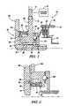
- FIG. 1is a cross-sectional elevational view of a portion of a torque-to-thrust apparatus incorporating the present invention.
- FIG. 2is another embodiment showing a torque-to-thrust apparatus employing the present invention.
- FIG. 3is yet another embodiment describing the torque-to-thrust apparatus employing the present invention.
- FIG. 4is a further embodiment of the present invention wherein a torque-to-thrust apparatus employs the present invention and wherein the torque-to-thrust apparatus includes a hydraulic mechanism.
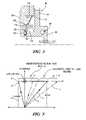
- FIG. 5is a series of curves relating motor torque to clamp load describing some of the operating characteristics of the present invention.
- FIG. 1a torque-to-thrust apparatus generally designated 10 .
- the torque-to-thrust apparatus 10has an electric motor 12 driving an input gear 14 , which meshes with an output gear 16 .
- a linearly moveable thrust plate 18is operatively connected to the gear 16 by a cam mechanism 20 , which includes a surface or track 22 formed on the output gear 16 and a surface or track 24 formed on the thrust plate 18 .
- the output gear 16has an inner diameter 26 , which is rotatably mounted on a surface 28 through a bearing 30 .
- the thrust plate 18is disposed in abutment with a spring 32 , which is contacting a friction plate 34 , that is a member of a friction torque-transmitting mechanism 36 .
- the friction torque-transmitting mechanism 36includes the friction plate 34 and friction plates 38 , which are interdigitated with friction plates 40 .
- the friction plates 34 and 38are splined to a housing 42
- the friction plates 40are splined to a housing 44 .
- the friction plates 34 , 38 , and 40as well as housings 42 and 44 , form a conventional friction operated torque-transmitting mechanism.
- the torque-to-thrust apparatus 10provides the apply force, which creates the frictional engagement between the plates 34 , 38 , and 40 .
- the output gear 16has a cylindrical portion 46 , which forms an inner race for a one-way mechanism or Mechanical Diode 48 .
- the one-way mechanism 48has an outer race 50 and a plurality of roller, sprag, or strut members 52 disposed between the inner race 46 and the outer race 50 .
- a thrust bearing 54is disposed between a radial face 56 of the output gear 16 .
- the thrust bearing 54is an antifriction bearing, which creates very little resistance to relative rotation between the face 56 and the outer race 50 .
- a friction plate 58is disposed between the outer race 50 and a stationary wall 60 .
- the friction plate 58when abutted by the outer race 50 will restrain or inhibit rotation of the outer race 50 .
- the inner race 46will be free to rotate in one direction while retarded in rotation in the other direction.
- the torque-transmitting mechanism 36When the electric motor 12 provides forward rotation for the gears 14 and 16 , the torque-transmitting mechanism 36 will be engaged by linear movement of the thrust plate 18 . The thrust force at the plate 18 will be reacted through the gear 16 to the outer race 50 thereby enforcing engagement between the outer race 50 and the friction plate 58 . Once the torque-transmitting mechanism 36 is fully engaged, the electric motor 12 can be de-energized.
- the frictional characteristics between the outer race 50 and the friction plate 58are such that the electric motor 12 upon reverse rotation can overcome this friction force thereby driving the gear 16 in the opposite direction to permit disengagement of the torque-transmitting mechanism 36 .
- the thrust force of the interface of the tracks 22 and 24reduces accordingly, thereby reducing the amount of energy required at the electric motor 12 . This force transfer can be seen in FIG. 5 .
- the dashed line Awould represent both the on-coming motor torque needed and the off-going motor torque needed to provide the clamping force or clamping load shown on the vertical axis.
- the on-coming motor torquemust pass or traverse along the line B, which, of course, requires a greater motor torque than the ideal situation.
- a motor torque along line Cwould be required in a conventional torque-to-thrust condition.
- the torque-to-thrust apparatuscan disengage unless a force is maintained at the motor. While sufficient friction can be built into the system, it greatly increases the motor torque.
- the line Drepresents the motor torque required to provide sufficient friction such that the release load for the motor torque follows the line E. Thus, a considerable amount of energy represented by the distance F is required to provide the locking feature.
- the on-coming motor torqueincreases along line B, which is required by the friction and the clamp load within the system, and having reached the desired clamp load and the friction mechanism comprised of the outer race 50 and the friction plate 58 is engaged by reversal of direction of rotation.
- the motor 12can be de-energized.
- the one-way mechanism 48 and the friction mechanismis released by energizing the motor 12 , in the opposite direction, when it is desired to relieve the thrust load of the torque to thrust apparatus 10 .
- Thiswill require a motor torque to be increased to the point G prior to the release load being present at the torque-to-thrust apparatus 10 .
- the torque-to-thrust apparatusis applied with the conventional motor torque and is released by a reversal of motor torque, which is great enough to overcome the friction plate 58 .
- the motor 12does not have to be energized to hold the torque to thrust apparatus 10 in the actuated condition.
- FIG. 2describes an alternative embodiment wherein rotation of the gear member 16 A is operable to provide a thrust force at thrust plate 18 A in a manner similar to that described in FIG. 1 .
- the gear 16 Ahas a cylindrical surface 80 , which forms the outer race of a one-way device or Mechanical Diode 82 .
- the inner race of the one-way device 82is a cylindrical component 84 .
- the one-way device 82has a plurality of rollers, sprags, or struts 86 disposed between the outer race 80 and the inner race 84 .
- the inner race 84is aligned axially to abut a friction plate 88 , which is held stationary by a housing 90 .
- the friction plate 88does not increase the required load of the input to the gear 16 A because the one-way device 82 is permitted to overrun, thereby bypassing the inner race 84 frictional engagement with the friction plate 88 via free rotation across thrust bearing 89 .
- the friction plate 88is engaged such that at full engagement of an associated torque-transmitting mechanism, the friction force at the inner race 84 will maintain the gear 16 A stationary until an input force from the electric motor is present to cause disengagement.
- a torque-to-thrust in one-way mechanism 92is shown in FIG. 3 .
- a gear member 94is operable in combination with a thrust plate 96 and a cam mechanism 98 to provide a thrust force to engage a conventional friction, operated torque-transmitting mechanism.
- the gear member 94has a cylindrical surface 100 forming the inner race of a one-way torque-transmitting mechanism or Mechanical Diode 102 .
- a cylindrical body 104forms the outer race of the torque-transmitting mechanism 102 .
- a thrust bearing 106provides an antifriction member between the gear member 94 and a stationary housing 108 .
- a Bellville or washer type spring 110is disposed between a locating ring 112 secured to the housing 108 and a locating ring 114 secured to the outer race 104 .
- the spring 110urges the outer race 104 leftward into engagement with a friction member or plate 116 .
- the spring 110therefore supplies the axial force required to engage the friction plate 116 . This would provide a constant force at the friction interface between the outer race 104 and the friction plate 116 .
- a torque-to-thrust apparatus 200is shown in FIG. 4 .
- This mechanismincludes an electric motor 202 having a stator 204 and a rotor 206 .
- the rotor 206drives a sleeve shaft 208 , which has formed thereon a roller screw 210 .
- the roller screw 210drives an output member 212 in a linear direction relative to the rotation of the rotor 206 .
- the member 212includes a master cylinder 213 having a piston 214 slidably disposed in a cylinder 216 .
- the cylinder 216is in fluid communication with a reservoir 218 through a passage 220 and with an output or outlet port 222 through a passage 224 .
- the passage 220When the piston 214 is fully retracted, as shown in FIG. 4 , the passage 220 is maintained open. When the piston 214 is driven rightwardly in the cylinder 216 , the passage 220 is closed and fluid within the cylinder 216 is driven or pumped through the outlet port 222 to a passage 226 , which is communicated with a chamber 228 disposed adjacent a slave cylinder 230 . The slave cylinder 230 moves axially to engage an apply spring 232 , which is a member of a conventional friction actuated torque-transmitting mechanism 234 .
- the pressure generated within the chamber 216 to provide engagement of the torque-transmitting mechanism 234is reacted through a thrust bearing 236 and a sleeve 238 to a friction plate 240 .
- the friction plate 240is connected to a stationary wall 242 through a sleeve 244 .
- the sleeve 238is rotatably supported through a one-way device or Mechanical Diode 245 to a housing 246 , which is rotatable with the rotor 206 .
- the one-way device 245permits substantially uninhibited relative rotation between the sleeve 238 and housing 246 when the rotor 206 is rotated in a direction to cause pumping between the piston 214 and the cylinder 216 .
- the electric motor 202can be de-energized and the fluid pressure within the slave cylinder 230 is maintained by the torsional friction load at friction plate 240 , which prevents reverse rotation of the motor 202 and thus prevents movement of the master cylinder 213 in the release direction.
Landscapes
- Engineering & Computer Science (AREA)
- General Engineering & Computer Science (AREA)
- Physics & Mathematics (AREA)
- Mechanical Engineering (AREA)
- Fluid Mechanics (AREA)
- Electromagnetism (AREA)
- Mechanical Operated Clutches (AREA)
- Braking Arrangements (AREA)
Abstract
Description
Claims (7)
Priority Applications (2)
| Application Number | Priority Date | Filing Date | Title |
|---|---|---|---|
| US10/801,790US7021442B2 (en) | 2004-03-16 | 2004-03-16 | One-way torque transmitter with a friction actuating apparatus |
| DE102005011142.4ADE102005011142B4 (en) | 2004-03-16 | 2005-03-10 | Torque / thrust conversion device with a freewheel torque transmission mechanism |
Applications Claiming Priority (1)
| Application Number | Priority Date | Filing Date | Title |
|---|---|---|---|
| US10/801,790US7021442B2 (en) | 2004-03-16 | 2004-03-16 | One-way torque transmitter with a friction actuating apparatus |
Publications (2)
| Publication Number | Publication Date |
|---|---|
| US20050205377A1 US20050205377A1 (en) | 2005-09-22 |
| US7021442B2true US7021442B2 (en) | 2006-04-04 |
Family
ID=34983117
Family Applications (1)
| Application Number | Title | Priority Date | Filing Date |
|---|---|---|---|
| US10/801,790Expired - LifetimeUS7021442B2 (en) | 2004-03-16 | 2004-03-16 | One-way torque transmitter with a friction actuating apparatus |
Country Status (2)
| Country | Link |
|---|---|
| US (1) | US7021442B2 (en) |
| DE (1) | DE102005011142B4 (en) |
Cited By (27)
| Publication number | Priority date | Publication date | Assignee | Title |
|---|---|---|---|---|
| US20070155573A1 (en)* | 2005-12-20 | 2007-07-05 | Theodor Gassmann | Friction coupling with actuator and plate spring |
| DE102008042388A1 (en)* | 2008-09-26 | 2010-04-01 | Zf Friedrichshafen Ag | Coupling device for frictional connection of two rotating components, has coupling half for making or releasing frictional connection between two rotating components with two assembly elements |
| CN102734343A (en)* | 2011-04-07 | 2012-10-17 | Zf腓德烈斯哈芬股份公司 | Device for changing operational status of shifting element with two shifting element halves |
| US10316902B2 (en)* | 2017-03-21 | 2019-06-11 | Schaeffler Technologies AG & Co. KG | Split groove wedge clutch |
| US10551798B1 (en) | 2016-05-17 | 2020-02-04 | Apple Inc. | Rotatable crown for an electronic device |
| US10572053B2 (en) | 2016-07-25 | 2020-02-25 | Apple Inc. | Force-detecting input structure |
| US10599101B2 (en) | 2014-09-02 | 2020-03-24 | Apple Inc. | Wearable electronic device |
| US10613685B2 (en) | 2014-02-12 | 2020-04-07 | Apple Inc. | Rejection of false turns of rotary inputs for electronic devices |
| US10655988B2 (en) | 2015-03-05 | 2020-05-19 | Apple Inc. | Watch with rotatable optical encoder having a spindle defining an array of alternating regions extending along an axial direction parallel to the axis of a shaft |
| US10664074B2 (en) | 2017-06-19 | 2020-05-26 | Apple Inc. | Contact-sensitive crown for an electronic watch |
| US10732571B2 (en) | 2013-08-09 | 2020-08-04 | Apple Inc. | Tactile switch for an electronic device |
| US10845764B2 (en) | 2015-03-08 | 2020-11-24 | Apple Inc. | Compressible seal for rotatable and translatable input mechanisms |
| US10955937B2 (en) | 2016-07-15 | 2021-03-23 | Apple Inc. | Capacitive gap sensor ring for an input device |
| US10962935B1 (en) | 2017-07-18 | 2021-03-30 | Apple Inc. | Tri-axis force sensor |
| US11015960B2 (en) | 2014-07-16 | 2021-05-25 | Apple Inc. | Optical encoder for detecting crown movement |
| US11181863B2 (en) | 2018-08-24 | 2021-11-23 | Apple Inc. | Conductive cap for watch crown |
| US11194299B1 (en) | 2019-02-12 | 2021-12-07 | Apple Inc. | Variable frictional feedback device for a digital crown of an electronic watch |
| US11194298B2 (en) | 2018-08-30 | 2021-12-07 | Apple Inc. | Crown assembly for an electronic watch |
| US11360440B2 (en) | 2018-06-25 | 2022-06-14 | Apple Inc. | Crown for an electronic watch |
| US11531306B2 (en) | 2013-06-11 | 2022-12-20 | Apple Inc. | Rotary input mechanism for an electronic device |
| US11550268B2 (en) | 2020-06-02 | 2023-01-10 | Apple Inc. | Switch module for electronic crown assembly |
| US11561515B2 (en) | 2018-08-02 | 2023-01-24 | Apple Inc. | Crown for an electronic watch |
| US11796961B2 (en) | 2018-08-24 | 2023-10-24 | Apple Inc. | Conductive cap for watch crown |
| US11796968B2 (en) | 2018-08-30 | 2023-10-24 | Apple Inc. | Crown assembly for an electronic watch |
| US12092996B2 (en) | 2021-07-16 | 2024-09-17 | Apple Inc. | Laser-based rotation sensor for a crown of an electronic watch |
| US12189347B2 (en) | 2022-06-14 | 2025-01-07 | Apple Inc. | Rotation sensor for a crown of an electronic watch |
| US12259690B2 (en) | 2018-08-24 | 2025-03-25 | Apple Inc. | Watch crown having a conductive surface |
Families Citing this family (19)
| Publication number | Priority date | Publication date | Assignee | Title |
|---|---|---|---|---|
| US7086976B2 (en)* | 2004-04-07 | 2006-08-08 | General Motors Corporation | Electric motor applied clutch with a drag torque actuator |
| US7036644B2 (en)* | 2004-05-21 | 2006-05-02 | General Motors Corporation | Torque-transmitting mechanism with latching apparatus |
| DE102006001621A1 (en)* | 2006-01-11 | 2007-07-19 | Voith Turbo Gmbh & Co. Kg | Adjustable free wheel clutch for use in motor vehicle, has two individual brake devices acting in respective rotating directions and arranged in spatial distance to one another, where brake devices are individually controllable |
| DE102010047800A1 (en)* | 2009-10-29 | 2011-05-05 | Schaeffler Technologies Gmbh & Co. Kg | Hydrostatic clutch actuator |
| JP5998571B2 (en)* | 2012-03-28 | 2016-09-28 | 株式会社ジェイテクト | Driving force transmission device and four-wheel drive vehicle equipped with the same |
| DE112014005561A5 (en)* | 2013-12-06 | 2016-08-25 | Schaeffler Technologies AG & Co. KG | Actuator with planetary roller screw (PWG) |
| US9327598B1 (en) | 2014-11-05 | 2016-05-03 | GM Global Technology Operations LLC | Multi-speed transmission with mechanical on-off clutch |
| US9891651B2 (en)* | 2016-02-27 | 2018-02-13 | Apple Inc. | Rotatable input mechanism having adjustable output |
| EP3908765B1 (en)* | 2019-01-11 | 2024-10-23 | GKN Automotive Limited | Actuator assembly for a clutch assembly for the powertrain of a motor vehicle |
| WO2021020314A1 (en)* | 2019-07-26 | 2021-02-04 | 株式会社デンソー | Clutch device |
| CN114144594A (en)* | 2019-07-26 | 2022-03-04 | 株式会社电装 | clutch device |
| CN114144596A (en)* | 2019-07-26 | 2022-03-04 | 株式会社电装 | clutch device |
| CN114144595A (en)* | 2019-07-26 | 2022-03-04 | 株式会社电装 | Clutch device |
| CN114144597A (en)* | 2019-07-26 | 2022-03-04 | 株式会社电装 | Clutch device |
| WO2021020315A1 (en)* | 2019-07-26 | 2021-02-04 | 株式会社デンソー | Clutch device |
| JP7272216B2 (en)* | 2019-07-26 | 2023-05-12 | 株式会社デンソー | clutch device |
| WO2021020318A1 (en)* | 2019-07-26 | 2021-02-04 | 株式会社デンソー | Clutch device |
| WO2022118850A1 (en)* | 2020-12-03 | 2022-06-09 | 株式会社デンソー | Clutch actuator |
| DE112022003314T5 (en)* | 2021-06-30 | 2024-04-18 | Denso Corporation | Clutch actuator |
Citations (8)
| Publication number | Priority date | Publication date | Assignee | Title |
|---|---|---|---|---|
| US5651437A (en)* | 1996-04-17 | 1997-07-29 | Eaton Corporation | Clutch ball ramp actuator to maintain state upon loss of power |
| US5810141A (en)* | 1996-12-13 | 1998-09-22 | Eaton Corporation | Driveline clutch with unidirectional apply ball ramp |
| US5910061A (en)* | 1997-09-30 | 1999-06-08 | Eaton Corporation | Ball ramp driveline clutch actuator with unidirectional apply |
| USRE36502E (en)* | 1994-01-31 | 2000-01-18 | Eaton Corporation | Clutch ball ramp actuator with drive and coast apply |
| US6032776A (en)* | 1997-09-12 | 2000-03-07 | Aichi Kikai Kogyo Kabushiki Kaisha | Automatic operating apparatus for a friction clutch |
| US6742642B1 (en)* | 2002-11-25 | 2004-06-01 | General Motors Corporation | Torque-transmitting torque to thrust apply mechanism having amplified thrust |
| US6874609B2 (en)* | 2002-11-25 | 2005-04-05 | General Motors Corporation | Rotary-to-linear transfer device |
| US6948396B2 (en)* | 2003-12-17 | 2005-09-27 | General Motors Corporation | Control apparatus for a multi-speed transmission |
Family Cites Families (1)
| Publication number | Priority date | Publication date | Assignee | Title |
|---|---|---|---|---|
| US20040112792A1 (en)* | 1998-02-13 | 2004-06-17 | Murphy William J. | Method for making lube basestocks |
- 2004
- 2004-03-16USUS10/801,790patent/US7021442B2/ennot_activeExpired - Lifetime
- 2005
- 2005-03-10DEDE102005011142.4Apatent/DE102005011142B4/ennot_activeExpired - Lifetime
Patent Citations (8)
| Publication number | Priority date | Publication date | Assignee | Title |
|---|---|---|---|---|
| USRE36502E (en)* | 1994-01-31 | 2000-01-18 | Eaton Corporation | Clutch ball ramp actuator with drive and coast apply |
| US5651437A (en)* | 1996-04-17 | 1997-07-29 | Eaton Corporation | Clutch ball ramp actuator to maintain state upon loss of power |
| US5810141A (en)* | 1996-12-13 | 1998-09-22 | Eaton Corporation | Driveline clutch with unidirectional apply ball ramp |
| US6032776A (en)* | 1997-09-12 | 2000-03-07 | Aichi Kikai Kogyo Kabushiki Kaisha | Automatic operating apparatus for a friction clutch |
| US5910061A (en)* | 1997-09-30 | 1999-06-08 | Eaton Corporation | Ball ramp driveline clutch actuator with unidirectional apply |
| US6742642B1 (en)* | 2002-11-25 | 2004-06-01 | General Motors Corporation | Torque-transmitting torque to thrust apply mechanism having amplified thrust |
| US6874609B2 (en)* | 2002-11-25 | 2005-04-05 | General Motors Corporation | Rotary-to-linear transfer device |
| US6948396B2 (en)* | 2003-12-17 | 2005-09-27 | General Motors Corporation | Control apparatus for a multi-speed transmission |
Cited By (66)
| Publication number | Priority date | Publication date | Assignee | Title |
|---|---|---|---|---|
| US20070155573A1 (en)* | 2005-12-20 | 2007-07-05 | Theodor Gassmann | Friction coupling with actuator and plate spring |
| US7699740B2 (en)* | 2005-12-20 | 2010-04-20 | Gkn Driveline International Gmbh | Friction coupling with actuator and plate spring |
| US20100222175A1 (en)* | 2005-12-20 | 2010-09-02 | Theodor Gassmann | Friction coupling with actuator and a ball bearing |
| US7993233B2 (en) | 2005-12-20 | 2011-08-09 | Gkn Driveline International, Gmbh | Friction coupling with actuator and a ball bearing |
| DE102008042388A1 (en)* | 2008-09-26 | 2010-04-01 | Zf Friedrichshafen Ag | Coupling device for frictional connection of two rotating components, has coupling half for making or releasing frictional connection between two rotating components with two assembly elements |
| CN102734343A (en)* | 2011-04-07 | 2012-10-17 | Zf腓德烈斯哈芬股份公司 | Device for changing operational status of shifting element with two shifting element halves |
| US11531306B2 (en) | 2013-06-11 | 2022-12-20 | Apple Inc. | Rotary input mechanism for an electronic device |
| US12181840B2 (en) | 2013-08-09 | 2024-12-31 | Apple Inc. | Tactile switch for an electronic device |
| US10962930B2 (en) | 2013-08-09 | 2021-03-30 | Apple Inc. | Tactile switch for an electronic device |
| US11886149B2 (en) | 2013-08-09 | 2024-01-30 | Apple Inc. | Tactile switch for an electronic device |
| US10732571B2 (en) | 2013-08-09 | 2020-08-04 | Apple Inc. | Tactile switch for an electronic device |
| US11669205B2 (en) | 2014-02-12 | 2023-06-06 | Apple Inc. | Rejection of false turns of rotary inputs for electronic devices |
| US10884549B2 (en) | 2014-02-12 | 2021-01-05 | Apple Inc. | Rejection of false turns of rotary inputs for electronic devices |
| US11347351B2 (en) | 2014-02-12 | 2022-05-31 | Apple Inc. | Rejection of false turns of rotary inputs for electronic devices |
| US12307047B2 (en) | 2014-02-12 | 2025-05-20 | Apple Inc. | Rejection of false turns of rotary inputs for electronic devices |
| US10613685B2 (en) | 2014-02-12 | 2020-04-07 | Apple Inc. | Rejection of false turns of rotary inputs for electronic devices |
| US12045416B2 (en) | 2014-02-12 | 2024-07-23 | Apple Inc. | Rejection of false turns of rotary inputs for electronic devices |
| US11015960B2 (en) | 2014-07-16 | 2021-05-25 | Apple Inc. | Optical encoder for detecting crown movement |
| US11762342B2 (en) | 2014-09-02 | 2023-09-19 | Apple Inc. | Wearable electronic device |
| US10942491B2 (en) | 2014-09-02 | 2021-03-09 | Apple Inc. | Wearable electronic device |
| US10620591B2 (en) | 2014-09-02 | 2020-04-14 | Apple Inc. | Wearable electronic device |
| US11221590B2 (en) | 2014-09-02 | 2022-01-11 | Apple Inc. | Wearable electronic device |
| US11567457B2 (en) | 2014-09-02 | 2023-01-31 | Apple Inc. | Wearable electronic device |
| US10599101B2 (en) | 2014-09-02 | 2020-03-24 | Apple Inc. | Wearable electronic device |
| US10613485B2 (en) | 2014-09-02 | 2020-04-07 | Apple Inc. | Wearable electronic device |
| US11474483B2 (en) | 2014-09-02 | 2022-10-18 | Apple Inc. | Wearable electronic device |
| US10627783B2 (en) | 2014-09-02 | 2020-04-21 | Apple Inc. | Wearable electronic device |
| US11002572B2 (en) | 2015-03-05 | 2021-05-11 | Apple Inc. | Optical encoder with direction-dependent optical properties comprising a spindle having an array of surface features defining a concave contour along a first direction and a convex contour along a second direction |
| US10655988B2 (en) | 2015-03-05 | 2020-05-19 | Apple Inc. | Watch with rotatable optical encoder having a spindle defining an array of alternating regions extending along an axial direction parallel to the axis of a shaft |
| US11988995B2 (en) | 2015-03-08 | 2024-05-21 | Apple Inc. | Compressible seal for rotatable and translatable input mechanisms |
| US10845764B2 (en) | 2015-03-08 | 2020-11-24 | Apple Inc. | Compressible seal for rotatable and translatable input mechanisms |
| US10551798B1 (en) | 2016-05-17 | 2020-02-04 | Apple Inc. | Rotatable crown for an electronic device |
| US12104929B2 (en) | 2016-05-17 | 2024-10-01 | Apple Inc. | Rotatable crown for an electronic device |
| US10955937B2 (en) | 2016-07-15 | 2021-03-23 | Apple Inc. | Capacitive gap sensor ring for an input device |
| US11513613B2 (en) | 2016-07-15 | 2022-11-29 | Apple Inc. | Capacitive gap sensor ring for an input device |
| US12086331B2 (en) | 2016-07-15 | 2024-09-10 | Apple Inc. | Capacitive gap sensor ring for an input device |
| US10572053B2 (en) | 2016-07-25 | 2020-02-25 | Apple Inc. | Force-detecting input structure |
| US10948880B2 (en) | 2016-07-25 | 2021-03-16 | Apple Inc. | Force-detecting input structure |
| US11385599B2 (en) | 2016-07-25 | 2022-07-12 | Apple Inc. | Force-detecting input structure |
| US11720064B2 (en) | 2016-07-25 | 2023-08-08 | Apple Inc. | Force-detecting input structure |
| US12105479B2 (en) | 2016-07-25 | 2024-10-01 | Apple Inc. | Force-detecting input structure |
| US10316902B2 (en)* | 2017-03-21 | 2019-06-11 | Schaeffler Technologies AG & Co. KG | Split groove wedge clutch |
| US10664074B2 (en) | 2017-06-19 | 2020-05-26 | Apple Inc. | Contact-sensitive crown for an electronic watch |
| US12066795B2 (en) | 2017-07-18 | 2024-08-20 | Apple Inc. | Tri-axis force sensor |
| US10962935B1 (en) | 2017-07-18 | 2021-03-30 | Apple Inc. | Tri-axis force sensor |
| US11360440B2 (en) | 2018-06-25 | 2022-06-14 | Apple Inc. | Crown for an electronic watch |
| US11754981B2 (en) | 2018-06-25 | 2023-09-12 | Apple Inc. | Crown for an electronic watch |
| US12105480B2 (en) | 2018-06-25 | 2024-10-01 | Apple Inc. | Crown for an electronic watch |
| US12282302B2 (en) | 2018-08-02 | 2025-04-22 | Apple Inc. | Crown for an electronic watch |
| US11906937B2 (en) | 2018-08-02 | 2024-02-20 | Apple Inc. | Crown for an electronic watch |
| US11561515B2 (en) | 2018-08-02 | 2023-01-24 | Apple Inc. | Crown for an electronic watch |
| US11181863B2 (en) | 2018-08-24 | 2021-11-23 | Apple Inc. | Conductive cap for watch crown |
| US12259690B2 (en) | 2018-08-24 | 2025-03-25 | Apple Inc. | Watch crown having a conductive surface |
| US11796961B2 (en) | 2018-08-24 | 2023-10-24 | Apple Inc. | Conductive cap for watch crown |
| US12276943B2 (en) | 2018-08-24 | 2025-04-15 | Apple Inc. | Conductive cap for watch crown |
| US11796968B2 (en) | 2018-08-30 | 2023-10-24 | Apple Inc. | Crown assembly for an electronic watch |
| US11194298B2 (en) | 2018-08-30 | 2021-12-07 | Apple Inc. | Crown assembly for an electronic watch |
| US12326697B2 (en) | 2018-08-30 | 2025-06-10 | Apple Inc. | Crown assembly for an electronic watch |
| US11860587B2 (en) | 2019-02-12 | 2024-01-02 | Apple Inc. | Variable frictional feedback device for a digital crown of an electronic watch |
| US11194299B1 (en) | 2019-02-12 | 2021-12-07 | Apple Inc. | Variable frictional feedback device for a digital crown of an electronic watch |
| US12346070B2 (en) | 2019-02-12 | 2025-07-01 | Apple Inc. | Variable frictional feedback device for a digital crown of an electronic watch |
| US11815860B2 (en) | 2020-06-02 | 2023-11-14 | Apple Inc. | Switch module for electronic crown assembly |
| US12189342B2 (en) | 2020-06-02 | 2025-01-07 | Apple Inc. | Switch module for electronic crown assembly |
| US11550268B2 (en) | 2020-06-02 | 2023-01-10 | Apple Inc. | Switch module for electronic crown assembly |
| US12092996B2 (en) | 2021-07-16 | 2024-09-17 | Apple Inc. | Laser-based rotation sensor for a crown of an electronic watch |
| US12189347B2 (en) | 2022-06-14 | 2025-01-07 | Apple Inc. | Rotation sensor for a crown of an electronic watch |
Also Published As
| Publication number | Publication date |
|---|---|
| DE102005011142B4 (en) | 2016-01-07 |
| US20050205377A1 (en) | 2005-09-22 |
| DE102005011142A1 (en) | 2005-10-13 |
Similar Documents
| Publication | Publication Date | Title |
|---|---|---|
| US7021442B2 (en) | One-way torque transmitter with a friction actuating apparatus | |
| US8079453B2 (en) | Controllable overrunning coupling assembly | |
| US6814201B2 (en) | Bi-directional axially applied pawl clutch assembly | |
| US8286772B2 (en) | Controllable coupling assembly and overrunning coupling and control assembly utilizing same | |
| US8267231B2 (en) | Electrically variable transmission with an axially-moveable selectable one-way clutch assembly | |
| US8397890B2 (en) | Latching clutch assembly and method of operating the same | |
| US8074778B2 (en) | Clutch and brake latch mechanism | |
| US8051959B2 (en) | Controllable or selectable bi-directional overrunning coupling assembly | |
| US7036644B2 (en) | Torque-transmitting mechanism with latching apparatus | |
| US3895700A (en) | Worm/worm-wheel overrunning clutch | |
| CA2022793A1 (en) | Ball screw actuated clutch combination | |
| US4128145A (en) | Combination failsafe brake and one-way clutch | |
| US9933024B2 (en) | Variable two-way over-running clutch | |
| US3722641A (en) | No back actuator system | |
| US6742642B1 (en) | Torque-transmitting torque to thrust apply mechanism having amplified thrust | |
| US8469855B2 (en) | Two-speed transmission module with passive automatic shifting | |
| US3324981A (en) | Combined cone and plate type clutch mechanism | |
| US6066065A (en) | Compounder assembly for automatic transmission | |
| US2461217A (en) | One-way brake for torque converters | |
| US2257987A (en) | Clutch construction | |
| US2449020A (en) | Power drive | |
| CN114198426B (en) | Position locking type high-speed synchronous automatic clutch | |
| US6206161B1 (en) | Selectively engageable torque transmitting mechanism with a one-way screw apply | |
| US6745880B1 (en) | Two-way clutch assembly having selective actuation | |
| US3509974A (en) | Internal resistance roller clutch |
Legal Events
| Date | Code | Title | Description |
|---|---|---|---|
| AS | Assignment | Owner name:GENERAL MOTORS CORPORATION, MICHIGAN Free format text:ASSIGNMENT OF ASSIGNORS INTEREST;ASSIGNORS:BORGERSON, JAMES B.;STEVENSON, PAUL D.;REEL/FRAME:014778/0559 Effective date:20040206 | |
| STCF | Information on status: patent grant | Free format text:PATENTED CASE | |
| AS | Assignment | Owner name:GM GLOBAL TECHNOLOGY OPERATIONS, INC., MICHIGAN Free format text:ASSIGNMENT OF ASSIGNORS INTEREST;ASSIGNOR:GENERAL MOTORS CORPORATION;REEL/FRAME:022117/0022 Effective date:20050119 Owner name:GM GLOBAL TECHNOLOGY OPERATIONS, INC.,MICHIGAN Free format text:ASSIGNMENT OF ASSIGNORS INTEREST;ASSIGNOR:GENERAL MOTORS CORPORATION;REEL/FRAME:022117/0022 Effective date:20050119 | |
| AS | Assignment | Owner name:UNITED STATES DEPARTMENT OF THE TREASURY, DISTRICT Free format text:SECURITY AGREEMENT;ASSIGNOR:GM GLOBAL TECHNOLOGY OPERATIONS, INC.;REEL/FRAME:022201/0610 Effective date:20081231 Owner name:UNITED STATES DEPARTMENT OF THE TREASURY,DISTRICT Free format text:SECURITY AGREEMENT;ASSIGNOR:GM GLOBAL TECHNOLOGY OPERATIONS, INC.;REEL/FRAME:022201/0610 Effective date:20081231 | |
| AS | Assignment | Owner name:CITICORP USA, INC. AS AGENT FOR BANK PRIORITY SECU Free format text:SECURITY AGREEMENT;ASSIGNOR:GM GLOBAL TECHNOLOGY OPERATIONS, INC.;REEL/FRAME:022553/0446 Effective date:20090409 Owner name:CITICORP USA, INC. AS AGENT FOR HEDGE PRIORITY SEC Free format text:SECURITY AGREEMENT;ASSIGNOR:GM GLOBAL TECHNOLOGY OPERATIONS, INC.;REEL/FRAME:022553/0446 Effective date:20090409 | |
| AS | Assignment | Owner name:GM GLOBAL TECHNOLOGY OPERATIONS, INC., MICHIGAN Free format text:RELEASE BY SECURED PARTY;ASSIGNOR:UNITED STATES DEPARTMENT OF THE TREASURY;REEL/FRAME:023124/0429 Effective date:20090709 Owner name:GM GLOBAL TECHNOLOGY OPERATIONS, INC.,MICHIGAN Free format text:RELEASE BY SECURED PARTY;ASSIGNOR:UNITED STATES DEPARTMENT OF THE TREASURY;REEL/FRAME:023124/0429 Effective date:20090709 | |
| AS | Assignment | Owner name:GM GLOBAL TECHNOLOGY OPERATIONS, INC., MICHIGAN Free format text:RELEASE BY SECURED PARTY;ASSIGNORS:CITICORP USA, INC. AS AGENT FOR BANK PRIORITY SECURED PARTIES;CITICORP USA, INC. AS AGENT FOR HEDGE PRIORITY SECURED PARTIES;REEL/FRAME:023127/0468 Effective date:20090814 Owner name:GM GLOBAL TECHNOLOGY OPERATIONS, INC.,MICHIGAN Free format text:RELEASE BY SECURED PARTY;ASSIGNORS:CITICORP USA, INC. AS AGENT FOR BANK PRIORITY SECURED PARTIES;CITICORP USA, INC. AS AGENT FOR HEDGE PRIORITY SECURED PARTIES;REEL/FRAME:023127/0468 Effective date:20090814 | |
| AS | Assignment | Owner name:UNITED STATES DEPARTMENT OF THE TREASURY, DISTRICT Free format text:SECURITY AGREEMENT;ASSIGNOR:GM GLOBAL TECHNOLOGY OPERATIONS, INC.;REEL/FRAME:023156/0052 Effective date:20090710 Owner name:UNITED STATES DEPARTMENT OF THE TREASURY,DISTRICT Free format text:SECURITY AGREEMENT;ASSIGNOR:GM GLOBAL TECHNOLOGY OPERATIONS, INC.;REEL/FRAME:023156/0052 Effective date:20090710 | |
| AS | Assignment | Owner name:UAW RETIREE MEDICAL BENEFITS TRUST, MICHIGAN Free format text:SECURITY AGREEMENT;ASSIGNOR:GM GLOBAL TECHNOLOGY OPERATIONS, INC.;REEL/FRAME:023162/0001 Effective date:20090710 Owner name:UAW RETIREE MEDICAL BENEFITS TRUST,MICHIGAN Free format text:SECURITY AGREEMENT;ASSIGNOR:GM GLOBAL TECHNOLOGY OPERATIONS, INC.;REEL/FRAME:023162/0001 Effective date:20090710 | |
| FPAY | Fee payment | Year of fee payment:4 | |
| AS | Assignment | Owner name:GM GLOBAL TECHNOLOGY OPERATIONS, INC., MICHIGAN Free format text:RELEASE BY SECURED PARTY;ASSIGNOR:UAW RETIREE MEDICAL BENEFITS TRUST;REEL/FRAME:025311/0770 Effective date:20101026 Owner name:GM GLOBAL TECHNOLOGY OPERATIONS, INC., MICHIGAN Free format text:RELEASE BY SECURED PARTY;ASSIGNOR:UNITED STATES DEPARTMENT OF THE TREASURY;REEL/FRAME:025245/0442 Effective date:20100420 | |
| AS | Assignment | Owner name:WILMINGTON TRUST COMPANY, DELAWARE Free format text:SECURITY AGREEMENT;ASSIGNOR:GM GLOBAL TECHNOLOGY OPERATIONS, INC.;REEL/FRAME:025327/0262 Effective date:20101027 | |
| AS | Assignment | Owner name:GM GLOBAL TECHNOLOGY OPERATIONS LLC, MICHIGAN Free format text:CHANGE OF NAME;ASSIGNOR:GM GLOBAL TECHNOLOGY OPERATIONS, INC.;REEL/FRAME:025780/0902 Effective date:20101202 | |
| FPAY | Fee payment | Year of fee payment:8 | |
| AS | Assignment | Owner name:GM GLOBAL TECHNOLOGY OPERATIONS LLC, MICHIGAN Free format text:RELEASE BY SECURED PARTY;ASSIGNOR:WILMINGTON TRUST COMPANY;REEL/FRAME:034371/0676 Effective date:20141017 | |
| MAFP | Maintenance fee payment | Free format text:PAYMENT OF MAINTENANCE FEE, 12TH YEAR, LARGE ENTITY (ORIGINAL EVENT CODE: M1553) Year of fee payment:12 |