US7021416B2 - Vehicle control with manual back up - Google Patents
Vehicle control with manual back upDownload PDFInfo
- Publication number
- US7021416B2 US7021416B2US10/240,116US24011602AUS7021416B2US 7021416 B2US7021416 B2US 7021416B2US 24011602 AUS24011602 AUS 24011602AUS 7021416 B2US7021416 B2US 7021416B2
- Authority
- US
- United States
- Prior art keywords
- gear wheel
- control means
- vehicle
- joystick
- means according
- Prior art date
- Legal status (The legal status is an assumption and is not a legal conclusion. Google has not performed a legal analysis and makes no representation as to the accuracy of the status listed.)
- Expired - Fee Related, expires
Links
- 230000033001locomotionEffects0.000claimsabstractdescription6
- 230000001133accelerationEffects0.000claimsabstractdescription3
- 230000008878couplingEffects0.000claimsdescription6
- 238000010168coupling processMethods0.000claimsdescription6
- 238000005859coupling reactionMethods0.000claimsdescription6
- 230000009467reductionEffects0.000claimsdescription4
- 238000012423maintenanceMethods0.000abstractdescription4
- 238000006073displacement reactionMethods0.000description3
- 230000007246mechanismEffects0.000description2
- 230000009471actionEffects0.000description1
- 230000005540biological transmissionEffects0.000description1
- 238000011161developmentMethods0.000description1
- 230000018109developmental processEffects0.000description1
- 230000001771impaired effectEffects0.000description1
Images


Classifications
- G—PHYSICS
- G05—CONTROLLING; REGULATING
- G05G—CONTROL DEVICES OR SYSTEMS INSOFAR AS CHARACTERISED BY MECHANICAL FEATURES ONLY
- G05G9/00—Manually-actuated control mechanisms provided with one single controlling member co-operating with two or more controlled members, e.g. selectively, simultaneously
- G05G9/02—Manually-actuated control mechanisms provided with one single controlling member co-operating with two or more controlled members, e.g. selectively, simultaneously the controlling member being movable in different independent ways, movement in each individual way actuating one controlled member only
- G05G9/04—Manually-actuated control mechanisms provided with one single controlling member co-operating with two or more controlled members, e.g. selectively, simultaneously the controlling member being movable in different independent ways, movement in each individual way actuating one controlled member only in which movement in two or more ways can occur simultaneously
- G05G9/047—Manually-actuated control mechanisms provided with one single controlling member co-operating with two or more controlled members, e.g. selectively, simultaneously the controlling member being movable in different independent ways, movement in each individual way actuating one controlled member only in which movement in two or more ways can occur simultaneously the controlling member being movable by hand about orthogonal axes, e.g. joysticks
- B—PERFORMING OPERATIONS; TRANSPORTING
- B60—VEHICLES IN GENERAL
- B60W—CONJOINT CONTROL OF VEHICLE SUB-UNITS OF DIFFERENT TYPE OR DIFFERENT FUNCTION; CONTROL SYSTEMS SPECIALLY ADAPTED FOR HYBRID VEHICLES; ROAD VEHICLE DRIVE CONTROL SYSTEMS FOR PURPOSES NOT RELATED TO THE CONTROL OF A PARTICULAR SUB-UNIT
- B60W10/00—Conjoint control of vehicle sub-units of different type or different function
- B60W10/04—Conjoint control of vehicle sub-units of different type or different function including control of propulsion units
- B—PERFORMING OPERATIONS; TRANSPORTING
- B60—VEHICLES IN GENERAL
- B60W—CONJOINT CONTROL OF VEHICLE SUB-UNITS OF DIFFERENT TYPE OR DIFFERENT FUNCTION; CONTROL SYSTEMS SPECIALLY ADAPTED FOR HYBRID VEHICLES; ROAD VEHICLE DRIVE CONTROL SYSTEMS FOR PURPOSES NOT RELATED TO THE CONTROL OF A PARTICULAR SUB-UNIT
- B60W10/00—Conjoint control of vehicle sub-units of different type or different function
- B60W10/20—Conjoint control of vehicle sub-units of different type or different function including control of steering systems
- B—PERFORMING OPERATIONS; TRANSPORTING
- B60—VEHICLES IN GENERAL
- B60W—CONJOINT CONTROL OF VEHICLE SUB-UNITS OF DIFFERENT TYPE OR DIFFERENT FUNCTION; CONTROL SYSTEMS SPECIALLY ADAPTED FOR HYBRID VEHICLES; ROAD VEHICLE DRIVE CONTROL SYSTEMS FOR PURPOSES NOT RELATED TO THE CONTROL OF A PARTICULAR SUB-UNIT
- B60W30/00—Purposes of road vehicle drive control systems not related to the control of a particular sub-unit, e.g. of systems using conjoint control of vehicle sub-units
- B60W30/18—Propelling the vehicle
- B—PERFORMING OPERATIONS; TRANSPORTING
- B62—LAND VEHICLES FOR TRAVELLING OTHERWISE THAN ON RAILS
- B62D—MOTOR VEHICLES; TRAILERS
- B62D1/00—Steering controls, i.e. means for initiating a change of direction of the vehicle
- B62D1/02—Steering controls, i.e. means for initiating a change of direction of the vehicle vehicle-mounted
- B62D1/16—Steering columns
- B62D1/163—Part of the steering column replaced by flexible means, e.g. cable or belt
- B—PERFORMING OPERATIONS; TRANSPORTING
- B62—LAND VEHICLES FOR TRAVELLING OTHERWISE THAN ON RAILS
- B62D—MOTOR VEHICLES; TRAILERS
- B62D5/00—Power-assisted or power-driven steering
- B62D5/001—Mechanical components or aspects of steer-by-wire systems, not otherwise provided for in this maingroup
- B62D5/003—Backup systems, e.g. for manual steering
- B—PERFORMING OPERATIONS; TRANSPORTING
- B62—LAND VEHICLES FOR TRAVELLING OTHERWISE THAN ON RAILS
- B62D—MOTOR VEHICLES; TRAILERS
- B62D5/00—Power-assisted or power-driven steering
- B62D5/04—Power-assisted or power-driven steering electrical, e.g. using an electric servo-motor connected to, or forming part of, the steering gear
- B62D5/0442—Conversion of rotational into longitudinal movement
- B62D5/0445—Screw drives
- B62D5/0448—Ball nuts
- B—PERFORMING OPERATIONS; TRANSPORTING
- B60—VEHICLES IN GENERAL
- B60W—CONJOINT CONTROL OF VEHICLE SUB-UNITS OF DIFFERENT TYPE OR DIFFERENT FUNCTION; CONTROL SYSTEMS SPECIALLY ADAPTED FOR HYBRID VEHICLES; ROAD VEHICLE DRIVE CONTROL SYSTEMS FOR PURPOSES NOT RELATED TO THE CONTROL OF A PARTICULAR SUB-UNIT
- B60W2710/00—Output or target parameters relating to a particular sub-units
- B60W2710/20—Steering systems
- B—PERFORMING OPERATIONS; TRANSPORTING
- B62—LAND VEHICLES FOR TRAVELLING OTHERWISE THAN ON RAILS
- B62D—MOTOR VEHICLES; TRAILERS
- B62D1/00—Steering controls, i.e. means for initiating a change of direction of the vehicle
- B62D1/02—Steering controls, i.e. means for initiating a change of direction of the vehicle vehicle-mounted
- Y—GENERAL TAGGING OF NEW TECHNOLOGICAL DEVELOPMENTS; GENERAL TAGGING OF CROSS-SECTIONAL TECHNOLOGIES SPANNING OVER SEVERAL SECTIONS OF THE IPC; TECHNICAL SUBJECTS COVERED BY FORMER USPC CROSS-REFERENCE ART COLLECTIONS [XRACs] AND DIGESTS
- Y10—TECHNICAL SUBJECTS COVERED BY FORMER USPC
- Y10T—TECHNICAL SUBJECTS COVERED BY FORMER US CLASSIFICATION
- Y10T74/00—Machine element or mechanism
- Y10T74/20—Control lever and linkage systems
- Y10T74/20207—Multiple controlling elements for single controlled element
- Y10T74/20256—Steering and controls assemblies
- Y—GENERAL TAGGING OF NEW TECHNOLOGICAL DEVELOPMENTS; GENERAL TAGGING OF CROSS-SECTIONAL TECHNOLOGIES SPANNING OVER SEVERAL SECTIONS OF THE IPC; TECHNICAL SUBJECTS COVERED BY FORMER USPC CROSS-REFERENCE ART COLLECTIONS [XRACs] AND DIGESTS
- Y10—TECHNICAL SUBJECTS COVERED BY FORMER USPC
- Y10T—TECHNICAL SUBJECTS COVERED BY FORMER US CLASSIFICATION
- Y10T74/00—Machine element or mechanism
- Y10T74/20—Control lever and linkage systems
- Y10T74/20396—Hand operated
Definitions
- the inventionis related to the field of manual control means for electrically driven steering and/or decelerating and/or accelerating of a road vehicle.
- Such control of vehiclesis becoming more important as a result of recent developments related to electromechanical actuators, e.g. screw actuators for driving the vehicle brakes, steering column, clutch etc.
- the object of the inventionis, therefore, to provide a manual control means which is specifically adapted to the electric character of recent steering, braking, and accelerating devices etc., and which also can ensure the required safety level.
- a manual control meansfor the electrically driven and controlled steering, and/or accelerating and/or decelerating of a road vehicle, comprising: a hand grip means; sensors for sensing a force and/or a movement imposed on the hand grip means which correspond to a desired steering direction, and/or acceleration and/or deceleration of the vehicle; and manual lever means comprising at least one mechanical connection for mechanically steering, and/or accelerating, and/or decelerating of the vehicle in the absence of electric power, such as in the case of an electric power failure or in the case of electric power switched off, maintenance, garage parking etc., where the manual lever means being rotatable about at least one axis for actuating said at least one mechanical connection.
- the manual control meanscomprises first of all a hand grip means which is influenced by the human hand so as to provide the desired steering, and/or decelerating and/or accelerating signals. These signals can be conveyed to the respective electromechanical actuator devices through electric cables, which enables a flexible routing. Additionally, the manual control means comprise a mechanical back-up device for each function, which makes it possible to achieve a safe conduct of the vehicle in the case of a power interruption. For example, the manual control means can achieve a safe conduct of the vehicle in an emergency situation, but the mechanical back-up system can also be used in other circumstances, e.g. during maintenance, garage parking, etc.
- the control forces to be exerted on the hand grip meansshould remain limited for the driver so as to maintain control over the vehicle.
- the hand grip meansis at one end of the manual lever means, the other end of said manual lever means being swivelable about at least one axis and comprising a mechanical connection which provides a displacement and/or a rotation upon swiveling the manual lever means about said axis.
- the manual lever meansis swivelable about two non parallel axes and comprises two mechanical connections which each provide a displacement and/or a rotation upon swiveling the manual lever means about the corresponding axis.
- This manually operated leverprovides, e.g., a rotating torque which is high enough for steering the vehicle, while at the same time operating forces to be exerted by the driver can remain limited.
- a support meanswhich carries a first swivel having a first swivel axis, a second swivel being provided on the first swivel and having a second swivel axis transverse with respect to the first swivel axis, the manual lever means being connected to the second swivel, and an immobilization means which immobilizes the manual lever means with respect to the support means in the case of nominal operation and availability of electric power, and which allows swiveling motion in the case of power failure.
- the control of the vehicletakes place entirely through the electric sensors of the hand grip means, e.g. a joystick which provide the signals required for steering, decelerating and/or accelerating.
- the joystickcan be with or without integrated buttons.
- the handgrip meanscan make additional swiveling motions so as to perform these functions in a purely mechanical way.
- the immobilization meansmay also comprise an electromagnetic coupling.
- electro-hydraulic actuatorscan also be controlled by the manual control means according to the invention.
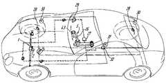
- FIG. 1shows the general layout of a vehicle provided with a manual control means for an electric steering and brake device according to the invention.
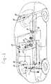
- FIG. 2shows the general layout of the electric steering device according to the invention.
- FIG. 3shows a cross-section of the screw actuator.
- the vehicle shown in FIG. 1comprises a screw actuator 1 which is connected to the front wheels of the vehicle, as well as ajoystick 26 situated near the driver's seat.
- the joystick 26may have integrated pressure buttons 43 .
- electromechanical brake actuators 28are provided which control the disk brakes on all wheels of the vehicle, and which also may be controlled by the joystick 26 .
- Electromechanical drum brakesmay also form a part of a complete electromechanical brake system.
- the joystick 26is connected to an electronic control unit 27 , which through the driving dynamic controller 29 controls the electric motor 2 of the screw actuator 1 .
- the joystick 26also controls the electromechanical brake actuators 28 on the basis of signals received from the wheel speed sensors 30 . Furthermore, sensors 31 have been incorporated which monitor the driving status, all sensors being connected to the sensor electronics control device 32 .
- the control unit 27receives signals related, e.g., to the load exerted on the screw actuator 1 , displacements and/or rotations of components thereof, through cable 33 .
- the control unit 27receives signals from the joystick 26 .
- the electric motor 2is controlled, through cable 35 , for actuating the screw actuator 1 .
- the joystick 26is mounted at the free end of the lever 23 , which is rotatable around a vertical axis on the swivel point 24 . Furthermore, the lever 23 can pivot about the horizontal pivot axis of the hinge 36 .
- the immobilization means 25e.g. an electromagnetic coupling
- the lever 23By means of the immobilization means 25 , e.g. an electromagnetic coupling, the lever 23 , and thereby the joystick 26 are held in a nominal position under nominal conditions, that is when electric current is available.
- the electromagnetic coupling 25is released and by manipulating the lever 23 through the joystick 26 , a rotation through swivel 24 is imparted on the flexible cable 4 which is capable to transmit a torque.
- this flexible cable 4drives the screw actuator 1 in such a way that steering action is still possible.
- a flexible brake cable 37is provided, which, in the absence of an electric power, is controlled by pivoting the lever 23 about the hinge 36 .
- the flexible cable 37is connected to the brake actuators 28 , but is not shown in further detail.
- the actuator appliedcan be executed with a rotating nut and a moving screw, or a moving nut and a rotating screw.
- the screw actuator 1is accommodated in a housing 19 , which is non-rotatably fixed with respect to e.g., the chassis of a vehicle.
- the nut 12is immovably fixed within the housing 12 .
- the screw 13is rotatably and translatably supported within the nut 12 by means of the balls 38 , which engage correspondingly shaped screw threads in the nut 12 and the screw 13 .
- the screw actuator 1is actuated through an electric motor 2 which two bevel pinion 39 drives a first reduction bevel gear 40 which is positioned around the screw 13 .
- the bevel gear 40is rotatably supported by means of bearing 41 .
- the bevel gear 40is integrated with a sun gear wheel 8 , which engages satellite gear wheels 10 .
- the housing 1carries a fixed ring gear wheel 9 , which also engages the satellite gear wheels 10 .
- the satellite gear wheels 10are rotatably mounted on a carrier 11 , which through the spline/ball mechanism 20 is able to rotate the screw 13 .
- the bevel gears 39 , 40 , as well as the satellite gear wheel mechanism 8 – 11provide the necessary reduction of the motor rotations for driving the screw actuator 1 .
- a mechanical back-up systemcomprising a flexible cable 4 , which is connected to electromagnetic coupling 6 .
- the electromagnetic coupling 6connects the flexible cable 4 to the auxiliary drive (bevel) gear wheel 14 .
- the auxiliary drive gear wheel 14engages a bevel gear 21 , which surrounds the screw 13 .
- the bevel gear 21is integrated with an auxiliary carrier 15 , rotatably supported with respect to the housing by means of the bearing 42 .
- the carrier 15carries auxiliary satellite gear wheels 16 , which engage a fixed auxiliary ring gear wheel 17 , as well as an auxiliary sun gear wheel 18 integrated with the carrier 11 .
- the bevel gears 14 , 21 or other appropriate gear transmission principlesare accelerating preferably for accelerating gear wheels.
Landscapes
- Engineering & Computer Science (AREA)
- Chemical & Material Sciences (AREA)
- Combustion & Propulsion (AREA)
- Transportation (AREA)
- Mechanical Engineering (AREA)
- Automation & Control Theory (AREA)
- General Physics & Mathematics (AREA)
- Physics & Mathematics (AREA)
- Power Steering Mechanism (AREA)
- Steering Control In Accordance With Driving Conditions (AREA)
- Steering Controls (AREA)
- Mechanical Control Devices (AREA)
- Motorcycle And Bicycle Frame (AREA)
Abstract
Description
The invention is related to the field of manual control means for electrically driven steering and/or decelerating and/or accelerating of a road vehicle. Such control of vehicles is becoming more important as a result of recent developments related to electromechanical actuators, e.g. screw actuators for driving the vehicle brakes, steering column, clutch etc.
The purely mechanical control of standard brakes etc. relies on mechanical or hydraulic links, such as the hydraulic piping in the case of brakes, and the rotating steering column. The flexible cable or lever drive connected to the accelerator pedal, are also well known.
It is envisaged, however, that the full benefits of electrically steering devices etc. will be obtained with regard to manual control means that are adapted to the electric character thereof. This would enable to select a more flexible design of, e.g., the routing of the command links through the vehicle, and would also save costs. On the other hand, the overall safety level of the vehicle should not be impaired, in particular, a possible electric power interruption.
The object of the invention is, therefore, to provide a manual control means which is specifically adapted to the electric character of recent steering, braking, and accelerating devices etc., and which also can ensure the required safety level.
This object is achieved by the invention in that a manual control means is provided for the electrically driven and controlled steering, and/or accelerating and/or decelerating of a road vehicle, comprising: a hand grip means; sensors for sensing a force and/or a movement imposed on the hand grip means which correspond to a desired steering direction, and/or acceleration and/or deceleration of the vehicle; and manual lever means comprising at least one mechanical connection for mechanically steering, and/or accelerating, and/or decelerating of the vehicle in the absence of electric power, such as in the case of an electric power failure or in the case of electric power switched off, maintenance, garage parking etc., where the manual lever means being rotatable about at least one axis for actuating said at least one mechanical connection.
The manual control means according to the invention comprises first of all a hand grip means which is influenced by the human hand so as to provide the desired steering, and/or decelerating and/or accelerating signals. These signals can be conveyed to the respective electromechanical actuator devices through electric cables, which enables a flexible routing. Additionally, the manual control means comprise a mechanical back-up device for each function, which makes it possible to achieve a safe conduct of the vehicle in the case of a power interruption. For example, the manual control means can achieve a safe conduct of the vehicle in an emergency situation, but the mechanical back-up system can also be used in other circumstances, e.g. during maintenance, garage parking, etc.
During mechanical control of the vehicle, the control forces to be exerted on the hand grip means should remain limited for the driver so as to maintain control over the vehicle. Preferably the hand grip means is at one end of the manual lever means, the other end of said manual lever means being swivelable about at least one axis and comprising a mechanical connection which provides a displacement and/or a rotation upon swiveling the manual lever means about said axis.
In particular, the manual lever means is swivelable about two non parallel axes and comprises two mechanical connections which each provide a displacement and/or a rotation upon swiveling the manual lever means about the corresponding axis. This manually operated lever provides, e.g., a rotating torque which is high enough for steering the vehicle, while at the same time operating forces to be exerted by the driver can remain limited.
According to a preferred embodiment, a support means is provided which carries a first swivel having a first swivel axis, a second swivel being provided on the first swivel and having a second swivel axis transverse with respect to the first swivel axis, the manual lever means being connected to the second swivel, and an immobilization means which immobilizes the manual lever means with respect to the support means in the case of nominal operation and availability of electric power, and which allows swiveling motion in the case of power failure.
During normal operation, the control of the vehicle takes place entirely through the electric sensors of the hand grip means, e.g. a joystick which provide the signals required for steering, decelerating and/or accelerating. The joystick can be with or without integrated buttons. In the case of electric power failure, the handgrip means can make additional swiveling motions so as to perform these functions in a purely mechanical way.
The immobilization means may also comprise an electromagnetic coupling.
Although reference has been made before to the control of electromechanical actuators, electro-hydraulic actuators can also be controlled by the manual control means according to the invention.
The invention will now be described further with reference to an electromechanical steering device according to the invention, as shown in the drawings.
The vehicle shown inFIG. 1 comprises ascrew actuator 1 which is connected to the front wheels of the vehicle, as well asajoystick 26 situated near the driver's seat. Thejoystick 26 may have integratedpressure buttons 43. Furthermore,electromechanical brake actuators 28 are provided which control the disk brakes on all wheels of the vehicle, and which also may be controlled by thejoystick 26. Electromechanical drum brakes may also form a part of a complete electromechanical brake system.
Thejoystick 26 is connected to anelectronic control unit 27, which through the drivingdynamic controller 29 controls the electric motor2 of thescrew actuator 1.
Thejoystick 26 also controls theelectromechanical brake actuators 28 on the basis of signals received from thewheel speed sensors 30. Furthermore,sensors 31 have been incorporated which monitor the driving status, all sensors being connected to the sensorelectronics control device 32.
As shown inFIG. 2 , thecontrol unit 27 receives signals related, e.g., to the load exerted on thescrew actuator 1, displacements and/or rotations of components thereof, throughcable 33. Throughcable 34, thecontrol unit 27 receives signals from thejoystick 26. On the basis of these signals, the electric motor2 is controlled, throughcable 35, for actuating thescrew actuator 1.
Thejoystick 26 is mounted at the free end of thelever 23, which is rotatable around a vertical axis on theswivel point 24. Furthermore, thelever 23 can pivot about the horizontal pivot axis of thehinge 36.
By means of the immobilization means25, e.g. an electromagnetic coupling, thelever 23, and thereby thejoystick 26 are held in a nominal position under nominal conditions, that is when electric current is available.
In the absence of electric current, e.g. when the electric current is switched off or in case of an electric power failure, theelectromagnetic coupling 25 is released and by manipulating thelever 23 through thejoystick 26, a rotation throughswivel 24 is imparted on the flexible cable4 which is capable to transmit a torque.
In turn, this flexible cable4 drives thescrew actuator 1 in such a way that steering action is still possible.
Additionally, a flexible brake cable37 is provided, which, in the absence of an electric power, is controlled by pivoting thelever 23 about thehinge 36. The flexible cable37 is connected to thebrake actuators 28, but is not shown in further detail.
The actuator applied can be executed with a rotating nut and a moving screw, or a moving nut and a rotating screw.
As shown inFIG. 3 , thescrew actuator 1 is accommodated in ahousing 19, which is non-rotatably fixed with respect to e.g., the chassis of a vehicle. Thenut 12 is immovably fixed within thehousing 12. Thescrew 13 is rotatably and translatably supported within thenut 12 by means of theballs 38, which engage correspondingly shaped screw threads in thenut 12 and thescrew 13.
Thescrew actuator 1 is actuated through an electric motor2 which twobevel pinion 39 drives a firstreduction bevel gear 40 which is positioned around thescrew 13. Thebevel gear 40 is rotatably supported by means of bearing41. Thebevel gear 40 is integrated with asun gear wheel 8, which engagessatellite gear wheels 10. Thehousing 1 carries a fixedring gear wheel 9, which also engages thesatellite gear wheels 10.
Thesatellite gear wheels 10 are rotatably mounted on acarrier 11, which through the spline/ball mechanism 20 is able to rotate thescrew 13.
Thebevel gears gear wheel mechanism 8–11 provide the necessary reduction of the motor rotations for driving thescrew actuator 1.
In case of an electric power interruption, the electric motor2 is no longer able to drive thescrew actuator 1. For this reason, a mechanical back-up system is provided, comprising a flexible cable4, which is connected toelectromagnetic coupling 6. In case of a power interruption, theelectromagnetic coupling 6 connects the flexible cable4 to the auxiliary drive (bevel)gear wheel 14. The auxiliarydrive gear wheel 14 engages abevel gear 21, which surrounds thescrew 13. Thebevel gear 21 is integrated with anauxiliary carrier 15, rotatably supported with respect to the housing by means of thebearing 42.
Thecarrier 15 carries auxiliarysatellite gear wheels 16, which engage a fixed auxiliary ring gear wheel17, as well as an auxiliarysun gear wheel 18 integrated with thecarrier 11.
By rotating the flexible cable through the lever23 (seeFIG. 2 ) thescrew 13 can thus be rotated mechanically.
The bevel gears14,21 or other appropriate gear transmission principles are accelerating preferably for accelerating gear wheels.
Claims (14)
1. Manual control means for at least one of electrically driven and controlled steering, accelerating, and decelerating of a road vehicle, comprising:
a hand grip means;
sensors for sensing at least one of a force and a movement imposed on the hand grip means which correspond to at least one of a desired steering direction, acceleration, and deceleration of the vehicle;
a support means which is fixed with respect to the vehicle;
manual lever means including:
at least one mechanical connection for at least one of mechanically steering, accelerating, and decelerating of the vehicle in the absence of electric power, wherein the manual lever means is swivelable or rotatable about at least one axis with respect to the support means, characterized by an immobilization means which immobilizes the manual lever means with respect to the support means in case of nominal operation and availability of electric power, and which allows swiveling motion in case of power failure.
2. Control means according toclaim 1 , wherein the immobilization means includes an electromagnetic coupling.
3. Control means according toclaim 2 , wherein the lever means engages a gear reduction.
4. Control means according toclaim 2 , wherein the handgrip means is a joystick with integrated pressure buttons.
5. Control means according toclaim 2 , wherein support means is provided which carries a first gear wheel having a first gear wheel axis, a second gear wheel being provided on the first gear wheel having a second gear wheel axis transverse with respect to the first gear wheel axis, the manual lever means being connected to the second gear wheel.
6. Control means according toclaim 2 , wherein the handgrip means is a joystick without integrated pressure buttons.
7. Control means according toclaim 1 , wherein the lever means engages a gear reduction.
8. Control means according toclaim 7 , wherein the handgrip means is a joystick with integrated pressure buttons.
9. Control means according toclaim 7 , wherein the support means is provided which carries a first gear wheel having a first gear wheel axis, a second gear wheel being provided on the first gear wheel having a second gear wheel axis transverse with respect to the first gear wheel axis, the manual lever means being connected to the second gear wheel.
10. Control means according toclaim 7 , wherein the handgrip means is a joystick without integrated pressure buttons.
11. Control means according toclaim 1 , wherein the handgrip means is a joystick with integrated pressure buttons.
12. Control means according toclaim 11 , wherein the support means is provided which carries a first gear wheel having a first gear wheel axis, a second gear wheel being provided on the first gear wheel having a second gear wheel axis transverse with respect to the first gear wheel axis the manual lever means being connected to the second gear wheel.
13. Control means according toclaim 1 , wherein athe support means is provided which carries a first gear wheel having a first gear wheel axis, a second gear wheel being provided on the first gear wheel having a second gear wheel axis transverse with respect to the first gear wheel axis, the manual lever means being connected to the second gear wheel.
14. Control means according toclaim 1 , wherein the handgrip means is a joystick without integrated pressure buttons.
Applications Claiming Priority (3)
| Application Number | Priority Date | Filing Date | Title |
|---|---|---|---|
| NL1014912ANL1014912C2 (en) | 2000-04-11 | 2000-04-11 | Hand control means. |
| NL1014912 | 2000-04-11 | ||
| PCT/NL2001/000290WO2001076932A1 (en) | 2000-04-11 | 2001-04-11 | Vehicle control with manual back up |
Publications (2)
| Publication Number | Publication Date |
|---|---|
| US20030173136A1 US20030173136A1 (en) | 2003-09-18 |
| US7021416B2true US7021416B2 (en) | 2006-04-04 |
Family
ID=19771192
Family Applications (1)
| Application Number | Title | Priority Date | Filing Date |
|---|---|---|---|
| US10/240,116Expired - Fee RelatedUS7021416B2 (en) | 2000-04-11 | 2001-04-11 | Vehicle control with manual back up |
Country Status (9)
| Country | Link |
|---|---|
| US (1) | US7021416B2 (en) |
| EP (1) | EP1272384B1 (en) |
| JP (1) | JP2003530266A (en) |
| KR (1) | KR20020089441A (en) |
| CN (1) | CN1261322C (en) |
| AU (1) | AU2001250654A1 (en) |
| DE (1) | DE60101842T2 (en) |
| NL (1) | NL1014912C2 (en) |
| WO (1) | WO2001076932A1 (en) |
Cited By (46)
| Publication number | Priority date | Publication date | Assignee | Title |
|---|---|---|---|---|
| US20050205311A1 (en)* | 2002-05-14 | 2005-09-22 | Toyota Jidosha Kabushiki Kaisha | Motor vehicle control device |
| US20100071920A1 (en)* | 2008-09-19 | 2010-03-25 | James Ching Sik Lau | Power tool |
| DE102016204560A1 (en) | 2016-03-18 | 2017-09-21 | Ford Global Technologies, Llc | Steering system for a steerable vehicle |
| US9809155B2 (en) | 2015-10-27 | 2017-11-07 | Steering Solutions Ip Holding Corporation | Retractable steering column assembly having lever, vehicle having retractable steering column assembly, and method |
| US9828016B2 (en) | 2015-06-24 | 2017-11-28 | Steering Solutions Ip Holding Corporation | Retractable steering column system, vehicle having the same, and method |
| US9840271B2 (en) | 2015-06-29 | 2017-12-12 | Steering Solutions Ip Holding Corporation | Retractable steering column with rake limiter |
| US9845106B2 (en)* | 2015-08-31 | 2017-12-19 | Steering Solutions Ip Holding Corporation | Overload protection for belt drive mechanism |
| US9849904B2 (en) | 2015-07-31 | 2017-12-26 | Steering Solutions Ip Holding Corporation | Retractable steering column with dual actuators |
| US9862403B1 (en) | 2016-11-29 | 2018-01-09 | Steering Solutions Ip Holding Corporation | Manually retractable steering column assembly for autonomous vehicle |
| US9919724B2 (en) | 2015-05-29 | 2018-03-20 | Steering Solutions Ip Holding Corporation | Retractable steering column with manual retrieval |
| US10029725B2 (en) | 2015-12-03 | 2018-07-24 | Steering Solutions Ip Holding Corporation | Torque feedback system for a steer-by-wire vehicle, vehicle having steering column, and method of providing feedback in vehicle |
| US10029676B2 (en) | 2014-01-29 | 2018-07-24 | Steering Solutions Ip Holding Corporation | Hands on steering wheel detect |
| US10112639B2 (en) | 2015-06-26 | 2018-10-30 | Steering Solutions Ip Holding Corporation | Vehicle steering arrangement and method of making same |
| US10160477B2 (en) | 2016-08-01 | 2018-12-25 | Steering Solutions Ip Holding Corporation | Electric power steering column assembly |
| US10160473B2 (en) | 2016-09-13 | 2018-12-25 | Steering Solutions Ip Holding Corporation | Steering column decoupling system |
| US10160472B2 (en) | 2015-10-20 | 2018-12-25 | Steering Solutions Ip Holding Corporation | Steering column with stationary hub |
| US10189496B2 (en) | 2016-08-22 | 2019-01-29 | Steering Solutions Ip Holding Corporation | Steering assembly having a telescope drive lock assembly |
| US10239552B2 (en) | 2016-10-14 | 2019-03-26 | Steering Solutions Ip Holding Corporation | Rotation control assembly for a steering column |
| US10310605B2 (en) | 2016-11-15 | 2019-06-04 | Steering Solutions Ip Holding Corporation | Haptic feedback for steering system controls |
| US10343706B2 (en) | 2015-06-11 | 2019-07-09 | Steering Solutions Ip Holding Corporation | Retractable steering column system, vehicle having the same, and method |
| US10351160B2 (en) | 2016-11-30 | 2019-07-16 | Steering Solutions Ip Holding Corporation | Steering column assembly having a sensor assembly |
| US10351159B2 (en) | 2015-05-01 | 2019-07-16 | Steering Solutions Ip Holding Corporation | Retractable steering column with a radially projecting attachment |
| US10351161B2 (en) | 2016-05-27 | 2019-07-16 | Steering Solutions Ip Holding Corporation | Steering column with manual retraction |
| US10363958B2 (en) | 2016-07-26 | 2019-07-30 | Steering Solutions Ip Holding Corporation | Electric power steering mode determination and transitioning |
| US10370022B2 (en) | 2017-02-13 | 2019-08-06 | Steering Solutions Ip Holding Corporation | Steering column assembly for autonomous vehicle |
| US10385930B2 (en) | 2017-02-21 | 2019-08-20 | Steering Solutions Ip Holding Corporation | Ball coupling assembly for steering column assembly |
| US10384708B2 (en) | 2016-09-12 | 2019-08-20 | Steering Solutions Ip Holding Corporation | Intermediate shaft assembly for steer-by-wire steering system |
| US10399591B2 (en) | 2016-10-03 | 2019-09-03 | Steering Solutions Ip Holding Corporation | Steering compensation with grip sensing |
| US10421475B2 (en) | 2016-11-15 | 2019-09-24 | Steering Solutions Ip Holding Corporation | Electric actuator mechanism for retractable steering column assembly with manual override |
| US10421476B2 (en) | 2016-06-21 | 2019-09-24 | Steering Solutions Ip Holding Corporation | Self-locking telescope actuator of a steering column assembly |
| US10436299B2 (en) | 2015-06-25 | 2019-10-08 | Steering Solutions Ip Holding Corporation | Stationary steering wheel assembly and method |
| US10442441B2 (en) | 2015-06-15 | 2019-10-15 | Steering Solutions Ip Holding Corporation | Retractable handwheel gesture control |
| US10449927B2 (en) | 2017-04-13 | 2019-10-22 | Steering Solutions Ip Holding Corporation | Steering system having anti-theft capabilities |
| US10457313B2 (en) | 2016-06-28 | 2019-10-29 | Steering Solutions Ip Holding Corporation | ADAS wheel locking device |
| US10481602B2 (en) | 2016-10-17 | 2019-11-19 | Steering Solutions Ip Holding Corporation | Sensor fusion for autonomous driving transition control |
| US10496102B2 (en) | 2016-04-11 | 2019-12-03 | Steering Solutions Ip Holding Corporation | Steering system for autonomous vehicle |
| US10562561B2 (en) | 2016-04-25 | 2020-02-18 | Steering Solutions Ip Holding Corporation | Electrical power steering control using system state predictions |
| US10577009B2 (en) | 2015-06-16 | 2020-03-03 | Steering Solutions Ip Holding Corporation | Retractable steering column assembly and method |
| US10589774B2 (en) | 2015-05-01 | 2020-03-17 | Steering Solutions Ip Holding Corporation | Counter rotation steering wheel |
| IT201800021097A1 (en)* | 2018-12-27 | 2020-06-27 | Ferrari Spa | METHOD AND CONTROL SYSTEM OF A CAR |
| US10766518B2 (en) | 2015-06-25 | 2020-09-08 | Steering Solutions Ip Holding Corporation | Rotation control system for a steering wheel and method |
| US10780915B2 (en) | 2016-12-07 | 2020-09-22 | Steering Solutions Ip Holding Corporation | Vehicle steering system having a user experience based automated driving to manual driving transition system and method |
| US10875566B2 (en) | 2018-03-22 | 2020-12-29 | Steering Solutions Ip Holding Corporation | Stow release assembly for a manually adjustable steering column assembly |
| US10974756B2 (en) | 2018-07-31 | 2021-04-13 | Steering Solutions Ip Holding Corporation | Clutch device latching system and method |
| US11173949B2 (en)* | 2019-06-21 | 2021-11-16 | Zf Active Safety And Electronics Us Llc | Apparatus for use in turning steerable vehicle wheels |
| US11560169B2 (en) | 2015-06-11 | 2023-01-24 | Steering Solutions Ip Holding Corporation | Retractable steering column system and method |
Families Citing this family (12)
| Publication number | Priority date | Publication date | Assignee | Title |
|---|---|---|---|---|
| JP2003291821A (en)* | 2002-04-01 | 2003-10-15 | Koyo Seiko Co Ltd | Steering device for vehicle |
| FR2845342B1 (en)* | 2002-10-08 | 2005-07-01 | Renault Sa | METHOD FOR CONTROLLING A STEERING SYSTEM OF A MOTOR VEHICLE AND CONTROL DEVICE THEREFOR |
| FR2845962B1 (en)* | 2002-10-22 | 2005-07-22 | Renault Sa | CONTROL DEVICE FOR DRIVING A MOTOR VEHICLE |
| DE10352229A1 (en)* | 2003-11-08 | 2005-03-24 | Daimlerchrysler Ag | Steering system for motor vehicles, especially commercial vehicles, comprises a shaft connection which is formed of a flexible shaft over a section of its length |
| JP4111191B2 (en)* | 2004-12-28 | 2008-07-02 | 日産自動車株式会社 | Vehicle steering system |
| JP5392180B2 (en)* | 2010-05-17 | 2014-01-22 | 日産自動車株式会社 | Safety measure control device for vehicle power failure |
| CN105835857B (en)* | 2016-04-12 | 2018-06-29 | 吉林大学 | Automobile-used brake-by-wire device with flexible redundant unit |
| AT518994B1 (en)* | 2016-10-25 | 2018-03-15 | MAN TRUCK & BUS OESTERREICH GesmbH | Steering system for a motor vehicle, preferably driving school motor vehicle |
| JP6410162B1 (en)* | 2017-07-24 | 2018-10-24 | 有限会社 波多野巌松堂書店 | Driving support device, driving support method and program |
| CN107839666B (en)* | 2017-11-15 | 2023-05-12 | 力帆实业(集团)股份有限公司 | Handbrake device with self-locking function |
| CN109159848B (en)* | 2018-08-23 | 2020-03-17 | 杭州容大智造科技有限公司 | Parking system with hand brake direction control mechanism |
| DE102021202073A1 (en) | 2021-03-04 | 2022-09-08 | Robert Bosch Gesellschaft mit beschränkter Haftung | Operating arrangement for a steer-by-wire steering system of a motor vehicle |
Citations (16)
| Publication number | Priority date | Publication date | Assignee | Title |
|---|---|---|---|---|
| US3256951A (en)* | 1963-08-19 | 1966-06-21 | Rudy J Hart | Power steering for a motor vehicle |
| US3275093A (en)* | 1964-09-04 | 1966-09-27 | Walter S Pawl | Hand combined vehicle steering, power, and braking control handle |
| GB2165664A (en) | 1984-10-10 | 1986-04-16 | Johnson Engineering Corp | Remote controller for motor vehicle |
| US5002032A (en) | 1988-04-09 | 1991-03-26 | Robert Bosch Gmbh | Apparatus to control an internal combustion engine in vehicles |
| US5086870A (en) | 1990-10-31 | 1992-02-11 | Division Driving Systems, Inc. | Joystick-operated driving system |
| US5131483A (en)* | 1991-01-28 | 1992-07-21 | Shivvers, Inc. | Single lever control |
| US5275250A (en) | 1991-10-29 | 1994-01-04 | Smh Management Services | Vehicle steering control device |
| US5553684A (en)* | 1994-08-29 | 1996-09-10 | Bolduc; Scott A. | Single-unit system for controlling vehicle acceleration and braking |
| JPH08282505A (en)* | 1995-04-11 | 1996-10-29 | Yamaha Motor Co Ltd | Small-size vehicle |
| US5680797A (en)* | 1993-03-03 | 1997-10-28 | Nbb Machrichtentechnik Gmbh & Co. Kg | Manual control appliance with a control lever |
| JPH1086683A (en)* | 1996-09-17 | 1998-04-07 | Fukue Sawada | Automobile capable of selecting automatic transmission and manual transmission |
| JPH10230843A (en)* | 1998-03-12 | 1998-09-02 | Sanyo Electric Co Ltd | Golf cart |
| USH1831H (en)* | 1998-12-18 | 2000-02-01 | Caterpillar Inc. | Ergonomic motor grader vehicle control apparatus |
| US6209677B1 (en)* | 1998-09-09 | 2001-04-03 | Daimlerchrysler Ag | Steering system for non-tracked motor vehicles |
| US6263753B1 (en)* | 1999-11-27 | 2001-07-24 | Juan Froehlich | Control device for motor vehicle steering, brake and accelerator |
| US6896090B2 (en)* | 2002-06-21 | 2005-05-24 | Koyo Seiko Co., Ltd. | Vehicle steering device |
- 2000
- 2000-04-11NLNL1014912Apatent/NL1014912C2/ennot_activeIP Right Cessation
- 2001
- 2001-04-11JPJP2001574421Apatent/JP2003530266A/enactivePending
- 2001-04-11EPEP01923982Apatent/EP1272384B1/ennot_activeExpired - Lifetime
- 2001-04-11DEDE60101842Tpatent/DE60101842T2/ennot_activeExpired - Fee Related
- 2001-04-11AUAU2001250654Apatent/AU2001250654A1/ennot_activeAbandoned
- 2001-04-11CNCNB018079547Apatent/CN1261322C/ennot_activeExpired - Fee Related
- 2001-04-11USUS10/240,116patent/US7021416B2/ennot_activeExpired - Fee Related
- 2001-04-11KRKR1020027013516Apatent/KR20020089441A/ennot_activeCeased
- 2001-04-11WOPCT/NL2001/000290patent/WO2001076932A1/enactiveIP Right Grant
Patent Citations (16)
| Publication number | Priority date | Publication date | Assignee | Title |
|---|---|---|---|---|
| US3256951A (en)* | 1963-08-19 | 1966-06-21 | Rudy J Hart | Power steering for a motor vehicle |
| US3275093A (en)* | 1964-09-04 | 1966-09-27 | Walter S Pawl | Hand combined vehicle steering, power, and braking control handle |
| GB2165664A (en) | 1984-10-10 | 1986-04-16 | Johnson Engineering Corp | Remote controller for motor vehicle |
| US5002032A (en) | 1988-04-09 | 1991-03-26 | Robert Bosch Gmbh | Apparatus to control an internal combustion engine in vehicles |
| US5086870A (en) | 1990-10-31 | 1992-02-11 | Division Driving Systems, Inc. | Joystick-operated driving system |
| US5131483A (en)* | 1991-01-28 | 1992-07-21 | Shivvers, Inc. | Single lever control |
| US5275250A (en) | 1991-10-29 | 1994-01-04 | Smh Management Services | Vehicle steering control device |
| US5680797A (en)* | 1993-03-03 | 1997-10-28 | Nbb Machrichtentechnik Gmbh & Co. Kg | Manual control appliance with a control lever |
| US5553684A (en)* | 1994-08-29 | 1996-09-10 | Bolduc; Scott A. | Single-unit system for controlling vehicle acceleration and braking |
| JPH08282505A (en)* | 1995-04-11 | 1996-10-29 | Yamaha Motor Co Ltd | Small-size vehicle |
| JPH1086683A (en)* | 1996-09-17 | 1998-04-07 | Fukue Sawada | Automobile capable of selecting automatic transmission and manual transmission |
| JPH10230843A (en)* | 1998-03-12 | 1998-09-02 | Sanyo Electric Co Ltd | Golf cart |
| US6209677B1 (en)* | 1998-09-09 | 2001-04-03 | Daimlerchrysler Ag | Steering system for non-tracked motor vehicles |
| USH1831H (en)* | 1998-12-18 | 2000-02-01 | Caterpillar Inc. | Ergonomic motor grader vehicle control apparatus |
| US6263753B1 (en)* | 1999-11-27 | 2001-07-24 | Juan Froehlich | Control device for motor vehicle steering, brake and accelerator |
| US6896090B2 (en)* | 2002-06-21 | 2005-05-24 | Koyo Seiko Co., Ltd. | Vehicle steering device |
Cited By (52)
| Publication number | Priority date | Publication date | Assignee | Title |
|---|---|---|---|---|
| US7178613B2 (en)* | 2002-05-14 | 2007-02-20 | Toyota Jidosha Kabushiki Kaisha | Vehicle operating apparatus |
| US20050205311A1 (en)* | 2002-05-14 | 2005-09-22 | Toyota Jidosha Kabushiki Kaisha | Motor vehicle control device |
| US20100071920A1 (en)* | 2008-09-19 | 2010-03-25 | James Ching Sik Lau | Power tool |
| US11091148B2 (en) | 2014-01-29 | 2021-08-17 | Steering Solutions Ip Holding Corporation | Hands on steering wheel detect |
| US10029676B2 (en) | 2014-01-29 | 2018-07-24 | Steering Solutions Ip Holding Corporation | Hands on steering wheel detect |
| US10351159B2 (en) | 2015-05-01 | 2019-07-16 | Steering Solutions Ip Holding Corporation | Retractable steering column with a radially projecting attachment |
| US10589774B2 (en) | 2015-05-01 | 2020-03-17 | Steering Solutions Ip Holding Corporation | Counter rotation steering wheel |
| US9919724B2 (en) | 2015-05-29 | 2018-03-20 | Steering Solutions Ip Holding Corporation | Retractable steering column with manual retrieval |
| US11560169B2 (en) | 2015-06-11 | 2023-01-24 | Steering Solutions Ip Holding Corporation | Retractable steering column system and method |
| US10343706B2 (en) | 2015-06-11 | 2019-07-09 | Steering Solutions Ip Holding Corporation | Retractable steering column system, vehicle having the same, and method |
| US10442441B2 (en) | 2015-06-15 | 2019-10-15 | Steering Solutions Ip Holding Corporation | Retractable handwheel gesture control |
| US10577009B2 (en) | 2015-06-16 | 2020-03-03 | Steering Solutions Ip Holding Corporation | Retractable steering column assembly and method |
| US9828016B2 (en) | 2015-06-24 | 2017-11-28 | Steering Solutions Ip Holding Corporation | Retractable steering column system, vehicle having the same, and method |
| US10436299B2 (en) | 2015-06-25 | 2019-10-08 | Steering Solutions Ip Holding Corporation | Stationary steering wheel assembly and method |
| US10766518B2 (en) | 2015-06-25 | 2020-09-08 | Steering Solutions Ip Holding Corporation | Rotation control system for a steering wheel and method |
| US10112639B2 (en) | 2015-06-26 | 2018-10-30 | Steering Solutions Ip Holding Corporation | Vehicle steering arrangement and method of making same |
| US9840271B2 (en) | 2015-06-29 | 2017-12-12 | Steering Solutions Ip Holding Corporation | Retractable steering column with rake limiter |
| US9849904B2 (en) | 2015-07-31 | 2017-12-26 | Steering Solutions Ip Holding Corporation | Retractable steering column with dual actuators |
| US9845106B2 (en)* | 2015-08-31 | 2017-12-19 | Steering Solutions Ip Holding Corporation | Overload protection for belt drive mechanism |
| US10160472B2 (en) | 2015-10-20 | 2018-12-25 | Steering Solutions Ip Holding Corporation | Steering column with stationary hub |
| US9809155B2 (en) | 2015-10-27 | 2017-11-07 | Steering Solutions Ip Holding Corporation | Retractable steering column assembly having lever, vehicle having retractable steering column assembly, and method |
| US10029725B2 (en) | 2015-12-03 | 2018-07-24 | Steering Solutions Ip Holding Corporation | Torque feedback system for a steer-by-wire vehicle, vehicle having steering column, and method of providing feedback in vehicle |
| US10501111B2 (en) | 2016-03-18 | 2019-12-10 | Ford Global Technologies, Llc | Steering system for a steerable vehicle |
| DE102016204560A1 (en) | 2016-03-18 | 2017-09-21 | Ford Global Technologies, Llc | Steering system for a steerable vehicle |
| US10496102B2 (en) | 2016-04-11 | 2019-12-03 | Steering Solutions Ip Holding Corporation | Steering system for autonomous vehicle |
| US10562561B2 (en) | 2016-04-25 | 2020-02-18 | Steering Solutions Ip Holding Corporation | Electrical power steering control using system state predictions |
| US10351161B2 (en) | 2016-05-27 | 2019-07-16 | Steering Solutions Ip Holding Corporation | Steering column with manual retraction |
| US10421476B2 (en) | 2016-06-21 | 2019-09-24 | Steering Solutions Ip Holding Corporation | Self-locking telescope actuator of a steering column assembly |
| US10457313B2 (en) | 2016-06-28 | 2019-10-29 | Steering Solutions Ip Holding Corporation | ADAS wheel locking device |
| US10363958B2 (en) | 2016-07-26 | 2019-07-30 | Steering Solutions Ip Holding Corporation | Electric power steering mode determination and transitioning |
| US10160477B2 (en) | 2016-08-01 | 2018-12-25 | Steering Solutions Ip Holding Corporation | Electric power steering column assembly |
| US10189496B2 (en) | 2016-08-22 | 2019-01-29 | Steering Solutions Ip Holding Corporation | Steering assembly having a telescope drive lock assembly |
| US10384708B2 (en) | 2016-09-12 | 2019-08-20 | Steering Solutions Ip Holding Corporation | Intermediate shaft assembly for steer-by-wire steering system |
| US10160473B2 (en) | 2016-09-13 | 2018-12-25 | Steering Solutions Ip Holding Corporation | Steering column decoupling system |
| US10399591B2 (en) | 2016-10-03 | 2019-09-03 | Steering Solutions Ip Holding Corporation | Steering compensation with grip sensing |
| US10239552B2 (en) | 2016-10-14 | 2019-03-26 | Steering Solutions Ip Holding Corporation | Rotation control assembly for a steering column |
| US10676126B2 (en) | 2016-10-14 | 2020-06-09 | Steering Solutions Ip Holding Corporation | Rotation control assembly for a steering column |
| US10481602B2 (en) | 2016-10-17 | 2019-11-19 | Steering Solutions Ip Holding Corporation | Sensor fusion for autonomous driving transition control |
| US10421475B2 (en) | 2016-11-15 | 2019-09-24 | Steering Solutions Ip Holding Corporation | Electric actuator mechanism for retractable steering column assembly with manual override |
| US10310605B2 (en) | 2016-11-15 | 2019-06-04 | Steering Solutions Ip Holding Corporation | Haptic feedback for steering system controls |
| US9862403B1 (en) | 2016-11-29 | 2018-01-09 | Steering Solutions Ip Holding Corporation | Manually retractable steering column assembly for autonomous vehicle |
| US10351160B2 (en) | 2016-11-30 | 2019-07-16 | Steering Solutions Ip Holding Corporation | Steering column assembly having a sensor assembly |
| US10780915B2 (en) | 2016-12-07 | 2020-09-22 | Steering Solutions Ip Holding Corporation | Vehicle steering system having a user experience based automated driving to manual driving transition system and method |
| US10370022B2 (en) | 2017-02-13 | 2019-08-06 | Steering Solutions Ip Holding Corporation | Steering column assembly for autonomous vehicle |
| US10385930B2 (en) | 2017-02-21 | 2019-08-20 | Steering Solutions Ip Holding Corporation | Ball coupling assembly for steering column assembly |
| US10449927B2 (en) | 2017-04-13 | 2019-10-22 | Steering Solutions Ip Holding Corporation | Steering system having anti-theft capabilities |
| US10875566B2 (en) | 2018-03-22 | 2020-12-29 | Steering Solutions Ip Holding Corporation | Stow release assembly for a manually adjustable steering column assembly |
| US10974756B2 (en) | 2018-07-31 | 2021-04-13 | Steering Solutions Ip Holding Corporation | Clutch device latching system and method |
| EP3674172A1 (en)* | 2018-12-27 | 2020-07-01 | FERRARI S.p.A. | Car control method and system |
| IT201800021097A1 (en)* | 2018-12-27 | 2020-06-27 | Ferrari Spa | METHOD AND CONTROL SYSTEM OF A CAR |
| US11214292B2 (en) | 2018-12-27 | 2022-01-04 | Ferrari S.P.A. | Car control method and system |
| US11173949B2 (en)* | 2019-06-21 | 2021-11-16 | Zf Active Safety And Electronics Us Llc | Apparatus for use in turning steerable vehicle wheels |
Also Published As
| Publication number | Publication date |
|---|---|
| CN1441738A (en) | 2003-09-10 |
| NL1014912C2 (en) | 2001-10-12 |
| DE60101842D1 (en) | 2004-02-26 |
| EP1272384A1 (en) | 2003-01-08 |
| EP1272384B1 (en) | 2004-01-21 |
| AU2001250654A1 (en) | 2001-10-23 |
| KR20020089441A (en) | 2002-11-29 |
| WO2001076932A1 (en) | 2001-10-18 |
| CN1261322C (en) | 2006-06-28 |
| US20030173136A1 (en) | 2003-09-18 |
| DE60101842T2 (en) | 2004-12-16 |
| JP2003530266A (en) | 2003-10-14 |
Similar Documents
| Publication | Publication Date | Title |
|---|---|---|
| US7021416B2 (en) | Vehicle control with manual back up | |
| US7052427B2 (en) | Electric screw actuator system | |
| JP5406096B2 (en) | Car driving support device and car | |
| US6263997B1 (en) | Motor vehicle with at least one part which can be controlled by at least one operating lever | |
| US20050057031A1 (en) | Joystick-operated driving system | |
| CN114407597B (en) | Control system of vehicle and hovercar | |
| KR19980701602A (en) | A MOTOR-DRIVEN SYSTEM FOR STEERING A VEHICLE | |
| US6848545B2 (en) | Brake actuation assembly for a vehicle | |
| KR101382996B1 (en) | System and method for reducing turning radius of vehicle | |
| US20060113149A1 (en) | Operating mechanism for a parking break | |
| KR102535277B1 (en) | Electric parking brake for electromotive forklift truc | |
| JP7484626B2 (en) | Braking system for work vehicles | |
| CN114407596B (en) | Control system and hovercar | |
| KR20030017627A (en) | Electric steering system with mechanical back-up device | |
| KR20060134441A (en) | Electric parking brake | |
| CN111791942B (en) | Electronically controlled angle steering gear assembly | |
| JPS6350212Y2 (en) | ||
| JP3490347B2 (en) | Transmission shift operating device | |
| JPS63312275A (en) | Auxiliary braking device | |
| JP2502838Y2 (en) | Parking brake device | |
| CN118004267A (en) | Distributed intelligent automobile steering wheel steering auxiliary device and control method thereof | |
| KR20100015059A (en) | Safe parking system | |
| JP2002173010A (en) | Vehicle brake system | |
| KR20040019144A (en) | Intelligent driving systems for handicapped person | |
| KR20070065009A (en) | Pedal Device for Disabled Person's Car |
Legal Events
| Date | Code | Title | Description |
|---|---|---|---|
| AS | Assignment | Owner name:SKF ENGINEERING AND RESEARCH CENTRE B.V., NETHERLA Free format text:ASSIGNMENT OF ASSIGNORS INTEREST;ASSIGNORS:KAPAAN, HENDRIKUS JAN;HOLWEG, EDUARDUS GERARDUS MARIA;NERVO, AURELIO;REEL/FRAME:013230/0440 Effective date:20021031 | |
| REMI | Maintenance fee reminder mailed | ||
| LAPS | Lapse for failure to pay maintenance fees | ||
| STCH | Information on status: patent discontinuation | Free format text:PATENT EXPIRED DUE TO NONPAYMENT OF MAINTENANCE FEES UNDER 37 CFR 1.362 | |
| FP | Lapsed due to failure to pay maintenance fee | Effective date:20100404 |