US7021313B1 - Respiratory suction catheter apparatus with improved valve and collar - Google Patents
Respiratory suction catheter apparatus with improved valve and collarDownload PDFInfo
- Publication number
- US7021313B1 US7021313B1US09/716,486US71648600AUS7021313B1US 7021313 B1US7021313 B1US 7021313B1US 71648600 AUS71648600 AUS 71648600AUS 7021313 B1US7021313 B1US 7021313B1
- Authority
- US
- United States
- Prior art keywords
- catheter
- distal end
- adapter
- collar
- manifold
- Prior art date
- Legal status (The legal status is an assumption and is not a legal conclusion. Google has not performed a legal analysis and makes no representation as to the accuracy of the status listed.)
- Expired - Lifetime, expires
Links
Images


Classifications
- A—HUMAN NECESSITIES
- A61—MEDICAL OR VETERINARY SCIENCE; HYGIENE
- A61M—DEVICES FOR INTRODUCING MEDIA INTO, OR ONTO, THE BODY; DEVICES FOR TRANSDUCING BODY MEDIA OR FOR TAKING MEDIA FROM THE BODY; DEVICES FOR PRODUCING OR ENDING SLEEP OR STUPOR
- A61M16/00—Devices for influencing the respiratory system of patients by gas treatment, e.g. ventilators; Tracheal tubes
- A61M16/04—Tracheal tubes
- A61M16/0463—Tracheal tubes combined with suction tubes, catheters or the like; Outside connections
Definitions
- the present inventionrelates to a respiratory suction catheter system with an improved mechanism for cleaning the tip of the catheter without drawing an excessive amount of air from the respiration circuit to which the endotracheal catheter is attached. More specifically, the present invention relates principally to a closed suction endotracheal catheter system which provides improved cleaning of the catheter while minimizing or eliminating air drawn from the patient's respiration circuit.
- an artificial airwaysuch as an endotracheal tube
- the artificial airway's functionis primarily to keep the patient's airway open so that adequate lung ventilation can be maintained during the procedure.
- the endotracheal tubewill be left in the patient for a prolonged period of time. For example, with many patients, the endotracheal tube will remain in place to sustain mechanical ventilation for the life of the patient.
- patient secretionscan contain infectious diseases, such as streptococcus, pseudomonus, staphylococcus and even HIV, it is important to shield clinicians from them. Likewise, it is important to shield patients from communicable pathogens in the environment. This is particulary important because such patients often have compromised immune systems.
- closed suction cathetersThe advantage of closed suction catheters is that the ventilating circuit is not detached from the patient during suction procedures, as it is during open suction procedures.
- the catheteris reused a number of times over a twenty-four hour period, it is important that mucus and other secretions be cleaned from the catheter prior to periods of non-use. If the secretions are not removed, the risk of auto-contamination increases. It is also important to clean the lumen of the catheter to maintain suction efficiency.
- suctionalso causes a volume of respiratory air to be removed through the catheter.
- the air that is evacuatedpotentially disrupts the carefully controlled ventilatory cycles.
- the amount of respiratory air available to the patientis potentially decreased as a result of catheter cleaning. If the clinician has a hard time cleaning secretions from the catheter, suction may be applied through the catheter several times—thereby repeatedly drawing air from the ventilatory circuit.
- closed suction cathetershave been developed to have a cleaning or lavage chamber which is physically isolated from the respiration circuit.
- a closed suction catheterwhich has a lavage chamber configured to receive the distal tip of the catheter as it is withdrawn from the manifold.
- a wallis then slid from an open position to a closed position to isolate the distal end of the catheter from the manifold and the respiration circuit.
- a portis commonly provided to inject lavage solution into the cleaning chamber.
- the closed suction catheters presently availablesuffer from the inability to clean the catheter tip to the most desirable extent. If pathogens or other contaminants remain on the catheter for too long, they can auto-contaminate the patient. Additionally, if mucus and other secretions dry on the catheter, they can interfere with the suction efficiency, present an unsightly appearance and necessitate premature replacement of the closed suction catheter apparatus. Thus, there is a need for a catheter apparatus which has a mechanism for more effectively cleaning the distal end of the catheter without creating a substantial draw on respiratory air in the ventilation circuit.
- an improved respiratory suction catheter apparatuswhich includes a manifold for attachment to an artificial airway, such as an endotracheal tube, to form a ventilation circuit, a catheter which is displaceable through the manifold and into the artificial airway to suction secretions from the artificial airway and lungs, and a valve mechanism disposed adjacent the ventilation circuit to minimize the air drawn from the respiration circuit of a patient while the catheter is being cleaned.
- an artificial airwaysuch as an endotracheal tube
- the valve mechanismis configured to automatically engage the catheter tip after it is withdrawn through the manifold to thereby minimize the amount of air drawn into the catheter during cleaning.
- valve mechanismis provided with an air makeup to allow makeup air into the catheter and thereby ensure proper evacuation of secretions, and any liquid used to clean the catheter.
- an air turbulence enhancing mechanismis provided for increasing turbulent airflow around the distal end of the catheter to thereby improve removal of secretions from the catheter.
- an air makeup mechanismis disposed so as to provide makeup air to the distal end of the catheter which is not drawn from the ventilation circuit.
- FIG. 1shows a cross-sectional view of a manifold and catheter cleansing mechanism in accordance with the teachings of the prior art
- FIG. 2shows a cross-sectional view of a manifold and catheter cleaning mechanism in accordance with the teachings of another embodiment of the prior art
- FIG. 3Ashows a cross-sectional view of the manifold and catheter of an improved respiratory suction catheter apparatus with a valve member in an open position in accordance with the principles of the present invention
- FIG. 3Bshows a cross-sectional view of the manifold and catheter shown in FIG. 3A , with the valve in a second, closed position;
- FIG. 3Cshows a fragmented, close-up cross-sectional view of one embodiment of the improved respiratory suction catheter apparatus shown in FIG. 3A ;
- FIG. 3Dshows a fragmented, close-up cross-sectional view of another embodiment of the improved respiratory suction catheter apparatus shown in FIG. 3A ;
- FIG. 3Eshows a cross-sectional view of an embodiment similar to those shown in FIGS. 3A through 3D , but wherein the flap engages the collar;
- FIG. 4Ashows a fragmented, cross-sectional view of an alternative embodiment of an improved respiratory suction catheter apparatus having a valve in an open position in accordance with the principles of the present invention
- FIG. 4Bshows a fragmented, cross-sectional view of the embodiment of FIG. 4A , wherein the valve is in a closed position to isolate the catheter from the ventilation circuit;
- FIG. 4Cshows a fragmented, cross-sectional view of the embodiment of FIGS. 4A and 4B , with an air makeup mechanism in an open position to facilitate suctioning of mucus and the like;
- FIG. 5Ashows a cross-sectional view of an alternative embodiment of an improved respiratory suction catheter apparatus having a valve in an open position in accordance with the principles of the present invention
- FIG. 5Bshows a cross-sectional view of the embodiment shown in FIG. 5A with the valve in a closed position
- FIG. 5Cshows a partial cross-sectional view of the valve of the embodiment shown in FIGS. 5A and 5B ;
- FIG. 6Ashows a cross-sectional view of yet another alternative embodiment of an improved respiratory suction catheter apparatus made in accordance with the principles of the present invention
- FIG. 6Bshows a cross-sectional view of the embodiment shown in FIG. 6A in a closed configuration
- FIGS. 6C and 6Dshow end views of the valve mechanism of the embodiment shown in FIGS. 6A and 6B in a relaxed position and with a catheter extending therethrough, respectively;
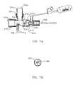
- FIG. 7Ashows a cross-sectional view of still another embodiment of an improved respiratory suction catheter apparatus made in accordance with the principles of the present invention.
- FIG. 7Bshows a partial end view of the improved respiratory suction catheter apparatus of FIG. 7A in a closed position
- FIG. 8Ashows a cross-sectional view of still yet another embodiment of an improved respiratory suction catheter apparatus made in accordance with the principles of the present invention.
- FIG. 8Bshows a cross-section view of the improved endotracheal catheter of FIG. 8A , wherein the valve mechanism is in a closed configuration.
- FIG. 1there is shown a cross-sectional view of a manifold 10 and catheter cleansing mechanism 14 in accordance with the teachings of the prior art.
- the manifold 10has a valve mechanism in the form of a rotatable rod 18 for selectively isolating a lavage chamber 20 from the ventilation circuit 26 .
- a lavage solutioncan be injected through a side port 30 to help wash the mucus and other secretions from the exterior of the catheter 22 .
- the lavage chamberis not configured for makeup air to enter when the rotatable rod 18 is closed, a vacuum can be created in the lavage chamber 20 which interferes with effective suctioning.
- FIG. 1An additional disadvantage of the embodiment shown in FIG. 1 is that the closure mechanism for such devices must typically be manually activated. If the user fails to close the rotatable rod 18 , actuation of suction through the catheter will draw air from the ventilation circuit 26 .
- FIG. 2there is shown a cross-sectional view of an alternative embodiment of the prior art.
- the manifold 100is provided with a plurality of ports 104 .
- a first port 104 ais attached to the hub of an endotracheal tube of the patient to conduct respiratory air to and from the endotracheal tube.
- the manifoldforms part of a respiration circuit.
- the airis typically provided to and removed from the manifold through a second port 104 b which is attached to a pair of ventilation tubes via a connector (not shown).
- the ventilation tubesare, in turn, connected to a mechanical ventilator (not shown) in a manner which will be well known to those skilled in the art.
- a third port 104 cis provided opposite the second port 104 b .
- the third port 104 cis typically covered with a cap 108 which is removed when “blow-by” is desired to wean a patient from forced ventilation.
- the manifoldalso has a fourth port 104 d .
- a coupling 112is configured to form a force-fit engagement with the fourth port 104 d and effectively connects the catheter 116 and a protective sleeve 120 to the manifold 100 .
- Disposed at a proximal end of the coupling 112is a lavage port 124 through which a cleaning liquid can be injected to rinse the exterior of the catheter 116 .
- a lavage port 124is positioned adjacent a seal 128 which is configured to wipe mucus and other secretions from the catheter 116 as is drawn through the seal.
- a userwill typically withdraw the catheter 116 until the distal end 116 a thereof is positioned slightly distally of the seal 128 , and then the cleaning solution will be injected into the lavage port 124 to assist in the removal of secretions. While such a method of removing the secretions is generally effective, it draws air from the ventilation circuit 132 . Additionally, it is common for respiratory therapists and other clinicians to maintain the suction on as the distal end 116 a of the catheter 116 is drawn from the first port 104 a to a position immediately adjacent the seal 128 .
- FIG. 3Athere is shown a cross-sectional view of a portion of an improved endotracheal catheter, generally indicated at 200 .
- the endotracheal catheterincludes a manifold, generally indicated at 204 , and a catheter 208 .
- the manifold 204includes a plurality of ports 212 a–c .
- a first port 212 ais configured for attachment to the proximal end of an artificial airway, such as the hub of an endotracheal tube, tracheostomy tube, etc.
- a second port 212 bis typically connected to a pair of ventilator tubes (not shown) by means of an adaptor (not shown), in accordance with common practice in the art.
- conditional inspiratory airis forced through one of the ventilator tubes, through the second port 212 b and the first port 212 a and into the patient's lungs via the artificial airway. Exhaled air is carried through the first port 212 a and then the second port 212 b and out through the other ventilator tube.
- the manifold 204forms part of a respiration circuit 214 through which respiratory air is cycled.
- a third port 212 cis also forming part of the manifold 204 .
- the third port 212 cis typically covered by a cap 216 .
- the cap 216may be removed from the third port 212 c so that oxygenated air is passed by the patient's endotracheal tube, but inspiratory air is not forced into the patient by means of a totally closed circuit. This situation, commonly called “blow-by,” enables the patient to gradually resume natural or spontaneous breathing.
- the manifold 204also has a fourth port 212 d .
- the fourth port 212 dis disposed generally opposite the first port 212 a and is configured to allow the catheter 208 to slide therethrough and into the first port to enable suctioning of the patient. At the completion of suctioning, the catheter 208 is pulled back into the fourth port 212 d to prevent interference with the respiration circuit 214 .
- a coupling or adapter 220Disposed between the wall forming the fourth port 212 d and the catheter 208 is a coupling or adapter 220 .
- the adapter 220engages the wall defining the fourth port 212 d .
- the adapter 220engages a collar 224 which closely surrounds the catheter 208 so as to leave a small cylindrical space 226 around the catheter 208 .
- the space between the catheter 208 and the collar 224is between 0.005 and 0.015 inch. This proximity provides two important advantages.
- While the collar 224 configuration shown in FIG. 3Ais beneficial, it is still common to have secretions build up on the distal end 208 a of the catheter 208 . If such build up is not promptly removed, it can interfere with the ability of the catheter to properly suction the patient. It can also serve as a culture medium for pathogens within the closed suction catheter system.
- a flap 232is hingedly attached to an annular ring 236 disposed inside the fourth port 212 d so as to enable the flap 232 to pivot with respect to the ring.
- the flap 232could be attached directly to the wall of the manifold 204 defining the fourth port 212 d or to the adapter 220 .
- the hinged attachment 240allows the flap 232 to selectively move while maintaining alignment with the catheter tip, thereby creating a flap valve.
- the flap 232is positioned to align with the distal end 208 a of the catheter 208 when the catheter is almost completely withdrawn into the collar 224 .
- the hinged attachment 240is sufficiently flexible that suction through the distal end 208 a of the catheter 208 will draw the flap 232 into contact with the distal end of the catheter.
- the catheter 208includes a primary aperture 244 in the distal end 208 a and one or more lateral apertures 248 positioned slightly proximal from the distal end.
- suction through catheter tip aperture 244is dramatically reduced or eliminated.
- Decrease in suction flow through the aperture 244causes increased suction flow in the lateral apertures 248 , thereby increasing the ability of the lateral apertures to evacuate any secretions contained between the outside of the catheter 208 and the interior of the collar 224 .
- the lateral apertures 248are generally smaller than the distal aperture 244 and because airflow to the lateral apertures is limited by the collar 224 , a substantial decrease in the amount of air drawn from the respiration circuit is achieved while simultaneously improving cleaning of the catheter 208 .
- the proximal side 232 a(i.e. the side opposite the respiration circuit 214 ) of the flap 232 is generally planar. In such a configuration, the proximal side 232 a of the flap 232 will typically form a substantially complete seal with the distal end 208 a of the catheter 208 .
- FIG. 3Cthere is shown a close-up cross-sectional view of the embodiment shown in FIGS. 3A and 3B with a slight modification to the flap 232 .
- the flap 232 J in FIG. 3Chas a channel 252 formed therein on the proximal side 232 a ′.
- the channel 252prevents the flap 232 ′ from forming an airtight engagement with the distal end 208 a of the catheter 208 .
- the channel 252ensures that a measured volume of air will be drawn into the aperture 244 at the distal most end of the catheter.
- the volume of air drawn through the channel 252can have an important affect. Specifically, the air creates turbulent airflow both within the catheter 208 and immediately around its exterior. The turbulent airflow, in turn, assists in breaking up agglomerations of mucus and secretions which lavage/cleaning solution alone may not. Thus, the turbulent airflow helps to provide improved cleaning of the distal end 208 a of the catheter 208 .
- FIG. 3Dthere is shown yet another variation of the flap 232 shown in FIGS. 3A and 3B .
- the flap 232 ′′has an aperture 260 formed therein so as to allow a relatively small amount of air to pass through the flap 232 ′′.
- the small holecreates turbulent airflow at the distal end 208 a of the catheter 208 and thereby improves cleaning. It is currently believed that an aperture 260 in the flap 232 ′′ with a diameter of about 0.02 is preferred.
- FIGS. 3A through 3DWhile shown in FIGS. 3A through 3D as engaging the distal end 208 a of the catheter 208 , the flap 232 forming a flap valve need not engage the catheter itself.
- FIG. 3Eshows an embodiment similar to those shown in FIGS. 3A through 3D , except that the flap 232 is disposed to engage the distal end 224 a of the collar 224 rather than the distal end 208 a of the catheter 208 . In such a configuration, suction flow can still be achieved through the aperture 244 at the distal end 208 a of the catheter 208 .
- a source of makeup airwill be provided. This can be accomplished by using either of the flap configurations shown in FIGS. 3C and 3D .
- a small holecan be formed in the collar 224 to facilitate a small amount of makeup air being present to enhance suction flow and to increase turbulence.
- the resultis an improved ability to clean the distal end 208 a of the catheter 208 , while at the same time significantly reducing the amount of air which is withdrawn from the respiration circuit 214 .
- consistent ventilationis provided to the patient, and the clinician is able to more easily clean the catheter 208 .
- FIG. 4Athere is shown another embodiment of an improved respiratory suction catheter apparatus, generally indicated at 300 , made in accordance with the principles of the present invention.
- the improved respiratory suction catheter apparatus 300includes a manifold 304 and a catheter 308 .
- the manifold 304includes a first port 312 a , a second port 312 b , a third port 312 c and a fourth port 312 d.
- An adapter 320is disposed in the fourth port 312 d in such a manner as to make the manifold 304 and the catheter 308 a functionally integrated unit.
- the adapter 320may be adhesively attached to the manifold 304 , or may be simply force-fit.
- annular ringis not disposed in the manifold 304 independent of the adapter 320 . Rather, an annular ring 326 extends inwardly from a distal end 320 a of the adapter 320 ′. The annular ring 326 defines an aperture or opening 330 through which the catheter 308 can be extended. Thus, the opening 330 is slightly larger than the exterior of the catheter 308 .
- a flap 336is also extending inwardly from the adapter 320 .
- the flap 336is preferably hingedly attached to either the adapter directly or to the annular ring 326 .
- the flapwill generally extend distally from the annular ring 326 and provide virtually no resistance to advancement of the catheter 308 .
- FIGS. 4A through 4Chas a makeup air inlet, generally indicated at 350 which is formed in a portion of the wall defining the fourth port 312 d of the manifold and the adapter 320 .
- the makeup air inlet 350preferably includes a filter 354 which is selected to substantially prevent cross-contamination between the environment/clinicians and the patient.
- a flexible barrier 358Disposed adjacent to the filter material is a flexible barrier 358 which forms a one-way valve 360 .
- the one-way valve 360will generally be closed when the catheter 308 is in an extended position, wherein the catheter extends through the opening 330 in the annular ring 326 .
- a vacuumwill quickly develop on the side of the flap 336 opposite the respiration circuit 340 .
- the vacuumcauses the one-way valve 360 to open and allow a supply of makeup air to enter the chamber.
- the makeup air flowing past the flexible one-way valve member 360helps to create turbulent airflow and facilitate removal of any respiratory secretions on the catheter 308 .
- the one-way valve 360could be configured to provide very little resistance to air inflow, or could be configured to require a substantial vacuum to be present before makeup air is allowed into the area proximal the flap 336 .
- FIG. 5Athere is shown a fragmented, cross-sectional view of an alternative embodiment of an improved respiratory suction catheter apparatus, generally indicated at 400 .
- the respiratory suction catheter apparatusincludes a manifold 404 and a catheter 408 which is moveable through the manifold to suction secretions from a patient's lungs.
- the manifoldincludes a first port 412 a for attachment to an endotracheal tube or other artificial airway, a second port 412 b for attachment to the ventilator tubes of a mechanical ventilator, a third port 412 c which is covered with a cap 416 , and a fourth port 412 d which receives the connector or adaptor 420 .
- valve 424Disposed at the distal end 420 a of the adaptor 420 is a valve 424 in a configuration which is commonly referred to as a duckbill valve.
- the valve 424is formed by a piece of resilient material which opens as the catheter 408 is advanced therethrough, and closes when the catheter is withdrawn.
- the valve 424is attached to the adaptor 420 by a flexible base 428 .
- an air inlet 432which includes a filter material 436 and a resilient member 440 configured to form a one-way valve 444 similar to that discussed in the previous embodiment.
- a filter material 436and a resilient member 440 configured to form a one-way valve 444 similar to that discussed in the previous embodiment.
- the valve 424 shown in FIGS. 5A through 5Cis substantially advanced in several respects.
- the interior of the valve 424has helical grooves 450 formed therein.
- the helical grooves 450help to create turbulent airflow around the distal end 408 a of the catheter 408 .
- the flexible base 428is configured to allow the valve 420 to be drawn toward the collar 460 to thereby reduce space and improve removal of secretions from the exterior of the catheter 408 .
- FIG. 5Bthere is shown a cross-sectional view similar to that shown in FIG. 5A , but with the distal end 408 a of the catheter 408 in a retracted position.
- the suction through the catheterworks against the flexible base 428 of the valve and draws the valve toward the collar 460 .
- a pair of air inlets 470are disposed at the base 428 of the valve 424 and allow air into the valve.
- valve 424will return to the position shown in FIG. 5A , except that it will be closed as the catheter 408 remains substantially in the collar until the next use.
- FIG. 6Athere is shown a cross-sectional view of yet another alternative embodiment of an improved endotracheal catheter made in accordance with the principles of the present invention.
- the endotracheal catheter 500includes a manifold 504 and a catheter 508 .
- the manifold 504has a first port 512 a for attachment to the hub of an artificial airway of a patient, and a second port 512 b for attachment to the ventilator tubes (not shown) of a mechanical ventilator so as to define a ventilation circuit 516 .
- the manifoldalso includes a third port 512 c which is configured to receive the catheter 508 .
- a third port 512 cDisposed in the third port 512 c are a pair of floating flexible disks or membranes 520 and 524 .
- Each of the disksdefines an aperture or opening 528 and 532 , respectively, through which the catheter 508 may be slid.
- An end view of the disks 520 and 524 with the catheter being slid therethroughis shown in FIG. 6D .
- a second lavage port 550can be added distally from the disks.
- the second lavage port 550would typically not be used for cleaning of the catheter 508 .
- FIG. 7Athere is shown a cross-sectional view of still another embodiment of an improved endotracheal catheter made in accordance with the principles of the present invention.
- Most portions of the endotracheal catheter shown in FIG. 7Aare the same as those discussed with respect to FIGS. 6A through 6D and are numbered accordingly.
- the one major difference between the embodiments of FIGS. 6A through 6D and FIG. 7Ais that the disks 520 and 524 of the previous embodiment are replaced with a resilient closing membrane 570 which is attached at one end 570 a to the manifold 504 and at an opposing end 570 b to an adapter 572 holding the catheter 508 .
- the adapter 572 or manifold 504can be rotated to twist the membrane 570 and thereby either reduce or enlarge the size of a hole 580 ( FIG. 7B ) formed by the material.
- a hole 580FIG. 7B
- the adapter 572 or manifold 504can be rotated to twist the membrane 570 and thereby either reduce or enlarge the size of a hole 580 ( FIG. 7B ) formed by the material.
- the resilient material 570When suctioning of patient is desired, the resilient material 570 is rotated to allow the catheter to pass therethrough. Because swivels 574 are disposed on the first and second ports 512 a and 512 b , the rotation of the resilient material to expand or contract the hole therethrough will provide virtually no discomfort to the patient, while effectively controlling the amount of air which is drawn from the respiration circuit 516 when the distal end 508 a of the catheter 508 is being cleaned.
- FIG. 7Bshows an end view of the resilient membrane 570 .
- the respiratory suction catheter apparatus 600includes a manifold 604 and a catheter 608 which is moveable through the manifold.
- the manifold 604includes a first port 612 a for connection to the hub of an endotracheal tube, a second port 612 b for connection (via ventilator tubes) to a mechanical ventilator, and a third port 612 c and cap 616 which can be used for blow-by.
- the fourth port 612 dis different from those discussed previously because it has a shroud 620 placed therein.
- the shroud 620is attached to a plunger 624 so as to allow the user to move the shroud between a first position adjacent the sidewall of the fourth port 612 d ( FIG. 8A ) and a second position ( FIG. 8B ) wherein the shroud is disposed approximately at the center of port 612 d.
- the shroud 620will typically be moved into the first position so that it does not interfere with advancement of the catheter 608 through the manifold 604 .
- the catheter 608is withdrawn into the collar 634 .
- the plunger 624is then pressed so as to move the shroud 620 over the distal end 634 a of the collar 634 to cover the distal end 608 a of the catheter 608 .
- the catheter 608will then be advanced toward the distal end 620 a of the shroud 620 .
- Lavage/cleaning solutionwill then be applied through the lavage port 640 while suction is applied.
- a small gapcan be formed between the shroud 620 and the collar 634 to ensure turbulent airflow into the distal end 608 a of the catheter 608 .
- grooves or some other patternmay be formed in the shroud to encourage turbulent airflow.
- a valve membermay be included to allow for makeup air in a similar manner as discussed with several of the embodiments above.
Landscapes
- Health & Medical Sciences (AREA)
- Pulmonology (AREA)
- Emergency Medicine (AREA)
- Engineering & Computer Science (AREA)
- Anesthesiology (AREA)
- Biomedical Technology (AREA)
- Heart & Thoracic Surgery (AREA)
- Hematology (AREA)
- Life Sciences & Earth Sciences (AREA)
- Animal Behavior & Ethology (AREA)
- General Health & Medical Sciences (AREA)
- Public Health (AREA)
- Veterinary Medicine (AREA)
- External Artificial Organs (AREA)
Abstract
Description
Claims (12)
Priority Applications (1)
| Application Number | Priority Date | Filing Date | Title |
|---|---|---|---|
| US09/716,486US7021313B1 (en) | 1998-09-21 | 2000-11-20 | Respiratory suction catheter apparatus with improved valve and collar |
Applications Claiming Priority (2)
| Application Number | Priority Date | Filing Date | Title |
|---|---|---|---|
| US15760598A | 1998-09-21 | 1998-09-21 | |
| US09/716,486US7021313B1 (en) | 1998-09-21 | 2000-11-20 | Respiratory suction catheter apparatus with improved valve and collar |
Related Parent Applications (1)
| Application Number | Title | Priority Date | Filing Date |
|---|---|---|---|
| US15760598AContinuation | 1998-09-17 | 1998-09-21 |
Publications (1)
| Publication Number | Publication Date |
|---|---|
| US7021313B1true US7021313B1 (en) | 2006-04-04 |
Family
ID=22564470
Family Applications (1)
| Application Number | Title | Priority Date | Filing Date |
|---|---|---|---|
| US09/716,486Expired - LifetimeUS7021313B1 (en) | 1998-09-21 | 2000-11-20 | Respiratory suction catheter apparatus with improved valve and collar |
Country Status (1)
| Country | Link |
|---|---|
| US (1) | US7021313B1 (en) |
Cited By (25)
| Publication number | Priority date | Publication date | Assignee | Title |
|---|---|---|---|---|
| US20040221842A1 (en)* | 2003-05-06 | 2004-11-11 | Madsen Edward B. | Respiratory apparatus having an instrument introduction section and manifold |
| US20050199243A1 (en)* | 2000-04-06 | 2005-09-15 | Unomedical A/S | Manifold |
| US20100147310A1 (en)* | 2008-12-12 | 2010-06-17 | John Brewer | Respiratory Access Port Assembly With Push Button Lock and Method of Use |
| US20100147312A1 (en)* | 2008-12-12 | 2010-06-17 | John Brewer | Respiratory Access Port Assembly With Pin Lock and Method of Use |
| US20100154799A1 (en)* | 2008-12-23 | 2010-06-24 | John Brewer | Respiratory access assembly with rotating lock and method |
| US20100288282A1 (en)* | 2009-05-15 | 2010-11-18 | John Brewer | Respiratory Access Port Assembly With Passive Lock And Method Of Use |
| WO2011020985A1 (en) | 2009-08-20 | 2011-02-24 | Smiths Medical International Limited | Ventilation and suction systems and assemblies |
| US9078987B2 (en) | 2011-12-23 | 2015-07-14 | Avent, Inc. | Clutch brake assembly for a respiratory access port |
| US20160263342A1 (en)* | 2015-03-09 | 2016-09-15 | Phillip Polin | Tracheal humidification device |
| US10143814B2 (en) | 2011-03-29 | 2018-12-04 | Teleflex Life Sciences Unlimited Company | Fluid input module for multi-lumen catheters |
| US20190076608A1 (en)* | 2017-08-09 | 2019-03-14 | Eric A. Cantor | Supraglottic airway device |
| WO2019077292A1 (en) | 2017-10-20 | 2019-04-25 | Smiths Medical International Limited | Suction catheter assemblies |
| US10271716B2 (en) | 2008-06-27 | 2019-04-30 | C.R. Bard, Inc. | Endoscopic vacuum controller |
| US10322253B2 (en) | 2011-03-29 | 2019-06-18 | Teleflex Life Sciences Unlimited Company | Ballooned ventilation tube cleaning device |
| US10500360B1 (en) | 2014-08-29 | 2019-12-10 | Teleflex Life Sciences Unlimited Company | Catheter for cleaning of tracheal ventilation tubes |
| WO2020178540A1 (en) | 2019-03-02 | 2020-09-10 | Smiths Medical International Limited | Suction catheter assemblies and assemblies including a suction catheter assembly |
| US10926009B2 (en) | 2016-01-06 | 2021-02-23 | Teleflex Life Sciences Pte. Ltd. | Closed suction system |
| US10946153B2 (en) | 2016-05-16 | 2021-03-16 | Teleflex Life Sciences Pte. Ltd. | Mechanical user control elements for fluid input module |
| WO2021079079A1 (en) | 2019-10-22 | 2021-04-29 | Smiths Medical International Limited | Connectors and assemblies |
| US20210138178A1 (en)* | 2015-10-01 | 2021-05-13 | Mallinckrodt Hospital Products IP Unlimited Company | Device And Method For Diffusing High Concentration NO With Inhalation Therapy Gas |
| WO2021191884A1 (en)* | 2020-03-26 | 2021-09-30 | Palliare Limited | An adapter for a face mask, and an instrument shielding apparatus |
| WO2021224585A1 (en) | 2020-05-04 | 2021-11-11 | Smiths Medical International Limited | Closed-system suction catheter assemblies and methods |
| WO2022023687A1 (en) | 2020-07-28 | 2022-02-03 | Smiths Medical International Limited | Closed-system suction catheter assemblies |
| US11452831B2 (en) | 2016-01-06 | 2022-09-27 | Airway Medix S.A. | Closed suction system |
| WO2022238668A1 (en) | 2021-05-10 | 2022-11-17 | Smiths Medical International Limited | Suction catheter assemblies |
Citations (102)
| Publication number | Priority date | Publication date | Assignee | Title |
|---|---|---|---|---|
| US3240431A (en) | 1964-05-27 | 1966-03-15 | Clayton Corp Of Delaware | Combination valve spout and spray head assembly |
| US3710942A (en)* | 1967-06-02 | 1973-01-16 | Pall Corp | Valve for fluid lines and structures containing the same |
| US3831629A (en) | 1972-01-24 | 1974-08-27 | Halkey Roberts Corp | Check valve |
| US3834388A (en) | 1973-01-29 | 1974-09-10 | Cenco Medical Health Supply Co | Suction control arrangement for a suction catheter |
| US3902500A (en) | 1974-03-01 | 1975-09-02 | Gale E Dryden | Endotracheal catheter with means for positive ventilation and sterile technique |
| US3937220A (en) | 1974-03-04 | 1976-02-10 | International Paper Company | Sterile aspiration catheter |
| US3991762A (en) | 1974-09-30 | 1976-11-16 | Radford F Richard | Aspirating device for patient ventilation apparatus |
| US4015336A (en) | 1975-07-01 | 1977-04-05 | Johnson W Grant | Valve for an oral evacuator system |
| US4047527A (en) | 1975-11-21 | 1977-09-13 | Kelsen Arthur F | Oral syringe |
| US4193406A (en) | 1978-09-18 | 1980-03-18 | Jinotti Walter J | Dual purpose catheter |
| US4351328A (en) | 1980-03-27 | 1982-09-28 | Sontek Industries, Inc. | Simultaneous respiration and endotracheal suctioning of a critically ill patient |
| US4468224A (en) | 1982-01-28 | 1984-08-28 | Advanced Cardiovascular Systems, Inc. | System and method for catheter placement in blood vessels of a human patient |
| US4510933A (en) | 1982-06-16 | 1985-04-16 | Dragerwerk Aktiengesellschaft | Suction adapter and medical draining set and method of using a tracheal draining device |
| US4516573A (en) | 1982-02-23 | 1985-05-14 | Gambro Engstrom Ab | Device for connecting a respirator or anesthesia machine to a patient |
| US4529003A (en)* | 1983-03-21 | 1985-07-16 | Syntex, Inc. | Manifold |
| US4569344A (en) | 1984-07-23 | 1986-02-11 | Ballard Medical Products | Aspirating/ventilating apparatus and method |
| US4573979A (en) | 1984-08-23 | 1986-03-04 | Innovative Surgical Products, Inc. | Irrigation/aspiration tip |
| US4574173A (en) | 1984-05-04 | 1986-03-04 | Warner-Lambert Company | Device for RF welding an IV tube to a catheter lumen |
| US4573965A (en) | 1984-02-13 | 1986-03-04 | Superior Plastic Products Corp. | Device for draining wounds |
| US4595005A (en) | 1984-02-08 | 1986-06-17 | Jinotti Walter J | Dual-purpose catheter |
| US4622964A (en)* | 1983-09-28 | 1986-11-18 | O-Two Systems International Inc. | Valve for breathing device |
| US4649913A (en) | 1984-07-31 | 1987-03-17 | Smiths Industries Public Limited Company | Tracheostomy tube assemblies |
| US4657008A (en) | 1984-06-28 | 1987-04-14 | Gambro Engstrom Ab | Anesthesia and/or respirator apparatus having a moistening and/or gasification chamber |
| US4691702A (en)* | 1986-10-08 | 1987-09-08 | Becton, Dickinson And Company | Aspirating device |
| US4696305A (en) | 1985-07-15 | 1987-09-29 | Peter von Berg Extrakorporale Systems-Medizintechnik GmbH | Flow controller |
| US4705073A (en) | 1986-04-23 | 1987-11-10 | Advanced Medical Devices, Inc. | Molded plastic gate valve and sealing means therefor |
| US4834726A (en) | 1987-03-11 | 1989-05-30 | Ballard Medical Products | Medical ventilating and aspirating apparatus and methods |
| US4909248A (en) | 1988-01-09 | 1990-03-20 | Smiths Industries Public Limited Company | Tracheal tube fittings and assemblies |
| US4929426A (en) | 1987-11-02 | 1990-05-29 | Biologix, Inc. | Portable blood chemistry measuring apparatus |
| US4967743A (en) | 1987-03-11 | 1990-11-06 | Ballard Medical Products | Neonatal closed system for involuntary aspiration and ventilation, and method |
| USD312880S (en) | 1988-03-04 | 1990-12-11 | Bodai Balazs I | Neonatal suction valve |
| US5005568A (en)* | 1987-10-07 | 1991-04-09 | Hudson Respiratory Care Inc. | Isolation valve |
| US5060646A (en) | 1990-09-10 | 1991-10-29 | ||
| US5064122A (en) | 1989-08-11 | 1991-11-12 | Toko Yakuhin Kogyo Kabushiki Kaisha | Disposable nozzle adapter for intranasal spray containers |
| US5073164A (en) | 1990-05-02 | 1991-12-17 | Hollister William H | Suction catheter |
| US5083561A (en) | 1990-06-14 | 1992-01-28 | Russo Ronald D | Tracheal suction catheter |
| US5088486A (en) | 1990-04-11 | 1992-02-18 | Jinotti Walter J | Closed system reusable dual purpose catheter |
| US5107829A (en) | 1987-03-11 | 1992-04-28 | Ballard Medical Products | Neonatal closed system for involuntary aspiration and ventilation, and method |
| US5125893A (en) | 1990-04-16 | 1992-06-30 | Dryden Gale E | Suction catheter with wall lumen for irrigation |
| US5134996A (en) | 1991-01-09 | 1992-08-04 | Smiths Industries Medical Systems, Inc. | Inspiration and expiration indicator for a suction catheter |
| US5139018A (en) | 1990-07-24 | 1992-08-18 | Superior Healthcare Group, Inc. | Patient ventilating apparatus with aspirating catheter |
| US5140983A (en) | 1990-04-11 | 1992-08-25 | Jinotti Walter J | Multi purpose catheter assembly |
| US5158569A (en) | 1990-12-21 | 1992-10-27 | Ballard Medical Products | Catheter placement locking and sealing device |
| US5184611A (en) | 1991-01-04 | 1993-02-09 | Smiths Industries Public Limited Company | Tracheal tube assemblies and liners |
| US5191881A (en) | 1991-01-28 | 1993-03-09 | Genesis Medical, Ltd. | Insufflating/suctioning valve |
| US5213096A (en) | 1990-06-18 | 1993-05-25 | Gambro Engstrom Ab | Apparatus for connecting a patient to breathing devices, the apparatus including a bacteria filter and gas sampling means |
| US5215522A (en) | 1984-07-23 | 1993-06-01 | Ballard Medical Products | Single use medical aspirating device and method |
| US5224471A (en) | 1991-02-21 | 1993-07-06 | Elettro Plastica S.P.A. | Nasal dispenser for atomized pharmaceutical substances |
| US5230332A (en) | 1990-10-22 | 1993-07-27 | Ballard Medical Products | Methods and apparatus for a micro-tracheal catheter hub assembly |
| US5242084A (en) | 1992-05-26 | 1993-09-07 | Jinotti Walter J | Fluid dispensing apparatus |
| US5254098A (en) | 1993-02-16 | 1993-10-19 | Smiths Industries Medical Systems, Inc. | Suction catheter assemblies |
| US5255676A (en) | 1991-11-08 | 1993-10-26 | Russo Ronald D | Safety sealed tracheal suction system |
| US5277177A (en) | 1984-07-23 | 1994-01-11 | Ballard Medical Products | Single use medical aspirating device and method |
| US5300043A (en) | 1992-10-23 | 1994-04-05 | Smiths Industries Medical Systems, Inc. | Suction catheter valve |
| US5305762A (en) | 1992-09-21 | 1994-04-26 | Medical Graphics Corporation | Patient valve incorporating one-way check valves for infection control |
| US5309904A (en) | 1991-01-28 | 1994-05-10 | Beck Blaine E | Insufflating/suctioning valve |
| US5309902A (en) | 1992-10-19 | 1994-05-10 | Sherwood Medical Company | Respiratory support system and suction catheter device therefor |
| US5325850A (en) | 1992-09-30 | 1994-07-05 | Smith Industries Medical Systems, Inc. | Suction catheter assemblies |
| US5325851A (en) | 1991-04-01 | 1994-07-05 | Sorenson Laboratories, Inc. | Apparatus and method for ventilating and aspirating |
| US5333606A (en) | 1992-04-24 | 1994-08-02 | Sherwood Medical Company | Method for using a respirator accessory access port and adaptor therefore |
| US5333607A (en) | 1992-10-19 | 1994-08-02 | Sherwood Medical Company | Ventilator manifold with accessory access port |
| US5337780A (en) | 1992-10-19 | 1994-08-16 | Sherwood Medical Company | Suction control valve |
| US5346478A (en) | 1993-06-07 | 1994-09-13 | Jinotti Walter J | Pulmonary catheter |
| US5348542A (en)* | 1993-05-05 | 1994-09-20 | Joseph P. Padula | Holder for percutaneously introduced tubes |
| US5349950A (en) | 1992-10-28 | 1994-09-27 | Smiths Industries Medical Systems, Inc. | Suction catheter assemblies |
| US5354267A (en)* | 1993-09-20 | 1994-10-11 | Vital Signs Inc. | Irrigation and suction apparatus |
| US5355876A (en) | 1992-05-06 | 1994-10-18 | Superior Healthcare Group, Inc. | Patient ventilating apparatus with modular components |
| US5357946A (en) | 1992-10-19 | 1994-10-25 | Sherwood Medical Company | Ventilator manifold with accessory access port and adaptors therefore |
| US5368017A (en) | 1991-04-01 | 1994-11-29 | Sorenson Laboratories, Inc. | Apparatus for ventilating and aspirating |
| US5370610A (en)* | 1993-02-09 | 1994-12-06 | Reynolds; James R. | Surgical drainage tube system |
| US5385560A (en)* | 1992-10-13 | 1995-01-31 | Ethicon Endo-Surgery | Reducer for cannulae |
| US5445141A (en) | 1992-10-19 | 1995-08-29 | Sherwood Medical Company | Respiratory support system |
| US5449348A (en) | 1992-11-13 | 1995-09-12 | Hudson Respiratory Care, Inc. | Irrigation apparatus and method for suction catheters |
| US5487381A (en) | 1994-04-20 | 1996-01-30 | Jinotti; Walter J. | Closed system for treating pulmonary patient |
| US5490503A (en) | 1994-04-29 | 1996-02-13 | Smiths Industries Medical Systems, Inc. | Suction catheter having multiple valves and collet assembly |
| US5496287A (en) | 1994-07-05 | 1996-03-05 | Jinotti; Walter J. | Pulmonary suction catheter |
| US5513627A (en) | 1995-01-27 | 1996-05-07 | Flam; Gary H. | Esophageal tracheal intubator airway |
| US5513628A (en) | 1993-07-14 | 1996-05-07 | Sorenson Critical Care, Inc. | Apparatus and method for ventilating and aspirating |
| US5578006A (en) | 1992-03-20 | 1996-11-26 | Rudolf Schon | Suction catheter |
| US5582161A (en) | 1994-12-08 | 1996-12-10 | Sherwood Medical Company | Sheathed catheter adapter and method of use |
| US5582165A (en) | 1988-02-28 | 1996-12-10 | Bryan; James F. | Pre-assembled sealed, sheathed catheters and related valve elements with quick disconnect means for endotracheal suctioning |
| US5598840A (en) | 1995-03-17 | 1997-02-04 | Sorenson Critical Care, Inc. | Apparatus and method for ventilation and aspiration |
| US5605149A (en) | 1995-03-17 | 1997-02-25 | Board Of Regents, The University Of Texas System | Method and apparatus for directing air flow within an intubated patient |
| US5613663A (en)* | 1994-11-29 | 1997-03-25 | B. Braun Melsungen Ag | Valve device |
| US5628306A (en) | 1992-10-19 | 1997-05-13 | Kee; Kok-Hiong | Respiratory manifold with accessory access port |
| US5642726A (en) | 1994-10-18 | 1997-07-01 | Alcove Medical, Inc. | Reduced internal volume neonatal suction adaptor |
| US5664594A (en) | 1994-12-29 | 1997-09-09 | Sherwood Medical Company | Cleaning device for ventilator manifold and method of use thereof |
| US5676136A (en) | 1993-12-07 | 1997-10-14 | Russo; Ronald D. | Protective suction control catheter with valve |
| US5715815A (en)* | 1995-03-28 | 1998-02-10 | Ballard Medical Products, Inc. | Sheath sterility preservation filter and seal for suction catheters |
| US5730123A (en)* | 1994-05-18 | 1998-03-24 | Ballard Medical Products | Medical multiple access low dead space anti-microbial aspirating/ventilating closed system improvements and methods |
| US5735271A (en)* | 1994-05-18 | 1998-04-07 | Ballard Medical Products | Multiple access adaptors for monitoring, sampling, medicating, aspirating, and ventilating the respiratory tract of a patient |
| US5769093A (en)* | 1994-12-09 | 1998-06-23 | Xomed Surgical Products, Inc. | Method of relieving synovial fluid pressure |
| US5769702A (en) | 1996-02-01 | 1998-06-23 | Sorenson Critical Care, Inc. | Variable positioning gaseous conduit orifice and method of use |
| US5775325A (en)* | 1995-05-11 | 1998-07-07 | Russo; Ronald D. | Two part closed tracheal suction system |
| US5792113A (en)* | 1996-12-12 | 1998-08-11 | Ethicon Endo-Surgerym Inc. | Universal seal for a trocar |
| US5813402A (en) | 1997-04-09 | 1998-09-29 | Jinotti; Walter J. | Valve for pulmonary catheter |
| US5855562A (en) | 1997-01-07 | 1999-01-05 | Hudson Respiratory Care Inc. | Suction control valve |
| US5882348A (en) | 1997-02-03 | 1999-03-16 | Sorenson Critical Care, Inc. | Valved manifold |
| US5919174A (en) | 1997-02-03 | 1999-07-06 | Sorenson Critical Care, Inc. | Suction valve assembly |
| US6165168A (en)* | 1997-09-02 | 2000-12-26 | Russo; Ronald D. | Closed system adapter for catheters |
| US6176234B1 (en) | 1997-08-08 | 2001-01-23 | Salter Labs | Mouthpiece for a nebulizer |
| US6227200B1 (en)* | 1998-09-21 | 2001-05-08 | Ballard Medical Products | Respiratory suction catheter apparatus |
- 2000
- 2000-11-20USUS09/716,486patent/US7021313B1/ennot_activeExpired - Lifetime
Patent Citations (108)
| Publication number | Priority date | Publication date | Assignee | Title |
|---|---|---|---|---|
| US3240431A (en) | 1964-05-27 | 1966-03-15 | Clayton Corp Of Delaware | Combination valve spout and spray head assembly |
| US3710942A (en)* | 1967-06-02 | 1973-01-16 | Pall Corp | Valve for fluid lines and structures containing the same |
| US3831629A (en) | 1972-01-24 | 1974-08-27 | Halkey Roberts Corp | Check valve |
| US3834388A (en) | 1973-01-29 | 1974-09-10 | Cenco Medical Health Supply Co | Suction control arrangement for a suction catheter |
| US3902500A (en) | 1974-03-01 | 1975-09-02 | Gale E Dryden | Endotracheal catheter with means for positive ventilation and sterile technique |
| US3937220A (en) | 1974-03-04 | 1976-02-10 | International Paper Company | Sterile aspiration catheter |
| US3991762A (en) | 1974-09-30 | 1976-11-16 | Radford F Richard | Aspirating device for patient ventilation apparatus |
| US4015336A (en) | 1975-07-01 | 1977-04-05 | Johnson W Grant | Valve for an oral evacuator system |
| US4047527A (en) | 1975-11-21 | 1977-09-13 | Kelsen Arthur F | Oral syringe |
| US4193406A (en) | 1978-09-18 | 1980-03-18 | Jinotti Walter J | Dual purpose catheter |
| US4351328A (en) | 1980-03-27 | 1982-09-28 | Sontek Industries, Inc. | Simultaneous respiration and endotracheal suctioning of a critically ill patient |
| US4468224A (en) | 1982-01-28 | 1984-08-28 | Advanced Cardiovascular Systems, Inc. | System and method for catheter placement in blood vessels of a human patient |
| US4516573A (en) | 1982-02-23 | 1985-05-14 | Gambro Engstrom Ab | Device for connecting a respirator or anesthesia machine to a patient |
| US4510933A (en) | 1982-06-16 | 1985-04-16 | Dragerwerk Aktiengesellschaft | Suction adapter and medical draining set and method of using a tracheal draining device |
| US4529003A (en)* | 1983-03-21 | 1985-07-16 | Syntex, Inc. | Manifold |
| US4622964A (en)* | 1983-09-28 | 1986-11-18 | O-Two Systems International Inc. | Valve for breathing device |
| US4595005A (en) | 1984-02-08 | 1986-06-17 | Jinotti Walter J | Dual-purpose catheter |
| US4573965A (en) | 1984-02-13 | 1986-03-04 | Superior Plastic Products Corp. | Device for draining wounds |
| US4574173A (en) | 1984-05-04 | 1986-03-04 | Warner-Lambert Company | Device for RF welding an IV tube to a catheter lumen |
| US4657008A (en) | 1984-06-28 | 1987-04-14 | Gambro Engstrom Ab | Anesthesia and/or respirator apparatus having a moistening and/or gasification chamber |
| US4569344A (en) | 1984-07-23 | 1986-02-11 | Ballard Medical Products | Aspirating/ventilating apparatus and method |
| US5215522A (en) | 1984-07-23 | 1993-06-01 | Ballard Medical Products | Single use medical aspirating device and method |
| US4638539A (en) | 1984-07-23 | 1987-01-27 | Ballard Medical Products | Aspirating/ventilating apparatus and method |
| US5277177A (en) | 1984-07-23 | 1994-01-11 | Ballard Medical Products | Single use medical aspirating device and method |
| US4649913A (en) | 1984-07-31 | 1987-03-17 | Smiths Industries Public Limited Company | Tracheostomy tube assemblies |
| US4573979A (en) | 1984-08-23 | 1986-03-04 | Innovative Surgical Products, Inc. | Irrigation/aspiration tip |
| US4696305A (en) | 1985-07-15 | 1987-09-29 | Peter von Berg Extrakorporale Systems-Medizintechnik GmbH | Flow controller |
| US4705073A (en) | 1986-04-23 | 1987-11-10 | Advanced Medical Devices, Inc. | Molded plastic gate valve and sealing means therefor |
| US4691702A (en)* | 1986-10-08 | 1987-09-08 | Becton, Dickinson And Company | Aspirating device |
| US4834726A (en) | 1987-03-11 | 1989-05-30 | Ballard Medical Products | Medical ventilating and aspirating apparatus and methods |
| US4967743A (en) | 1987-03-11 | 1990-11-06 | Ballard Medical Products | Neonatal closed system for involuntary aspiration and ventilation, and method |
| US5107829A (en) | 1987-03-11 | 1992-04-28 | Ballard Medical Products | Neonatal closed system for involuntary aspiration and ventilation, and method |
| US5005568A (en)* | 1987-10-07 | 1991-04-09 | Hudson Respiratory Care Inc. | Isolation valve |
| US4929426A (en) | 1987-11-02 | 1990-05-29 | Biologix, Inc. | Portable blood chemistry measuring apparatus |
| US4909248A (en) | 1988-01-09 | 1990-03-20 | Smiths Industries Public Limited Company | Tracheal tube fittings and assemblies |
| US5582165A (en) | 1988-02-28 | 1996-12-10 | Bryan; James F. | Pre-assembled sealed, sheathed catheters and related valve elements with quick disconnect means for endotracheal suctioning |
| USD312880S (en) | 1988-03-04 | 1990-12-11 | Bodai Balazs I | Neonatal suction valve |
| US5064122A (en) | 1989-08-11 | 1991-11-12 | Toko Yakuhin Kogyo Kabushiki Kaisha | Disposable nozzle adapter for intranasal spray containers |
| US5088486A (en) | 1990-04-11 | 1992-02-18 | Jinotti Walter J | Closed system reusable dual purpose catheter |
| US5140983A (en) | 1990-04-11 | 1992-08-25 | Jinotti Walter J | Multi purpose catheter assembly |
| US5125893A (en) | 1990-04-16 | 1992-06-30 | Dryden Gale E | Suction catheter with wall lumen for irrigation |
| US5073164A (en) | 1990-05-02 | 1991-12-17 | Hollister William H | Suction catheter |
| US5083561A (en) | 1990-06-14 | 1992-01-28 | Russo Ronald D | Tracheal suction catheter |
| US5083561B1 (en) | 1990-06-14 | 1993-05-18 | D. Russo Ronald | Tracheal suction catheter |
| US5213096A (en) | 1990-06-18 | 1993-05-25 | Gambro Engstrom Ab | Apparatus for connecting a patient to breathing devices, the apparatus including a bacteria filter and gas sampling means |
| US5139018A (en) | 1990-07-24 | 1992-08-18 | Superior Healthcare Group, Inc. | Patient ventilating apparatus with aspirating catheter |
| US5060646A (en) | 1990-09-10 | 1991-10-29 | ||
| US5230332A (en) | 1990-10-22 | 1993-07-27 | Ballard Medical Products | Methods and apparatus for a micro-tracheal catheter hub assembly |
| US5158569A (en) | 1990-12-21 | 1992-10-27 | Ballard Medical Products | Catheter placement locking and sealing device |
| US5184611A (en) | 1991-01-04 | 1993-02-09 | Smiths Industries Public Limited Company | Tracheal tube assemblies and liners |
| US5134996A (en) | 1991-01-09 | 1992-08-04 | Smiths Industries Medical Systems, Inc. | Inspiration and expiration indicator for a suction catheter |
| US5191881A (en) | 1991-01-28 | 1993-03-09 | Genesis Medical, Ltd. | Insufflating/suctioning valve |
| US5309904A (en) | 1991-01-28 | 1994-05-10 | Beck Blaine E | Insufflating/suctioning valve |
| US5224471A (en) | 1991-02-21 | 1993-07-06 | Elettro Plastica S.P.A. | Nasal dispenser for atomized pharmaceutical substances |
| US5368017A (en) | 1991-04-01 | 1994-11-29 | Sorenson Laboratories, Inc. | Apparatus for ventilating and aspirating |
| US5325851A (en) | 1991-04-01 | 1994-07-05 | Sorenson Laboratories, Inc. | Apparatus and method for ventilating and aspirating |
| US5255676A (en) | 1991-11-08 | 1993-10-26 | Russo Ronald D | Safety sealed tracheal suction system |
| US5578006A (en) | 1992-03-20 | 1996-11-26 | Rudolf Schon | Suction catheter |
| US5333606A (en) | 1992-04-24 | 1994-08-02 | Sherwood Medical Company | Method for using a respirator accessory access port and adaptor therefore |
| US5343857A (en) | 1992-04-24 | 1994-09-06 | Sherwood Medical Company | Respiratory accessory access port and adaptor therefore |
| US5355876A (en) | 1992-05-06 | 1994-10-18 | Superior Healthcare Group, Inc. | Patient ventilating apparatus with modular components |
| US5242084A (en) | 1992-05-26 | 1993-09-07 | Jinotti Walter J | Fluid dispensing apparatus |
| US5305762A (en) | 1992-09-21 | 1994-04-26 | Medical Graphics Corporation | Patient valve incorporating one-way check valves for infection control |
| US5325850A (en) | 1992-09-30 | 1994-07-05 | Smith Industries Medical Systems, Inc. | Suction catheter assemblies |
| US5385560A (en)* | 1992-10-13 | 1995-01-31 | Ethicon Endo-Surgery | Reducer for cannulae |
| US5738091A (en)* | 1992-10-19 | 1998-04-14 | Sherwood Medical Company | Suction catheter connection arrangements with automatically operated valve |
| US5337780A (en) | 1992-10-19 | 1994-08-16 | Sherwood Medical Company | Suction control valve |
| US5333607A (en) | 1992-10-19 | 1994-08-02 | Sherwood Medical Company | Ventilator manifold with accessory access port |
| US5309902A (en) | 1992-10-19 | 1994-05-10 | Sherwood Medical Company | Respiratory support system and suction catheter device therefor |
| US5357946A (en) | 1992-10-19 | 1994-10-25 | Sherwood Medical Company | Ventilator manifold with accessory access port and adaptors therefore |
| US5628306A (en) | 1992-10-19 | 1997-05-13 | Kee; Kok-Hiong | Respiratory manifold with accessory access port |
| US5445141A (en) | 1992-10-19 | 1995-08-29 | Sherwood Medical Company | Respiratory support system |
| US5300043A (en) | 1992-10-23 | 1994-04-05 | Smiths Industries Medical Systems, Inc. | Suction catheter valve |
| US5349950A (en) | 1992-10-28 | 1994-09-27 | Smiths Industries Medical Systems, Inc. | Suction catheter assemblies |
| US5460613A (en) | 1992-10-28 | 1995-10-24 | Smiths Industries Medical Systems, Inc. | Suction catheter assemblies |
| US5449348A (en) | 1992-11-13 | 1995-09-12 | Hudson Respiratory Care, Inc. | Irrigation apparatus and method for suction catheters |
| US5370610A (en)* | 1993-02-09 | 1994-12-06 | Reynolds; James R. | Surgical drainage tube system |
| US5254098A (en) | 1993-02-16 | 1993-10-19 | Smiths Industries Medical Systems, Inc. | Suction catheter assemblies |
| US5348542A (en)* | 1993-05-05 | 1994-09-20 | Joseph P. Padula | Holder for percutaneously introduced tubes |
| US5346478A (en) | 1993-06-07 | 1994-09-13 | Jinotti Walter J | Pulmonary catheter |
| US5513628A (en) | 1993-07-14 | 1996-05-07 | Sorenson Critical Care, Inc. | Apparatus and method for ventilating and aspirating |
| US5791337A (en) | 1993-07-14 | 1998-08-11 | Coles; Peter W. H. | Apparatus and method for ventilating and aspirating |
| US5354267A (en)* | 1993-09-20 | 1994-10-11 | Vital Signs Inc. | Irrigation and suction apparatus |
| US5676136A (en) | 1993-12-07 | 1997-10-14 | Russo; Ronald D. | Protective suction control catheter with valve |
| US5487381A (en) | 1994-04-20 | 1996-01-30 | Jinotti; Walter J. | Closed system for treating pulmonary patient |
| US5490503A (en) | 1994-04-29 | 1996-02-13 | Smiths Industries Medical Systems, Inc. | Suction catheter having multiple valves and collet assembly |
| US5730123A (en)* | 1994-05-18 | 1998-03-24 | Ballard Medical Products | Medical multiple access low dead space anti-microbial aspirating/ventilating closed system improvements and methods |
| US5735271A (en)* | 1994-05-18 | 1998-04-07 | Ballard Medical Products | Multiple access adaptors for monitoring, sampling, medicating, aspirating, and ventilating the respiratory tract of a patient |
| US5496287A (en) | 1994-07-05 | 1996-03-05 | Jinotti; Walter J. | Pulmonary suction catheter |
| US5642726A (en) | 1994-10-18 | 1997-07-01 | Alcove Medical, Inc. | Reduced internal volume neonatal suction adaptor |
| US5613663A (en)* | 1994-11-29 | 1997-03-25 | B. Braun Melsungen Ag | Valve device |
| US5582161A (en) | 1994-12-08 | 1996-12-10 | Sherwood Medical Company | Sheathed catheter adapter and method of use |
| US5769093A (en)* | 1994-12-09 | 1998-06-23 | Xomed Surgical Products, Inc. | Method of relieving synovial fluid pressure |
| US5664594A (en) | 1994-12-29 | 1997-09-09 | Sherwood Medical Company | Cleaning device for ventilator manifold and method of use thereof |
| US5513627A (en) | 1995-01-27 | 1996-05-07 | Flam; Gary H. | Esophageal tracheal intubator airway |
| US5605149A (en) | 1995-03-17 | 1997-02-25 | Board Of Regents, The University Of Texas System | Method and apparatus for directing air flow within an intubated patient |
| US5598840A (en) | 1995-03-17 | 1997-02-04 | Sorenson Critical Care, Inc. | Apparatus and method for ventilation and aspiration |
| US5715815A (en)* | 1995-03-28 | 1998-02-10 | Ballard Medical Products, Inc. | Sheath sterility preservation filter and seal for suction catheters |
| US5775325A (en)* | 1995-05-11 | 1998-07-07 | Russo; Ronald D. | Two part closed tracheal suction system |
| US5769702A (en) | 1996-02-01 | 1998-06-23 | Sorenson Critical Care, Inc. | Variable positioning gaseous conduit orifice and method of use |
| US5792113A (en)* | 1996-12-12 | 1998-08-11 | Ethicon Endo-Surgerym Inc. | Universal seal for a trocar |
| US5855562A (en) | 1997-01-07 | 1999-01-05 | Hudson Respiratory Care Inc. | Suction control valve |
| US5882348A (en) | 1997-02-03 | 1999-03-16 | Sorenson Critical Care, Inc. | Valved manifold |
| US5919174A (en) | 1997-02-03 | 1999-07-06 | Sorenson Critical Care, Inc. | Suction valve assembly |
| US5813402A (en) | 1997-04-09 | 1998-09-29 | Jinotti; Walter J. | Valve for pulmonary catheter |
| US6176234B1 (en) | 1997-08-08 | 2001-01-23 | Salter Labs | Mouthpiece for a nebulizer |
| US6165168A (en)* | 1997-09-02 | 2000-12-26 | Russo; Ronald D. | Closed system adapter for catheters |
| US6227200B1 (en)* | 1998-09-21 | 2001-05-08 | Ballard Medical Products | Respiratory suction catheter apparatus |
Non-Patent Citations (6)
| Title |
|---|
| Hudson RCI advertisement for "Cath-Guide", 1996. |
| U.S. Appl. No. 09/357,591, filed Jul. 20, 1999. |
| U.S. Appl. No. 09/459,522, filed Dec. 13, 1999. |
| U.S. Appl. No. 09/460,257, filed Dec. 13, 1999. |
| U.S. Appl. No. 09/471,317, filed Dec. 23, 1999. |
| U.S. Appl. No. 09/693,261, filed Oct. 20, 2000. |
Cited By (35)
| Publication number | Priority date | Publication date | Assignee | Title |
|---|---|---|---|---|
| US20050199243A1 (en)* | 2000-04-06 | 2005-09-15 | Unomedical A/S | Manifold |
| US7263997B2 (en)* | 2003-05-06 | 2007-09-04 | Kimberly-Clark Worldwide, Inc | Respiratory apparatus having an instrument introduction section and manifold |
| US20040221842A1 (en)* | 2003-05-06 | 2004-11-11 | Madsen Edward B. | Respiratory apparatus having an instrument introduction section and manifold |
| US10271716B2 (en) | 2008-06-27 | 2019-04-30 | C.R. Bard, Inc. | Endoscopic vacuum controller |
| US20100147310A1 (en)* | 2008-12-12 | 2010-06-17 | John Brewer | Respiratory Access Port Assembly With Push Button Lock and Method of Use |
| US20100147312A1 (en)* | 2008-12-12 | 2010-06-17 | John Brewer | Respiratory Access Port Assembly With Pin Lock and Method of Use |
| US8215306B2 (en) | 2008-12-12 | 2012-07-10 | Kimberly-Clark Worldwide, Inc. | Respiratory access port assembly with push button lock and method of use |
| US8845617B2 (en) | 2008-12-12 | 2014-09-30 | Kimberly-Clark Worldwide, Inc. | Respiratory access port assembly with push button lock and method of use |
| US8307829B2 (en) | 2008-12-23 | 2012-11-13 | Kimberly-Clark Worldwide, Inc. | Respiratory access assembly with rotating lock and method |
| US20100154799A1 (en)* | 2008-12-23 | 2010-06-24 | John Brewer | Respiratory access assembly with rotating lock and method |
| US20100288282A1 (en)* | 2009-05-15 | 2010-11-18 | John Brewer | Respiratory Access Port Assembly With Passive Lock And Method Of Use |
| US8256422B2 (en)* | 2009-05-15 | 2012-09-04 | Kimberly-Clark Worldwide, Inc | Respiratory access port assembly with passive lock and method of use |
| WO2011020985A1 (en) | 2009-08-20 | 2011-02-24 | Smiths Medical International Limited | Ventilation and suction systems and assemblies |
| US10322253B2 (en) | 2011-03-29 | 2019-06-18 | Teleflex Life Sciences Unlimited Company | Ballooned ventilation tube cleaning device |
| US10806884B2 (en) | 2011-03-29 | 2020-10-20 | Teleflex Life Sciences Pte. Ltd. | Ballooned ventilation tube cleaning device |
| US10143814B2 (en) | 2011-03-29 | 2018-12-04 | Teleflex Life Sciences Unlimited Company | Fluid input module for multi-lumen catheters |
| US10328224B2 (en) | 2011-03-29 | 2019-06-25 | Teleflex Life Sciences Unlimited Company | Mechanical user control of fluid input module |
| US9078987B2 (en) | 2011-12-23 | 2015-07-14 | Avent, Inc. | Clutch brake assembly for a respiratory access port |
| US10500360B1 (en) | 2014-08-29 | 2019-12-10 | Teleflex Life Sciences Unlimited Company | Catheter for cleaning of tracheal ventilation tubes |
| US9956372B2 (en)* | 2015-03-09 | 2018-05-01 | Phillip Polin | Tracheal humidification device |
| US20160263342A1 (en)* | 2015-03-09 | 2016-09-15 | Phillip Polin | Tracheal humidification device |
| US20210138178A1 (en)* | 2015-10-01 | 2021-05-13 | Mallinckrodt Hospital Products IP Unlimited Company | Device And Method For Diffusing High Concentration NO With Inhalation Therapy Gas |
| US10926009B2 (en) | 2016-01-06 | 2021-02-23 | Teleflex Life Sciences Pte. Ltd. | Closed suction system |
| US11452831B2 (en) | 2016-01-06 | 2022-09-27 | Airway Medix S.A. | Closed suction system |
| US10946153B2 (en) | 2016-05-16 | 2021-03-16 | Teleflex Life Sciences Pte. Ltd. | Mechanical user control elements for fluid input module |
| US20190076608A1 (en)* | 2017-08-09 | 2019-03-14 | Eric A. Cantor | Supraglottic airway device |
| US10869979B2 (en)* | 2017-08-09 | 2020-12-22 | Eric A. Cantor | Supraglottic airway device |
| US11857709B2 (en) | 2017-08-09 | 2024-01-02 | Eric A. Cantor | Supraglottic airway device |
| WO2019077292A1 (en) | 2017-10-20 | 2019-04-25 | Smiths Medical International Limited | Suction catheter assemblies |
| WO2020178540A1 (en) | 2019-03-02 | 2020-09-10 | Smiths Medical International Limited | Suction catheter assemblies and assemblies including a suction catheter assembly |
| WO2021079079A1 (en) | 2019-10-22 | 2021-04-29 | Smiths Medical International Limited | Connectors and assemblies |
| WO2021191884A1 (en)* | 2020-03-26 | 2021-09-30 | Palliare Limited | An adapter for a face mask, and an instrument shielding apparatus |
| WO2021224585A1 (en) | 2020-05-04 | 2021-11-11 | Smiths Medical International Limited | Closed-system suction catheter assemblies and methods |
| WO2022023687A1 (en) | 2020-07-28 | 2022-02-03 | Smiths Medical International Limited | Closed-system suction catheter assemblies |
| WO2022238668A1 (en) | 2021-05-10 | 2022-11-17 | Smiths Medical International Limited | Suction catheter assemblies |
Similar Documents
| Publication | Publication Date | Title |
|---|---|---|
| US6227200B1 (en) | Respiratory suction catheter apparatus | |
| US7021313B1 (en) | Respiratory suction catheter apparatus with improved valve and collar | |
| US6543451B1 (en) | Endotracheal catheter and manifold assembly with improved seal and valve | |
| US6923184B1 (en) | Suction system with high efficiency suction control valve | |
| US6082361A (en) | Endotracheal tube cleaning apparatus | |
| US6494208B1 (en) | Endotracheal tube cleaning apparatus | |
| US6318368B1 (en) | Endotracheal tube cleaning apparatus | |
| US7669600B2 (en) | Endotracheal tube cleaning apparatus | |
| JP5179057B2 (en) | Respirator with instrument introduction compartment and manifold | |
| US8557054B2 (en) | Endotracheal tube cleaning apparatus | |
| US7152603B1 (en) | Endotracheal catheter and manifold assembly with improved valve | |
| JP2006528531A (en) | Respiratory device having an introduction section configured to be removably attached to a respiratory device | |
| EP1239907B1 (en) | Endotracheal catheter and manifold assembly with improved valve | |
| EP1113835B1 (en) | Respiratory suction catheter apparatus |
Legal Events
| Date | Code | Title | Description |
|---|---|---|---|
| STCF | Information on status: patent grant | Free format text:PATENTED CASE | |
| AS | Assignment | Owner name:KIMBERLY-CLARK WORLDWIDE, INC., WISCONSIN Free format text:ASSIGNMENT OF ASSIGNORS INTEREST;ASSIGNOR:BALLARD MEDICAL PRODUCTS, INC.;REEL/FRAME:019899/0197 Effective date:20070927 | |
| FPAY | Fee payment | Year of fee payment:4 | |
| FPAY | Fee payment | Year of fee payment:8 | |
| FPAY | Fee payment | Year of fee payment:8 | |
| AS | Assignment | Owner name:AVENT, INC., GEORGIA Free format text:ASSIGNMENT OF ASSIGNORS INTEREST;ASSIGNOR:KIMBERLY-CLARK WORLDWIDE, INC.;REEL/FRAME:034756/0001 Effective date:20141030 | |
| AS | Assignment | Owner name:MORGAN STANLEY SENIOR FUNDING, INC., NEW YORK Free format text:SECURITY INTEREST;ASSIGNOR:AVENT, INC.;REEL/FRAME:035375/0867 Effective date:20150227 | |
| MAFP | Maintenance fee payment | Free format text:PAYMENT OF MAINTENANCE FEE, 12TH YEAR, LARGE ENTITY (ORIGINAL EVENT CODE: M1553) Year of fee payment:12 | |
| AS | Assignment | Owner name:CITIBANK, N.A., NEW YORK Free format text:INTELLECTUAL PROPERTY SECURITY INTEREST ASSIGNMENT AGREEMENT;ASSIGNOR:MORGAN STANLEY SENIOR FUNDING, INC.;REEL/FRAME:048173/0137 Effective date:20181029 | |
| AS | Assignment | Owner name:AVANOS MEDICAL SALES, LLC, GEORGIA Free format text:RELEASE BY SECURED PARTY;ASSIGNOR:CITIBANK, N.A.;REEL/FRAME:060557/0062 Effective date:20220624 Owner name:AVENT, INC., GEORGIA Free format text:RELEASE BY SECURED PARTY;ASSIGNOR:CITIBANK, N.A.;REEL/FRAME:060557/0062 Effective date:20220624 |