US7020363B2 - Optical probe for wafer testing - Google Patents
Optical probe for wafer testingDownload PDFInfo
- Publication number
- US7020363B2 US7020363B2US10/040,398US4039801AUS7020363B2US 7020363 B2US7020363 B2US 7020363B2US 4039801 AUS4039801 AUS 4039801AUS 7020363 B2US7020363 B2US 7020363B2
- Authority
- US
- United States
- Prior art keywords
- waveguide
- prism
- optical probe
- probe
- rounded top
- Prior art date
- Legal status (The legal status is an assumption and is not a legal conclusion. Google has not performed a legal analysis and makes no representation as to the accuracy of the status listed.)
- Expired - Fee Related, expires
Links
- 239000000523sampleSubstances0.000titleclaimsabstractdescription73
- 230000003287optical effectEffects0.000titleclaimsabstractdescription56
- 238000012360testing methodMethods0.000titleabstractdescription13
- 238000000034methodMethods0.000claimsdescription11
- 229910003327LiNbO3Inorganic materials0.000claimsdescription2
- 239000011521glassSubstances0.000claimsdescription2
- 238000005342ion exchangeMethods0.000claimsdescription2
- 238000005468ion implantationMethods0.000claimsdescription2
- 229910052594sapphireInorganic materials0.000claimsdescription2
- 239000010980sapphireSubstances0.000claimsdescription2
- GWEVSGVZZGPLCZ-UHFFFAOYSA-Ntitanium dioxideInorganic materialsO=[Ti]=OGWEVSGVZZGPLCZ-UHFFFAOYSA-N0.000claimsdescription2
- 230000008021depositionEffects0.000claims1
- 238000009792diffusion processMethods0.000claims1
- 238000004519manufacturing processMethods0.000claims1
- 238000005253claddingMethods0.000description12
- 238000010586diagramMethods0.000description10
- 230000008878couplingEffects0.000description5
- 238000010168coupling processMethods0.000description5
- 238000005859coupling reactionMethods0.000description5
- 239000013307optical fiberSubstances0.000description5
- 239000012792core layerSubstances0.000description3
- 239000000835fiberSubstances0.000description3
- VYPSYNLAJGMNEJ-UHFFFAOYSA-NSilicium dioxideChemical compoundO=[Si]=OVYPSYNLAJGMNEJ-UHFFFAOYSA-N0.000description2
- 230000005540biological transmissionEffects0.000description2
- 238000005229chemical vapour depositionMethods0.000description2
- 238000005516engineering processMethods0.000description2
- 239000012530fluidSubstances0.000description2
- 238000002955isolationMethods0.000description2
- 239000010410layerSubstances0.000description2
- 238000010998test methodMethods0.000description2
- 229910052581Si3N4Inorganic materials0.000description1
- XUIMIQQOPSSXEZ-UHFFFAOYSA-NSiliconChemical compound[Si]XUIMIQQOPSSXEZ-UHFFFAOYSA-N0.000description1
- 238000007796conventional methodMethods0.000description1
- 238000001514detection methodMethods0.000description1
- 230000000694effectsEffects0.000description1
- 238000005530etchingMethods0.000description1
- GQYHUHYESMUTHG-UHFFFAOYSA-Nlithium niobateChemical compound[Li+].[O-][Nb](=O)=OGQYHUHYESMUTHG-UHFFFAOYSA-N0.000description1
- 239000000463materialSubstances0.000description1
- 238000012986modificationMethods0.000description1
- 230000004048modificationEffects0.000description1
- 230000005693optoelectronicsEffects0.000description1
- 229910052710siliconInorganic materials0.000description1
- 239000010703siliconSubstances0.000description1
- 239000000377silicon dioxideSubstances0.000description1
- HQVNEWCFYHHQES-UHFFFAOYSA-Nsilicon nitrideChemical compoundN12[Si]34N5[Si]62N3[Si]51N64HQVNEWCFYHHQES-UHFFFAOYSA-N0.000description1
Images


Classifications
- G—PHYSICS
- G02—OPTICS
- G02B—OPTICAL ELEMENTS, SYSTEMS OR APPARATUS
- G02B6/00—Light guides; Structural details of arrangements comprising light guides and other optical elements, e.g. couplings
- G02B6/10—Light guides; Structural details of arrangements comprising light guides and other optical elements, e.g. couplings of the optical waveguide type
- G02B6/12—Light guides; Structural details of arrangements comprising light guides and other optical elements, e.g. couplings of the optical waveguide type of the integrated circuit kind
- G—PHYSICS
- G02—OPTICS
- G02B—OPTICAL ELEMENTS, SYSTEMS OR APPARATUS
- G02B6/00—Light guides; Structural details of arrangements comprising light guides and other optical elements, e.g. couplings
- G02B6/24—Coupling light guides
- G02B6/26—Optical coupling means
- G02B6/28—Optical coupling means having data bus means, i.e. plural waveguides interconnected and providing an inherently bidirectional system by mixing and splitting signals
- G02B6/2804—Optical coupling means having data bus means, i.e. plural waveguides interconnected and providing an inherently bidirectional system by mixing and splitting signals forming multipart couplers without wavelength selective elements, e.g. "T" couplers, star couplers
- G02B6/2852—Optical coupling means having data bus means, i.e. plural waveguides interconnected and providing an inherently bidirectional system by mixing and splitting signals forming multipart couplers without wavelength selective elements, e.g. "T" couplers, star couplers using tapping light guides arranged sidewardly, e.g. in a non-parallel relationship with respect to the bus light guides (light extraction or launching through cladding, with or without surface discontinuities, bent structures)
- G—PHYSICS
- G02—OPTICS
- G02B—OPTICAL ELEMENTS, SYSTEMS OR APPARATUS
- G02B6/00—Light guides; Structural details of arrangements comprising light guides and other optical elements, e.g. couplings
- G02B6/24—Coupling light guides
- G02B6/26—Optical coupling means
- G02B6/30—Optical coupling means for use between fibre and thin-film device
- G—PHYSICS
- G02—OPTICS
- G02B—OPTICAL ELEMENTS, SYSTEMS OR APPARATUS
- G02B6/00—Light guides; Structural details of arrangements comprising light guides and other optical elements, e.g. couplings
- G02B6/24—Coupling light guides
- G02B6/26—Optical coupling means
- G02B6/34—Optical coupling means utilising prism or grating
- G—PHYSICS
- G02—OPTICS
- G02B—OPTICAL ELEMENTS, SYSTEMS OR APPARATUS
- G02B6/00—Light guides; Structural details of arrangements comprising light guides and other optical elements, e.g. couplings
- G02B6/24—Coupling light guides
- G02B6/241—Light guide terminations
Definitions
- the described inventionrelates to the field of optical circuits.
- the inventionrelates to an optical probe for testing an optical circuit.
- Optical circuitsinclude, but are not limited to, light sources, detectors and/or waveguides that provide such functions as splitting, coupling, combining, multiplexing, demultiplexing, and switching.
- Planar lightwave circuitsare optical circuits that are manufactured and operate in the plane of a wafer. PLC technology is advantageous because it can be used to form many different types of optical devices, such as array waveguide grating (AWG) filters, optical add/drop (de)multiplexers, optical switches, monolithic, as well as hybrid opto-electronic integrated devices. Such devices formed with optical fibers would typically be much larger or would not be feasible at all. Further, PLC structures may be mass produced on a silicon wafer.
- FIG. 1is a schematic diagram that shows an example of the current way that planar waveguides 20 , 22 are tested.
- a PLC waferis diced and optical fibers, 10 , 12 are mounted to the edge of a PLC die.
- Lightis sent into the PLC structure 5 by light source, such as a laser, coupled to a first optical fiber 10 , and a photodetector coupled to a second optical fiber 12 detects the power of light transmitted to it.
- a photodetector coupled to the second optical probe 12will detect the power of light transmitted to it.
- FIG. 1is a schematic diagram that shows an example of the current way that planar waveguides are tested.
- FIG. 2is a cross-sectional schematic diagram of an optical probe used to test a planar lightwave circuit (PLC).
- PLCplanar lightwave circuit
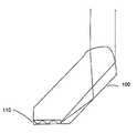
- FIG. 3is schematic diagram of one embodiment of a prism having a bottom portion that includes a waveguide.
- FIG. 4is a schematic diagram that shows an example of a PLC die having a first probe region and a second probe region.
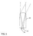
- FIG. 5is a schematic diagram that shows a cross-section view of an optical probe coupled to waveguides taken along their direction of propagation in the PLC.
- a method of testing a planar lightwave circuitis achieved by positioning an optical probe in a probe region over a waveguide.
- the probe regioncomprises a waveguide core layer that has either no upper cladding deposited yet, or has a very thin layer of upper cladding deposited.
- the probe regionhas had its upper cladding at least partially removed, e.g., by etching. The remaining upper cladding may be approximately 2 microns or less. In some cases part of the waveguide's core layer may also be removed.
- a second probemay be used in combination with the first probe to test the planar lightwave circuit by sending and receiving a light beam through the planar lightwave circuit.
- FIG. 2is a cross-sectional schematic diagram of an optical probe used to test a planar lightwave circuit (PLC) 30 .
- the PLC 30comprises a waveguide having a core layer 40 and lower cladding 52 .
- An optical probe 80is coupled to the PLC 30 in a probe region 60 having either a thin layer of upper cladding 50 or no upper cladding over the waveguide core.
- the probe region 60may include approximately 1–2 microns of upper cladding 50 over the waveguide core 40 . However, if reducing optical loss is important, a thicker upper cladding 50 may be employed.
- the optical probe 80is a prism having a rounded top 82 that serves as a lens to direct light incident upon the optical probe's upper surface to be focused toward the bottom portion of the optical probe 80 .
- the probe's upper surfacemay be either the complete focusing optics or a part of the focusing optics used to couple light between the probe and light source and/or detector.
- the optical probe 80is made of a material harder than that of which it will probe, so that the optical probe will not be scratched during its usage, and can be re-used on other PLCs.
- the optical probehas a slightly higher index of refraction than the waveguide for which it will probe.
- a high density glass or sapphiremay be used to probe a silica waveguide, and lithium niobate (LiNbO 3 ) or rutile may be suitable for probing a silicon nitride waveguide.
- the angle of the probe 30 and the probe's index of refractionare selected to match the guided mode of the waveguide of the PLC 30 . Different probes may be used for different waveguides.
- a second optical probe 90is coupled to a second probe region 92 .
- the second optical probe 90may be used in combination with the first optical probe 80 to test a waveguide in the PLC 30 .
- a light sourceis coupled to the first optical probe 80
- a photodetectoris coupled to the second optical probe 90 . If the waveguide is working properly the detector will detect light being emitted through the PLC 30 .
- An optical index-matching fluid 70may optionally be used in the interface between the PLC and the optical probes 80 , 90 to improve optical coupling.
- FIG. 3is schematic diagram of one embodiment of a prism 100 having a bottom portion that includes an integrated waveguide 110 .
- the waveguide 110may be diffused into the prism from the bottom, created by ion exchange or ion implantation, or may be deposited, e.g., by applying a chemical vapor deposition (CVD) technique.
- the integrated waveguide 110has a slightly higher refractive index than the rest of the probe, and is not uniform over the entire bottom portion of the prism 100 . Instead, the waveguide 110 has either an abrupt end, a graded end such as that of a diffused waveguide, or the waveguide 110 may have a grating.
- the waveguide 110should have a slightly higher index of refraction than the waveguide for which it will probe, and the waveguide 110 should facilitate a phase velocity that closely matches that of the PLC waveguide.
- the closeness of the matchdepends on the remaining thickness of the upper cladding; the smaller the upper cladding thickness, the less accurate a match is needed.
- the integrated waveguide 110allows for better coupling of the guided mode of the prism with that of the waveguide of the PLC.
- FIG. 4is a schematic diagram that shows an example of a PLC die 200 having a first probe region 210 and a second probe region 212 .
- the optical probesare removed from the PLC die 200 .
- one or more of the probe regions, such as probe region 210are removed from the PLC die 200 by slicing the die, e.g., along line 220 .
- the probe regionsare not removed; however, they may be filled with optical index-matching fluid to reduce optical losses in the PLC.
- FIG. 5is a schematic diagram that shows a cross-section view of an optical probe 300 coupled to waveguides 310 , 320 taken along their direction of propagation in the PLC.
- FIG. 5illustrates that an optical probe 300 can be coupled to more than one waveguide without moving the optical probe. If a light source is coupled to the optical probe, then the light can be directed to either of the waveguides 310 , 320 depending on the angle of incidence of the light into the optical probe. Alternatively, if a photodetector is coupled to the optical probe, then depending on the angle of the photodetector to the optical probe, light can be detected from either of the waveguides 310 , 320 .
- Multiple waveguidesmay be integrated into the optical probe similar to the integrated waveguide 110 of FIG. 2 to improve coupling to the waveguides 310 , 320 .
- a segmented optical probei.e., a probe having a top surface with several focuses, may be used. This allows coupling to multiple waveguides at the same time.
- the optical probemay also comprise a microlens array.
- this technologycan be used for fault isolation or intermediate device debugging capabilities. It can be applied to a whole wafer as well as previously diced and possibly fiber interfaced PLCs if they are found non-optimal in performance.
- One or more probes with detection and/or transmission capabilitymay be coupled at intermediate positions within the PLC (which would be inaccessible by conventional methods) to measure characteristics of PLC subunits and hence determine the local cause of observed effects for debug, fault isolation, and performance enhancement purposes.
- the optical probesmay be used with a moderately thick upper cladding. In this case, once the optical probe is removed, the transmission in the PLC is normal, and no loss is due to the temporary placement of the optical probe from testing.
Landscapes
- Physics & Mathematics (AREA)
- General Physics & Mathematics (AREA)
- Optics & Photonics (AREA)
- Engineering & Computer Science (AREA)
- Microelectronics & Electronic Packaging (AREA)
- Optical Integrated Circuits (AREA)
Abstract
Description
1. Field of the Invention
The described invention relates to the field of optical circuits. In particular, the invention relates to an optical probe for testing an optical circuit.
2. Description of Related Art
Optical circuits include, but are not limited to, light sources, detectors and/or waveguides that provide such functions as splitting, coupling, combining, multiplexing, demultiplexing, and switching. Planar lightwave circuits (PLCs) are optical circuits that are manufactured and operate in the plane of a wafer. PLC technology is advantageous because it can be used to form many different types of optical devices, such as array waveguide grating (AWG) filters, optical add/drop (de)multiplexers, optical switches, monolithic, as well as hybrid opto-electronic integrated devices. Such devices formed with optical fibers would typically be much larger or would not be feasible at all. Further, PLC structures may be mass produced on a silicon wafer.
If the PLC works properly, then optical fibers are permanently attached to the PLC, and the PLC is put into a package. However, if the PLC does not work properly, the unit is discarded, and the time and effort to dice, fiber mount and to comprehensively test the device are wasted. Thus, a method of testing a planar lightwave circuit at the wafer level or before fiber attach is important.
A method of testing a planar lightwave circuit is achieved by positioning an optical probe in a probe region over a waveguide. In one embodiment, the probe region comprises a waveguide core layer that has either no upper cladding deposited yet, or has a very thin layer of upper cladding deposited. In another embodiment, the probe region has had its upper cladding at least partially removed, e.g., by etching. The remaining upper cladding may be approximately 2 microns or less. In some cases part of the waveguide's core layer may also be removed. A second probe may be used in combination with the first probe to test the planar lightwave circuit by sending and receiving a light beam through the planar lightwave circuit.
Anoptical probe 80 is coupled to thePLC 30 in aprobe region 60 having either a thin layer ofupper cladding 50 or no upper cladding over the waveguide core. In one embodiment, theprobe region 60 may include approximately 1–2 microns ofupper cladding 50 over thewaveguide core 40. However, if reducing optical loss is important, a thickerupper cladding 50 may be employed.
In one embodiment, theoptical probe 80 is a prism having arounded top 82 that serves as a lens to direct light incident upon the optical probe's upper surface to be focused toward the bottom portion of theoptical probe 80. The probe's upper surface may be either the complete focusing optics or a part of the focusing optics used to couple light between the probe and light source and/or detector. Preferably theoptical probe 80 is made of a material harder than that of which it will probe, so that the optical probe will not be scratched during its usage, and can be re-used on other PLCs.
The optical probe has a slightly higher index of refraction than the waveguide for which it will probe. For example, a high density glass or sapphire may be used to probe a silica waveguide, and lithium niobate (LiNbO3) or rutile may be suitable for probing a silicon nitride waveguide. The angle of theprobe 30 and the probe's index of refraction are selected to match the guided mode of the waveguide of thePLC 30. Different probes may be used for different waveguides.
In one embodiment, a secondoptical probe 90 is coupled to asecond probe region 92. The secondoptical probe 90 may be used in combination with the firstoptical probe 80 to test a waveguide in thePLC 30. In one embodiment, a light source is coupled to the firstoptical probe 80, and a photodetector is coupled to the secondoptical probe 90. If the waveguide is working properly the detector will detect light being emitted through thePLC 30. An optical index-matchingfluid 70 may optionally be used in the interface between the PLC and theoptical probes
Multiple waveguides may be integrated into the optical probe similar to theintegrated waveguide 110 ofFIG. 2 to improve coupling to thewaveguides
A segmented optical probe, i.e., a probe having a top surface with several focuses, may be used. This allows coupling to multiple waveguides at the same time. The optical probe may also comprise a microlens array.
In addition to the testing methods previously mentioned, this technology can be used for fault isolation or intermediate device debugging capabilities. It can be applied to a whole wafer as well as previously diced and possibly fiber interfaced PLCs if they are found non-optimal in performance. One or more probes with detection and/or transmission capability may be coupled at intermediate positions within the PLC (which would be inaccessible by conventional methods) to measure characteristics of PLC subunits and hence determine the local cause of observed effects for debug, fault isolation, and performance enhancement purposes. In one embodiment, the optical probes may be used with a moderately thick upper cladding. In this case, once the optical probe is removed, the transmission in the PLC is normal, and no loss is due to the temporary placement of the optical probe from testing.
Thus, a method and apparatus for testing a planar lightwave circuit using an optical probe is disclosed. However, the specific embodiments and methods described herein are merely illustrative. Numerous modifications in form and detail may be made without departing from the scope of the invention as claimed below. The invention is limited only by the scope of the appended claims.
Claims (15)
1. An optical probe comprising:
a prism having a rounded top; and
a first waveguide in or on a bottom portion of the prism, the rounded top to focus light entering the prism into the first waveguide,
wherein the first waveguide comprises an integrated waveguide.
2. The optical probe ofclaim 1 , wherein the light entering the rounded top is capable of being redirected approximately 90 degrees by the prism and the first waveguide.
3. An optical probe comprising:
a prism having a rounded top;
a first waveguide in or on a bottom portion of the prism, the rounded top to focus light entering the prism into the first waveguide; and
a second waveguide in or on the bottom portion of the prism, wherein the rounded top constitutes more than one focus to couple light into the first waveguide and the second waveguide.
4. An optical probe comprising:
a prism having a rounded top; and
a first waveguide in or on a bottom portion of the prism, the rounded top to focus light entering the prism into the first waveguide,
wherein the rounded top comprises a microlens array.
5. A method of making an optical probe, the method comprising:
forming a lens surface on a prism; and
forming a waveguide in or on a bottom portion of the prism.
6. The method ofclaim 5 , wherein the waveguide is formed by diffusion or ion exchange.
7. The method ofclaim 5 , wherein the waveguide is formed by ion implantation.
8. The method ofclaim 5 , wherein the waveguide is formed by deposition.
9. The method ofclaim 5 , further comprising:
forming a second waveguide in or on the bottom portion of the prism.
10. The method ofclaim 5 , wherein forming the lens surface on the prism further comprises
forming a lens surface having more than one focus.
11. The method ofclaim 5 , wherein forming the lens surface on the prism further comprises
forming a lens surface having a microlens array.
12. An optical probe comprising:
a prism having a rounded top; and
a first waveguide in or on a bottom portion of the prism, the rounded top to focus light entering the prism into the first waveguide,
wherein the first waveguide has an end selected from an abrupt end and a graded end.
13. The optical probe ofclaim 12 , wherein the prism is at least partially made of sapphire, high density glass, LiNbO3, or rutile.
14. An optical probe comprising:
a prism having a rounded top; and
a first waveguide in or on a bottom portion of the prism, the rounded top to focus light entering the prism into the first waveguide,
wherein the first waveguide has a higher index of refraction than the prism.
15. The method ofclaim 5 , wherein the waveguide is formed within the prism.
Priority Applications (1)
| Application Number | Priority Date | Filing Date | Title |
|---|---|---|---|
| US10/040,398US7020363B2 (en) | 2001-12-28 | 2001-12-28 | Optical probe for wafer testing |
Applications Claiming Priority (1)
| Application Number | Priority Date | Filing Date | Title |
|---|---|---|---|
| US10/040,398US7020363B2 (en) | 2001-12-28 | 2001-12-28 | Optical probe for wafer testing |
Publications (2)
| Publication Number | Publication Date |
|---|---|
| US20030123793A1 US20030123793A1 (en) | 2003-07-03 |
| US7020363B2true US7020363B2 (en) | 2006-03-28 |
Family
ID=21910765
Family Applications (1)
| Application Number | Title | Priority Date | Filing Date |
|---|---|---|---|
| US10/040,398Expired - Fee RelatedUS7020363B2 (en) | 2001-12-28 | 2001-12-28 | Optical probe for wafer testing |
Country Status (1)
| Country | Link |
|---|---|
| US (1) | US7020363B2 (en) |
Cited By (59)
| Publication number | Priority date | Publication date | Assignee | Title |
|---|---|---|---|---|
| US20040093716A1 (en)* | 1998-07-14 | 2004-05-20 | Reed Gleason | Membrane probing system |
| US20050122125A1 (en)* | 2002-12-13 | 2005-06-09 | Cascade Microtech, Inc. | Guarded tub enclosure |
| US20060164112A1 (en)* | 1997-06-10 | 2006-07-27 | Cascade Microtech, Inc. | Low-current pogo probe card |
| US20060170439A1 (en)* | 2003-05-23 | 2006-08-03 | Cascade Microtech, Inc. | Probe for testing a device under test |
| US20060202708A1 (en)* | 1995-12-01 | 2006-09-14 | Cascade Microtech, Inc. | Low-current probe card |
| US20060208748A1 (en)* | 1997-05-28 | 2006-09-21 | Cascade Microtech, Inc. | Probe holder for testing of a test device |
| US20060214676A1 (en)* | 1996-08-08 | 2006-09-28 | Cascade Microtech, Inc. | Membrane probing system with local contact scrub |
| US20060214677A1 (en)* | 2002-11-13 | 2006-09-28 | Cascade Microtech, Inc. | Probe for combined signals |
| US20060229279A1 (en)* | 2002-03-07 | 2006-10-12 | Hartell Mark G | Artemisinins with improved stability and bioavailability for therapeutic drug development and application |
| US20060267610A1 (en)* | 1997-06-06 | 2006-11-30 | Peters Ron A | Probe station having multiple enclosures |
| US7176705B2 (en) | 2004-06-07 | 2007-02-13 | Cascade Microtech, Inc. | Thermal optical chuck |
| US7178236B2 (en) | 1999-06-04 | 2007-02-20 | Cascade Microtech, Inc. | Method for constructing a membrane probe using a depression |
| US7187188B2 (en) | 2003-12-24 | 2007-03-06 | Cascade Microtech, Inc. | Chuck with integrated wafer support |
| US7221172B2 (en) | 2003-05-06 | 2007-05-22 | Cascade Microtech, Inc. | Switched suspended conductor and connection |
| US7250626B2 (en) | 2003-10-22 | 2007-07-31 | Cascade Microtech, Inc. | Probe testing structure |
| US7250779B2 (en) | 2002-11-25 | 2007-07-31 | Cascade Microtech, Inc. | Probe station with low inductance path |
| US7268533B2 (en) | 2001-08-31 | 2007-09-11 | Cascade Microtech, Inc. | Optical testing device |
| US7292057B2 (en) | 1999-06-30 | 2007-11-06 | Cascade Microtech, Inc. | Probe station thermal chuck with shielding for capacitive current |
| US7295025B2 (en) | 2002-11-08 | 2007-11-13 | Cascade Microtech, Inc. | Probe station with low noise characteristics |
| US20070294047A1 (en)* | 2005-06-11 | 2007-12-20 | Leonard Hayden | Calibration system |
| US20080003842A1 (en)* | 2006-06-30 | 2008-01-03 | Sanjay Dabral | Circuit board-to-circuit board connectors having electro-optic modulators |
| US7321233B2 (en) | 1995-04-14 | 2008-01-22 | Cascade Microtech, Inc. | System for evaluating probing networks |
| US7330023B2 (en) | 1992-06-11 | 2008-02-12 | Cascade Microtech, Inc. | Wafer probe station having a skirting component |
| US7330041B2 (en) | 2004-06-14 | 2008-02-12 | Cascade Microtech, Inc. | Localizing a temperature of a device for testing |
| US7348787B2 (en) | 1992-06-11 | 2008-03-25 | Cascade Microtech, Inc. | Wafer probe station having environment control enclosure |
| US7352168B2 (en) | 2000-09-05 | 2008-04-01 | Cascade Microtech, Inc. | Chuck for holding a device under test |
| US7355420B2 (en) | 2001-08-21 | 2008-04-08 | Cascade Microtech, Inc. | Membrane probing system |
| US7368925B2 (en) | 2002-01-25 | 2008-05-06 | Cascade Microtech, Inc. | Probe station with two platens |
| US7368927B2 (en) | 2004-07-07 | 2008-05-06 | Cascade Microtech, Inc. | Probe head having a membrane suspended probe |
| US20080122463A1 (en)* | 2006-06-30 | 2008-05-29 | Sanjay Dabral | Testing microelectronic devices using electro-optic modulator probes |
| US7403028B2 (en) | 2006-06-12 | 2008-07-22 | Cascade Microtech, Inc. | Test structure and probe for differential signals |
| US7403025B2 (en) | 2000-02-25 | 2008-07-22 | Cascade Microtech, Inc. | Membrane probing system |
| US7420381B2 (en) | 2004-09-13 | 2008-09-02 | Cascade Microtech, Inc. | Double sided probing structures |
| US7427868B2 (en) | 2003-12-24 | 2008-09-23 | Cascade Microtech, Inc. | Active wafer probe |
| US7436194B2 (en) | 2002-05-23 | 2008-10-14 | Cascade Microtech, Inc. | Shielded probe with low contact resistance for testing a device under test |
| US7443186B2 (en) | 2006-06-12 | 2008-10-28 | Cascade Microtech, Inc. | On-wafer test structures for differential signals |
| US7449899B2 (en) | 2005-06-08 | 2008-11-11 | Cascade Microtech, Inc. | Probe for high frequency signals |
| US7456646B2 (en) | 2000-12-04 | 2008-11-25 | Cascade Microtech, Inc. | Wafer probe |
| US7492172B2 (en) | 2003-05-23 | 2009-02-17 | Cascade Microtech, Inc. | Chuck for holding a device under test |
| US7535247B2 (en) | 2005-01-31 | 2009-05-19 | Cascade Microtech, Inc. | Interface for testing semiconductors |
| US7554322B2 (en) | 2000-09-05 | 2009-06-30 | Cascade Microtech, Inc. | Probe station |
| US7609077B2 (en) | 2006-06-09 | 2009-10-27 | Cascade Microtech, Inc. | Differential signal probe with integral balun |
| US7619419B2 (en) | 2005-06-13 | 2009-11-17 | Cascade Microtech, Inc. | Wideband active-passive differential signal probe |
| US7656172B2 (en) | 2005-01-31 | 2010-02-02 | Cascade Microtech, Inc. | System for testing semiconductors |
| US7723999B2 (en) | 2006-06-12 | 2010-05-25 | Cascade Microtech, Inc. | Calibration structures for differential signal probing |
| US7764072B2 (en) | 2006-06-12 | 2010-07-27 | Cascade Microtech, Inc. | Differential signal probing system |
| US7876114B2 (en) | 2007-08-08 | 2011-01-25 | Cascade Microtech, Inc. | Differential waveguide probe |
| US7888957B2 (en) | 2008-10-06 | 2011-02-15 | Cascade Microtech, Inc. | Probing apparatus with impedance optimized interface |
| US8319503B2 (en) | 2008-11-24 | 2012-11-27 | Cascade Microtech, Inc. | Test apparatus for measuring a characteristic of a device under test |
| US8410806B2 (en) | 2008-11-21 | 2013-04-02 | Cascade Microtech, Inc. | Replaceable coupon for a probing apparatus |
| US9094135B2 (en) | 2013-06-10 | 2015-07-28 | Freescale Semiconductor, Inc. | Die stack with optical TSVs |
| US9091820B2 (en) | 2013-06-10 | 2015-07-28 | Freescale Semiconductor, Inc. | Communication system die stack |
| US9261556B2 (en) | 2013-06-10 | 2016-02-16 | Freescale Semiconductor, Inc. | Optical wafer and die probe testing |
| US9435952B2 (en) | 2013-06-10 | 2016-09-06 | Freescale Semiconductor, Inc. | Integration of a MEMS beam with optical waveguide and deflection in two dimensions |
| US9442254B2 (en) | 2013-06-10 | 2016-09-13 | Freescale Semiconductor, Inc. | Method and apparatus for beam control with optical MEMS beam waveguide |
| US9766409B2 (en) | 2013-06-10 | 2017-09-19 | Nxp Usa, Inc. | Optical redundancy |
| US9810843B2 (en) | 2013-06-10 | 2017-11-07 | Nxp Usa, Inc. | Optical backplane mirror |
| US10230458B2 (en) | 2013-06-10 | 2019-03-12 | Nxp Usa, Inc. | Optical die test interface with separate voltages for adjacent electrodes |
| US10914897B2 (en) | 2018-12-12 | 2021-02-09 | Globalfoundries Inc. | Optical on-wafer probing with v-groove couplers |
Families Citing this family (11)
| Publication number | Priority date | Publication date | Assignee | Title |
|---|---|---|---|---|
| US7116851B2 (en) | 2001-10-09 | 2006-10-03 | Infinera Corporation | Optical signal receiver, an associated photonic integrated circuit (RxPIC), and method improving performance |
| US7020363B2 (en)* | 2001-12-28 | 2006-03-28 | Intel Corporation | Optical probe for wafer testing |
| US6909830B2 (en)* | 2002-07-16 | 2005-06-21 | Enablence Holdings Llc | Method and apparatus for on-wafer testing of an individual optical chip |
| US6925238B2 (en)* | 2002-07-16 | 2005-08-02 | Enablence Holdings Llc | Method and apparatus for on-wafer testing of an individual optical chip |
| KR101141014B1 (en)* | 2004-03-08 | 2012-05-02 | 시옵티컬 인코포레이티드 | Wafer-level opto-electronic testing apparatus and method |
| US9759634B2 (en) | 2015-09-14 | 2017-09-12 | Seagate Technology Llc | Coupling loss evaluation |
| US9791346B1 (en)* | 2016-04-20 | 2017-10-17 | Stmicroelectronics Sa | Semiconductor device and wafer with reference circuit and related methods |
| US10012798B2 (en)* | 2016-06-30 | 2018-07-03 | International Business Machines Corporation | Sacrificial coupler for testing V-grooved integrated circuits |
| JP2019197126A (en)* | 2018-05-09 | 2019-11-14 | 日本電信電話株式会社 | Optical device and optical coupling method |
| CN110941045A (en)* | 2018-05-18 | 2020-03-31 | 博创科技股份有限公司 | Optical wafer and chip with reflector function for wafer level test |
| DE102021117664A1 (en)* | 2021-07-08 | 2023-01-12 | Ingun Prüfmittelbau Gmbh | Test device for high-frequency applications |
Citations (2)
| Publication number | Priority date | Publication date | Assignee | Title |
|---|---|---|---|---|
| US20030123793A1 (en)* | 2001-12-28 | 2003-07-03 | Kjetil Johannessen | Optical probe for wafer testing |
| US6687010B1 (en)* | 1999-09-09 | 2004-02-03 | Olympus Corporation | Rapid depth scanning optical imaging device |
- 2001
- 2001-12-28USUS10/040,398patent/US7020363B2/ennot_activeExpired - Fee Related
Patent Citations (2)
| Publication number | Priority date | Publication date | Assignee | Title |
|---|---|---|---|---|
| US6687010B1 (en)* | 1999-09-09 | 2004-02-03 | Olympus Corporation | Rapid depth scanning optical imaging device |
| US20030123793A1 (en)* | 2001-12-28 | 2003-07-03 | Kjetil Johannessen | Optical probe for wafer testing |
Cited By (120)
| Publication number | Priority date | Publication date | Assignee | Title |
|---|---|---|---|---|
| US7589518B2 (en) | 1992-06-11 | 2009-09-15 | Cascade Microtech, Inc. | Wafer probe station having a skirting component |
| US7330023B2 (en) | 1992-06-11 | 2008-02-12 | Cascade Microtech, Inc. | Wafer probe station having a skirting component |
| US7492147B2 (en) | 1992-06-11 | 2009-02-17 | Cascade Microtech, Inc. | Wafer probe station having a skirting component |
| US7595632B2 (en) | 1992-06-11 | 2009-09-29 | Cascade Microtech, Inc. | Wafer probe station having environment control enclosure |
| US7348787B2 (en) | 1992-06-11 | 2008-03-25 | Cascade Microtech, Inc. | Wafer probe station having environment control enclosure |
| US7321233B2 (en) | 1995-04-14 | 2008-01-22 | Cascade Microtech, Inc. | System for evaluating probing networks |
| US20060202708A1 (en)* | 1995-12-01 | 2006-09-14 | Cascade Microtech, Inc. | Low-current probe card |
| US20060214676A1 (en)* | 1996-08-08 | 2006-09-28 | Cascade Microtech, Inc. | Membrane probing system with local contact scrub |
| US20070296431A1 (en)* | 1996-08-08 | 2007-12-27 | Cascade Microtech, Inc. | Membrane probing system with local contact scrub |
| US7550983B2 (en) | 1996-08-08 | 2009-06-23 | Cascade Microtech, Inc. | Membrane probing system with local contact scrub |
| US7893704B2 (en) | 1996-08-08 | 2011-02-22 | Cascade Microtech, Inc. | Membrane probing structure with laterally scrubbing contacts |
| US7541821B2 (en) | 1996-08-08 | 2009-06-02 | Cascade Microtech, Inc. | Membrane probing system with local contact scrub |
| US7221174B2 (en) | 1997-05-28 | 2007-05-22 | Cascade Microtech, Inc. | Probe holder for testing of a test device |
| US20060208748A1 (en)* | 1997-05-28 | 2006-09-21 | Cascade Microtech, Inc. | Probe holder for testing of a test device |
| US7504842B2 (en) | 1997-05-28 | 2009-03-17 | Cascade Microtech, Inc. | Probe holder for testing of a test device |
| US7436170B2 (en) | 1997-06-06 | 2008-10-14 | Cascade Microtech, Inc. | Probe station having multiple enclosures |
| US20060267610A1 (en)* | 1997-06-06 | 2006-11-30 | Peters Ron A | Probe station having multiple enclosures |
| US7626379B2 (en) | 1997-06-06 | 2009-12-01 | Cascade Microtech, Inc. | Probe station having multiple enclosures |
| US7250752B2 (en) | 1997-06-06 | 2007-07-31 | Cascade Microtech, Inc. | Probe station having multiple enclosures |
| US20060164112A1 (en)* | 1997-06-10 | 2006-07-27 | Cascade Microtech, Inc. | Low-current pogo probe card |
| US7400155B2 (en) | 1998-07-14 | 2008-07-15 | Cascade Microtech, Inc. | Membrane probing system |
| US7681312B2 (en) | 1998-07-14 | 2010-03-23 | Cascade Microtech, Inc. | Membrane probing system |
| US7266889B2 (en) | 1998-07-14 | 2007-09-11 | Cascade Microtech, Inc. | Membrane probing system |
| US8451017B2 (en) | 1998-07-14 | 2013-05-28 | Cascade Microtech, Inc. | Membrane probing method using improved contact |
| US7761986B2 (en) | 1998-07-14 | 2010-07-27 | Cascade Microtech, Inc. | Membrane probing method using improved contact |
| US20040093716A1 (en)* | 1998-07-14 | 2004-05-20 | Reed Gleason | Membrane probing system |
| US7178236B2 (en) | 1999-06-04 | 2007-02-20 | Cascade Microtech, Inc. | Method for constructing a membrane probe using a depression |
| US20070074392A1 (en)* | 1999-06-04 | 2007-04-05 | Cascade Microtech, Inc. | Membrane probing system |
| US7533462B2 (en) | 1999-06-04 | 2009-05-19 | Cascade Microtech, Inc. | Method of constructing a membrane probe |
| US7292057B2 (en) | 1999-06-30 | 2007-11-06 | Cascade Microtech, Inc. | Probe station thermal chuck with shielding for capacitive current |
| US7616017B2 (en) | 1999-06-30 | 2009-11-10 | Cascade Microtech, Inc. | Probe station thermal chuck with shielding for capacitive current |
| US7403025B2 (en) | 2000-02-25 | 2008-07-22 | Cascade Microtech, Inc. | Membrane probing system |
| US7423419B2 (en) | 2000-09-05 | 2008-09-09 | Cascade Microtech, Inc. | Chuck for holding a device under test |
| US7501810B2 (en) | 2000-09-05 | 2009-03-10 | Cascade Microtech, Inc. | Chuck for holding a device under test |
| US7352168B2 (en) | 2000-09-05 | 2008-04-01 | Cascade Microtech, Inc. | Chuck for holding a device under test |
| US7514915B2 (en) | 2000-09-05 | 2009-04-07 | Cascade Microtech, Inc. | Chuck for holding a device under test |
| US7554322B2 (en) | 2000-09-05 | 2009-06-30 | Cascade Microtech, Inc. | Probe station |
| US7518358B2 (en) | 2000-09-05 | 2009-04-14 | Cascade Microtech, Inc. | Chuck for holding a device under test |
| US7969173B2 (en) | 2000-09-05 | 2011-06-28 | Cascade Microtech, Inc. | Chuck for holding a device under test |
| US7688062B2 (en) | 2000-09-05 | 2010-03-30 | Cascade Microtech, Inc. | Probe station |
| US7688097B2 (en) | 2000-12-04 | 2010-03-30 | Cascade Microtech, Inc. | Wafer probe |
| US7456646B2 (en) | 2000-12-04 | 2008-11-25 | Cascade Microtech, Inc. | Wafer probe |
| US7495461B2 (en) | 2000-12-04 | 2009-02-24 | Cascade Microtech, Inc. | Wafer probe |
| US7761983B2 (en) | 2000-12-04 | 2010-07-27 | Cascade Microtech, Inc. | Method of assembling a wafer probe |
| US7355420B2 (en) | 2001-08-21 | 2008-04-08 | Cascade Microtech, Inc. | Membrane probing system |
| US20080111571A1 (en)* | 2001-08-21 | 2008-05-15 | Cascade Microtech, Inc. | Membrane probing system |
| US7492175B2 (en) | 2001-08-21 | 2009-02-17 | Cascade Microtech, Inc. | Membrane probing system |
| US7268533B2 (en) | 2001-08-31 | 2007-09-11 | Cascade Microtech, Inc. | Optical testing device |
| US7368925B2 (en) | 2002-01-25 | 2008-05-06 | Cascade Microtech, Inc. | Probe station with two platens |
| US20060229279A1 (en)* | 2002-03-07 | 2006-10-12 | Hartell Mark G | Artemisinins with improved stability and bioavailability for therapeutic drug development and application |
| US7436194B2 (en) | 2002-05-23 | 2008-10-14 | Cascade Microtech, Inc. | Shielded probe with low contact resistance for testing a device under test |
| US7518387B2 (en) | 2002-05-23 | 2009-04-14 | Cascade Microtech, Inc. | Shielded probe for testing a device under test |
| US7489149B2 (en) | 2002-05-23 | 2009-02-10 | Cascade Microtech, Inc. | Shielded probe for testing a device under test |
| US7482823B2 (en) | 2002-05-23 | 2009-01-27 | Cascade Microtech, Inc. | Shielded probe for testing a device under test |
| US7550984B2 (en) | 2002-11-08 | 2009-06-23 | Cascade Microtech, Inc. | Probe station with low noise characteristics |
| US7295025B2 (en) | 2002-11-08 | 2007-11-13 | Cascade Microtech, Inc. | Probe station with low noise characteristics |
| US20060214677A1 (en)* | 2002-11-13 | 2006-09-28 | Cascade Microtech, Inc. | Probe for combined signals |
| US7453276B2 (en) | 2002-11-13 | 2008-11-18 | Cascade Microtech, Inc. | Probe for combined signals |
| US7205784B2 (en) | 2002-11-13 | 2007-04-17 | Cascade Microtech, Inc. | Probe for combined signals |
| US7417446B2 (en) | 2002-11-13 | 2008-08-26 | Cascade Microtech, Inc. | Probe for combined signals |
| US7285969B2 (en) | 2002-11-13 | 2007-10-23 | Cascade Microtech, Inc. | Probe for combined signals |
| US7498828B2 (en) | 2002-11-25 | 2009-03-03 | Cascade Microtech, Inc. | Probe station with low inductance path |
| US7250779B2 (en) | 2002-11-25 | 2007-07-31 | Cascade Microtech, Inc. | Probe station with low inductance path |
| US7221146B2 (en) | 2002-12-13 | 2007-05-22 | Cascade Microtech, Inc. | Guarded tub enclosure |
| US7639003B2 (en) | 2002-12-13 | 2009-12-29 | Cascade Microtech, Inc. | Guarded tub enclosure |
| US20050122125A1 (en)* | 2002-12-13 | 2005-06-09 | Cascade Microtech, Inc. | Guarded tub enclosure |
| US7221172B2 (en) | 2003-05-06 | 2007-05-22 | Cascade Microtech, Inc. | Switched suspended conductor and connection |
| US7468609B2 (en) | 2003-05-06 | 2008-12-23 | Cascade Microtech, Inc. | Switched suspended conductor and connection |
| US7898273B2 (en) | 2003-05-23 | 2011-03-01 | Cascade Microtech, Inc. | Probe for testing a device under test |
| US20060170439A1 (en)* | 2003-05-23 | 2006-08-03 | Cascade Microtech, Inc. | Probe for testing a device under test |
| US7271603B2 (en) | 2003-05-23 | 2007-09-18 | Cascade Microtech, Inc. | Shielded probe for testing a device under test |
| US7876115B2 (en) | 2003-05-23 | 2011-01-25 | Cascade Microtech, Inc. | Chuck for holding a device under test |
| US7501842B2 (en) | 2003-05-23 | 2009-03-10 | Cascade Microtech, Inc. | Shielded probe for testing a device under test |
| US7492172B2 (en) | 2003-05-23 | 2009-02-17 | Cascade Microtech, Inc. | Chuck for holding a device under test |
| US7498829B2 (en) | 2003-05-23 | 2009-03-03 | Cascade Microtech, Inc. | Shielded probe for testing a device under test |
| US8069491B2 (en) | 2003-10-22 | 2011-11-29 | Cascade Microtech, Inc. | Probe testing structure |
| US7250626B2 (en) | 2003-10-22 | 2007-07-31 | Cascade Microtech, Inc. | Probe testing structure |
| US7362115B2 (en) | 2003-12-24 | 2008-04-22 | Cascade Microtech, Inc. | Chuck with integrated wafer support |
| US7759953B2 (en) | 2003-12-24 | 2010-07-20 | Cascade Microtech, Inc. | Active wafer probe |
| US7688091B2 (en) | 2003-12-24 | 2010-03-30 | Cascade Microtech, Inc. | Chuck with integrated wafer support |
| US7187188B2 (en) | 2003-12-24 | 2007-03-06 | Cascade Microtech, Inc. | Chuck with integrated wafer support |
| US7427868B2 (en) | 2003-12-24 | 2008-09-23 | Cascade Microtech, Inc. | Active wafer probe |
| US7176705B2 (en) | 2004-06-07 | 2007-02-13 | Cascade Microtech, Inc. | Thermal optical chuck |
| US7504823B2 (en) | 2004-06-07 | 2009-03-17 | Cascade Microtech, Inc. | Thermal optical chuck |
| US7330041B2 (en) | 2004-06-14 | 2008-02-12 | Cascade Microtech, Inc. | Localizing a temperature of a device for testing |
| US7368927B2 (en) | 2004-07-07 | 2008-05-06 | Cascade Microtech, Inc. | Probe head having a membrane suspended probe |
| US7514944B2 (en) | 2004-07-07 | 2009-04-07 | Cascade Microtech, Inc. | Probe head having a membrane suspended probe |
| US7420381B2 (en) | 2004-09-13 | 2008-09-02 | Cascade Microtech, Inc. | Double sided probing structures |
| US8013623B2 (en) | 2004-09-13 | 2011-09-06 | Cascade Microtech, Inc. | Double sided probing structures |
| US7656172B2 (en) | 2005-01-31 | 2010-02-02 | Cascade Microtech, Inc. | System for testing semiconductors |
| US7940069B2 (en) | 2005-01-31 | 2011-05-10 | Cascade Microtech, Inc. | System for testing semiconductors |
| US7535247B2 (en) | 2005-01-31 | 2009-05-19 | Cascade Microtech, Inc. | Interface for testing semiconductors |
| US7898281B2 (en) | 2005-01-31 | 2011-03-01 | Cascade Mircotech, Inc. | Interface for testing semiconductors |
| US7449899B2 (en) | 2005-06-08 | 2008-11-11 | Cascade Microtech, Inc. | Probe for high frequency signals |
| US20070294047A1 (en)* | 2005-06-11 | 2007-12-20 | Leonard Hayden | Calibration system |
| US7619419B2 (en) | 2005-06-13 | 2009-11-17 | Cascade Microtech, Inc. | Wideband active-passive differential signal probe |
| US7609077B2 (en) | 2006-06-09 | 2009-10-27 | Cascade Microtech, Inc. | Differential signal probe with integral balun |
| US7723999B2 (en) | 2006-06-12 | 2010-05-25 | Cascade Microtech, Inc. | Calibration structures for differential signal probing |
| US7750652B2 (en) | 2006-06-12 | 2010-07-06 | Cascade Microtech, Inc. | Test structure and probe for differential signals |
| US7764072B2 (en) | 2006-06-12 | 2010-07-27 | Cascade Microtech, Inc. | Differential signal probing system |
| US7403028B2 (en) | 2006-06-12 | 2008-07-22 | Cascade Microtech, Inc. | Test structure and probe for differential signals |
| US7443186B2 (en) | 2006-06-12 | 2008-10-28 | Cascade Microtech, Inc. | On-wafer test structures for differential signals |
| US20080122463A1 (en)* | 2006-06-30 | 2008-05-29 | Sanjay Dabral | Testing microelectronic devices using electro-optic modulator probes |
| US7525723B2 (en) | 2006-06-30 | 2009-04-28 | Intel Corporation | Circuit board-to-circuit board connectors having electro-optic modulators |
| US20080003842A1 (en)* | 2006-06-30 | 2008-01-03 | Sanjay Dabral | Circuit board-to-circuit board connectors having electro-optic modulators |
| US7876114B2 (en) | 2007-08-08 | 2011-01-25 | Cascade Microtech, Inc. | Differential waveguide probe |
| US7888957B2 (en) | 2008-10-06 | 2011-02-15 | Cascade Microtech, Inc. | Probing apparatus with impedance optimized interface |
| US8410806B2 (en) | 2008-11-21 | 2013-04-02 | Cascade Microtech, Inc. | Replaceable coupon for a probing apparatus |
| US10267848B2 (en) | 2008-11-21 | 2019-04-23 | Formfactor Beaverton, Inc. | Method of electrically contacting a bond pad of a device under test with a probe |
| US9429638B2 (en) | 2008-11-21 | 2016-08-30 | Cascade Microtech, Inc. | Method of replacing an existing contact of a wafer probing assembly |
| US8319503B2 (en) | 2008-11-24 | 2012-11-27 | Cascade Microtech, Inc. | Test apparatus for measuring a characteristic of a device under test |
| US9261556B2 (en) | 2013-06-10 | 2016-02-16 | Freescale Semiconductor, Inc. | Optical wafer and die probe testing |
| US9091820B2 (en) | 2013-06-10 | 2015-07-28 | Freescale Semiconductor, Inc. | Communication system die stack |
| US9435952B2 (en) | 2013-06-10 | 2016-09-06 | Freescale Semiconductor, Inc. | Integration of a MEMS beam with optical waveguide and deflection in two dimensions |
| US9442254B2 (en) | 2013-06-10 | 2016-09-13 | Freescale Semiconductor, Inc. | Method and apparatus for beam control with optical MEMS beam waveguide |
| US9766409B2 (en) | 2013-06-10 | 2017-09-19 | Nxp Usa, Inc. | Optical redundancy |
| US9810843B2 (en) | 2013-06-10 | 2017-11-07 | Nxp Usa, Inc. | Optical backplane mirror |
| US10230458B2 (en) | 2013-06-10 | 2019-03-12 | Nxp Usa, Inc. | Optical die test interface with separate voltages for adjacent electrodes |
| US9094135B2 (en) | 2013-06-10 | 2015-07-28 | Freescale Semiconductor, Inc. | Die stack with optical TSVs |
| US10914897B2 (en) | 2018-12-12 | 2021-02-09 | Globalfoundries Inc. | Optical on-wafer probing with v-groove couplers |
Also Published As
| Publication number | Publication date |
|---|---|
| US20030123793A1 (en) | 2003-07-03 |
Similar Documents
| Publication | Publication Date | Title |
|---|---|---|
| US7020363B2 (en) | Optical probe for wafer testing | |
| JP6798996B2 (en) | Multiport optical probe for characterization and packaging of optical integrated circuits | |
| US7386197B2 (en) | Method and apparatus for wafer level testing of integrated optical waveguide circuits | |
| US6909830B2 (en) | Method and apparatus for on-wafer testing of an individual optical chip | |
| US6925238B2 (en) | Method and apparatus for on-wafer testing of an individual optical chip | |
| US10782342B2 (en) | Integrated optical probe card and system for batch testing of optical MEMS structures with in-plane optical axis using micro-optical bench components | |
| US20230376818A1 (en) | High Density Fiber Optic Packaging for Cryogenic Applications | |
| EP0747745A1 (en) | Self-aligned mechanical optical switch | |
| JP2007528129A (en) | Opto-electronic test apparatus and method at wafer level | |
| JP7080910B2 (en) | Test device and heterogeneous integrated structure | |
| CA2217688C (en) | Coupling of light into a monolithic waveguide device | |
| CN112924143B (en) | A photonic chip wafer level testing device and method | |
| US6947622B2 (en) | Wafer level testing of optical components | |
| US12287511B2 (en) | Managing characterization of optical couplers in an integrated circuit | |
| WO2022266760A1 (en) | Printed photonic component based photonic device probing and testing | |
| TW202526402A (en) | An optical probe and related methods | |
| Ngo et al. | Novel U-groove channel for self-alignment of optical fibers with optical quality end-polished silicon rib waveguides using wet chemical micromachining techniques | |
| Cho et al. | High speed optical signal distribution using fully embedded thin film MSM photodetectors in multimode interference couplers | |
| JPH10332969A (en) | Polarization detector |
Legal Events
| Date | Code | Title | Description |
|---|---|---|---|
| AS | Assignment | Owner name:INTEL CORPORATION, CALIFORNIA Free format text:ASSIGNMENT OF ASSIGNORS INTEREST;ASSIGNOR:JOHANNESSEN, KJETIL;REEL/FRAME:012751/0495 Effective date:20020227 | |
| REMI | Maintenance fee reminder mailed | ||
| LAPS | Lapse for failure to pay maintenance fees | ||
| STCH | Information on status: patent discontinuation | Free format text:PATENT EXPIRED DUE TO NONPAYMENT OF MAINTENANCE FEES UNDER 37 CFR 1.362 | |
| FP | Lapsed due to failure to pay maintenance fee | Effective date:20100328 |