US7020157B2 - Network address assignment in a passive optical network - Google Patents
Network address assignment in a passive optical networkDownload PDFInfo
- Publication number
- US7020157B2 US7020157B2US10/144,008US14400802AUS7020157B2US 7020157 B2US7020157 B2US 7020157B2US 14400802 AUS14400802 AUS 14400802AUS 7020157 B2US7020157 B2US 7020157B2
- Authority
- US
- United States
- Prior art keywords
- group
- network nodes
- network
- addresses
- dhcp
- Prior art date
- Legal status (The legal status is an assumption and is not a legal conclusion. Google has not performed a legal analysis and makes no representation as to the accuracy of the status listed.)
- Expired - Lifetime, expires
Links
Images


Classifications
- H—ELECTRICITY
- H04—ELECTRIC COMMUNICATION TECHNIQUE
- H04L—TRANSMISSION OF DIGITAL INFORMATION, e.g. TELEGRAPHIC COMMUNICATION
- H04L61/00—Network arrangements, protocols or services for addressing or naming
- H04L61/50—Address allocation
- H04L61/5007—Internet protocol [IP] addresses
- H04L61/5014—Internet protocol [IP] addresses using dynamic host configuration protocol [DHCP] or bootstrap protocol [BOOTP]
- H—ELECTRICITY
- H04—ELECTRIC COMMUNICATION TECHNIQUE
- H04L—TRANSMISSION OF DIGITAL INFORMATION, e.g. TELEGRAPHIC COMMUNICATION
- H04L61/00—Network arrangements, protocols or services for addressing or naming
- H04L61/50—Address allocation
- H04L61/5061—Pools of addresses
- H—ELECTRICITY
- H04—ELECTRIC COMMUNICATION TECHNIQUE
- H04L—TRANSMISSION OF DIGITAL INFORMATION, e.g. TELEGRAPHIC COMMUNICATION
- H04L61/00—Network arrangements, protocols or services for addressing or naming
- H04L61/59—Network arrangements, protocols or services for addressing or naming using proxies for addressing
Definitions
- the inventionrelates to computer networking and, more particularly, assignment of network addresses such as IP addresses within a passive optical network (PON).
- PONpassive optical network
- a passive optical networkcan deliver voice, video and other data among multiple network nodes using a common optical fiber link. Passive optical splitters and combiners enable a number of network nodes to share the optical fiber link. Each network node terminates the optical fiber link for a residential or business subscriber, and is sometimes referred to as a subscriber premises node.
- a PONtypically includes a PON interface having multiple, independent PON interface modules that serve multiple optical fiber links. In the case of data services, the PON interface receives data packets from an Internet service provider for transmission to network nodes.
- a PON interface moduleprovides an Ethernet interface for transmission and reception of over a particular optical fiber link that serves a group of network nodes.
- a group of network nodesordinarily forms a subnet for purposes of IP addressing.
- a PON interface moduletypically carries a class C network address. Consequently, the group of network nodes served by a PON interface module consumes an entire subnet scope of IP addresses.
- the number of network nodes served by a given PON interface modulemay be much less than the number of available addresses within the subnet scope, e.g., 255 addresses. Dedication of an entire subnet scope to a single PON interface module therefore results in wasted IP addresses, i.e., addresses that are not used within the group of network nodes.
- an Internet service providerISP must allocate an entire subnet to each PON interface module, which can be expensive.
- the inventionis directed to techniques for assignment of IP addresses to network nodes in a PON.
- the inventionenables assignment of IP addresses within a common subnet scope to network nodes coupled to different optical fiber links and different interface modules in the PON.
- the inventionpermits groups of network nodes coupled to different optical fiber links within the PON to carry IP addresses within a common subnet.
- the inventionpermits ISPs to consume less class C IP address spaces when attaching to multiple, independent PON interface modules.
- the inventionprovides a PON comprising a first group of network nodes and a second group of network nodes.
- a first interface moduletransmits information to the first group of nodes via a first optical fiber link.
- a second interface moduletransmits information to the second group of nodes via a second optical fiber link.
- a first dynamic host configuration protocol (DHCP) relay agentassociated with the first interface module, generates DHCP proxy requests for the first group of network nodes.
- DHCP relay agentassociated with the second interface module, generates DHCP proxy requests for the second group of network nodes.
- a DHCP serverassigns IP addresses to the network nodes in the first and second groups in response to the DHCP proxy requests generated by the first and second DHCP relay agents. At least some of the IP addresses assigned to the network nodes in the first group and at least some of the IP addresses assigned to the network nodes in the second group are within a common subnet scope.
- the inventionprovides a PON comprising a first group of network nodes coupled to a first optical fiber link, and a second group of network nodes coupled to a second optical fiber link, wherein some of the network nodes in the first group and some of the network nodes in the second group have IP addresses within a common subnet scope.
- the inventionprovides an interface for a PON.
- the interfacecomprises a first interface module that transmits information to a first group of nodes via a first optical fiber link, and a second interface module that transmits information to a second group of nodes via a second optical fiber link.
- a first DHCP relay agentassociated with the first interface module, generates DHCP proxy requests for the first group of network nodes
- a second DHCP relay agentassociated with the second interface module, that generates DHCP proxy requests for the second group of network nodes.
- the inventionprovides an interface for a PON.
- the interfacecomprises an interface module that transmits information to a first group of network nodes coupled to a first optical fiber link, and a DHCP relay agent, associated with the interface module, that generates DHCP proxy requests for assignment of IP addresses to the first group of network nodes.
- An address resolution protocol (ARP) agentgenerates proxy ARP requests for the first group of network nodes to determine IP addresses for a second group of network nodes coupled to a second optical fiber link and having IP addresses in a common subnet scope with the IP addresses of the first group of network nodes.
- ARPaddress resolution protocol
- the inventionprovides a method comprising assigning first IP addresses to a first group of network nodes coupled to a first optical fiber link, and assigning second IP addresses to a second group of network nodes coupled to a second optical fiber link, wherein at least some of the first IP addresses assigned to the network nodes in the first group and at least some of the second IP addresses assigned to the network nodes in the second group are within a common subnet scope.
- the inventionmay provide one or more advantages.
- the inventioncan help avoid excessive waste of IP addresses.
- the inventionmay be useful for both IPv4 and IPv6 address, but is especially advantageous for conserving the rapidly depleting supply of available 32-bit IPv4 addresses.
- the inventionpermits nodes coupled to different optical fiber links to be addressed as a common subnet.
- the inventionenables IP addresses within a common subnet to be allocated across a PON having multiple, independent interfaces, increasing the number of subnet IP addresses that are actually used. Accordingly, the IP address space within a subnet scope can be distributed more efficiently.
- the inventioncan help in reducing the number of subnets allocated by ISPs, and the significant expense incurred by ISPs in reserving and maintaining multiple class C subnets.
- FIG. 1is a block diagram illustrating an exemplary PON.
- FIG. 2is a block diagram illustrating a PON with groups of network nodes coupled to multiple optical fiber links.
- FIG. 3is a block diagram illustrating a PON with a DHCP relay agent feature that permits allocation of IP addresses within the same subnet scope to different groups of network nodes.
- FIG. 4is a block diagram illustrating a PON as shown in FIG. 3 with an ARP agent feature.
- FIG. 5is a block diagram further illustrating the arrangement of a PON as shown in FIG. 3 .
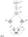
- FIG. 6is a flow diagram illustrating interaction of various PON components to allocate IP addresses.
- FIG. 1is a block diagram illustrating a passive optical network (PON) 10 .
- PON 10may incorporate features that enable IP addresses within a common subnet scope to be assigned to network nodes coupled to different optical fiber links and different interface modules.
- PON 10can be arranged to deliver voice, data and video content (generally “information”) to a number of network nodes via optical fiber links 11 .
- Exemplary components for implementing a PONare commercially available from Optical Solutions, Inc., of Minneapolis, Minn., and designated by the tradename Fiberpath 400TM, including the FiberdriveTM headend bay interface and the FiberpointTM subscriber premise nodes.
- a PON interface 12may receive voice information, for example, from the public switched telephone network (PSTN) 14 via a switch facility 16 .
- PON interface 12may be coupled to one or more Internet service providers (ISP's) on Internet 18 via a router 20 .
- ISP'sInternet service providers
- PON interface 12may receive video content 22 from video content suppliers via a streaming video headend 24 .
- PON interface 12receives the information, and distributes it along optical fiber links 11 A, 11 B (collectively 11 ) to groups 26 A, 26 B (collectively 26 ) of network nodes 28 A, 28 B, 28 C, 28 D (collectively 28 ).
- Each group 26is coupled to a particular optical fiber link 11 .
- Network nodes 28include hardware for receiving information from PON 10 via optical fiber links 11 , and delivering the information to one or more devices within a local area network (LAN) associated with the node.
- LANlocal area network
- each network node 28may serve as a PON access point for one or more computers, network appliances, televisions, wireless devices, or the like.
- PON interface 12may be located near or far from a group 26 of network nodes 28 . In some existing networks, however, PON interface 12 may reside in a central office situated within approximately ten miles from each network node 28 .
- a network node 28may be located at any of a variety of locations, including residential or business sites. In addition, a single network node 28 may operate on a shared basis to deliver information to two or more closely located residences or businesses via copper or additional optical fiber connections, either directly or via a network hub, router or switch.
- a group 26 of network nodes 28may refer to nodes served by PON interface 12 via a common optical fiber link 11 . Each group 26 in FIG. 1 contains two network nodes 28 for purposes of illustration. However, a group 26 may include a single network node, or numerous network nodes 28 .
- Network nodes 28also may include hardware for transmitting information over PON 10 .
- a network node 28may transmit voice information over PSTN 14 via PON interface 12 and switch facility 16 in the course of a telephone conversation.
- a network node 28may transmit data to a variety of network nodes on the Internet via ISP 18 , router 20 and PON interface 12 .
- Multiple network nodes 28typically transmit over a common optical fiber link 11 using time division multiplexing techniques.
- Each network node 28has an IP address that is used to route packets to and from the node.
- the IP addressmay be an IPv4 address or an IPv6 address, although conservation of IP addresses is generally a much greater concern for the 32-bit IPv4 addresses.
- network nodes 28 in different groups 26 served by different optical fiber links 11may be assigned IP addresses within a common subnet scope, thereby conserving IP addresses and promoting increased IP address usage.
- FIG. 2is a block diagram illustrating a PON with groups 26 of network nodes 28 coupled to multiple PON interface modules 34 A, 34 B, 34 C (collectively 34 ) within PON interface 12 .
- PON interface 12may include multiple PON interface modules 34 , e.g., arranged in a common chassis. Each PON interface module 34 may form an independent Ethernet interface that serves a group 26 of nodes 28 coupled to a common optical fiber link 11 . Hence, PON interface module 34 and nodes 28 terminate opposite ends of optical fiber link 11 .
- an optical fiber link 11may include a pair of optical fibers, forming an outgoing link and an incoming link.
- PON interface modules 34receive information from one of more ISPs 18 A, 18 B (collectively 18 ) via network routers 20 A, 20 B (collectively 20 ), and transmit the information to nodes 28 via optical fiber link 11 .
- PON interface modules 34receive information from nodes 28 , and transmit the information to ISPs 18 via routers 20 .
- the transmitted informationmay take the form of data packets.
- FIG. 3is a block diagram illustrating a PON with a DHCP relay agent feature that permits allocation of IP addresses within the same subnet scope to different groups of network nodes.
- each PON interface module 34incorporates a DHCP relay agent 38 A, 38 B (collectively 38 ) that generates DHCP proxy requests for the group 26 of network nodes 28 served by the respective PON interface module 34 .
- a node 28requires an IP address, e.g., upon boot or lease expiration, the node transmits a DHCP request to PON interface module 34 .
- DHCP relay agent 38 within PON interface module 34generates a DHCP proxy request on behalf of node 28 .
- PON interface module 34may maintain a table that maps particular subnets or nodes 28 to particular routers that serve the subnets or nodes. In this manner, DHCP relay agent 38 may associate a DHCP proxy request from a node 28 with an appropriate router 20 and DHCP server 36 . DHCP relay agent 38 may take the form of a software process running on PON interface module 34 .
- Routers 20route the proxy DHCP request to an appropriate ISP 18 based on the subnet to which the node 28 is assigned.
- ISPs 18 A, 18 Btypically may deliver service for one or more different subnets in the PON served by PON interface 12 .
- One of DHCP servers 36 A, 36 B (collectively 36 ) maintained by ISPs 18assigns an IP address to the network node that originated the DHCP request.
- a DHCP server 36 for the appropriate subnetresponds to DHCP relay agent 36 with an IP address within the subnet.
- DHCP relay agent 36sends the IP address to the particular node 28 that generated the DHCP request.
- PON interface module 34makes an entry for the requesting node 28 in its ARP cache, matching the assigned IP address with the media access control (MAC) address of the node.
- MACmedia access control
- a first PON interface module 34 Aacting as a proxy for nodes 28 within a group 26 A, can receive IP addresses with a given subnet scope
- a second PON interface module 34 Bacting as proxy for nodes within a second group 26 B, can receive IP addresses with in the same subnet scope.
- PON interface module 34functions as a gateway within PON 10 , enabling assignment of IP addresses within the same subnet to network nodes 28 coupled to different PON interface modules. This feature avoids allocation of an entire class C subnet to each PON interface module 34 . Instead, different PON interface modules 34 can share a common class C subnet address.
- a single PON interface module 34can serve network nodes 28 with IP addresses within different subnet scopes.
- different ISPs 18can serve network nodes 28 via a common optical fiber link 11 , providing end users, sometimes referred to as “subscribers,” with a choice among two or more ISPs. If an end user elects to take service from a first ISP 18 A, the network node 28 associated with that end user is assigned an IP address within the subnet scope served by the first ISP 18 A. Alternatively, if an end user elects to take service from second ISP 18 B, or other ISPs, the network node 28 is assigned an IP address within a different subnet scope.
- first network node 28 A within a group 26 Acould have an IP address of 192.86.8.x
- a second network node 28 Bcould have an IP address of 192.87.8.x
- first network node 28 Awould be served by a first ISP 18 A (serving Class C subnet 192.86.8.0)
- second network node 28 Bwould be served by a second ISP 18 B (serving Class C subnet 192.87.8.0), both via a common PON interface module 34 A.
- a first network node 28 C within a group 26 B served by another PON interface module 34 Bcould have an IP address of 192.86.8.x, and be served by ISP 18 A.
- a second network node 28 D within the same group 26 B served by PON interface module 34 Bcould have an IP address of 192.87.8.x and be served by ISP 18 B.
- a single DHCP server 36can assign IP addresses to network nodes 28 in first and second groups 26 A, 26 B in response to the DHCP proxy requests generated by first and second DHCP relay agents 38 A, 38 B.
- the subnet scopemay include, e.g., 255 IP addresses.
- the number of network nodes in each of the first and second groups 26 A, 26 Bmay be less than 255, which would result in wasted IP addresses in an existing PON 10 .
- the 255 IP addressescan be distributed over a potentially larger number of network nodes 28 residing in multiple groups 26 .
- the major IP address subnet scopecan be used across the independent PON interface modules 34 , with the use of only one IP address of the major subnet scope used for each PON interface module.
- an ISP 18can consume less class C IP address spaces when attaching to several independent PON interface modules 34 .
- FIG. 4is a block diagram illustrating a PON as shown in FIG. 3 with an ARP agent feature.
- a router 20When an incoming packet bearing one of the assigned IP addresses arrives at a router 20 , i.e., a packet destined for a network node 28 , the router generally will not resolve the correct PON interface module 34 A or 34 B by reference to a single subnet, because either PON interface module may serve nodes within multiple subnets. Rather, router 20 may resolve the address of the destination node 28 by reference to IP addresses of network nodes 28 served by the PON interface module. PON interface module 34 then may resolve the correct network node 28 by reference to an ARP cache maintained by the PON interface module for network nodes to which it has assigned IP addresses.
- a given PON interface module 34may be unable to resolve an appropriate address from the ARP cache.
- the destination node 28 for the packetmay reside within the same subnet as the source node, the destination node may be coupled to a different PON interface module 34 and optical fiber link 11 than the source node.
- the PON interface module 34 that serves the source network node 28will have no record of the IP address of the destination network node in its ARP cache.
- each PON interface module 34may further include an ARP agent 39 A, 39 B (collectively 39 ).
- ARP agent 39may take the form of a software process running on PON interface module 34 .
- PON interface module 34In response to receipt of an ARP request from a network node 28 , PON interface module 34 first consults its local ARP cache for an IP address that matches a MAC address contained in the request. If no entry exists for the particular MAC address, ARP agent 39 generates a proxy ARP request. PON interface module 34 then transmits the proxy ARP request to a router 20 serving the pertinent subnet, i.e., the subnet assigned to the source network node 34 .
- router 20consults its ARP cache 41 A, 41 B (collectively 41 ), and identifies entries for any other PON interface modules 34 that presently serve the same subnet.
- ARP cache 41 A, 41 Bcollectively 41
- the pertinent PON interface moduleconsults its ARP cache and provides the requested address, or returns an ARP failure reply if no such address exists.
- ARP agent 39facilitates transmission of packets among network nodes 28 within a particular subnet, even though the nodes may be distributed across PON 10 in disparate groups 26 coupled to different optical fiber links 11 and different PON interface modules 34 .
- FIG. 5is a block diagram further illustrating the arrangement of a PON as shown in FIG. 3 .
- FIG. 5depicts allocation of IP addresses to network nodes 28 residing in different groups 26 A, 26 B.
- different groups 26 A, 26 B of network nodesare coupled to different PON interface modules 34 A, 34 B, but carry IP addresses that reside in a common subnet 42 .
- multiple endpoints in the PONshare a common subnet.
- the relatively larger number of network nodes 28 in multiple groups 26promotes more efficient use of IP addresses within the PON.
- FIG. 6is a flow diagram illustrating interaction of various PON components to allocate IP addresses in accordance with the invention.
- the PON interface modulepasses the DHCP request to a DHCP relay agent 38 ( 48 ).
- DHCP relay agent 38transmits a DHCP proxy request to DHCP server 36 on behalf of the network node 28 ( 50 ).
- DHCP relay agent 38determines a router 20 and ISP 18 associated with the requesting node, and selects an appropriate link for transmitting the request to the router.
- the PON interface module 34may include a table or other data structure that maintains a mapping between subnets and routers 20 or between nodes and routers.
- the data structuremay be stored on a computer-readable medium such as a hard drive, removable magnetic or optical drive, solid state memory, or the like.
- DHCP relay agent 38may refer to the mapping in selecting an appropriate link to a router.
- DHCP proxy request52
- DHCP server 36retrieves an IP address from a pool of available addresses within the selected subnet scope reserved by the ISP 18 ( 54 ).
- DHCP server 36transmits an IP address lease to PON interface module 34 ( 56 ).
- the IP address leasespecifies an IP address and a duration for which the IP address will remain in force for the requester.
- PON interface moduleUpon receiving the IP address lease ( 58 ), PON interface module passes the IP address lease to DHCP relay agent 38 ( 60 ), which then transmits the IP address lease to the network node 28 that initiated the original DHCP request ( 62 ).
- the network node 28upon receiving the IP address lease ( 64 ) thereafter carries the IP address for the duration of the lease specified by DHCP server 36 .
- network node 28may transmit subnet ARP requests ( 66 ) to resolve the IP addresses of other nodes in the same subnet scope.
- PON interface module 34may incorporate an ARP agent 39 that transmits a proxy ARP request ( 68 ), if necessary, to resolve the address of a destination node.
Landscapes
- Engineering & Computer Science (AREA)
- Computer Networks & Wireless Communication (AREA)
- Signal Processing (AREA)
- Data Exchanges In Wide-Area Networks (AREA)
Abstract
Description
Claims (19)
Priority Applications (5)
| Application Number | Priority Date | Filing Date | Title |
|---|---|---|---|
| US10/144,008US7020157B2 (en) | 2002-05-09 | 2002-05-09 | Network address assignment in a passive optical network |
| EP03724487AEP1502385A4 (en) | 2002-05-09 | 2003-05-06 | Network address assignment in a passive optical network |
| AU2003230283AAU2003230283A1 (en) | 2002-05-09 | 2003-05-06 | Network address assignment in a passive optical network |
| PCT/US2003/014231WO2003096619A1 (en) | 2002-05-09 | 2003-05-06 | Network address assignment in a passive optical network |
| US10/910,523US7525980B2 (en) | 2002-05-09 | 2004-08-03 | Network address assignment in a passive optical network |
Applications Claiming Priority (1)
| Application Number | Priority Date | Filing Date | Title |
|---|---|---|---|
| US10/144,008US7020157B2 (en) | 2002-05-09 | 2002-05-09 | Network address assignment in a passive optical network |
Related Child Applications (1)
| Application Number | Title | Priority Date | Filing Date |
|---|---|---|---|
| US10/910,523ContinuationUS7525980B2 (en) | 2002-05-09 | 2004-08-03 | Network address assignment in a passive optical network |
Publications (2)
| Publication Number | Publication Date |
|---|---|
| US20040213234A1 US20040213234A1 (en) | 2004-10-28 |
| US7020157B2true US7020157B2 (en) | 2006-03-28 |
Family
ID=29418489
Family Applications (2)
| Application Number | Title | Priority Date | Filing Date |
|---|---|---|---|
| US10/144,008Expired - LifetimeUS7020157B2 (en) | 2002-05-09 | 2002-05-09 | Network address assignment in a passive optical network |
| US10/910,523Expired - LifetimeUS7525980B2 (en) | 2002-05-09 | 2004-08-03 | Network address assignment in a passive optical network |
Family Applications After (1)
| Application Number | Title | Priority Date | Filing Date |
|---|---|---|---|
| US10/910,523Expired - LifetimeUS7525980B2 (en) | 2002-05-09 | 2004-08-03 | Network address assignment in a passive optical network |
Country Status (4)
| Country | Link |
|---|---|
| US (2) | US7020157B2 (en) |
| EP (1) | EP1502385A4 (en) |
| AU (1) | AU2003230283A1 (en) |
| WO (1) | WO2003096619A1 (en) |
Cited By (5)
| Publication number | Priority date | Publication date | Assignee | Title |
|---|---|---|---|---|
| US20040042446A1 (en)* | 2002-05-31 | 2004-03-04 | Koch Christopher D. | Maintaining routing information in a passive optical network |
| US20040095943A1 (en)* | 2002-11-15 | 2004-05-20 | Korotin Dmitry O. | Apparatus and method for preserving routable IP addresses using ARP proxy |
| US20050018681A1 (en)* | 2002-05-09 | 2005-01-27 | Optical Solutions, Inc. | Network address assignment in a passive optical network |
| US20060092859A1 (en)* | 2004-10-28 | 2006-05-04 | Samsung Electronics Co., Ltd. | Method, apparatus, and medium for automatically configuring network address |
| US20060140164A1 (en)* | 2004-12-29 | 2006-06-29 | Cisco Technology, Inc. | Methods and apparatus for using DHCP for home address management of nodes attached to an edge device and for performing mobility and address management as a proxy home agent |
Families Citing this family (16)
| Publication number | Priority date | Publication date | Assignee | Title |
|---|---|---|---|---|
| US20030223749A1 (en)* | 2002-05-31 | 2003-12-04 | David Funk | Optical network management |
| US20050185635A1 (en)* | 2003-07-30 | 2005-08-25 | C.L. Nagendra | Virtual service provider system and method for delivering media services to an end user |
| US7457255B2 (en)* | 2004-06-25 | 2008-11-25 | Apple Inc. | Method and apparatus for providing link-local IPv4 addressing across multiple interfaces of a network node |
| CN100493102C (en)* | 2005-12-01 | 2009-05-27 | 中国科学院计算技术研究所 | A Method for Allocating IP Addresses in Broadband Wireless Metropolitan Area Network |
| US7586912B2 (en)* | 2006-07-28 | 2009-09-08 | Cisco Technology, Inc. | Techniques for exchanging DHCP information among DHCP relay agents and DHCP servers |
| US7836206B2 (en)* | 2006-10-02 | 2010-11-16 | Futurewei Technologies, Inc. | Context transfer and common IP address for DHCP proxy solution in WiMAX |
| US7821941B2 (en)* | 2006-11-03 | 2010-10-26 | Cisco Technology, Inc. | Automatically controlling operation of a BRAS device based on encapsulation information |
| US7804848B2 (en)* | 2007-02-28 | 2010-09-28 | Cisco Technology, Inc. | Setting a forwarding address in an internet protocol version 6 (IPv6) routing protocol domain at a boundary with a different routing protocol domain |
| US8572217B2 (en)* | 2008-02-15 | 2013-10-29 | Ericsson Ab | Methods and apparatuses for dynamically provisioning a dynamic host configuration protocol (DHCP) client as a clientless internet protocol services (CLIPS) subscriber on a last-resort interface |
| US9106714B2 (en)* | 2009-07-23 | 2015-08-11 | Cisco Technology, Inc. | Plug and play provisioning of voice over IP network devices |
| EP2795811B1 (en)* | 2011-12-22 | 2018-08-22 | CommScope Technologies LLC | Fiber optic wall plate with redundancy system |
| US9282061B1 (en)* | 2012-04-13 | 2016-03-08 | Adtran, Inc. | Systems and methods for handling ARP messages in modular network devices |
| KR102013816B1 (en) | 2013-10-29 | 2019-08-23 | 삼성전자주식회사 | Method and apparatus for base station self-configuration in distributed network architecture |
| US9712489B2 (en)* | 2014-07-29 | 2017-07-18 | Aruba Networks, Inc. | Client device address assignment following authentication |
| US10678745B2 (en)* | 2017-05-08 | 2020-06-09 | Keysight Technologies Singapore (Sales) Pte. Ltd. | Providing computing device configuration information via a light transmission |
| US12341749B2 (en)* | 2022-11-09 | 2025-06-24 | Charter Communications Operating, Llc | Proxy address resolution protocol for distributed local area network communications |
Citations (17)
| Publication number | Priority date | Publication date | Assignee | Title |
|---|---|---|---|---|
| WO1997048210A1 (en) | 1996-06-14 | 1997-12-18 | Bell Communications Research, Inc. | Logical ip address assignment in atm lan |
| EP0946027A2 (en) | 1998-03-26 | 1999-09-29 | Hewlett-Packard Company | A method and apparatus for configuring a network node to be its own gateway |
| US6091737A (en) | 1996-11-15 | 2000-07-18 | Multi-Tech Systems, Inc. | Remote communications server system |
| WO2000044132A2 (en) | 1999-01-25 | 2000-07-27 | Telefonaktiebolaget Lm Ericsson (Publ) | Secure and efficient address resolution for client stations connected over wide area network links to ip networks such as the internet |
| US6101182A (en)* | 1996-04-18 | 2000-08-08 | Bell Atlantic Network Services, Inc. | Universal access multimedia data network |
| US6178455B1 (en) | 1997-01-17 | 2001-01-23 | Scientific-Atlanta, Inc. | Router which dynamically requests a set of logical network addresses and assigns addresses in the set to hosts connected to the router |
| US6212563B1 (en) | 1998-10-01 | 2001-04-03 | 3Com Corporation | Method and system for setting and managing externally provided internet protocol addresses using the dynamic host configuration protocol |
| US6282201B1 (en) | 1997-11-20 | 2001-08-28 | Cisco Technology, Inc. | Method for configuring distributed internet protocol gateways with LAN emulation |
| US6289377B1 (en)* | 1997-11-10 | 2001-09-11 | General Instrument Corporation | Dynamic network configuration of a one-way adapter using a proxy agent that communicates with a resource server through a configured return path adapter |
| US20010030977A1 (en)* | 1999-12-30 | 2001-10-18 | May Lauren T. | Proxy methods for IP address assignment and universal access mechanism |
| US20020023273A1 (en)* | 2000-08-14 | 2002-02-21 | Hanmi Pharm. Co., Ltd. | Apparatus for providing a multiple internet connection service using a hybrid fiber coaxial cable network |
| EP1202494A2 (en) | 2000-10-31 | 2002-05-02 | Marconi Communications, Inc. | Method and system for remotely maintaining and provisioning equipment over a wide area network |
| US6424654B1 (en)* | 1997-11-21 | 2002-07-23 | Komatsu Ltd. | Network system and DHCP server selection method |
| US20030069954A1 (en)* | 2001-10-05 | 2003-04-10 | Adc Telecommunications, Inc. | Subnet pooling |
| US20030088700A1 (en)* | 2001-11-02 | 2003-05-08 | Microsoft Corporation | Method and system for facilitating communication between nodes on different segments of a network |
| US6574664B1 (en)* | 1999-01-29 | 2003-06-03 | Hewlett-Packard Development Company, L.P. | Apparatus and method for IP and MAC address discovery at the process layer |
| US6578074B1 (en)* | 1999-06-25 | 2003-06-10 | Mediaone Group, Inc. | Provisioning server enhancement |
Family Cites Families (14)
| Publication number | Priority date | Publication date | Assignee | Title |
|---|---|---|---|---|
| US6334219B1 (en) | 1994-09-26 | 2001-12-25 | Adc Telecommunications Inc. | Channel selection for a hybrid fiber coax network |
| JP3494562B2 (en) | 1997-10-15 | 2004-02-09 | 株式会社東芝 | Network management system |
| US6229788B1 (en) | 1998-05-27 | 2001-05-08 | Nortel Networks Limited | Method and apparatus for traffic shaping in a broadband fiber-based access system |
| US6510162B1 (en)* | 1998-05-27 | 2003-01-21 | 3Com Corporation | System and method for managing channel usage in a data over cable system |
| US6697360B1 (en)* | 1998-09-02 | 2004-02-24 | Cisco Technology, Inc. | Method and apparatus for auto-configuring layer three intermediate computer network devices |
| US6640251B1 (en)* | 1999-03-12 | 2003-10-28 | Nortel Networks Limited | Multicast-enabled address resolution protocol (ME-ARP) |
| US7058007B1 (en)* | 2000-01-18 | 2006-06-06 | Cisco Technology, Inc. | Method for a cable modem to rapidly switch to a backup CMTS |
| US6616606B1 (en)* | 2000-05-19 | 2003-09-09 | Welch Allyn Protocol, Inc. | Patient monitoring system |
| US6907470B2 (en)* | 2000-06-29 | 2005-06-14 | Hitachi, Ltd. | Communication apparatus for routing or discarding a packet sent from a user terminal |
| US7272137B2 (en) | 2001-05-14 | 2007-09-18 | Nortel Networks Limited | Data stream filtering apparatus and method |
| US7051089B1 (en)* | 2001-10-24 | 2006-05-23 | Cisco Technology, Inc. | Techniques for automatically delegating address spaces among dynamic host configuration servers |
| US7072337B1 (en) | 2002-01-25 | 2006-07-04 | 3Com Corporation | System and method for resolving network addresses for network devices on distributed network subnets |
| US7181142B1 (en) | 2002-04-09 | 2007-02-20 | Time Warner Cable Inc. | Broadband optical network apparatus and method |
| US7020157B2 (en) | 2002-05-09 | 2006-03-28 | Optical Solutions, Inc. | Network address assignment in a passive optical network |
- 2002
- 2002-05-09USUS10/144,008patent/US7020157B2/ennot_activeExpired - Lifetime
- 2003
- 2003-05-06EPEP03724487Apatent/EP1502385A4/ennot_activeWithdrawn
- 2003-05-06AUAU2003230283Apatent/AU2003230283A1/ennot_activeAbandoned
- 2003-05-06WOPCT/US2003/014231patent/WO2003096619A1/ennot_activeApplication Discontinuation
- 2004
- 2004-08-03USUS10/910,523patent/US7525980B2/ennot_activeExpired - Lifetime
Patent Citations (18)
| Publication number | Priority date | Publication date | Assignee | Title |
|---|---|---|---|---|
| US6101182A (en)* | 1996-04-18 | 2000-08-08 | Bell Atlantic Network Services, Inc. | Universal access multimedia data network |
| WO1997048210A1 (en) | 1996-06-14 | 1997-12-18 | Bell Communications Research, Inc. | Logical ip address assignment in atm lan |
| US6091737A (en) | 1996-11-15 | 2000-07-18 | Multi-Tech Systems, Inc. | Remote communications server system |
| US6178455B1 (en) | 1997-01-17 | 2001-01-23 | Scientific-Atlanta, Inc. | Router which dynamically requests a set of logical network addresses and assigns addresses in the set to hosts connected to the router |
| US6301223B1 (en) | 1997-01-17 | 2001-10-09 | Scientific-Atlanta, Inc. | Method of using routing protocols to reroute packets during a link failure |
| US6289377B1 (en)* | 1997-11-10 | 2001-09-11 | General Instrument Corporation | Dynamic network configuration of a one-way adapter using a proxy agent that communicates with a resource server through a configured return path adapter |
| US6282201B1 (en) | 1997-11-20 | 2001-08-28 | Cisco Technology, Inc. | Method for configuring distributed internet protocol gateways with LAN emulation |
| US6424654B1 (en)* | 1997-11-21 | 2002-07-23 | Komatsu Ltd. | Network system and DHCP server selection method |
| EP0946027A2 (en) | 1998-03-26 | 1999-09-29 | Hewlett-Packard Company | A method and apparatus for configuring a network node to be its own gateway |
| US6212563B1 (en) | 1998-10-01 | 2001-04-03 | 3Com Corporation | Method and system for setting and managing externally provided internet protocol addresses using the dynamic host configuration protocol |
| WO2000044132A2 (en) | 1999-01-25 | 2000-07-27 | Telefonaktiebolaget Lm Ericsson (Publ) | Secure and efficient address resolution for client stations connected over wide area network links to ip networks such as the internet |
| US6574664B1 (en)* | 1999-01-29 | 2003-06-03 | Hewlett-Packard Development Company, L.P. | Apparatus and method for IP and MAC address discovery at the process layer |
| US6578074B1 (en)* | 1999-06-25 | 2003-06-10 | Mediaone Group, Inc. | Provisioning server enhancement |
| US20010030977A1 (en)* | 1999-12-30 | 2001-10-18 | May Lauren T. | Proxy methods for IP address assignment and universal access mechanism |
| US20020023273A1 (en)* | 2000-08-14 | 2002-02-21 | Hanmi Pharm. Co., Ltd. | Apparatus for providing a multiple internet connection service using a hybrid fiber coaxial cable network |
| EP1202494A2 (en) | 2000-10-31 | 2002-05-02 | Marconi Communications, Inc. | Method and system for remotely maintaining and provisioning equipment over a wide area network |
| US20030069954A1 (en)* | 2001-10-05 | 2003-04-10 | Adc Telecommunications, Inc. | Subnet pooling |
| US20030088700A1 (en)* | 2001-11-02 | 2003-05-08 | Microsoft Corporation | Method and system for facilitating communication between nodes on different segments of a network |
Non-Patent Citations (10)
| Title |
|---|
| "A Practical Approach to Assigning Subnet Masks" John P. Abraham, Proceedings of the ETCE/OMAE 2000 Joint Conference, New Orleans, LA 2000. |
| "AT&T Broadband ISP Choice Trial A Success" AT&T News Release, Jun. 7, 2001. |
| "Dynamic Host Configuration Protocol" R. Droms, Bucknell University, RFC 2131, Mar. 1997. |
| "How Do I Set Up a DHCP Relay Agent and Scope for a LAN Segment That Does Not have A DHCP Server" www.ezine.com/QandA/DHCPRelay.html, Apr. 15, 2002. |
| "Introduction to Internet Networking" http://supportnet.merit.edu/. |
| "Understanding IP Addressing: Everything You Ever Wanted to Know" Chuck Semeria, NSD Marketing, 3Com Corporation, Apr. 26, 1996. |
| Copy of Supplemental European Search Report for patent application number 03 724 487.8-2416, filed Nov. 2, 2004, 6 pages (Sep. 14, 2005). |
| Copy of Supplemental Partial European Search Report for patent application No. 03 724 487.8-2416, filed Nov. 2, 2004, 5 pages, (Jun. 17, 2005). |
| Kim Kinnear et al., "Subnet Selection sub-option for Relay Agent Information Option", Internet Engineering Task Force, IETF, Mar. 2001, (7 pages). |
| Tom Sheldon, "FTTH (Fiber to the Home)" LINKTIONARY, Online, Mar. 22, 2002. http://www.linktionary.com/f/fiber<SUB>-</SUB>home.html. |
Cited By (8)
| Publication number | Priority date | Publication date | Assignee | Title |
|---|---|---|---|---|
| US20050018681A1 (en)* | 2002-05-09 | 2005-01-27 | Optical Solutions, Inc. | Network address assignment in a passive optical network |
| US7525980B2 (en) | 2002-05-09 | 2009-04-28 | Calix Networks, Inc. | Network address assignment in a passive optical network |
| US20040042446A1 (en)* | 2002-05-31 | 2004-03-04 | Koch Christopher D. | Maintaining routing information in a passive optical network |
| US20040095943A1 (en)* | 2002-11-15 | 2004-05-20 | Korotin Dmitry O. | Apparatus and method for preserving routable IP addresses using ARP proxy |
| US7512136B2 (en)* | 2002-11-15 | 2009-03-31 | The Directv Group, Inc. | Apparatus and method for preserving routable IP addresses using ARP proxy |
| US20060092859A1 (en)* | 2004-10-28 | 2006-05-04 | Samsung Electronics Co., Ltd. | Method, apparatus, and medium for automatically configuring network address |
| US20060140164A1 (en)* | 2004-12-29 | 2006-06-29 | Cisco Technology, Inc. | Methods and apparatus for using DHCP for home address management of nodes attached to an edge device and for performing mobility and address management as a proxy home agent |
| US8059661B2 (en)* | 2004-12-29 | 2011-11-15 | Cisco Technology, Inc. | Methods and apparatus for using DHCP for home address management of nodes attached to an edge device and for performing mobility and address management as a proxy home agent |
Also Published As
| Publication number | Publication date |
|---|---|
| EP1502385A1 (en) | 2005-02-02 |
| EP1502385A4 (en) | 2005-11-02 |
| US20040213234A1 (en) | 2004-10-28 |
| AU2003230283A1 (en) | 2003-11-11 |
| WO2003096619A1 (en) | 2003-11-20 |
| US7525980B2 (en) | 2009-04-28 |
| US20050018681A1 (en) | 2005-01-27 |
Similar Documents
| Publication | Publication Date | Title |
|---|---|---|
| US7020157B2 (en) | Network address assignment in a passive optical network | |
| EP1125421B1 (en) | Dns relay module in a digital network modem | |
| US7010585B2 (en) | DNS server, DHCP server, terminal and communication system | |
| US7046666B1 (en) | Method and apparatus for communicating between divergent networks using media access control communications | |
| US9407495B2 (en) | Combining locally addressed devices and wide area network (WAN) addressed devices on a single network | |
| US20040111529A1 (en) | Dynamic host based load balancing of a multihomed network | |
| US20030051052A1 (en) | Addressing scheme for wireless mobile clients | |
| JP2004129126A (en) | Address assignment system | |
| KR100584342B1 (en) | IP address allocation method in Ethernet passive optical subscriber network | |
| WO1997048210A1 (en) | Logical ip address assignment in atm lan | |
| US9319235B2 (en) | Authentication, authorization, and accounting based on an automatically generated username | |
| US20130089092A1 (en) | Method for preventing address conflict, and access node | |
| CA2440350A1 (en) | Access networks | |
| US7570647B2 (en) | LAN type internet access network and subscriber line accommodation method for use in the same network | |
| US20040042446A1 (en) | Maintaining routing information in a passive optical network | |
| US20090141705A1 (en) | Device and method for address-mapping | |
| EP1955478B1 (en) | Method ahd arrangement in an access system | |
| JP2000341337A (en) | Inter-private-network connection system and its method by ip masquerade | |
| KR20050002345A (en) | Leyer 3 switch having interceptive function of using fixed internet protocol address and method therefor |
Legal Events
| Date | Code | Title | Description |
|---|---|---|---|
| AS | Assignment | Owner name:OPTICAL SOLUTIONS, INC., MINNESOTA Free format text:ASSIGNMENT OF ASSIGNORS INTEREST;ASSIGNORS:KOCH, CHRISTOPHER D.;JOHNSON, MILTON J.;REEL/FRAME:012898/0324 Effective date:20020509 | |
| AS | Assignment | Owner name:SILICON VALLEY BANK, CALIFORNIA Free format text:SECURITY INTEREST;ASSIGNOR:OPTICAL SOLUTIONS, INC.;REEL/FRAME:016059/0161 Effective date:20040816 | |
| AS | Assignment | Owner name:PARTNERS FOR GROWTH, L.P.,CALIFORNIA Free format text:SECURITY AGREEMENT;ASSIGNOR:OPTICAL SOLUTIONS, INC.;REEL/FRAME:016345/0458 Effective date:20050802 Owner name:PARTNERS FOR GROWTH, L.P., CALIFORNIA Free format text:SECURITY AGREEMENT;ASSIGNOR:OPTICAL SOLUTIONS, INC.;REEL/FRAME:016345/0458 Effective date:20050802 | |
| AS | Assignment | Owner name:OPTICAL SOLUTIONS, INC.,MINNESOTA Free format text:TERMINATION OF SECURITY INTEREST;ASSIGNOR:PARTNERS FOR GROWTH, L.P.;REEL/FRAME:017145/0865 Effective date:20060209 Owner name:OPTICAL SOLUTIONS, INC., MINNESOTA Free format text:TERMINATION OF SECURITY INTEREST;ASSIGNOR:PARTNERS FOR GROWTH, L.P.;REEL/FRAME:017145/0865 Effective date:20060209 | |
| STCF | Information on status: patent grant | Free format text:PATENTED CASE | |
| AS | Assignment | Owner name:OPTICAL SOLUTIONS, INC., MASSACHUSETTS Free format text:RELEASE BY SECURED PARTY;ASSIGNOR:SILICON VALLEY BANK;REEL/FRAME:017783/0365 Effective date:20060404 | |
| CC | Certificate of correction | ||
| AS | Assignment | Owner name:CALIX NETWORKS, INC.,CALIFORNIA Free format text:MERGER;ASSIGNOR:OPTICAL SOLUTIONS, INC.;REEL/FRAME:019009/0826 Effective date:20061231 Owner name:CALIX NETWORKS, INC., CALIFORNIA Free format text:MERGER;ASSIGNOR:OPTICAL SOLUTIONS, INC.;REEL/FRAME:019009/0826 Effective date:20061231 | |
| AS | Assignment | Owner name:WHITE OAK GLOBAL ADVISORS, LLC, CALIFORNIA Free format text:ASSIGNMENT OF ASSIGNORS INTEREST;ASSIGNOR:CALIX NETWORKS, INC.;REEL/FRAME:021371/0500 Effective date:20080701 Owner name:WHITE OAK GLOBAL ADVISORS, LLC,CALIFORNIA Free format text:ASSIGNMENT OF ASSIGNORS INTEREST;ASSIGNOR:CALIX NETWORKS, INC.;REEL/FRAME:021371/0500 Effective date:20080701 | |
| AS | Assignment | Owner name:SILICON VALLEY BANK, CALIFORNIA Free format text:SECURITY AGREEMENT;ASSIGNOR:CALIX NETWORKS, INC.;REEL/FRAME:021462/0012 Effective date:20080829 Owner name:SILICON VALLEY BANK,CALIFORNIA Free format text:SECURITY AGREEMENT;ASSIGNOR:CALIX NETWORKS, INC.;REEL/FRAME:021462/0012 Effective date:20080829 | |
| FPAY | Fee payment | Year of fee payment:4 | |
| AS | Assignment | Owner name:CALIX NETWORKS, INC., CALIFORNIA Free format text:RELEASE BY SECURED PARTY;ASSIGNOR:WHITE OAK GLOBAL ADVISORS, LLC;REEL/FRAME:023471/0944 Effective date:20091105 Owner name:CALIX NETWORKS, INC.,CALIFORNIA Free format text:RELEASE BY SECURED PARTY;ASSIGNOR:WHITE OAK GLOBAL ADVISORS, LLC;REEL/FRAME:023471/0944 Effective date:20091105 | |
| AS | Assignment | Owner name:CALIX, INC.,CALIFORNIA Free format text:CHANGE OF NAME;ASSIGNOR:CALIX NETWORKS, INC.;REEL/FRAME:024492/0841 Effective date:20100322 Owner name:CALIX, INC., CALIFORNIA Free format text:CHANGE OF NAME;ASSIGNOR:CALIX NETWORKS, INC.;REEL/FRAME:024492/0841 Effective date:20100322 | |
| AS | Assignment | Owner name:BANK OF AMERICA, N.A., AS ADMINISTRATIVE AGENT, CA Free format text:SECURITY AGREEMENT;ASSIGNOR:CALIX, INC.;REEL/FRAME:030899/0597 Effective date:20130729 | |
| AS | Assignment | Owner name:CALIX NETWORKS, INC., CALIFORNIA Free format text:RELEASE BY SECURED PARTY;ASSIGNOR:SILICON VALLEY BANK;REEL/FRAME:030906/0224 Effective date:20130729 | |
| FPAY | Fee payment | Year of fee payment:8 | |
| AS | Assignment | Owner name:CALIX, INC., CALIFORNIA Free format text:RELEASE BY SECURED PARTY;ASSIGNOR:BANK OF AMERICA, N.A., AS ADMINISTRATIVE AGENT FOR LENDERS;REEL/FRAME:043494/0549 Effective date:20170807 Owner name:SILICON VALLEY BANK, CALIFORNIA Free format text:SECURITY INTEREST;ASSIGNOR:CALIX, INC.;REEL/FRAME:043495/0424 Effective date:20170807 | |
| MAFP | Maintenance fee payment | Free format text:PAYMENT OF MAINTENANCE FEE, 12TH YEAR, LARGE ENTITY (ORIGINAL EVENT CODE: M1553) Year of fee payment:12 | |
| AS | Assignment | Owner name:CALIX, INC., CALIFORNIA Free format text:RELEASE OF SECURITY INTEREST IN INTELLECTUAL PROPERTY;ASSIGNOR:SILICON VALLEY BANK;REEL/FRAME:051714/0883 Effective date:20200127 | |
| AS | Assignment | Owner name:BANK OF AMERICA, N.A., AS AGENT, OREGON Free format text:SECURITY INTEREST;ASSIGNOR:CALIX, INC.;REEL/FRAME:051719/0348 Effective date:20200127 | |
| AS | Assignment | Owner name:CALIX, INC., CALIFORNIA Free format text:RELEASE BY SECURED PARTY;ASSIGNOR:BANK OF AMERICA, N.A.;REEL/FRAME:059802/0579 Effective date:20220301 | |
| AS | Assignment | Owner name:CALIX, INC., CALIFORNIA Free format text:RELEASE BY SECURED PARTY;ASSIGNOR:BANK OF AMERICA, N.A.;REEL/FRAME:059929/0453 Effective date:20220502 |