US7020130B2 - Method and apparatus for providing integrated voice and data services over a common interface device - Google Patents
Method and apparatus for providing integrated voice and data services over a common interface deviceDownload PDFInfo
- Publication number
- US7020130B2 US7020130B2US10/800,394US80039404AUS7020130B2US 7020130 B2US7020130 B2US 7020130B2US 80039404 AUS80039404 AUS 80039404AUS 7020130 B2US7020130 B2US 7020130B2
- Authority
- US
- United States
- Prior art keywords
- signaling
- network
- calling party
- call
- sip
- Prior art date
- Legal status (The legal status is an assumption and is not a legal conclusion. Google has not performed a legal analysis and makes no representation as to the accuracy of the status listed.)
- Expired - Lifetime
Links
Images


Classifications
- H—ELECTRICITY
- H04—ELECTRIC COMMUNICATION TECHNIQUE
- H04L—TRANSMISSION OF DIGITAL INFORMATION, e.g. TELEGRAPHIC COMMUNICATION
- H04L65/00—Network arrangements, protocols or services for supporting real-time applications in data packet communication
- H04L65/80—Responding to QoS
- H—ELECTRICITY
- H04—ELECTRIC COMMUNICATION TECHNIQUE
- H04L—TRANSMISSION OF DIGITAL INFORMATION, e.g. TELEGRAPHIC COMMUNICATION
- H04L12/00—Data switching networks
- H04L12/64—Hybrid switching systems
- H04L12/6418—Hybrid transport
- H—ELECTRICITY
- H04—ELECTRIC COMMUNICATION TECHNIQUE
- H04L—TRANSMISSION OF DIGITAL INFORMATION, e.g. TELEGRAPHIC COMMUNICATION
- H04L41/00—Arrangements for maintenance, administration or management of data switching networks, e.g. of packet switching networks
- H04L41/50—Network service management, e.g. ensuring proper service fulfilment according to agreements
- H04L41/508—Network service management, e.g. ensuring proper service fulfilment according to agreements based on type of value added network service under agreement
- H04L41/5087—Network service management, e.g. ensuring proper service fulfilment according to agreements based on type of value added network service under agreement wherein the managed service relates to voice services
- H—ELECTRICITY
- H04—ELECTRIC COMMUNICATION TECHNIQUE
- H04L—TRANSMISSION OF DIGITAL INFORMATION, e.g. TELEGRAPHIC COMMUNICATION
- H04L65/00—Network arrangements, protocols or services for supporting real-time applications in data packet communication
- H04L65/10—Architectures or entities
- H04L65/102—Gateways
- H04L65/1043—Gateway controllers, e.g. media gateway control protocol [MGCP] controllers
- H—ELECTRICITY
- H04—ELECTRIC COMMUNICATION TECHNIQUE
- H04L—TRANSMISSION OF DIGITAL INFORMATION, e.g. TELEGRAPHIC COMMUNICATION
- H04L65/00—Network arrangements, protocols or services for supporting real-time applications in data packet communication
- H04L65/1066—Session management
- H04L65/1101—Session protocols
- H04L65/1104—Session initiation protocol [SIP]
- H—ELECTRICITY
- H04—ELECTRIC COMMUNICATION TECHNIQUE
- H04M—TELEPHONIC COMMUNICATION
- H04M7/00—Arrangements for interconnection between switching centres
- H04M7/0024—Services and arrangements where telephone services are combined with data services
- H04M7/0057—Services where the data services network provides a telephone service in addition or as an alternative, e.g. for backup purposes, to the telephone service provided by the telephone services network
- H—ELECTRICITY
- H04—ELECTRIC COMMUNICATION TECHNIQUE
- H04M—TELEPHONIC COMMUNICATION
- H04M7/00—Arrangements for interconnection between switching centres
- H04M7/006—Networks other than PSTN/ISDN providing telephone service, e.g. Voice over Internet Protocol (VoIP), including next generation networks with a packet-switched transport layer
- H04M7/0066—Details of access arrangements to the networks
- H04M7/0069—Details of access arrangements to the networks comprising a residential gateway, e.g. those which provide an adapter for POTS or ISDN terminals
- H—ELECTRICITY
- H04—ELECTRIC COMMUNICATION TECHNIQUE
- H04L—TRANSMISSION OF DIGITAL INFORMATION, e.g. TELEGRAPHIC COMMUNICATION
- H04L12/00—Data switching networks
- H04L12/64—Hybrid switching systems
- H04L12/6418—Hybrid transport
- H04L2012/6445—Admission control
- H—ELECTRICITY
- H04—ELECTRIC COMMUNICATION TECHNIQUE
- H04L—TRANSMISSION OF DIGITAL INFORMATION, e.g. TELEGRAPHIC COMMUNICATION
- H04L12/00—Data switching networks
- H04L12/64—Hybrid switching systems
- H04L12/6418—Hybrid transport
- H04L2012/6486—Signalling Protocols
- H—ELECTRICITY
- H04—ELECTRIC COMMUNICATION TECHNIQUE
- H04L—TRANSMISSION OF DIGITAL INFORMATION, e.g. TELEGRAPHIC COMMUNICATION
- H04L41/00—Arrangements for maintenance, administration or management of data switching networks, e.g. of packet switching networks
- H04L41/02—Standardisation; Integration
- H04L41/0213—Standardised network management protocols, e.g. simple network management protocol [SNMP]
- H—ELECTRICITY
- H04—ELECTRIC COMMUNICATION TECHNIQUE
- H04L—TRANSMISSION OF DIGITAL INFORMATION, e.g. TELEGRAPHIC COMMUNICATION
- H04L41/00—Arrangements for maintenance, administration or management of data switching networks, e.g. of packet switching networks
- H04L41/06—Management of faults, events, alarms or notifications
- H—ELECTRICITY
- H04—ELECTRIC COMMUNICATION TECHNIQUE
- H04L—TRANSMISSION OF DIGITAL INFORMATION, e.g. TELEGRAPHIC COMMUNICATION
- H04L41/00—Arrangements for maintenance, administration or management of data switching networks, e.g. of packet switching networks
- H04L41/50—Network service management, e.g. ensuring proper service fulfilment according to agreements
- H04L41/5003—Managing SLA; Interaction between SLA and QoS
- H—ELECTRICITY
- H04—ELECTRIC COMMUNICATION TECHNIQUE
- H04L—TRANSMISSION OF DIGITAL INFORMATION, e.g. TELEGRAPHIC COMMUNICATION
- H04L61/00—Network arrangements, protocols or services for addressing or naming
- H—ELECTRICITY
- H04—ELECTRIC COMMUNICATION TECHNIQUE
- H04L—TRANSMISSION OF DIGITAL INFORMATION, e.g. TELEGRAPHIC COMMUNICATION
- H04L69/00—Network arrangements, protocols or services independent of the application payload and not provided for in the other groups of this subclass
- H04L69/08—Protocols for interworking; Protocol conversion
Definitions
- the present inventionrelates to communications, and more particularly, to supporting communication services over an integrated interface device.
- IPInternet Protocol
- IP telephonywhich is also referred to as Voice-over-IP (VoIP)
- VoIPVoice-over-IP
- VoIPVoice-over-IP
- VoIPVoice-over-IP
- Usersalso have turned to IP telephony as a matter of convenience in that both voice and data services are accessible through a single piece of equipment, namely a personal computer.
- traditional analog phonescan enjoy the benefits of VoIP technology through the use of network adapters.
- the continual integration of voice and data servicesfurther drives this demand for IP telephony applications. Such integration stems, in part, from the emergence of ubiquitous broadband services.
- SIPSession Initiation Protocol
- CPECustomer Premise Equipment
- QoSquality of service
- Ethernetdata network
- the deviceconverts SIP signaling to non-SIP compliant signaling (e.g., PRI and Channel Associated Signaling (CAS)) in support of calls.
- SIPSession Initiation Protocol
- CPECustomer Premise Equipment
- CASChannel Associated Signaling
- an apparatus for supporting a plurality of data and voice servicesincludes a network interface configured to receive a call from a calling party device to a called party device. Also, the apparatus includes signaling conversion logic configured to convert between Session Initiation Protocol (SIP) signaling and circuit-switched telephony signaling to support the call, wherein addressing information of the calling party device is preserved in the conversion, and the called party device includes one of a telephone station and a SIP client.
- the apparatusfurther includes a voice port coupled to the signaling conversion logic and configured to communicate selectively with the telephone station; and a data port configured to communicate selectively with the SIP client.
- SIPSession Initiation Protocol
- a method for supporting a plurality of data and voice services over a common customer premise equipment (CPE) deviceincludes receiving a call from a calling party device to a called party device.
- the methodalso includes converting between Session Initiation Protocol (SIP) signaling and circuit-switched telephony signaling to support the call, wherein addressing information of the calling party device is preserved in the conversion, and the called party device includes one of a telephone station and a SIP client.
- the methodincludes selectively communicating via a voice port interfacing the telephone station; and selectively communicating via a data port interfacing the SIP client.
- SIPSession Initiation Protocol
- a computer-readable mediumcarrying one or more sequences of one or more instructions for supporting a plurality of data and voice services over a common customer premise equipment (CPE) device.
- the one or more sequences of one or more instructionsincluding instructions which, when executed by one or more processors, cause the one or more processors to perform the steps of receiving a call from a calling party device to a called party device; converting between Session Initiation Protocol (SIP) signaling and circuit-switched telephony signaling to support the call, wherein addressing information of the calling party device is preserved in the conversion, and the called party device includes one of a telephone station and a SIP client.
- Other stepsinclude selectively communicating via a voice port interfacing the telephone station; and selectively communicating via a data port interfacing the SIP client.
- a method for providing multiple communication services over a common interface deviceincludes receiving telephony signaling pertaining to a call from a calling party according to a first signaling protocol compatible with a circuit-switched network. The method also includes generating a call setup message according to a second signaling protocol compatible with a data network; and determining whether the telephony signaling comprises address information pertaining to the calling party. Further, the method includes inserting a header into the call setup message. The header contains a network address corresponding to the address information.
- a network devicefor providing multiple communication services.
- the deviceincludes means for receiving telephony signaling pertaining to a call from a calling party according to a first signaling protocol compatible with a circuit-switched network; means for generating a call setup message according to a second signaling protocol compatible with a data network; means for determining whether the telephony signaling comprises address information pertaining to the calling party; and means for inserting a header into the call setup message.
- the headercontains a network address corresponding to the address information.
- a method for managing signaling in a communications systemincludes receiving a first signaling message compliant with a Session Initiation Protocol (SIP) and indicative of a call to a telephony system that uses a telephony signaling protocol that is not compliant with SIP.
- the methodalso includes creating a second signaling message according to the telephony signaling protocol.
- the methodincludes responsive to whether the first signaling message includes a remote party identification header, providing a calling party number element in the second signaling message, wherein the content of the calling party number element is derived from the content of the remote party identification header.
- a network devicefor supporting integrated voice and data services.
- the network deviceincludes one or more voice ports configured to communicate with one or more analog devices; one or more data ports configured to communicate with one or more Session Initiation Protocol (SIP) devices; one or more network ports configured to communicate with a network; and firewall logic configured to filter traffic received from the one or more network ports.
- the network devicealso includes quality of service (QoS) logic configured to perform QoS processing on traffic received from the one or more voice ports, the one or more data ports, and the one or more network ports.
- QoSquality of service
- a network devicefor supporting integrated voice and data services.
- the network deviceincludes at least one voice port configured to communicate with at least one analog telephone; at least one voice trunk configured to communicate with a private branch exchange; at least one data port configured to communicate with at least one Session Initiation Protocol (SIP) device; and at least one network port configured to communicate with a network.
- the network deviceincludes management logic configured to provide quality of service (QoS) management and security for the at least one voice port, the at least one voice trunk, the at least one data port, and the at least one network port.
- QoSquality of service
- FIG. 1is a diagram of a communication system utilizing an interface device at a customer premise to support integrated voice and data services, according to an embodiment of the present invention
- FIG. 2is a diagram of the interface device used in the system of FIG. 1 ;
- FIG. 3is a diagram of the management logic employed in the interface device of FIG. 2 ;
- FIG. 4is a diagram showing a topology hiding operation of the network address translation (NAT)/port address translation (PAT) logic of FIG. 3 ;
- FIG. 5is a diagram of the voice port logic of FIG. 2 ;
- FIG. 6is a flowchart of a process for routing traffic from a network through the interface device of FIG. 2 ;
- FIG. 7is a flowchart of a process for routing traffic from one or more customer devices through the interface device of FIG. 2 ;
- FIGS. 8 a and 8 bare a flowchart of a process for converting Time Division Multiplexing (TDM) signaling to Session Initiation Protocol (SIP) signaling to support call processing, according to an embodiment of the present invention
- FIGS. 9 a and 9 bare a flowchart of a process for converting Session Initiation Protocol (SIP) signaling to Time Division Multiplexing (TDM) signaling to support call processing, according to an embodiment of the present invention.
- SIPSession Initiation Protocol
- TDMTime Division Multiplexing
- FIG. 10is a diagram of a computer system that can be used to implement an embodiment of the present invention.
- CPECustomer Premise Equipment
- FIG. 1is a diagram of a communication system utilizing an interface device at a customer premise to support integrated voice and data services, according to an embodiment of the present invention.
- a communication system 100supports a group of user devices 120 that connect to a network 110 and are capable of communicating with one or more customer devices 130 via an interface device 140 .
- the network 110can include one or more networks, such as the Internet, an intranet, a local area network (LAN), a wide area network (WAN), and/or circuit-switched telephony networks (e.g., public switched telephone network (PSTN)), as well as any network that is capable of transmitting voice and data communications from a source device to a destination device.
- the network 110can support a variety of technologies, such as frame relay, digital subscriber line (DSL), and Asynchronous Transfer Mode (ATM).
- DSLdigital subscriber line
- ATMAsynchronous Transfer Mode
- the user devices 120include, by way of example, personal computers, laptops, Session Initiation Protocol (SIP) telephone devices, or other devices capable of transmitting/receiving voice and data communications to/from the network 110 .
- the user devices 120can connect to the network 110 via wired, wireless, or optical connections.
- the customer devices 130can be any common customer telephone device, such as one or more analog telephones, private branch exchanges (PBXs), SIP telephone devices, and/or other types of wired or wireless devices. As shown in FIG. 1 , the customer devices 130 may be part of a customer LAN 150 .
- the interface device 140is a stand-alone device that provides multiple secure communication services to the customer devices 130 .
- the interface device 140supports a variety of protocols, such as the Internet Protocol (IP), the Dynamic Host Configuration Protocol (DHCP), the Session Initiation Protocol (SIP), the User Datagram Protocol (UDP), the Transmission Control Protocol (TCP), the Session Description Protocol, the Real-time Transport Protocol (RTP), the Real-time Transport Control Protocol, the Audio Video Protocol, the T.38 fax protocol, the Internet Control Message Protocol (ICMP), and other types of communication protocols to exchange traffic between the network 110 and the customer LAN 150 .
- IPInternet Protocol
- DHCPDynamic Host Configuration Protocol
- SIPSession Initiation Protocol
- UDPUser Datagram Protocol
- TCPTransmission Control Protocol
- RTPReal-time Transport Protocol
- ICMPInternet Control Message Protocol
- the interface device 140provides the customer devices 130 with digital subscriber line (DSL) and frame relay access to the network 110 .
- the interface device 140also provides voice ports for stand-alone analog telephones, T1 or fractional T1 voice trunks for PBX connectivity, Ethernet ports and routing capabilities for data devices, firewall functionality, network address translation (NAT) and port address translation (PAT) functionality, and QoS management.
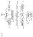
- FIG. 2is a diagram of the interface device used in the system of FIG. 1 .
- the interface device 140includes a network interface 200 (which can be a Wide Area Network (WAN) interface) that can access the network 110 , which in an exemplary embodiment, supports DSL and frame relay.
- the network interface 200includes DSL logic 210 and frame relay logic 220 .
- other interface logiccan be supported, such as Fractional T1 and Full T1 WAN interface.
- the interface device 140also houses the following components: management logic 230 , signal/bearer conversion logic 240 , voice port logic 250 , and data port logic 260 . It is appreciated that the interface device 140 can include other logic than that illustrated in FIG. 2 that aid in the reception, processing, and/or transmission of data.
- DSL logic 210can include one or more DSL ports. In an exemplary embodiment, the DSL logic 210 can also has one or more RJ-11 interfaces.
- the DSL logic 210supports standard DSL protocols for communicating with digital subscriber line access multiplexers (DSLAMs), such as an integrated services digital network (ISDN) digital subscriber line (IDSL) signaling protocol, a symmetric digital subscriber line (SDSL) signaling protocol, and a Global Standard High-bit-rate digital subscriber line (G.SHDSL) signaling protocol, and the like.
- DSL logic 210can support Asymmetrical DSL (ADSL), as described in American National Standards Institute (ANSI) T1E1.413.
- ADSLAsymmetrical DSL
- ANSIAmerican National Standards Institute
- Frame relay logic 220can include one or more frame relay ports. According to one embodiment of the present invention, the frame relay logic 220 can include one or more digital signal 1 (DS1) ANSI T1.102 electrical line rate interfaces that support fractional T1 or full T1 line rates.
- DS1digital signal 1
- Management logic 230manages operation of the interface device 140 , and supports security and Quality of Service (QoS) functions for the interface device 140 .
- the management logic 230also provides for secure methods of file transfer, which can be used for the purpose of application upgrades, log downloads, etc.
- the data port logic 260provides data connectivity to the customer devices 130 , such as a personal computer or other SIP-enabled station, as noted earlier.
- the physical connectionsupports Ethernet connections to the personal computer or to the local area network (LAN) 150 within the customer premise.
- the data port logic 260also supports Internet Protocol (IP) Version 4 (and Version 6). Additionally, the logic 260 supports Dynamic Host Configuration Protocol as defined in IETF RFC 2131, and multiple DNS entries. That is, if the primary DNS server does not respond to a DNS request, a secondary DNS server is queried.
- the interface device 140also provides routing functions for data and voice traffic. For example, the device 140 supports static routing, using Open Shortest Path First (OSPF). In addition, the device 140 provides Routing Information Protocol (RIP) Version 2 for Fractional T1 and Full T1 WAN interface and RIP Version 2 for DSL WAN interface.
- OSPFOpen Shortest Path First
- RIPRouting Information Protocol
- the interface device 140also supports trunk group-based routing; that is, routing based on trunk group prefix digits that are prepended by a Network Server (NS)/Redirect Server (RS) to the Request URI.
- a SIP Proxy Server(not shown), which is accessible by the interface device 140 , is made up of two servers the Network Server (NS) and Redirect Server (RS).
- the NSacts as both a server and a client for the purpose of making requests on behalf of other clients. Requests are serviced internally or by passing them, possibly after translation, to other servers.
- a proxyinterprets, and, if necessary, rewrites a request message before forwarding it.
- the RSaccepts a SIP request, maps the address into zero or more new addresses and returns these addresses to the client.
- the RSalso can be viewed as a location server where information about a possible terminating location could be obtained.
- Trunk group-based routinginvolves mapping and manipulating called party identity between a circuit-switched telephony domain (e.g., PBX) and the IP domain (as more fully described in FIGS. 8 and 9 ).
- the interface device 140selects an outgoing trunk group to a PBX based on the first four-digits in the Request-URI, for example. These four digits are referred to as a “trunk group prefix” and are prepended to the called number by the NS/RS.
- An outgoing trunk group to the PBXcan be selected, based on a variable-length, alphanumeric trunk group prefix in the Request-URI (Uniform Resource Identifier).
- the interface device 140can either delete or not delete the trunk group prefix from the called number string of the outgoing PRI or CAS call setup message.
- the interface device 140can configure the Called Party Number's Type of Number (TON)/Nature of Address (NOA) on a per-trunk group basis, on calls terminating to a PRI trunk group. Also, the TON/NOA can be based upon the digit stream following the trunk group prefix, on calls terminating to a PRI trunk group.
- the various logic 210 , 220 , 230 , 240 , 250 , and 260 within the interface device 140can include hardware, such as an application specific integrated circuit or a field programmable gate array, software, or a combination of hardware and software.
- the interface device 140is not limited to any specific combination of hardware circuitry and software.
- FIG. 3is a diagram of the management logic employed in the interface device of FIG. 2 .
- Management logic 230supports numerous functions through the following components: firewall logic 310 , QoS management logic 320 , a clock 330 , an echo canceller 340 , network management logic 350 , and network address translation (NAT)/port address translation (PAT) logic 360 . It is appreciated that management logic 230 can include other components that aid in the reception, processing, and/or transmission of data.
- the firewall logic 310provides packet filtering capabilities. Such filtering can be based on a set of rules that causes firewall logic 310 to perform a particular action on incoming traffic based on source Internet Protocol (IP) address, source transport address, destination IP address, destination transport address, and the like.
- IPInternet Protocol
- the actionincludes, for example, permitting the received traffic to be forwarded to the customer devices 130 or discarding the traffic in the event that incoming traffic fails to satisfy the set of rules associated with the firewall logic 310 .
- the firewall logic 310can execute one or more dynamic rule sets for media based on SIP signaling.
- the QoS management logic 320provides QoS services (e.g., classification, scheduling, policing, etc.) for the interface device 140 .
- the QoS servicescan include classifying incoming traffic flows, such as real-time transport protocol flows, based, for example, on packet header information (or other information).
- the QoS management logic 320classifies based on IP Type of Service bits, and supports a multi-field classifier.
- the logic 320can classify packets of an RTP flow.
- the classificationcan also be performed at the application layer (e.g., Layer 7 of the Open Systems Interconnection (OSI) model) to accommodate application protocols, such as File Transfer Protocol (FTP), that negotiate additional dynamic flows that are subject to static bandwidth policy.
- the QoS management logic 320can mark 802.1p priority bits based on the classification criteria.
- the QoS management logic 320can implement RFC 2686 Multi-Class Extension to Multi-Link Point-to-Point Protocol (PPP). Accordingly, the interface device 140 can map Differentiated Services bits, or more specifically Type of Service bits, to specific classes and can fragment both UDP and TCP packets based on that class.
- PPPPoint-to-Point Protocol
- the QoS management logic 320can also implement class-based scheduling with priority queuing. Scheduling provides low delay, low delay variation, and low loss rate for VOIP flows, while not “starving out” other application flows. Thus, fair sharing within a class is also provided by the interface device 140 . That is, sharing of bandwidth is made fair such that the first flow within a class does not starve out other flows within the same class. Additionally, the interface device 140 implements a per flow admission control capability that denies admission of new flows when a flow limit for a class is reached. This capability allows restriction of voice calls to an upper limit.
- the QoS management logic 320can remark new flows that violate upper flow limits to different TOS markings or DSCP such that flows above the upper limit are mapped to a lower priority class.
- the QoS management logic 320also supports setting or tuning of queue depth within the priority queue to minimize delay variation.
- the QoS management logic 320may also provide reporting capabilities, such as providing bandwidth usage reports, statistics on the number of dropped packets on a flow or class basis, traffic reports, such as traffic breakdown by user, by site, by network connection, etc., or other reports of interest to the customer.
- reporting capabilitiessuch as providing bandwidth usage reports, statistics on the number of dropped packets on a flow or class basis, traffic reports, such as traffic breakdown by user, by site, by network connection, etc., or other reports of interest to the customer.
- a clock 330provides a reference clock signal for use by the interface device 140 .
- the clock 330may derive the reference clock signal from selected interfaces and/or from external timing interfaces (e.g., from an external DS1 timing interface).
- the interface device 140may use the reference clock signal for synchronization purposes and/or for jitter/wander requirements.
- Echo canceller 340provides echo control/cancellation for the interface device 140 .
- the echo canceller 340includes an International Telecommunications Union (ITU) G.168-compliant echo canceller.
- ITUInternational Telecommunications Union
- the network management logic 350provides fault management, configuration management, accounting, performance management, and security functions for the interface device 140 .
- fault managementthe network management logic 350 detects, logs, and notifies users of, and, if possible, repairs problems to keep the network running effectively.
- the network management logic 350can include alarm mechanisms to alert users or network administrators of, for example, system faults, network interface problems, hardware/software failures, and the like.
- the network management logic 350may log protocol events (for both circuit-switched and SIP protocols) as they relate to call processing, call failures, and call abandonments with an explanation of the cause, and incoming messages that are incorrectly formatted, timestamp the logs, and monitor the number of active calls on the interface device 140 at any given time.
- the network management logic 350may monitor network and the interface device 140 configuration information so that any effects on network operation of various hardware and software elements can be tracked and managed.
- the network management logic 350adheres to the standard SIP Management Information Base (MIB) User-Agent requirements.
- MIBSIP Management Information Base
- the network management logic 350can measure network-utilization parameters so that individual or groups of users on the network can be regulated appropriately. This information may be used for creation of billing information, as well as usage patterns.
- the network management logic 350may measure and make available aspects of network performance, such as network throughput, user response times, and line utilization, so that inter-network performance can be maintained at an acceptable level.
- the network management logic 350provides users with the ability to view the status of various interface device 140 components, such as Foreign Exchange Station (FXS)/Foreign Exchange Office (FXO) voice ports, trunk groups, and the like, and to enable and disable components of the interface device 140 .
- the network management logic 350can also provide real-time statistics and counters related to a traffic stream. The statistics and counters may track jitter, latency, lost packets, error packets, packets that are out of sequence, dialed call completions, and etc.
- the interface device 140supports various file transfer mechanisms. For instance, to provide for secure methods of file transfer, for the purpose of application upgrades, log downloads, etc., the device 140 can provide the following Secure Socket Layer (SSL) web-based upload/download mechanisms: Secure Copy, SSH—Remote Console, and Secure File Transfer Protocol (FTP).
- SSLSecure Socket Layer
- FTPSecure File Transfer Protocol
- the network management logic 350may control access to network resources so that the customer's network cannot be compromised, and those without appropriate authorization cannot access sensitive information.
- the network management logic 350rejects or allows messages based on the IP address of the sender.
- the network management logic 350may also provide the ability to remotely control and configure the interface device 140 .
- the network management logic 350may allow the interface device 140 to be controlled and/or configured via a serial connection.
- the network management logic 350may allow for the creation, modification, and editing of bandwidth policy, or the addition or modification of customer features and/or services.
- Access to the interface device 140may occur via a secure terminal emulation protocol, such as Secure Shell (SSH).
- SSHSecure Shell
- NAT/PAT logic 360provides security and signal processing for traffic transmitted between customer devices 130 and network 110 .
- the NAT/PAT logic 360also provides topology hiding capabilities, as illustrated in FIG. 4 .
- FIG. 4is a diagram showing a topology hiding operation of the network address translation (NAT)/port address translation (PAT) logic of FIG. 3 .
- the NAT/PAT logic 360hides the topology of the internal network 150 with the customer premise from external devices by translating network addresses and/or port addresses associated with the customer devices 130 to one external address (e.g., registered, global IP address).
- SIPSession Initiation Protocol
- SDPsession description protocol
- RTCPreal-time transport control protocol
- the NAT/PAT logic 360modifies NAT, PAT, or secure flow processing (SFP) functionality to hide all internal addresses that may be embedded within SIP and RTCP packets with the external IP addresses as they traverse the interface device 140 .
- SFPsecure flow processing
- the NAT/PAT logic 360dynamically assigns network addresses and port addresses to customer devices 130 .
- the NAT/PAT logic 360performs network address and port address translation at, for example, the Session Layer, Presentation Layer, and/or Application Layer.
- a signal/bearer conversion logic 240performs all necessary conversions for traffic transmitted between management logic 230 and voice port logic 250 .
- the signal/bearer conversion logic 240performs signaling protocol conversion for traffic transmitted between a telephone switch (e.g., PBX switch) and the management logic 230 .
- the signaling protocol conversioncan include, for example, conversions between the SIP signaling protocol and the Integrated Services Digital Network (ISDN) signaling protocol.
- the signal/bearer conversion logic 240may also perform bearer channel conversion for traffic transmitted between an analog telephone and management logic 230 .
- the bearer channel conversioncan include, for example, conversions between an RTP format and an analog format.
- Voice port logic 250includes one or more ports for supporting Foreign Exchange Station (FXS) and Foreign Exchange Office (FXO) voice lines and fractional T1 and full T1 voice trunks.
- the voice port logic 250provides one or more RJ-11 FXS voice port electrical line rate interfaces, one or more RJ-11 FXO voice port electrical line rate interfaces, and one or more DS1 ANSI T1.102 electrical line rate interfaces.
- the voice port logic 250supports various signaling protocols, such as Foreign Exchange Station Loop Start (FXSLS), Foreign Exchange Office Loop Start (FXOLS), Foreign Exchange Station Ground Start (FXSGS), Foreign Exchange Office Ground Start (FXOGS), American National Standards Institute (ANSI) PRI (Q.931) signaling protocol, and the like.
- Voice port logic 250may also support Channel Associated Signaling (CAS) trunk types, dual tone multi-frequency (DTMF) dialed number transmittal and receipt over CAS trunk groups, multi-frequency (MF) dialed number transmittal and receipt over CAS trunk groups, sub-T1-size CAS trunk groups, and etc.
- CASChannel Associated Signaling
- DTMFdual tone multi-frequency
- MFmulti-frequency
- FIG. 5is a diagram of the voice port logic of FIG. 2 .
- the voice port logic 250can include voice ports 510 and voice trunks 520 .
- the voice ports 510in an exemplary embodiment, support FXS/FXO voice lines for analog telephones.
- the voice trunks 520provide fractional T1 and/or full T1 line rates, and connect to one or more PBXs.
- the data port logic 260in an exemplary embodiment, includes one or more ports for supporting 1 ⁇ N base-T Ethernet (where N equals, 10, 100, 1000, etc.).
- Nequals, 10, 100, 1000, etc.
- the data port logic 260supports 10 Mb/s half duplex Ethernet, 10 Mb/s full duplex Ethernet, 100 Mb/s half duplex Ethernet, 100 Mb/s full duplex Ethernet, 10/100 half/full auto-negotiation, wireless networking, and virtual local area network (VLAN) tagging.
- VLANvirtual local area network
- FIG. 6is a flowchart of a process for routing traffic from a network through the interface device of FIG. 2 .
- Processingbegins with the interface device 140 receiving traffic from a user device 120 via network 110 (step 610 ).
- the received trafficis SIP traffic; however, it is contemplated that the interface device 140 can operate with other traffic types (e.g., ITU H.323).
- the trafficis received via DSL logic 210 or frame relay logic 220 and may, for example, be in the form of packets.
- the trafficmay be filtered via firewall logic 310 ( FIG. 3 ) (step 620 ).
- the firewall logic 310then examines the incoming traffic and determines, based on a predetermined set of rules, whether to discard the traffic or forward the traffic toward its destination.
- the firewall logic 310can filter traffic based on source IP address, source transport address, destination IP address, and destination transport address.
- the interface device 140then performs QoS processing on the traffic, per step 630 .
- the QoS management logic 320classifies the traffic and schedules the traffic according to the classification.
- the interface device 140processes the traffic to put the traffic in a format suitable for the particular destination customer device 130 , as in step 640 .
- the interface device 140performs any necessary bearer channel conversion or signaling conversion. In those situations where the received traffic is destined for a SIP-based device, such as a SIP telephone, signal processing may not be necessary.
- the interface device 140then transmits the traffic to the appropriate customer device 130 (step 650 ).
- the trafficis transmitted via voice port logic 250 or data port logic 260 , based upon the particular customer device 130 to which the traffic is destined. If, for example, the traffic is destined for an analog telephone or a PBX, the interface device 140 transmits the traffic through voice port logic 250 . If, on the other hand, the traffic is destined to a SIP device, such as a SIP telephone, the interface device 140 transmits the traffic through the data port logic 260 .
- FIG. 7is a flowchart of a process for routing traffic from one or more customer devices through the interface device of FIG. 2 .
- the interface device 140receives traffic from one or more customer devices 130 .
- the trafficmay be received via voice port logic 250 or data port logic 260 and may, for example, be in the form of packets, analog signals, or ISDN signals.
- the interface device 140processes the traffic in a form suitable for transmission over the network 110 (step 720 ). For example, if the traffic is received via the voice port logic 250 , the interface device 140 performs the necessary bearer channel conversion or signaling conversion. In those situations in which the traffic is received via the data port logic 260 , signal processing may not be necessary since the traffic may already be in an appropriate form for transmission to the network 110 .
- the interface device 140then performs QoS processing on the traffic.
- the QoS management logic 320classifies the traffic and schedules such traffic for transmission.
- the interface device 140translates a source address associated with the received traffic to a network address.
- This address translationcan be NAT or PAT, thereby acting to hide addresses of customer devices 130 from user devices 120 connected to network 110 .
- the address translationcan be performed at the Session Layer, Presentation Layer, and/or Application Layer.
- the interface device 140transmits the traffic to the network 110 , per step 750 .
- the trafficis transmitted via DSL logic 210 or frame relay logic 220 and may be formatted accordingly, based upon the particular port (i.e., DSL or frame relay) from which the traffic is transmitted.
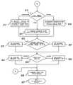
- FIGS. 8 a and 8 bare a flowchart of a process for converting Time Division Multiplexing (TDM) signaling to Session Initiation Protocol (SIP) signaling to support call processing, according to an embodiment of the present invention.
- This processsupports the mapping of originating caller identity (calling party) between a circuit-switched telephone network domain (e.g., PBX network) and the IP domain.
- a circuit-switched telephone network domaine.g., PBX network
- the interface device 140receives a call that is destined for a SIP client (e.g., device 130 ) over a PRI trunk. Accordingly, the interface device 140 prepares a SIP INVITE message, per step 803 . Next, it is determined whether the call set up message specifies a calling party number, as in step 805 . If a calling party number is provided, the interface device 140 obtains, as in step 807 , the appropriate address digits from the calling party number. The interface device 140 then appends, as in step 809 , a Remote-Party-ID (RPID) header to the SIP INVITE message, wherein the header information includes ADDR-SPEC, RPI-SCREEN, and RPI-PRIVACY parameters.
- RPIDRemote-Party-ID
- the interface device 140populates the From header with a configurable, alphanumeric value (e.g., “unknown” ⁇ sip:unknown@ xxxx.xxx>) when it receives signaling of type CAS, for example.
- a configurable, alphanumeric valuee.g., “unknown” ⁇ sip:unknown@ xxxx.xxx>
- the From headeris similarly populated when the device 140 receives signaling of type PRI with no Calling Party Number information element (IE) present in a SETUP message.
- IECalling Party Number information element
- the valuefollows the normal SIP rules for the From header (e.g., IPv4 address, domain name, etc.).
- the interface device 140populates the From header with a configurable, alphanumeric value (i.e.,“anonymous” ⁇ sip:anonymous@ xxxx.xxx>) when the device 140 receives PSTN signaling of type PRI with Calling Party Number IE present in the SETUP message, and the Presentation Indicator is Restricted.
- a configurable, alphanumeric valuei.e.,“anonymous” ⁇ sip:anonymous@ xxxx.xxx>
- the interface device 140When Calling Party Number digits are mapped to the From header, the interface device 140 is able to configure a country code against the originating trunk group that can be used in formatting the From header.
- the following rulesapply for formatting the user part of the SIP URL in the From header, using the received TON/NOA along with the configured country code, as shown in Table 1, below.
- the interface device 140per step 811 , identifies the trunk group of the incoming call, and subsequently determines the country code corresponding to the identified trunk group (step 813 ). As shown in FIG. 8 b , the interface device 140 next determines whether the call is a national, international, or some other call based on the type of number and nature of the address, as in step 815 . Per the rules enumerated in Table 1, if the call is an international call, the ADDR-SPEC parameter in the RPID header is set, for example, to a “+” sign followed by the country code and the received address digits, per step 817 .
- the RPID headeris set, as in step 819 , only with the “+” sign followed by the received address digits.
- the ADDR-SPEC parameter in the RPID headeris simply populated with the received address digits (step 821 ).
- step 823the interface device 140 checks whether the SCREEN INDICATOR parameter is set to “User Provided” or “User Provided, Verified, and Failed.” If none of these conditions are satisfied, the RPI-SCREEN parameter is set to “YES” (step 825 ); otherwise, the RPI-SCREEN parameter is set to “NO” (step 827 ). Thereafter, the interface device 140 examines the presentation indicator, as in step 829 ; if the indicator specifies a restriction, then the RPI-PRIVACY parameter is set to “YES” (step 831 ).
- the interface device 140per step 833 , sets the RPI-PRIVACY parameter to “NO.”
- the remaining INVITE messageis prepared, as in step 835 .
- the SIP INVITE messageis transmitted to the SIP client.
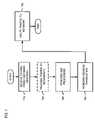
- FIGS. 9 a and 9 bare a flowchart of a process for converting Session Initiation Protocol (SIP) signaling to Time Division Multiplexing (TDM) signaling to support call processing, according to an embodiment of the present invention.
- the interface device 140receives a SIP INVITE message from a customer device 130 that is a SIP client.
- the INVITE messagepertains to a call that is to be transported over a PRI trunk group.
- the interface device 140Upon receipt of such a message, the interface device 140 then prepares a SETUP message, as in step 903 , with a called party number information element (IE).
- IEcalled party number information element
- the interface device 140determines whether the SIP INVITE message contains a Remote-Party-ID (RPID) header, as in step 905 .
- RPIDRemote-Party-ID
- the Remote-Party-ID headeris employed for the reliable transport of Calling Party Number information to and from a telephone switch (e.g., PBX).
- the interface device 140generates a Remote-Party-ID header and populates the ADDR-SPEC parameter with the Calling Party Number address digits, when the device 140 receives PSTN signaling of type PRI with Calling Party Number IE present in the SETUP message.
- the interface device 140can configure a country code against the originating trunk group that can be used in formatting the Remote-Party-ID header. According to an embodiment of the present invention, the following rules apply for formatting the ADDR-SPEC parameter, using the received TON/NOA together with the configured country code (Table 2).
- the device 140examines whether the RPI-SCREEN field is set to “YES,” per step 907 . If not, the interface device 140 checks whether the message can be mapped to a calling party number (step 909 ). That is, the interface device 140 maps the screening indicator to the RPI-screen parameter. Screening indicator values of “USER PROVIDED” and “USER PROVIDED, VERIFIED, AND FAILED” maps to RPI-screen value of “NO.” All other screening indicators are mapped to RPI-screen value of “YES.”
- the interface device 140maps the RPID header from the SIP INVITE message into a calling party number of PRI Setup message. If the Remote-Party-ID header is received, and it is determined that it should be mapped to Calling Party Number, then the interface device 140 sets the privacy indicator and screening indicator in the outgoing SETUP Calling Party Number IE according to Table 3:
- the “Screening Indicator” field within the PRI Setup messageis set to “Network Provided,” per step 913 .
- the interface device 140checks the value of the RPI-SCREEN field, as in step 915 , whereby if the field specifies “OFF” or “NAME,” the Privacy Indicator in the Setup message is set to “Presentation Allowed” (step 917 ). If the RPI-SCREEN value specifies “Full” or “URI,” then the Privacy Indicator is set to “Presentation Restricted.”
- step 921the interface device 140 determines the country code that is configured for the terminating trunk group.
- the ADDR-SPEC parameteris obtained from the RPID header of the SIP INVITE message, wherein the interface device 140 inspects whether the ADDR-SPEC is an E.164 number (step 925 ). If the ADDR-SPEC field does not specify an E.164 number, the Type of Number (TON)/Nature of Address (NOA) field in the Setup message is populated with a default value associated with the terminating trunk group, per step 927 .
- the interface device 140sets the TON/NOA in the outgoing SETUP Calling Party Number IE per Table 4 below:
- the device 140compares whether the country code for the trunk group matches the country code information stored in the ADDR-SPEC field (step 929 ). If there is a match, per step 931 , the TON/NOA field is set to “National,” and the country code is removed from the digits in the calling party number. If there is no match, the TON/NOA field is set to “International,” as in step 933 . Thereafter, the Setup message is transmitted, per step 935 .
- the integrated SIP-enabled CPE device 140provides customers with multitude of voice and data services, including a firewall, QoS processing, routing capabilities, and Ethernet switching functionality, for example. This single CPE device allows customers to update or add new features and/or services without having to continually purchase new hardware to obtain these features/services.
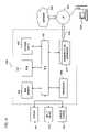
- FIG. 10illustrates a computer system 1000 upon which an embodiment according to the present invention can be implemented.
- the computer system 1000includes a bus 1001 or other communication mechanism for communicating information and a processor 1003 coupled to the bus 1001 for processing information.
- the computer system 1000also includes main memory 1005 , such as a random access memory (RAM) or other dynamic storage device, coupled to the bus 1001 for storing information and instructions to be executed by the processor 1003 .
- Main memory 1005can also be used for storing temporary variables or other intermediate information during execution of instructions by the processor 1003 .
- the computer system 1000may further include a read only memory (ROM) 1007 or other static storage device coupled to the bus 1001 for storing static information and instructions for the processor 1003 .
- ROMread only memory
- a storage device 1009such as a magnetic disk or optical disk, is coupled to the bus 1001 for persistently storing information and instructions.
- the computer system 1000may be coupled via the bus 1001 to a display 1011 , such as a cathode ray tube (CRT), liquid crystal display, active matrix display, or plasma display, for displaying information to a computer user.
- a display 1011such as a cathode ray tube (CRT), liquid crystal display, active matrix display, or plasma display
- An input device 1013is coupled to the bus 1001 for communicating information and command selections to the processor 1003 .
- a cursor control 1015is Another type of user input device, such as a mouse, a trackball, or cursor direction keys, for communicating direction information and command selections to the processor 1003 and for controlling cursor movement on the display 1011 .
- the SIP client and servercan be provided by the computer system 1000 in response to the processor 1003 executing an arrangement of instructions contained in main memory 1005 .
- Such instructionscan be read into main memory 1005 from another computer-readable medium, such as the storage device 1009 .
- Execution of the arrangement of instructions contained in main memory 1005causes the processor 1003 to perform the process steps described herein.
- processors in a multi-processing arrangementmay also be employed to execute the instructions contained in main memory 1005 .
- hard-wired circuitrymay be used in place of or in combination with software instructions to implement the embodiment of the present invention.
- reconfigurable hardwaresuch as Field Programmable Gate Arrays (FPGAs) can be used, in which the functionality and connection topology of its logic gates are customizable at run-time, typically by programming memory look up tables.
- FPGAsField Programmable Gate Arrays
- the computer system 1000also includes a communication interface 1017 coupled to bus 1001 .
- the communication interface 1017provides a two-way data communication coupling to a network link 1019 connected to a local network 1021 .
- the communication interface 1017may be a digital subscriber line (DSL) card or modem, an integrated services digital network (ISDN) card, a cable modem, a telephone modem, or any other communication interface to provide a data communication connection to a corresponding type of communication line.
- communication interface 1017may be a local area network (LAN) card (e.g., for EthernetTM or an Asynchronous Transfer Model (ATM) network) to provide a data communication connection to a compatible LAN.
- LANlocal area network
- Wireless linkscan also be implemented.
- communication interface 1017sends and receives electrical, electromagnetic, or optical signals that carry digital data streams representing various types of information.
- the communication interface 1017can include peripheral interface devices, such as a Universal Serial Bus (USB) interface, a PCMCIA (Personal Computer Memory Card International Association) interface, etc.
- USBUniversal Serial Bus
- PCMCIAPersonal Computer Memory Card International Association
- the network link 1019typically provides data communication through one or more networks to other data devices.
- the network link 1019may provide a connection through local network 1021 to a host computer 1023 , which has connectivity to a network 1025 (e.g., a wide area network (WAN) or the global packet data communication network now commonly referred to as the “Internet”) or to data equipment operated by a service provider.
- the local network 1021 and the network 1025both use electrical, electromagnetic, or optical signals to convey information and instructions.
- the signals through the various networks and the signals on the network link 1019 and through the communication interface 1017 , which communicate digital data with the computer system 1000are exemplary forms of carrier waves bearing the information and instructions.
- the computer system 1000can send messages and receive data, including program code, through the network(s), the network link 1019 , and the communication interface 1017 .
- a server(not shown) might transmit requested code belonging to an application program for implementing an embodiment of the present invention through the network 1025 , the local network 1021 and the communication interface 1017 .
- the processor 1003may execute the transmitted code while being received and/or store the code in the storage device 1009 , or other non-volatile storage for later execution. In this manner, the computer system 1000 may obtain application code in the form of a carrier wave.
- Non-volatile mediainclude, for example, optical or magnetic disks, such as the storage device 1009 .
- Volatile mediainclude dynamic memory, such as main memory 1005 .
- Transmission mediainclude coaxial cables, copper wire and fiber optics, including the wires that comprise the bus 1001 . Transmission media can also take the form of acoustic, optical, or electromagnetic waves, such as those generated during radio frequency (RF) and infrared (IR) data communications.
- RFradio frequency
- IRinfrared
- Computer-readable mediainclude, for example, a floppy disk, a flexible disk, hard disk, magnetic tape, any other magnetic medium, a CD-ROM, CDRW, DVD, any other optical medium, punch cards, paper tape, optical mark sheets, any other physical medium with patterns of holes or other optically recognizable indicia, a RAM, a PROM, and EPROM, a FLASH-EPROM, any other memory chip or cartridge, a carrier wave, or any other medium from which a computer can read.
- a floppy diska flexible disk, hard disk, magnetic tape, any other magnetic medium, a CD-ROM, CDRW, DVD, any other optical medium, punch cards, paper tape, optical mark sheets, any other physical medium with patterns of holes or other optically recognizable indicia, a RAM, a PROM, and EPROM, a FLASH-EPROM, any other memory chip or cartridge, a carrier wave, or any other medium from which a computer can read.
- the instructions for carrying out at least part of the present inventionmay initially be borne on a magnetic disk of a remote computer.
- the remote computerloads the instructions into main memory and sends the instructions over a telephone line using a modem.
- a modem of a local computer systemreceives the data on the telephone line and uses an infrared transmitter to convert the data to an infrared signal and transmit the infrared signal to a portable computing device, such as a personal digital assistant (PDA) or a laptop.
- PDApersonal digital assistant
- An infrared detector on the portable computing devicereceives the information and instructions borne by the infrared signal and places the data on a bus.
- the busconveys the data to main memory, from which a processor retrieves and executes the instructions.
- the instructions received by main memorycan optionally be stored on storage device either before or after execution by processor.
Landscapes
- Engineering & Computer Science (AREA)
- Signal Processing (AREA)
- Computer Networks & Wireless Communication (AREA)
- Multimedia (AREA)
- Business, Economics & Management (AREA)
- General Business, Economics & Management (AREA)
- General Engineering & Computer Science (AREA)
- Telephonic Communication Services (AREA)
- Data Exchanges In Wide-Area Networks (AREA)
Abstract
Description
| TABLE 1 | |
| Received | |
| NOA/TON | User Part of From Header |
| National | E.164 format: ‘+’ followed by a configurable country |
| code, followed by received address digits | |
| International | E.164 format: ‘+’ followed by received address digits |
| All other values | Non-E.164 format: address digits |
| TABLE 2 | |
| Received | Outgoing ADDR-SPEC Parameter of |
| NOA/TON | Remote-Party-ID (RPID) |
| National | E.164 format: ‘+’ followed by a configurable country |
| code, followed by received address digits | |
| International | E.164 format: ‘+’ followed by received address digits |
| All other values | Non-E.164 format: address digits |
| TABLE 3 | ||||
| Received RPI- | Outgoing Privacy | Outgoing Screening | ||
| screen | Indicator | Indicator | ||
| Full | Presentation Restricted | Network Provided | ||
| URI | Presentation Restricted | Network Provided | ||
| Off | Presentation Allowed | Network Provided | ||
| Name | Presentation Allowed | Network Provided | ||
| TABLE 4 | |
| Received | |
| ADDR-SPEC | |
| Digit Format | Outgoing TON/NOA |
| E.164 | International - if the configured country code does |
| not match the first digits of the ADDR-SPEC | |
| E.164 | National - if the configured country code does match |
| the first digits of the ADDR-SPEC (The country code | |
| should be stripped from the address digits in this | |
| scenario). | |
| Non-E.164 | Per-trunk group configurable default value |
Claims (32)
Priority Applications (2)
| Application Number | Priority Date | Filing Date | Title |
|---|---|---|---|
| US10/800,394US7020130B2 (en) | 2003-03-13 | 2004-03-12 | Method and apparatus for providing integrated voice and data services over a common interface device |
| US11/359,422US7924818B2 (en) | 2003-03-13 | 2006-02-23 | Method and apparatus for providing integrated voice and data services over a common interface device |
Applications Claiming Priority (2)
| Application Number | Priority Date | Filing Date | Title |
|---|---|---|---|
| US45447003P | 2003-03-13 | 2003-03-13 | |
| US10/800,394US7020130B2 (en) | 2003-03-13 | 2004-03-12 | Method and apparatus for providing integrated voice and data services over a common interface device |
Related Child Applications (1)
| Application Number | Title | Priority Date | Filing Date |
|---|---|---|---|
| US11/359,422ContinuationUS7924818B2 (en) | 2003-03-13 | 2006-02-23 | Method and apparatus for providing integrated voice and data services over a common interface device |
Publications (2)
| Publication Number | Publication Date |
|---|---|
| US20040213150A1 US20040213150A1 (en) | 2004-10-28 |
| US7020130B2true US7020130B2 (en) | 2006-03-28 |
Family
ID=33029883
Family Applications (2)
| Application Number | Title | Priority Date | Filing Date |
|---|---|---|---|
| US10/800,394Expired - LifetimeUS7020130B2 (en) | 2003-03-13 | 2004-03-12 | Method and apparatus for providing integrated voice and data services over a common interface device |
| US11/359,422Active2027-09-14US7924818B2 (en) | 2003-03-13 | 2006-02-23 | Method and apparatus for providing integrated voice and data services over a common interface device |
Family Applications After (1)
| Application Number | Title | Priority Date | Filing Date |
|---|---|---|---|
| US11/359,422Active2027-09-14US7924818B2 (en) | 2003-03-13 | 2006-02-23 | Method and apparatus for providing integrated voice and data services over a common interface device |
Country Status (3)
| Country | Link |
|---|---|
| US (2) | US7020130B2 (en) |
| EP (1) | EP1604270A4 (en) |
| WO (1) | WO2004084026A2 (en) |
Cited By (35)
| Publication number | Priority date | Publication date | Assignee | Title |
|---|---|---|---|---|
| US20020150091A1 (en)* | 2001-04-17 | 2002-10-17 | Jussi Lopponen | Packet mode speech communication |
| US20040120474A1 (en)* | 2001-04-17 | 2004-06-24 | Jussi Lopponen | Packet mode speech communication |
| US20060140178A1 (en)* | 2004-12-27 | 2006-06-29 | Wei-Yuan Cheng | Method for connecting routing device in existing wiring |
| US20060153242A1 (en)* | 2003-03-13 | 2006-07-13 | Krause Joel M | Method and apparatus for providing integrated voice and data services over a common interface device |
| US20060203749A1 (en)* | 2005-03-09 | 2006-09-14 | Plustek Inc | Multimedia conference system and method which enables communication between private network and Internet |
| US20070070982A1 (en)* | 2005-09-29 | 2007-03-29 | Marian Croak | Method and apparatus for tagging customer specific signaling packets |
| US20070147369A1 (en)* | 2003-03-13 | 2007-06-28 | Serconet Ltd. | Telephone system having multiple sources and accessories therefor |
| US20070209067A1 (en)* | 2006-02-21 | 2007-09-06 | Fogel Richard M | System and method for providing security for SIP-based communications |
| US20070245412A1 (en)* | 2006-04-13 | 2007-10-18 | Directpacket Research, Inc. | System and method for a communication system |
| US20070242694A1 (en)* | 2006-04-13 | 2007-10-18 | Directpacket Research, Inc. | System and method for cross protocol communication |
| US20070242696A1 (en)* | 2006-04-13 | 2007-10-18 | Directpacket Research, Inc. | System and method for traversing a firewall with multimedia communication |
| US20080013529A1 (en)* | 2000-04-18 | 2008-01-17 | Serconet Ltd. | Telephone communication system over a single telephone line |
| US20080117091A1 (en)* | 2004-11-08 | 2008-05-22 | Serconet Ltd. | Outlet with analog signal adapter, a method for use thereof and a network using said outlet |
| US20080120663A1 (en)* | 2001-10-11 | 2008-05-22 | Serconet Ltd. | Outlet with analog signal adapter, a method for use thereof and a network using said outlet |
| US20080137649A1 (en)* | 2006-12-07 | 2008-06-12 | Nortel Networks Limited | Techniques for implementing logical trunk groups with session initiation protocol (sip) |
| US20080240087A1 (en)* | 2006-12-13 | 2008-10-02 | Verizon Services Corp. | Hybrid internet protocol based session control protocol and pstn communications |
| US20090006630A1 (en)* | 2007-06-14 | 2009-01-01 | Hitachi Communication Technologies, Ltd. | Sip converter |
| US20090086733A1 (en)* | 2004-03-29 | 2009-04-02 | Conexant Systems, Inc. | Compact Packet Switching Node Storage Architecture Employing Double Data Rate Synchronous Dynamic RAM |
| US20090094531A1 (en)* | 2007-10-05 | 2009-04-09 | Microsoft Corporation | Telephone call as rendezvous mechanism for data sharing between users |
| US7542554B2 (en) | 2001-07-05 | 2009-06-02 | Serconet, Ltd | Telephone outlet with packet telephony adapter, and a network using same |
| US7594259B1 (en)* | 2004-09-15 | 2009-09-22 | Nortel Networks Limited | Method and system for enabling firewall traversal |
| WO2010071721A1 (en) | 2008-12-18 | 2010-06-24 | Exxonmobile Upstream Research Company | Sediment transport by fully developed turbulent flows |
| US20100205313A1 (en)* | 2009-02-06 | 2010-08-12 | Sagem-Interstar, Inc. | Scalable NAT Traversal |
| US20110158132A1 (en)* | 2005-09-22 | 2011-06-30 | Verizon Services Organization, Inc. | Method and system for providing call screening in a packet-switched network |
| US8325636B2 (en) | 1998-07-28 | 2012-12-04 | Mosaid Technologies Incorporated | Local area network of serial intelligent cells |
| US8555371B1 (en) | 2009-07-17 | 2013-10-08 | Directpacket Research, Inc. | Systems and methods for management of nodes across disparate networks |
| US8605730B2 (en) | 2006-04-13 | 2013-12-10 | Directpacket Research, Inc. | System and method for multimedia communication across disparate networks |
| US20140207881A1 (en)* | 2011-01-26 | 2014-07-24 | Ruprecht-Karls-Universitat Heidelberg | Circuit arrangement for connection interface |
| US10986165B2 (en) | 2004-01-13 | 2021-04-20 | May Patents Ltd. | Information device |
| US11330034B1 (en) | 2020-10-27 | 2022-05-10 | T-Mobile Usa, Inc. | Data disruption tracking for wireless networks, such as IMS networks |
| US11343373B1 (en) | 2021-01-29 | 2022-05-24 | T-Mobile Usa, Inc. | Machine intelligent isolation of international calling performance degradation |
| US11729588B1 (en) | 2021-09-30 | 2023-08-15 | T-Mobile Usa, Inc. | Stateless charging and message handling |
| US12156279B1 (en) | 2021-09-13 | 2024-11-26 | T-Mobile Usa, Inc. | Channel quality indication in session initiation protocol signaling |
| US12200592B2 (en) | 2022-03-15 | 2025-01-14 | T-Mobile Usa, Inc. | Automatically identifying a call associated with a wireless telecommunication network as an open-line call |
| US12284582B2 (en) | 2022-03-15 | 2025-04-22 | T-Mobile Usa, Inc. | Inaudibly notifying a caller of a status of an open-line call |
Families Citing this family (112)
| Publication number | Priority date | Publication date | Assignee | Title |
|---|---|---|---|---|
| US6658091B1 (en) | 2002-02-01 | 2003-12-02 | @Security Broadband Corp. | LIfestyle multimedia security system |
| US7701854B2 (en)* | 2003-11-17 | 2010-04-20 | International Business Machines Corporation | Differentiated handling of SIP messages for VoIP call control |
| US11343380B2 (en) | 2004-03-16 | 2022-05-24 | Icontrol Networks, Inc. | Premises system automation |
| US11244545B2 (en) | 2004-03-16 | 2022-02-08 | Icontrol Networks, Inc. | Cross-client sensor user interface in an integrated security network |
| US11316958B2 (en) | 2008-08-11 | 2022-04-26 | Icontrol Networks, Inc. | Virtual device systems and methods |
| US9531593B2 (en) | 2007-06-12 | 2016-12-27 | Icontrol Networks, Inc. | Takeover processes in security network integrated with premise security system |
| US10237237B2 (en) | 2007-06-12 | 2019-03-19 | Icontrol Networks, Inc. | Communication protocols in integrated systems |
| US10380871B2 (en) | 2005-03-16 | 2019-08-13 | Icontrol Networks, Inc. | Control system user interface |
| US10156959B2 (en) | 2005-03-16 | 2018-12-18 | Icontrol Networks, Inc. | Cross-client sensor user interface in an integrated security network |
| US10348575B2 (en) | 2013-06-27 | 2019-07-09 | Icontrol Networks, Inc. | Control system user interface |
| US11677577B2 (en) | 2004-03-16 | 2023-06-13 | Icontrol Networks, Inc. | Premises system management using status signal |
| US8963713B2 (en) | 2005-03-16 | 2015-02-24 | Icontrol Networks, Inc. | Integrated security network with security alarm signaling system |
| US20170118037A1 (en) | 2008-08-11 | 2017-04-27 | Icontrol Networks, Inc. | Integrated cloud system for premises automation |
| US11489812B2 (en) | 2004-03-16 | 2022-11-01 | Icontrol Networks, Inc. | Forming a security network including integrated security system components and network devices |
| US7711796B2 (en) | 2006-06-12 | 2010-05-04 | Icontrol Networks, Inc. | Gateway registry methods and systems |
| US20090077623A1 (en) | 2005-03-16 | 2009-03-19 | Marc Baum | Security Network Integrating Security System and Network Devices |
| US10313303B2 (en) | 2007-06-12 | 2019-06-04 | Icontrol Networks, Inc. | Forming a security network including integrated security system components and network devices |
| US10062273B2 (en) | 2010-09-28 | 2018-08-28 | Icontrol Networks, Inc. | Integrated security system with parallel processing architecture |
| US10522026B2 (en) | 2008-08-11 | 2019-12-31 | Icontrol Networks, Inc. | Automation system user interface with three-dimensional display |
| US9609003B1 (en) | 2007-06-12 | 2017-03-28 | Icontrol Networks, Inc. | Generating risk profile using data of home monitoring and security system |
| US9141276B2 (en) | 2005-03-16 | 2015-09-22 | Icontrol Networks, Inc. | Integrated interface for mobile device |
| US12063220B2 (en) | 2004-03-16 | 2024-08-13 | Icontrol Networks, Inc. | Communication protocols in integrated systems |
| US11113950B2 (en) | 2005-03-16 | 2021-09-07 | Icontrol Networks, Inc. | Gateway integrated with premises security system |
| US10339791B2 (en) | 2007-06-12 | 2019-07-02 | Icontrol Networks, Inc. | Security network integrated with premise security system |
| US10444964B2 (en) | 2007-06-12 | 2019-10-15 | Icontrol Networks, Inc. | Control system user interface |
| US11159484B2 (en) | 2004-03-16 | 2021-10-26 | Icontrol Networks, Inc. | Forming a security network including integrated security system components and network devices |
| US8635350B2 (en) | 2006-06-12 | 2014-01-21 | Icontrol Networks, Inc. | IP device discovery systems and methods |
| US9729342B2 (en) | 2010-12-20 | 2017-08-08 | Icontrol Networks, Inc. | Defining and implementing sensor triggered response rules |
| US10200504B2 (en) | 2007-06-12 | 2019-02-05 | Icontrol Networks, Inc. | Communication protocols over internet protocol (IP) networks |
| US11582065B2 (en) | 2007-06-12 | 2023-02-14 | Icontrol Networks, Inc. | Systems and methods for device communication |
| US11811845B2 (en) | 2004-03-16 | 2023-11-07 | Icontrol Networks, Inc. | Communication protocols over internet protocol (IP) networks |
| US11277465B2 (en) | 2004-03-16 | 2022-03-15 | Icontrol Networks, Inc. | Generating risk profile using data of home monitoring and security system |
| US11368429B2 (en) | 2004-03-16 | 2022-06-21 | Icontrol Networks, Inc. | Premises management configuration and control |
| US11916870B2 (en) | 2004-03-16 | 2024-02-27 | Icontrol Networks, Inc. | Gateway registry methods and systems |
| US10721087B2 (en) | 2005-03-16 | 2020-07-21 | Icontrol Networks, Inc. | Method for networked touchscreen with integrated interfaces |
| JP2007529826A (en) | 2004-03-16 | 2007-10-25 | アイコントロール ネットワークス, インコーポレイテッド | Object management network |
| US11201755B2 (en) | 2004-03-16 | 2021-12-14 | Icontrol Networks, Inc. | Premises system management using status signal |
| US10142392B2 (en) | 2007-01-24 | 2018-11-27 | Icontrol Networks, Inc. | Methods and systems for improved system performance |
| US20070286237A1 (en)* | 2004-08-25 | 2007-12-13 | Signal Networks Pvt. Ltd. | System and method for providing an integrated communications manager |
| US20060052133A1 (en)* | 2004-08-25 | 2006-03-09 | Anand Mallya | System and method for providing an integrated mobile, data and communication manager |
| US7948972B2 (en) | 2004-08-25 | 2011-05-24 | Signal Networks Pvt. Ltd. | System and method for providing an integrated communications manager |
| JP2008523735A (en)* | 2004-12-13 | 2008-07-03 | コールドスパーク,インコーポレイテッド | Electronic message distribution system having network device |
| US11496568B2 (en) | 2005-03-16 | 2022-11-08 | Icontrol Networks, Inc. | Security system with networked touchscreen |
| US11700142B2 (en) | 2005-03-16 | 2023-07-11 | Icontrol Networks, Inc. | Security network integrating security system and network devices |
| US20170180198A1 (en) | 2008-08-11 | 2017-06-22 | Marc Baum | Forming a security network including integrated security system components |
| US20170310500A1 (en)* | 2005-03-16 | 2017-10-26 | Icontrol Networks, Inc. | Controlling Data Routing in Premises Management Systems |
| US20120324566A1 (en) | 2005-03-16 | 2012-12-20 | Marc Baum | Takeover Processes In Security Network Integrated With Premise Security System |
| US20110128378A1 (en) | 2005-03-16 | 2011-06-02 | Reza Raji | Modular Electronic Display Platform |
| US11615697B2 (en) | 2005-03-16 | 2023-03-28 | Icontrol Networks, Inc. | Premise management systems and methods |
| US9306809B2 (en) | 2007-06-12 | 2016-04-05 | Icontrol Networks, Inc. | Security system with networked touchscreen |
| US10999254B2 (en) | 2005-03-16 | 2021-05-04 | Icontrol Networks, Inc. | System for data routing in networks |
| US7801043B2 (en)* | 2005-04-01 | 2010-09-21 | Interdigital Technology Corporation | Method and apparatus for admission control and resource tracking in a wireless communication system |
| WO2006125471A1 (en) | 2005-05-25 | 2006-11-30 | Telefonaktiebolaget Lm Ericsson (Publ) | Method and apparatus for identifying an ims service |
| US8213593B2 (en)* | 2005-06-13 | 2012-07-03 | At&T Intellectual Property I, L.P. | Methods, systems, and computer program products for processing a nature of address indicator and/or calling party number to support telecommunication features |
| US8098671B1 (en)* | 2005-08-22 | 2012-01-17 | Juniper Networks, Inc. | Monitoring datagrams in a data network |
| KR100782840B1 (en)* | 2006-02-23 | 2007-12-06 | 삼성전자주식회사 | Method and Apparatus for transmitting data on PLC network by classifying data |
| US20070253443A1 (en)* | 2006-04-27 | 2007-11-01 | Sbc Knowledge Ventures L.P. | Data services over G.SHDSL transport infrastructure |
| US10079839B1 (en) | 2007-06-12 | 2018-09-18 | Icontrol Networks, Inc. | Activation of gateway device |
| US12063221B2 (en) | 2006-06-12 | 2024-08-13 | Icontrol Networks, Inc. | Activation of gateway device |
| US20070294411A1 (en)* | 2006-06-20 | 2007-12-20 | Nokia Corporation | Methods, Apparatuses, a System and Computer Program Products for Providing Early Session Media to Announce Another Media Session |
| JP4322905B2 (en)* | 2006-09-25 | 2009-09-02 | Necアクセステクニカ株式会社 | Communication terminal device and facsimile communication method |
| US7764678B2 (en)* | 2006-10-10 | 2010-07-27 | Oracle America, Inc. | Routing based on dynamic classification rules |
| US7822046B2 (en) | 2006-10-13 | 2010-10-26 | Cisco Technology, Inc. | Triggering bandwidth reservation and priority remarking |
| US11706279B2 (en) | 2007-01-24 | 2023-07-18 | Icontrol Networks, Inc. | Methods and systems for data communication |
| US7633385B2 (en) | 2007-02-28 | 2009-12-15 | Ucontrol, Inc. | Method and system for communicating with and controlling an alarm system from a remote server |
| US20080244260A1 (en)* | 2007-03-28 | 2008-10-02 | Lowell Phillip Feldman | System and method for managing interoperability of internet telephony networks and legacy telephony networks |
| US8451986B2 (en) | 2007-04-23 | 2013-05-28 | Icontrol Networks, Inc. | Method and system for automatically providing alternate network access for telecommunications |
| US11089122B2 (en) | 2007-06-12 | 2021-08-10 | Icontrol Networks, Inc. | Controlling data routing among networks |
| US11212192B2 (en) | 2007-06-12 | 2021-12-28 | Icontrol Networks, Inc. | Communication protocols in integrated systems |
| US12283172B2 (en) | 2007-06-12 | 2025-04-22 | Icontrol Networks, Inc. | Communication protocols in integrated systems |
| US10498830B2 (en) | 2007-06-12 | 2019-12-03 | Icontrol Networks, Inc. | Wi-Fi-to-serial encapsulation in systems |
| US11218878B2 (en) | 2007-06-12 | 2022-01-04 | Icontrol Networks, Inc. | Communication protocols in integrated systems |
| US11601810B2 (en) | 2007-06-12 | 2023-03-07 | Icontrol Networks, Inc. | Communication protocols in integrated systems |
| US11237714B2 (en) | 2007-06-12 | 2022-02-01 | Control Networks, Inc. | Control system user interface |
| US10666523B2 (en) | 2007-06-12 | 2020-05-26 | Icontrol Networks, Inc. | Communication protocols in integrated systems |
| US12184443B2 (en) | 2007-06-12 | 2024-12-31 | Icontrol Networks, Inc. | Controlling data routing among networks |
| US11423756B2 (en) | 2007-06-12 | 2022-08-23 | Icontrol Networks, Inc. | Communication protocols in integrated systems |
| US12003387B2 (en) | 2012-06-27 | 2024-06-04 | Comcast Cable Communications, Llc | Control system user interface |
| US11646907B2 (en) | 2007-06-12 | 2023-05-09 | Icontrol Networks, Inc. | Communication protocols in integrated systems |
| US10616075B2 (en) | 2007-06-12 | 2020-04-07 | Icontrol Networks, Inc. | Communication protocols in integrated systems |
| US10523689B2 (en) | 2007-06-12 | 2019-12-31 | Icontrol Networks, Inc. | Communication protocols over internet protocol (IP) networks |
| US10389736B2 (en) | 2007-06-12 | 2019-08-20 | Icontrol Networks, Inc. | Communication protocols in integrated systems |
| US11316753B2 (en) | 2007-06-12 | 2022-04-26 | Icontrol Networks, Inc. | Communication protocols in integrated systems |
| US10423309B2 (en) | 2007-06-12 | 2019-09-24 | Icontrol Networks, Inc. | Device integration framework |
| FR2917937B1 (en)* | 2007-06-25 | 2009-10-16 | Alcatel Lucent Sas | COMMUNICATION METHOD WITH INTERCEPTION OF CONTROL MESSAGES |
| US11831462B2 (en) | 2007-08-24 | 2023-11-28 | Icontrol Networks, Inc. | Controlling data routing in premises management systems |
| US9030934B2 (en)* | 2007-09-07 | 2015-05-12 | Qualcomm Incorporated | Host-based quality of service for wireless communications |
| US8130425B2 (en)* | 2007-10-26 | 2012-03-06 | At&T Intellectual Property I, Lp | Methods and apparatus to route fax calls in an internet protocol (IP) multimedia subsystem (IMS) network |
| US8218459B1 (en)* | 2007-12-20 | 2012-07-10 | Genbrand US LLC | Topology hiding of a network for an administrative interface between networks |
| US11916928B2 (en) | 2008-01-24 | 2024-02-27 | Icontrol Networks, Inc. | Communication protocols over internet protocol (IP) networks |
| US20170185278A1 (en) | 2008-08-11 | 2017-06-29 | Icontrol Networks, Inc. | Automation system user interface |
| US11729255B2 (en) | 2008-08-11 | 2023-08-15 | Icontrol Networks, Inc. | Integrated cloud system with lightweight gateway for premises automation |
| US11258625B2 (en) | 2008-08-11 | 2022-02-22 | Icontrol Networks, Inc. | Mobile premises automation platform |
| US11758026B2 (en) | 2008-08-11 | 2023-09-12 | Icontrol Networks, Inc. | Virtual device systems and methods |
| US11792036B2 (en) | 2008-08-11 | 2023-10-17 | Icontrol Networks, Inc. | Mobile premises automation platform |
| US10530839B2 (en) | 2008-08-11 | 2020-01-07 | Icontrol Networks, Inc. | Integrated cloud system with lightweight gateway for premises automation |
| WO2010082803A2 (en)* | 2009-01-19 | 2010-07-22 | Lg Electronics Inc. | Method for delivering message based on cpm service and server thereof |
| US9357384B2 (en) | 2009-02-09 | 2016-05-31 | International Business Machines Corporation | System and method to support identity theft protection as part of a distributed service oriented ecosystem |
| US8638211B2 (en) | 2009-04-30 | 2014-01-28 | Icontrol Networks, Inc. | Configurable controller and interface for home SMA, phone and multimedia |
| FR2949934B1 (en)* | 2009-09-09 | 2011-10-28 | Qosmos | MONITORING A COMMUNICATION SESSION COMPRISING SEVERAL FLOWS ON A DATA NETWORK |
| US20110310794A1 (en)* | 2010-06-17 | 2011-12-22 | Ke-Chi Jang | Methods of providing pages including calling party number using a tunneling protocol |
| US8836467B1 (en) | 2010-09-28 | 2014-09-16 | Icontrol Networks, Inc. | Method, system and apparatus for automated reporting of account and sensor zone information to a central station |
| US11750414B2 (en) | 2010-12-16 | 2023-09-05 | Icontrol Networks, Inc. | Bidirectional security sensor communication for a premises security system |
| US9147337B2 (en) | 2010-12-17 | 2015-09-29 | Icontrol Networks, Inc. | Method and system for logging security event data |
| US20150180791A1 (en)* | 2013-12-20 | 2015-06-25 | Avaya, Inc. | Adaptive modification of class of service for supporting bandwidth over-allocation |
| US11146637B2 (en) | 2014-03-03 | 2021-10-12 | Icontrol Networks, Inc. | Media content management |
| US11405463B2 (en) | 2014-03-03 | 2022-08-02 | Icontrol Networks, Inc. | Media content management |
| US20160099910A1 (en)* | 2014-10-01 | 2016-04-07 | Charter Communications Operating, Llc | Docsis/moca enabled coax distribution system |
| US10924393B2 (en)* | 2019-06-05 | 2021-02-16 | Cisco Technology, Inc. | Per-flow call admission control using a predictive model to estimate tunnel QoS in SD-WAN networks |
| CN115065666B (en)* | 2022-04-29 | 2023-12-15 | 广西东信易通科技有限公司 | Privacy number communication real-time push flow system and method based on combination of Websocket and SIP |
| CN114995243B (en)* | 2022-06-13 | 2024-11-05 | 中国电子科技集团公司第五十四研究所 | A device for interconnecting a UAV ground station and a command system |
| US20240380932A1 (en)* | 2023-05-11 | 2024-11-14 | Cisco Technology, Inc. | Quality of service enhancements for video and extended reality applications over wireless networks |
Citations (14)
| Publication number | Priority date | Publication date | Assignee | Title |
|---|---|---|---|---|
| WO1999060813A2 (en) | 1998-05-20 | 1999-11-25 | Nortel Networks Limited | Methods and apparatus for integrating voice and data systems |
| US20020023089A1 (en)* | 2000-02-24 | 2002-02-21 | Woo Thomas Y. | Modular packet classification |
| US20020133588A1 (en)* | 2001-03-19 | 2002-09-19 | John Doyle | Method for the tracing and analysis of a multi-protocol communication using a multi-protocol communication analysis application program |
| US20020156900A1 (en)* | 2001-03-30 | 2002-10-24 | Brian Marquette | Protocol independent control module |
| US6510509B1 (en)* | 1999-03-29 | 2003-01-21 | Pmc-Sierra Us, Inc. | Method and apparatus for high-speed network rule processing |
| US20040028080A1 (en)* | 2002-08-06 | 2004-02-12 | Harish Samarasinghe | Method of defining a SIP message body for communications between core network elements |
| US20040095923A1 (en)* | 2002-11-14 | 2004-05-20 | Ejzak Richard Paul | Network controller replacement of indication of one or more specific network connections usable by first network component in signaling message for second network component with wild card network connection information |
| US20040120498A1 (en)* | 2002-12-20 | 2004-06-24 | Nortel Networks Limited | Interworking of multimedia and telephony equipment |
| US20040136398A1 (en) | 2003-01-11 | 2004-07-15 | Mark Enzmann | Systems and methods for providing a home network conversion interface |
| US20040141759A1 (en) | 2003-01-13 | 2004-07-22 | Globespan Virata Incorporated | System and method for dynamic bandwidth allocation in PONs |
| US6775269B1 (en)* | 1999-03-30 | 2004-08-10 | Telecom Technologies, Inc. | Method and system for routing telephone calls between a public switched telephone network and an internet protocol network |
| US20040176085A1 (en) | 2003-01-31 | 2004-09-09 | Qwest Communications International Inc (Patent Prosecution) | Systems, methods and apparatus for providing a plurality of telecommunication services |
| US20040181686A1 (en)* | 2003-03-13 | 2004-09-16 | Krause Joel M. | Integrated customer premises equipment device |
| US20040205209A1 (en)* | 2002-12-31 | 2004-10-14 | Michael Wengrovitz | System and method for interfacing legacy IP-PBX systems to SIP networks |
Family Cites Families (6)
| Publication number | Priority date | Publication date | Assignee | Title |
|---|---|---|---|---|
| DE19832290B4 (en)* | 1998-07-17 | 2011-12-08 | Telefonaktiebolaget Lm Ericsson (Publ) | Communication system and method for establishing connections between terminals of a first and a second communication network |
| US7120141B2 (en)* | 1998-09-24 | 2006-10-10 | Genesys Telecommunications Laboratories, Inc. | Integrating SIP control messaging into existing communication center routing infrastructure |
| US7075918B1 (en)* | 1999-12-30 | 2006-07-11 | At&T Corp. | BRG with PBX capabilities |
| DE10057247A1 (en)* | 2000-11-18 | 2002-05-23 | Alcatel Sa | Call identification method for telecommunications network has call identifcation extracted from call set-up message output as acoustic, visual and/or mechanical call signal |
| GB2369746A (en)* | 2000-11-30 | 2002-06-05 | Ridgeway Systems & Software Lt | Communications system with network address translation |
| US7020130B2 (en)* | 2003-03-13 | 2006-03-28 | Mci, Inc. | Method and apparatus for providing integrated voice and data services over a common interface device |
- 2004
- 2004-03-12USUS10/800,394patent/US7020130B2/ennot_activeExpired - Lifetime
- 2004-03-15EPEP04720792Apatent/EP1604270A4/ennot_activeWithdrawn
- 2004-03-15WOPCT/US2004/007789patent/WO2004084026A2/enactiveApplication Filing
- 2006
- 2006-02-23USUS11/359,422patent/US7924818B2/enactiveActive
Patent Citations (14)
| Publication number | Priority date | Publication date | Assignee | Title |
|---|---|---|---|---|
| WO1999060813A2 (en) | 1998-05-20 | 1999-11-25 | Nortel Networks Limited | Methods and apparatus for integrating voice and data systems |
| US6510509B1 (en)* | 1999-03-29 | 2003-01-21 | Pmc-Sierra Us, Inc. | Method and apparatus for high-speed network rule processing |
| US6775269B1 (en)* | 1999-03-30 | 2004-08-10 | Telecom Technologies, Inc. | Method and system for routing telephone calls between a public switched telephone network and an internet protocol network |
| US20020023089A1 (en)* | 2000-02-24 | 2002-02-21 | Woo Thomas Y. | Modular packet classification |
| US20020133588A1 (en)* | 2001-03-19 | 2002-09-19 | John Doyle | Method for the tracing and analysis of a multi-protocol communication using a multi-protocol communication analysis application program |
| US20020156900A1 (en)* | 2001-03-30 | 2002-10-24 | Brian Marquette | Protocol independent control module |
| US20040028080A1 (en)* | 2002-08-06 | 2004-02-12 | Harish Samarasinghe | Method of defining a SIP message body for communications between core network elements |
| US20040095923A1 (en)* | 2002-11-14 | 2004-05-20 | Ejzak Richard Paul | Network controller replacement of indication of one or more specific network connections usable by first network component in signaling message for second network component with wild card network connection information |
| US20040120498A1 (en)* | 2002-12-20 | 2004-06-24 | Nortel Networks Limited | Interworking of multimedia and telephony equipment |
| US20040205209A1 (en)* | 2002-12-31 | 2004-10-14 | Michael Wengrovitz | System and method for interfacing legacy IP-PBX systems to SIP networks |
| US20040136398A1 (en) | 2003-01-11 | 2004-07-15 | Mark Enzmann | Systems and methods for providing a home network conversion interface |
| US20040141759A1 (en) | 2003-01-13 | 2004-07-22 | Globespan Virata Incorporated | System and method for dynamic bandwidth allocation in PONs |
| US20040176085A1 (en) | 2003-01-31 | 2004-09-09 | Qwest Communications International Inc (Patent Prosecution) | Systems, methods and apparatus for providing a plurality of telecommunication services |
| US20040181686A1 (en)* | 2003-03-13 | 2004-09-16 | Krause Joel M. | Integrated customer premises equipment device |
Non-Patent Citations (2)
| Title |
|---|
| Bormann, C., "The Multi-Class Extension to Multi-Link PPP", Internet Engineering Task Force, Network Working Group, Request for Comments 2686, Sep. 1999. |
| Droms, R., "Dynamic Host Configuration Protocol", Internet Engineering Task Force, Network Working Group, Request for Comments 2131, Mar. 1997. |
Cited By (91)
| Publication number | Priority date | Publication date | Assignee | Title |
|---|---|---|---|---|
| US8908673B2 (en) | 1998-07-28 | 2014-12-09 | Conversant Intellectual Property Management Incorporated | Local area network of serial intelligent cells |
| US8325636B2 (en) | 1998-07-28 | 2012-12-04 | Mosaid Technologies Incorporated | Local area network of serial intelligent cells |
| US8867523B2 (en) | 1998-07-28 | 2014-10-21 | Conversant Intellectual Property Management Incorporated | Local area network of serial intelligent cells |
| US8885660B2 (en) | 1998-07-28 | 2014-11-11 | Conversant Intellectual Property Management Incorporated | Local area network of serial intelligent cells |
| US8885659B2 (en) | 1998-07-28 | 2014-11-11 | Conversant Intellectual Property Management Incorporated | Local area network of serial intelligent cells |
| US20080232579A1 (en)* | 2000-04-18 | 2008-09-25 | Serconet Ltd. | Telephone communication system over a single telephone line |
| US20080013529A1 (en)* | 2000-04-18 | 2008-01-17 | Serconet Ltd. | Telephone communication system over a single telephone line |
| US7593394B2 (en) | 2000-04-18 | 2009-09-22 | Mosaid Technologies Incorporated | Telephone communication system over a single telephone line |
| US8223800B2 (en) | 2000-04-18 | 2012-07-17 | Mosaid Technologies Incorporated | Telephone communication system over a single telephone line |
| US8000349B2 (en) | 2000-04-18 | 2011-08-16 | Mosaid Technologies Incorporated | Telephone communication system over a single telephone line |
| US8559422B2 (en) | 2000-04-18 | 2013-10-15 | Mosaid Technologies Incorporated | Telephone communication system over a single telephone line |
| US20020150091A1 (en)* | 2001-04-17 | 2002-10-17 | Jussi Lopponen | Packet mode speech communication |
| US7386000B2 (en)* | 2001-04-17 | 2008-06-10 | Nokia Corporation | Packet mode speech communication |
| US7408948B2 (en)* | 2001-04-17 | 2008-08-05 | Nokia Corporation | Packet mode speech communication |
| US20040120474A1 (en)* | 2001-04-17 | 2004-06-24 | Jussi Lopponen | Packet mode speech communication |
| US7769030B2 (en) | 2001-07-05 | 2010-08-03 | Mosaid Technologies Incorporated | Telephone outlet with packet telephony adapter, and a network using same |
| US8761186B2 (en) | 2001-07-05 | 2014-06-24 | Conversant Intellectual Property Management Incorporated | Telephone outlet with packet telephony adapter, and a network using same |
| US7542554B2 (en) | 2001-07-05 | 2009-06-02 | Serconet, Ltd | Telephone outlet with packet telephony adapter, and a network using same |
| US8472593B2 (en) | 2001-07-05 | 2013-06-25 | Mosaid Technologies Incorporated | Telephone outlet with packet telephony adaptor, and a network using same |
| US7680255B2 (en) | 2001-07-05 | 2010-03-16 | Mosaid Technologies Incorporated | Telephone outlet with packet telephony adaptor, and a network using same |
| US20080120663A1 (en)* | 2001-10-11 | 2008-05-22 | Serconet Ltd. | Outlet with analog signal adapter, a method for use thereof and a network using said outlet |
| US7953071B2 (en) | 2001-10-11 | 2011-05-31 | Mosaid Technologies Incorporated | Outlet with analog signal adapter, a method for use thereof and a network using said outlet |
| US7889720B2 (en) | 2001-10-11 | 2011-02-15 | Mosaid Technologies Incorporated | Outlet with analog signal adapter, a method for use thereof and a network using said outlet |
| US7860084B2 (en) | 2001-10-11 | 2010-12-28 | Mosaid Technologies Incorporated | Outlet with analog signal adapter, a method for use thereof and a network using said outlet |
| US7738453B2 (en) | 2003-03-13 | 2010-06-15 | Mosaid Technologies Incorporated | Telephone system having multiple sources and accessories therefor |
| US7924818B2 (en)* | 2003-03-13 | 2011-04-12 | Verizon Business Global Llc | Method and apparatus for providing integrated voice and data services over a common interface device |
| US7656904B2 (en) | 2003-03-13 | 2010-02-02 | Mosaid Technologies Incorporated | Telephone system having multiple distinct sources and accessories therefor |
| US20070147369A1 (en)* | 2003-03-13 | 2007-06-28 | Serconet Ltd. | Telephone system having multiple sources and accessories therefor |
| US8238328B2 (en) | 2003-03-13 | 2012-08-07 | Mosaid Technologies Incorporated | Telephone system having multiple distinct sources and accessories therefor |
| US7746905B2 (en) | 2003-03-13 | 2010-06-29 | Mosaid Technologies Incorporated | Private telephone network connected to more than one public network |
| US20060153242A1 (en)* | 2003-03-13 | 2006-07-13 | Krause Joel M | Method and apparatus for providing integrated voice and data services over a common interface device |
| US10986165B2 (en) | 2004-01-13 | 2021-04-20 | May Patents Ltd. | Information device |
| US20090086733A1 (en)* | 2004-03-29 | 2009-04-02 | Conexant Systems, Inc. | Compact Packet Switching Node Storage Architecture Employing Double Data Rate Synchronous Dynamic RAM |
| US7760726B2 (en)* | 2004-03-29 | 2010-07-20 | Ikanos Communications, Inc. | Compact packet switching node storage architecture employing double data rate synchronous dynamic RAM |
| US7594259B1 (en)* | 2004-09-15 | 2009-09-22 | Nortel Networks Limited | Method and system for enabling firewall traversal |
| US7873058B2 (en) | 2004-11-08 | 2011-01-18 | Mosaid Technologies Incorporated | Outlet with analog signal adapter, a method for use thereof and a network using said outlet |
| US20080117091A1 (en)* | 2004-11-08 | 2008-05-22 | Serconet Ltd. | Outlet with analog signal adapter, a method for use thereof and a network using said outlet |
| US20060140178A1 (en)* | 2004-12-27 | 2006-06-29 | Wei-Yuan Cheng | Method for connecting routing device in existing wiring |
| US7489680B2 (en)* | 2004-12-27 | 2009-02-10 | Comtrend Corporation | Method for connecting routing device in existing wiring |
| US8767590B2 (en)* | 2005-03-09 | 2014-07-01 | Plustek Inc. | Multimedia conference system and method which enables communication between private network and internet |
| US20060203749A1 (en)* | 2005-03-09 | 2006-09-14 | Plustek Inc | Multimedia conference system and method which enables communication between private network and Internet |
| US8165280B1 (en) | 2005-09-22 | 2012-04-24 | Verizon Services Organization Inc. | Method and system for providing busy override service in a SIP-based network |
| US8130639B1 (en) | 2005-09-22 | 2012-03-06 | Verizon Patent And Licensing Inc. | Method and system for providing distinctive announcements in a SIP-based network |
| US20110158132A1 (en)* | 2005-09-22 | 2011-06-30 | Verizon Services Organization, Inc. | Method and system for providing call screening in a packet-switched network |
| US8873548B1 (en) | 2005-09-22 | 2014-10-28 | Verizon Patent And Licensing Inc. | Method and system for providing call-forwarding status indications in a packet-switched network |
| US9191521B2 (en) | 2005-09-22 | 2015-11-17 | Verizon Patent And Licensing Inc. | Method and system for providing call waiting features in a SIP-based network |
| US8908835B1 (en) | 2005-09-22 | 2014-12-09 | Verizon Patent And Licensing Inc. | Method and system for providing forced hold behavior in a SIP-based network |
| US8116302B1 (en) | 2005-09-22 | 2012-02-14 | Verizon Patent And Licensing Inc. | Method and system for providing call screening in a packet-switched network |
| US8447019B2 (en) | 2005-09-22 | 2013-05-21 | Verizon Patent And Licensing Inc. | Method and system for providing call screening in a packet-switched network |
| US9319530B2 (en) | 2005-09-22 | 2016-04-19 | Verizon Patent And Licensing Inc. | Method and system for providing telemetry, verification and/or other access in a SIP-based network |
| US8144693B1 (en)* | 2005-09-22 | 2012-03-27 | Verizon Services Organization Inc. | Method and system for providing telemetry, verification and/or other access in a SIP-based network |
| US9241074B1 (en) | 2005-09-22 | 2016-01-19 | Verizon Patent And Licensing Inc. | Method and system for providing variable dial pattern provisioning in a SIP-based network |
| US8885639B1 (en) | 2005-09-22 | 2014-11-11 | Verizon Patent And Licensing Inc. | Method and system for providing talking call waiting in a SIP-based network |
| US8320532B1 (en) | 2005-09-22 | 2012-11-27 | Verizon Patent And Licensing Inc. | Method and system for providing voice dialing service in a SIP-based network |
| US8462772B1 (en) | 2005-09-22 | 2013-06-11 | Verizon Patent And Licensing Inc. | Method and system for providing party line emulation in a SIP-based network |
| US8363812B1 (en) | 2005-09-22 | 2013-01-29 | Verizon Patent And Licensing Inc. | Method and system for providing call parking in a SIP-based network |
| US8374166B1 (en) | 2005-09-22 | 2013-02-12 | Verizon Patent And Licensing Inc. | Method and system for providing call waiting features in a SIP-based network |
| US20070070982A1 (en)* | 2005-09-29 | 2007-03-29 | Marian Croak | Method and apparatus for tagging customer specific signaling packets |
| US20070209067A1 (en)* | 2006-02-21 | 2007-09-06 | Fogel Richard M | System and method for providing security for SIP-based communications |
| US8464329B2 (en)* | 2006-02-21 | 2013-06-11 | Watchguard Technologies, Inc. | System and method for providing security for SIP-based communications |
| US7710978B2 (en)* | 2006-04-13 | 2010-05-04 | Directpacket Research, Inc. | System and method for traversing a firewall with multimedia communication |
| US7773588B2 (en) | 2006-04-13 | 2010-08-10 | Directpacket Research, Inc. | System and method for cross protocol communication |
| US8560828B2 (en) | 2006-04-13 | 2013-10-15 | Directpacket Research, Inc. | System and method for a communication system |
| US20070245412A1 (en)* | 2006-04-13 | 2007-10-18 | Directpacket Research, Inc. | System and method for a communication system |
| US8605730B2 (en) | 2006-04-13 | 2013-12-10 | Directpacket Research, Inc. | System and method for multimedia communication across disparate networks |
| US20070242694A1 (en)* | 2006-04-13 | 2007-10-18 | Directpacket Research, Inc. | System and method for cross protocol communication |
| US20070242696A1 (en)* | 2006-04-13 | 2007-10-18 | Directpacket Research, Inc. | System and method for traversing a firewall with multimedia communication |
| US7995561B2 (en)* | 2006-12-07 | 2011-08-09 | Nortel Networks Limited | Techniques for implementing logical trunk groups with session initiation protocol (SIP) |
| US20080137649A1 (en)* | 2006-12-07 | 2008-06-12 | Nortel Networks Limited | Techniques for implementing logical trunk groups with session initiation protocol (sip) |
| WO2008073210A1 (en)* | 2006-12-07 | 2008-06-19 | Nortel Networks Limited | Techniques for implementing logical trunk groups with session initiation protocol (sip) |
| US20080240087A1 (en)* | 2006-12-13 | 2008-10-02 | Verizon Services Corp. | Hybrid internet protocol based session control protocol and pstn communications |
| US20110216203A1 (en)* | 2007-06-14 | 2011-09-08 | Yutaka Tsumori | Sip converter |
| US20090006630A1 (en)* | 2007-06-14 | 2009-01-01 | Hitachi Communication Technologies, Ltd. | Sip converter |
| US20090094531A1 (en)* | 2007-10-05 | 2009-04-09 | Microsoft Corporation | Telephone call as rendezvous mechanism for data sharing between users |
| WO2010071721A1 (en) | 2008-12-18 | 2010-06-24 | Exxonmobile Upstream Research Company | Sediment transport by fully developed turbulent flows |
| US8825822B2 (en) | 2009-02-06 | 2014-09-02 | Sagem-Interstar, Inc. | Scalable NAT traversal |
| US9350699B2 (en) | 2009-02-06 | 2016-05-24 | Xmedius Solutions Inc. | Scalable NAT traversal |
| US20100205313A1 (en)* | 2009-02-06 | 2010-08-12 | Sagem-Interstar, Inc. | Scalable NAT Traversal |
| WO2010088774A1 (en)* | 2009-02-06 | 2010-08-12 | Sagem-Interstar, Inc. | Scalable nat traversal |
| US8555371B1 (en) | 2009-07-17 | 2013-10-08 | Directpacket Research, Inc. | Systems and methods for management of nodes across disparate networks |
| US20140207881A1 (en)* | 2011-01-26 | 2014-07-24 | Ruprecht-Karls-Universitat Heidelberg | Circuit arrangement for connection interface |
| US12418577B2 (en) | 2020-10-27 | 2025-09-16 | T-Mobile Usa, Inc. | Data disruption tracking for wireless networks, such as IMS networks |
| US11330034B1 (en) | 2020-10-27 | 2022-05-10 | T-Mobile Usa, Inc. | Data disruption tracking for wireless networks, such as IMS networks |
| US11343373B1 (en) | 2021-01-29 | 2022-05-24 | T-Mobile Usa, Inc. | Machine intelligent isolation of international calling performance degradation |
| US12047530B2 (en) | 2021-01-29 | 2024-07-23 | T-Mobile Usa, Inc. | Machine intelligent isolation of international calling performance degradation |
| US11627217B2 (en) | 2021-01-29 | 2023-04-11 | T-Mobile Usa, Inc. | Machine intelligent isolation of international calling performance degradation |
| US12156279B1 (en) | 2021-09-13 | 2024-11-26 | T-Mobile Usa, Inc. | Channel quality indication in session initiation protocol signaling |
| US11729588B1 (en) | 2021-09-30 | 2023-08-15 | T-Mobile Usa, Inc. | Stateless charging and message handling |
| US12041521B2 (en) | 2021-09-30 | 2024-07-16 | T-Mobile Usa, Inc. | Stateless charging and message handling |
| US12200592B2 (en) | 2022-03-15 | 2025-01-14 | T-Mobile Usa, Inc. | Automatically identifying a call associated with a wireless telecommunication network as an open-line call |
| US12284582B2 (en) | 2022-03-15 | 2025-04-22 | T-Mobile Usa, Inc. | Inaudibly notifying a caller of a status of an open-line call |
Also Published As
| Publication number | Publication date |
|---|---|
| EP1604270A4 (en) | 2008-12-31 |
| EP1604270A2 (en) | 2005-12-14 |
| US20040213150A1 (en) | 2004-10-28 |
| US20060153242A1 (en) | 2006-07-13 |
| WO2004084026A3 (en) | 2005-05-26 |
| WO2004084026A2 (en) | 2004-09-30 |
| US7924818B2 (en) | 2011-04-12 |
Similar Documents
| Publication | Publication Date | Title |
|---|---|---|
| US7020130B2 (en) | Method and apparatus for providing integrated voice and data services over a common interface device | |
| US7346044B1 (en) | Network address translation for voice over internet protocol router | |
| EP2030385B1 (en) | Routing protocol with packet network attributes for improved route selection | |
| US10171514B2 (en) | Method and system for routing media calls over real time packet switched connection | |
| US7808978B2 (en) | Voice over internet protocol (VoIP) telephone apparatus and communication system for carrying VoIP traffic | |
| CN101816168B (en) | VRRP and Learning Bridge CPE | |
| US20080279178A1 (en) | Port reduction for voice over internet protocol router | |
| EP2636188B1 (en) | Apparatus and methods for multimode internetworking connectivity | |
| US8179803B2 (en) | Methods, systems and apparatus for monitoring and/or generating communications in a communications network | |
| US20140204954A1 (en) | Communications gateway for transmitting and receiving information associated with at least one service class | |
| US8503437B2 (en) | Integrated customer premises equipment device | |
| AU2008258126B2 (en) | Method, systems and apparatus for monitoring and/or generating communications in a communications network | |
| US8789141B2 (en) | Method and apparatus for providing security for an internet protocol service | |
| AU2005239680B2 (en) | VOIP (voice over internet protocol) call processing | |
| Cisco | New Features and Important Notes | |
| Cisco | Software Enhancements for the Cisco 800 Routers and SOHO Routers | |
| Cisco | Cisco IOS Configuration Guides Master Index, A through K | |
| Cisco | Cisco IOS Dial Technologies Configuration Guide Release 12.2 | |
| US20060133350A1 (en) | System and method for inter-working centrex with a managed VoIP provider | |
| Behl | CCIE Collaboration Quick Reference | |
| Confirm | Terms and acronyms in Real-time communication over IP | |
| NZ573701A (en) | Methods, systems and apparatus for monitoring and/or generating communications in a communications network | |
| HK1184293B (en) | Apparatus and methods for multimode internetworking connectivity |
Legal Events
| Date | Code | Title | Description |
|---|---|---|---|
| AS | Assignment | Owner name:MCI, INC., VIRGINIA Free format text:ASSIGNMENT OF ASSIGNORS INTEREST;ASSIGNORS:KRAUSE, JOEL M.;LOCKHART, G. LANCE;TRUETKEN, JOHN L.;AND OTHERS;REEL/FRAME:014775/0253;SIGNING DATES FROM 20040610 TO 20040624 | |
| STCF | Information on status: patent grant | Free format text:PATENTED CASE | |
| AS | Assignment | Owner name:MCI, LLC, NEW JERSEY Free format text:MERGER;ASSIGNORS:MCI, INC.;MCI, INC.;REEL/FRAME:019012/0435 Effective date:20061120 Owner name:MCI, LLC, NEW JERSEY Free format text:CHANGE OF NAME;ASSIGNORS:MCI, INC.;MCI, INC.;REEL/FRAME:019012/0435 Effective date:20061120 Owner name:VERIZON BUSINESS GLOBAL LLC, NEW JERSEY Free format text:CHANGE OF NAME;ASSIGNOR:MCI, LLC;REEL/FRAME:019000/0821 Effective date:20061120 | |
| FPAY | Fee payment | Year of fee payment:4 | |
| FPAY | Fee payment | Year of fee payment:8 | |
| AS | Assignment | Owner name:VERIZON PATENT AND LICENSING INC., NEW JERSEY Free format text:ASSIGNMENT OF ASSIGNORS INTEREST;ASSIGNOR:VERIZON BUSINESS GLOBAL LLC;REEL/FRAME:032734/0502 Effective date:20140409 | |
| MAFP | Maintenance fee payment | Free format text:PAYMENT OF MAINTENANCE FEE, 12TH YEAR, LARGE ENTITY (ORIGINAL EVENT CODE: M1553) Year of fee payment:12 | |
| AS | Assignment | Owner name:VERIZON PATENT AND LICENSING INC., NEW JERSEY Free format text:CORRECTIVE ASSIGNMENT TO CORRECT THE ASSIGNEE PREVIOUSLY RECORDED AT REEL: 032734 FRAME: 0502. ASSIGNOR(S) HEREBY CONFIRMS THE ASSIGNMENT;ASSIGNOR:VERIZON BUSINESS GLOBAL LLC;REEL/FRAME:044626/0088 Effective date:20140409 |