US7019952B2 - Receptacle device having circuit interrupting and reverse wiring protection - Google Patents
Receptacle device having circuit interrupting and reverse wiring protectionDownload PDFInfo
- Publication number
- US7019952B2 US7019952B2US10/368,429US36842903AUS7019952B2US 7019952 B2US7019952 B2US 7019952B2US 36842903 AUS36842903 AUS 36842903AUS 7019952 B2US7019952 B2US 7019952B2
- Authority
- US
- United States
- Prior art keywords
- latch
- electric
- reset button
- bias member
- solenoid
- Prior art date
- Legal status (The legal status is an assumption and is not a legal conclusion. Google has not performed a legal analysis and makes no representation as to the accuracy of the status listed.)
- Expired - Fee Related, expires
Links
- 239000004020conductorSubstances0.000claimsabstractdescription40
- 230000000994depressogenic effectEffects0.000claimsdescription8
- 230000005611electricityEffects0.000claimsdescription7
- 238000001514detection methodMethods0.000claimsdescription5
- XUIMIQQOPSSXEZ-UHFFFAOYSA-NSiliconChemical compound[Si]XUIMIQQOPSSXEZ-UHFFFAOYSA-N0.000claimsdescription2
- 229910052710siliconInorganic materials0.000claimsdescription2
- 239000010703siliconSubstances0.000claimsdescription2
- 239000007769metal materialSubstances0.000claims1
- 238000009434installationMethods0.000abstractdescription3
- 230000006378damageEffects0.000description3
- 208000027418Wounds and injuryDiseases0.000description1
- 238000010586diagramMethods0.000description1
- 208000014674injuryDiseases0.000description1
- 239000002184metalSubstances0.000description1
- 230000035939shockEffects0.000description1
Images


Classifications
- H—ELECTRICITY
- H01—ELECTRIC ELEMENTS
- H01H—ELECTRIC SWITCHES; RELAYS; SELECTORS; EMERGENCY PROTECTIVE DEVICES
- H01H83/00—Protective switches, e.g. circuit-breaking switches, or protective relays operated by abnormal electrical conditions otherwise than solely by excess current
- H01H83/02—Protective switches, e.g. circuit-breaking switches, or protective relays operated by abnormal electrical conditions otherwise than solely by excess current operated by earth fault currents
- H01H83/04—Protective switches, e.g. circuit-breaking switches, or protective relays operated by abnormal electrical conditions otherwise than solely by excess current operated by earth fault currents with testing means for indicating the ability of the switch or relay to function properly
- H—ELECTRICITY
- H01—ELECTRIC ELEMENTS
- H01R—ELECTRICALLY-CONDUCTIVE CONNECTIONS; STRUCTURAL ASSOCIATIONS OF A PLURALITY OF MUTUALLY-INSULATED ELECTRICAL CONNECTING ELEMENTS; COUPLING DEVICES; CURRENT COLLECTORS
- H01R13/00—Details of coupling devices of the kinds covered by groups H01R12/70 or H01R24/00 - H01R33/00
- H01R13/66—Structural association with built-in electrical component
- H01R13/70—Structural association with built-in electrical component with built-in switch
- H01R13/713—Structural association with built-in electrical component with built-in switch the switch being a safety switch
- H01R13/7135—Structural association with built-in electrical component with built-in switch the switch being a safety switch with ground fault protector
- H—ELECTRICITY
- H02—GENERATION; CONVERSION OR DISTRIBUTION OF ELECTRIC POWER
- H02H—EMERGENCY PROTECTIVE CIRCUIT ARRANGEMENTS
- H02H1/00—Details of emergency protective circuit arrangements
- H02H1/0007—Details of emergency protective circuit arrangements concerning the detecting means
- H02H1/0015—Using arc detectors
- H—ELECTRICITY
- H01—ELECTRIC ELEMENTS
- H01H—ELECTRIC SWITCHES; RELAYS; SELECTORS; EMERGENCY PROTECTIVE DEVICES
- H01H83/00—Protective switches, e.g. circuit-breaking switches, or protective relays operated by abnormal electrical conditions otherwise than solely by excess current
- H01H83/20—Protective switches, e.g. circuit-breaking switches, or protective relays operated by abnormal electrical conditions otherwise than solely by excess current operated by excess current as well as by some other abnormal electrical condition
- H01H2083/201—Protective switches, e.g. circuit-breaking switches, or protective relays operated by abnormal electrical conditions otherwise than solely by excess current operated by excess current as well as by some other abnormal electrical condition the other abnormal electrical condition being an arc fault
Definitions
- the present inventionrelates to a receptacle device, particularly a ground fault circuit interrupter (GFCI) or an arc fault circuit interrupter (AFCI), which provides protection to humans and property against faults in electrical equipment and in electrical supply and distribution systems so that upon detection of a fault condition, the receptacle device interrupts the electric supply circuit.
- GFCIground fault circuit interrupter
- AFCIarc fault circuit interrupter
- the receptacle deviceis also capable of protecting against faults caused by reverse wiring.
- Receptacles with safety features that guard against the leakage of electric currentsuch as a ground fault circuit interrupter (GFCI) and an arc fault circuit interrupter (AFCI), have been in existence since the early 1970s. However, until recently, most of these receptacles did not possess a reverse wiring protection feature. Reverse wiring means that load wires are mistakenly connected to a line side of the receptacle and line wires are mistakenly connected to a load side of the receptacle. When this occurs, although the input end and the output end of the receptacle are still electrically connected, the receptacle no long provides fault-protection.
- GFCIground fault circuit interrupter
- AFCIarc fault circuit interrupter
- a consumerWithout a reverse wiring protection feature, a consumer, after mistakenly reversing the line wire and load wire connections to the receptacle may be misled to believe that the receptacle is still functioning properly and will detect a fault condition. However, the consumer does not know that the fault-protection feature is not operational. The continued use of a reverse wired receptacle might cause injury to users and damage to the household electronic appliances, as well as damage to real property.
- circuit-interrupting devicethat provides reverse wiring protection and that may also protect against fault conditions, such as ground faults and arc faults, among others.
- circuit interrupting devicesuch as a GFCI or an AFCI.
- This type of circuit interrupting deviceis suitable for installation in an output box in a wall of an ordinary household, such as a typical wall receptacle.
- the receptacleprevents an electric connection between the input end and output end of the receptacle.
- the input wireis mistakenly connected to the output end of the receptacle and the output wire is mistakenly connected to the input end of the receptacle, there is no electric voltage output from the receptacle. Only when the wires of the receptacle are properly connected can the receptacle be reset and the output end provide a voltage output.
- Embodiments of the present inventionprovide a receptacle mainly comprising an upper cover, an intermediate support, and a base.
- a mounting strapis installed between the upper cover and the intermediate support, and an electric circuit board is installed between the intermediate support and the base.
- the upper covercomprises an electric output plug, a test button, and a reset button.
- the mounting strapcomprises a ground point that is connected to a ground receptacle of the electric output plug through an opening in the upper cover.
- the intermediate supportcomprises a pair of output conductors made of conductive materials.
- the two output conductorseach have pieces corresponding to the hot receptacle and the white receptacle on the electric output plug on the upper cover.
- the output conductorsalso comprise, respectively, electric contacts corresponding to electric contacts on a flexible electric input piece on the electric circuit board.
- a test button switch pieceis located between one of the output conductors and the test button.
- the electric circuit boardcomprises a pair of flexible input components having four flexible input fingers, a differential transformer for testing for leakage of electric current, a solenoid coil having a plunger therein, a reset button bias member, and a flexible switch.
- the flexible input componentsare located on both sides of a central opening in the reset button bias member and passes through the differential transformer to connect to the electric input point.
- the flexible input fingersinclude two pairs of electric contacts, one pair of the electric contacts correspond to a pair of the electric contacts on the output conductor in the intermediate support, while the other pair corresponds to a pair of electric contacts on the output conductors.
- the baseencloses the electric circuit board and the intermediate support. Both sides of the base comprise, respectively, a pair of electric input connection screws and a pair of electric output connection screws connected in parallel.
- the electric input connection screwsconnect to the flexible input components in the electric circuit board, and the electric output connection screws connect to the electric output metal pieces in the base.
- the reset button bias memberis comprised of a cylinder located underneath the reset button.
- a central openingis provided in the reset button bias member, a movable L-shaped latch is arranged at the bottom of the reset button bias member.
- the latchhas an opening.
- a directional lockis located inside the reset button bias member and vertically passes through the central opening.
- the directional lockhas a bottom surface, and a locking groove is located above and close to the bottom surface of the directional lock.
- a springis provided on the directional lock and biases the reset button. Another spring is also located between one side of the reset button bias member and the latch component.
- the flexible switchis located between the reset button bias member and the electric circuit board.
- the flexible switchis made of flexible conductive material.
- a first end of the flexible switchis attached to the electric circuit board and is connected to a resistor.
- the resistoris coupled to an anode of a rectifier circuit on the electric circuit board.
- a second end of the flexible switchhas a protruding pinpoint contact corresponding to a contact on the electric circuit board, which is in turn connected to a gate trigger of a silicon-controlled rectifier (SCR) that is connected to the solenoid coil on the electric circuit board.
- SCRsilicon-controlled rectifier
- a test resistoris located underneath the test button with one end series connected to a white line of the electric input wire.
- a reset apparatus for a circuit interrupting deviceincluding a line side connection capable of being electrically connected to a source of electricity; a load side connection capable of being electrically connected to a load side conductor, is provided.
- the reset apparatuscomprises a reset button having a depressed and a relaxed position. A resilient element biases the reset button into the relaxed position.
- a directional lockis coupled to the reset button and has a bottom surface. A bias member is arranged under the reset button, the reset bias member defines a central aperture therein receiving the directional lock. The directional lock is moveable in a vertical direction in the aperture.
- a first pair of electric contactsis provided for making an electric connection between the line side connection and the load side connection.
- a latchextends into the bias member and through the aperture, the latch defines an opening therein and is movable through the aperture in a horizontal direction between an aligned position in which the opening is aligned with the bottom surface of the directional lock and a misaligned position in which the opening is misaligned with the bottom surface of the directional lock.
- the latchis adapted to engage the directional lock such that movement of the reset button to the relaxed state causes the bias member to close the first pair electric contacts.
- the circuit interrupting devicecomprises a line side connection capable of being electrically connected to a source of electricity.
- a load side connectioncapable of being electrically connected to a load side conductor for providing electricity to a load side.
- a user load connectioncapable of conducting electricity to at least one load for providing an electrical connection to the source of electricity.
- a first conductive pathprovides an electrical connection between the line side connection and the user load connection.
- a second conductive pathprovides an electrical connection between the line side connection and the load side connection.
- a reset mechanismfor establishing an electrical connection.
- First means for detecting a fault condition and second means, separate from the first means, for testing for a reverse wiring condition when the reset mechanism is actuatedare also provided. Means interrupt at least one of the first conductive path or the second conductive path when a reverse wiring condition or a fault is detected.
- the circuit interrupting devicecomprises a first conductor and a second conductor.
- a first pair of contactsis provided with each contact coupled to one of the first and second conductors.
- a second pair of contactsis moveable to a closed position via a reset button.
- a plungeris disposed in a solenoid. The plunger is moveable between a first position and second position when the solenoid is energized and de-energized, respectively.
- a current controlleris coupled to the solenoid and to at least one of the first and second conductors via the second pair of contacts.
- the current controllerprevents current flow through the solenoid to de-energize the solenoid when the first and second conductors are reverse wired and allows current flow to energize the solenoid when the first and second conductors are wired correctly.
- a fault detection circuitenergizes the solenoid when a fault is detected. When the solenoid is energized via the current controller, the plunger initiates closing of the first pair of contacts to complete a circuit between the first and second conductors and when the solenoid is energized via the fault detection circuit the plunger initiates opening of the first pair of contacts to interrupt the circuit between the first and second conductors.
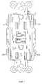
- FIG. 1is a three-dimensional exploded view of the circuit interrupting device of the present invention.
- FIG. 2is a perspective view of the circuit interrupting device of an embodiment of the present invention.
- FIG. 3is a perspective view of the circuit interrupting device of an embodiment of the present invention without the upper cover.
- FIG. 4is a view of the components on the electric circuit board placed inside the base of the circuit interrupting device of an embodiment of the present invention.
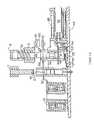
- FIG. 5Ais a sectional view of FIG. 3 following line A—A, schematically showing an interruption of the electric connection between the electric input end and the electric output end in the circuit interrupting device of an embodiment of the present invention.
- FIG. 5Bis a sectional view of FIG. 3 following line B—B, schematically showing an interruption of the electric connection between the electric input end and the electric output end in the circuit interrupting device of an embodiment of the present invention.
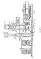
- FIG. 6Ais a sectional view of FIG. 3 following line A—A, schematically showing the electric connection between the electric input end and the electric output end in the circuit interrupting device of an embodiment of the present invention.
- FIG. 6Bis a sectional view of FIG. 3 following line B—B, schematically showing the electric connection between the electric input end and the electric output end in the circuit interrupting device of an embodiment of the present invention.
- FIG. 7Ais a sectional view of FIG. 3 following line A—A, schematically showing the interruption of the electric connection between the electric input end and the electric output end in the circuit interrupting device of an embodiment of the present invention.
- FIG. 7Bis a sectional view of FIG. 3 following line B—B, schematically showing the interruption of the electric connection between the electric input end and the electric output end in the circuit interrupting device of an embodiment of the present invention.
- FIG. 8is a schematic diagram of the electric circuit of the circuit interrupting device of an embodiment of the present invention.
- a circuit interrupting devicefor example a GFCI, an AFCI, or other device, according to an exemplary embodiment of the present invention mainly comprises an upper cover 2 , an intermediate support 3 , and a base 4 assembled together.
- an upper cover 2there are two electric output plugs 5 and 6 , a test button (TEST) 7 , and a reset button (RESET) 8 .
- TESTtest button
- RESETreset button
- a mounting strap 1is installed between the upper cover 2 and the intermediate support 3 .
- the mounting strap 1has ground points 11 , 12 that are connected to ground receptacles of the electric output plugs 5 , 6 through openings in the upper cover 2 .
- An electric circuit board 18is installed between the intermediate support 3 and the base 4 .
- the intermediate support 3includes a pair of output conductors 13 , 14 that are made from conductive materials.
- the output conductors 13 , 14are disposed on either side of the support 3 .
- the two output conductors 13 and 14have conductive members 60 , 61 , 62 , and 63 corresponding to the hot receptacles and white receptacles of the electric output plugs 5 , 6 in the upper cover 2 .
- the output conductors 13 , 14also comprise, respectively, electric contacts 15 and 16 .
- a test button switch piece 40is located between one of the output conductors 13 , 14 and the test button 7 .
- the base 4is used as a housing to enclose the intermediate support 3 and the electric circuit board 18 .
- Both sides of the base 4comprise, respectively, a pair of electric input connection screws 9 (HOT) and 10 (WHITE) and a pair of electric output connection screws 109 (HOT) and 110 (WHITE), coupled in parallel.
- HATelectric input connection screws 9
- WHITEelectric output connection screws 109
- WHITEelectric output connection screws 109
- WHITEelectric output connection screws
- the electric output leads 80 and 81have two electric contacts 52 and 53 , respectively.
- the electric circuit board 18comprises a pair of electrically conducting flexible input components 95 , 96 having four flexible input fingers 20 , 21 , 50 , and 51 , a differential transformer 19 for testing for leakage of electric current, a solenoid coil 26 having a plunger 42 therein, a reset button bias member 28 , and a flexible switch 37 .
- the flexible input fingers 20 , 21 , 50 and 51 at one end of the flexible input components 95 , 96have electric contacts 22 , 23 , 55 and 54 .
- the other ends of the flexible input components 95 , 96pass through the differential transformer 19 to connect via input leads 24 and 25 to the electric input connection screws 9 and 10 .
- the electric contacts 22 and 23 on the flexible input fingers 20 , 21correspond to the electric contacts 15 and 16 on the output conductors 13 , 14 in the intermediate support 3 .
- the electric contacts 54 and 55 on the flexible input fingers 50 , 51correspond to the electric contacts 52 and 53 on the electric output leads 80 and 81 in the base 4 .
- a solenoid coil 26is also included on the electric circuit board 18 , with a plunger 42 placed inside.
- a test resistor 27is located underneath the test button 7 on the upper cover 2 , with one end of the test resistor 27 connected to the input connection screw 10 (WHITE) (See FIG. 8 ).
- the reset button bias member 28 on the electric circuit board 18is located underneath the reset button 8 .
- a housing 100may be provided to support the reset button bias member (See FIG. 1 ).
- a portion of the bias member 28is arranged below the flexible input fingers 20 , 21 , 50 and 51 , as best seen in FIG. 5B .
- a central opening 29is provided in the top of the reset button bias member 28 , and a movable L-shaped latch 30 is arranged at the bottom of the reset button bias member 28 .
- the latch component 30includes an opening 31 .
- the latch 30has a first leg that extends into bias member 28 and through the central opening 29 .
- the latch 30is preferably movable in a horizontal direction through the bias member 28 .
- a second leg of the latch 30is disposed along side of the bias member 28 .
- a circular groove 33is provided between one side of the reset button bias member 28 and the second leg of the latch 30 .
- the circular groove 33has a spring 34 fit therein.
- the spring 34is biased against the second leg of the latch 30 .
- a directional lock 35is located inside the reset button bias member 28 and vertically passes through the central opening 29 .
- the directional lock 35has a bottom surface 41 .
- a locking groove 36is provided on the directional lock 35 , near the bottom surface 41 .
- a spring 91is provided to the top of the directional lock 35 , beneath the reset button 8 .
- the flexible switch 37is located between the reset button bias member 28 and the electric circuit board 18 .
- a first end of the flexible switch 37is connected to the electric circuit board 18 .
- a second end of the flexible switch 37is moveable and has a protruding pinpoint contact 39 that corresponds to a contact 38 disposed on the circuit board 18 underneath contact 39 .
- the first end of the flexible switch 37is connected to a rectifier circuit 120 , and the second end of the flexible switch is connected to a gate trigger 121 of a SCR (See FIG. 8 ).
- the flexible switch 37 and the SCRare used to test for and to guard against reverse wiring, i.e. to prevent an error in connecting the electric input wiring and the electric output wiring of the circuit interrupting device, as is described in more detail below.
- FIGS. 5A–6Bindicate an example of a scheme under which the circuit interrupting device of an exemplary embodiment of the present invention works to prevent leakage of electric current and to interrupt an electric connection between the input and the output.
- FIGS. 5A and 5Billustrate an exemplary circuit interrupting device with the circuit interrupted, that is, there in no connection between contacts 15 , 16 , 52 , 53 and contacts 20 , 21 , 50 , 51 , respectively.
- the reset button 8is depressed to reset the circuit interrupting device to a conducting state.
- the directional lock 35moves downward. As can be seen in FIG.
- the opening 31 in latch 30is misaligned, that is, offset, with the bottom surface 41 of the directional lock 35 .
- the bottom surface 41cannot pass through the opening 31 and is pressed against the surface of the latch 30 .
- the downward action of the directional lock 35 against the latch 30causes the bias member 28 to move downward. Because of the downward movement of the reset button bias member 28 , the pinpoint contact 39 on the flexible switch 37 is moved downward and connected to contact 38 as shown in FIGS. 5A and 5B .
- the flexible switch 37is connected at one end to resistor 27 , which in turn is connected to an anode 120 of a rectifier circuit.
- the other end of the flexible switch 37is connected through the contact 38 to a trigger gate 121 of the SCR.
- An electric connection between contacts 38 and 39completes a circuit between gate 121 and anode 120 .
- a positive voltageis provided at anode 120 .
- This voltageshould bias the SCR into a conducting state, allowing current to flow through the solenoid coil 26 .
- the solenoid coil 26is thus charged with electricity and yields a magnetic field, which draws the plunger 42 inward to hit on the latch 30 .
- the latch 30moves with the plunger 42 against the force of spring 34 , to the left in FIG. 5A .
- the movement of latch 30aligns the opening 31 with the bottom surface 41 of the directional lock 35 such that the bottom surface 41 of the directional lock 35 passes through the opening 31 , as shown in FIGS. 6A and 6B .
- FIGS. 6A and 6Billustrate the state of the circuit interrupting device after the reset button 8 is released.
- the pinpoint contact 39 and the contact 38 of the flexible switch 37are disconnected.
- a voltageis no longer present at gate 121 and the SCR is no longer biased into a conducting state.
- the electric currentno longer flows through solenoid coil 26 and the solenoid coil 26 no longer produces the magnetic field.
- the plunger 42no longer acts on the latch 30 .
- the spring 34 between the latch 30 and the reset button bias member 28causes the latch 30 to move back towards its misaligned position, to the right in FIGS. 5A and 6A .
- the directional lock 35is now positioned in opening 31 , the latch 30 cannot move completely back to the misaligned position. Instead, the opening 31 of the latch 30 slides into the locking groove 36 of the directional lock 35 . Due to the force of spring 34 , the directional lock 35 and the latch 30 are engaged with each other as shown in FIG. 6A .
- the release of the reset button 8allows the spring 91 near the top of the directional lock 35 to move the reset button 8 and the directional lock 35 upward. Due to the engagement of the directional lock 35 with the latch 30 , via the locking groove 36 and opening 31 as described above, the reset button bias member 28 also moves upward. The bias member 28 , in turn, lifts the contacts 22 , 23 , 55 , and 54 on the flexible input fingers 20 , 21 , 50 , and 51 upward to connect to the contacts 15 and 16 of the output conductors 13 , 14 and to the contacts 52 and 53 of the electric output leads 80 and 81 , so that the input and output are electrically connected ( FIGS. 6A and 6B ).
- FIGS. 5A , 5 B, and 8also illustrate an exemplary scheme of protection to interrupt the electric connection of the electric input and the electric output on the circuit interrupting device of an exemplary embodiment the present invention when the electric input is mistakenly reverse-wired to the electric output on the circuit interrupting device.
- the circuit interrupting deviceis reverse-wired, the pair of electric input wires are connected to the electric output screws 109 , 110 and the electric output wires are connected to the electric input screws 9 , 10 .
- FIG. 8although the circuit interrupting device itself is intact, when the reset button 8 is pressed down so that the two contacts 39 and 38 of the flexible switch 37 are connected, due to the reverse wiring, there is no electric voltage at the trigger gate of the SCR.
- the SCRis in a non-conducting state so that no electric current can pass through the solenoid coil 26 .
- the plunger 42does not move inward into the solenoid 26 and does not hit on the latch component 30 .
- the opening 31 in latch 30remains misaligned with the bottom surface 41 of the directional lock 35 .
- the directional lock 35cannot pass through opening 31 and the bottom surface 41 of the directional lock 35 stays pressed against the surface the latch component 30 .
- FIGS. 7A , 7 B and 8also illustrate the state of an exemplary circuit interrupting device when a fault has been detected.
- the circuit interrupting deviceis in the position illustrated in FIGS. 6A and 6B , with the contacts closed.
- the differential transformer 19 of the circuit interrupting device of an exemplary embodiment the present inventiondetects a leakage electric current
- a signalis provided to the IC ( FIG. 8 ).
- the ICgenerates a signal that biases the SCR into conducting state so that the solenoid coil 26 has electric current flowing therein, which produces a magnetic field.
- the plunger 42is drawn into the solenoid coil 26 by the magnetic field and hits on the latch 30 , which pushes the latch 30 against the force of spring 34 .
- the latch 30is thus moved to its aligned position.
- the locking groove 36 on the directional lock 35slides out of engagement with the opening 31 of the latch 30 .
- the directional lock 35is now free to move through opening 31 .
- the reset button 8moves up due to the force of the spring 91 and pulls the directional lock 35 upwards.
- the reset button bias member 28slides downward when pushed by flexible input fingers 20 , 21 , 50 , and 51 .
- the contacts 22 , 23 , 55 , 54 of the flexible input fingers 20 , 21 , 50 , and 51separate from the contacts 15 and 16 of the output conductors 13 and 14 and the contacts 52 and 53 of the electric output leads 80 and 81 .
- the electric connection between the electric input and the electric outputis interrupted, as shown in FIGS. 7A and 7B .
- test button 7When the user wants to disconnect the electric connection between the electric input and the electric output of the circuit interrupting device, the test button 7 is depressed so that the test button switch 40 is connected to the test resistor 27 .
- the differential transformer 19detects a test leakage electric current, the SCR becomes conducting. Consequently, the solenoid coil 26 has electric current flowing therein, which produces a magnetic field.
- the magnetic fielddraws the plunger 42 inward so that it hits on the latch 30 , which pushes the latch 30 against the force of spring 34 .
- the latch 30is thus moved to the aligned position.
- the locking groove 36 on the directional lock 35thus slides out of the opening 31 of the latch component 30 , see FIG. 7A .
- the reset button 8moves upward because of the force of spring 91 at the top of the directional lock 35 and the reset button bias member 28 moves downward due to the flexible input fingers 20 , 21 , 50 , and 51 .
- the contacts 22 , 23 , 55 , and 54 on the flexible input fingers 20 , 21 , 50 , and 51are disconnected from the contacts 15 and 16 of the output conductors 13 and 14 and the contacts 52 and 53 on the electric output leads 80 and 81 .
- the electric connection between the electric input and the electric outputis interrupted.
Landscapes
- Details Of Connecting Devices For Male And Female Coupling (AREA)
- Breakers (AREA)
Abstract
Description
Claims (17)
Priority Applications (1)
| Application Number | Priority Date | Filing Date | Title |
|---|---|---|---|
| CA2458791ACA2458791C (en) | 2003-02-20 | 2004-02-16 | Receptacle device having circuit interrupting and reverse wiring protection |
Applications Claiming Priority (2)
| Application Number | Priority Date | Filing Date | Title |
|---|---|---|---|
| CN02243497UCN2560125Y (en) | 2002-08-07 | 2002-08-07 | Leakage protection socket |
| CN02243497.6 | 2002-08-07 |
Publications (2)
| Publication Number | Publication Date |
|---|---|
| US20040027740A1 US20040027740A1 (en) | 2004-02-12 |
| US7019952B2true US7019952B2 (en) | 2006-03-28 |
Family
ID=4782725
Family Applications (1)
| Application Number | Title | Priority Date | Filing Date |
|---|---|---|---|
| US10/368,429Expired - Fee RelatedUS7019952B2 (en) | 2002-08-07 | 2003-02-20 | Receptacle device having circuit interrupting and reverse wiring protection |
Country Status (2)
| Country | Link |
|---|---|
| US (1) | US7019952B2 (en) |
| CN (1) | CN2560125Y (en) |
Cited By (42)
| Publication number | Priority date | Publication date | Assignee | Title |
|---|---|---|---|---|
| US20040223272A1 (en)* | 2003-02-03 | 2004-11-11 | Frantz Germain | Circuit interrupting device and system utilizing bridge contact mechanism and reset lockout |
| US20050105228A1 (en)* | 2003-11-18 | 2005-05-19 | Cheon-Youn Kim | Receptacle |
| US20060193092A1 (en)* | 2005-02-25 | 2006-08-31 | Shanghai Meihao Electric Inc | Ground fault circuit interrupter with end of life indicators |
| US20060238933A1 (en)* | 2005-02-25 | 2006-10-26 | Shanghai Meihao Electric Inc. | Ground fault circuit interrupters providing end of the life test |
| US20060274463A1 (en)* | 2005-02-25 | 2006-12-07 | Huadao Huang | Circuit interrupting device with automatic end of life test |
| US20060273859A1 (en)* | 2000-10-16 | 2006-12-07 | Frantz Germain | Reset lockout for sliding latch GFCI |
| US20060279886A1 (en)* | 2005-02-25 | 2006-12-14 | Shanghai Meihao Electric Inc. | Ground fault circuit interrupters with miswiring or reverse wiring protection and end of life alarm signal |
| US7154718B1 (en) | 2004-07-28 | 2006-12-26 | Pass & Seymour, Inc. | Protection device with power to receptacle cut-off |
| US20070014068A1 (en)* | 2005-02-25 | 2007-01-18 | Huadao Huang | Circuits for circuit interrupting devices having automatic end of life testing function |
| US7173799B1 (en) | 2004-02-03 | 2007-02-06 | Pass & Seymour, Inc. | Protection device with a sandwiched cantilever breaker mechanism |
| US20070049077A1 (en)* | 2005-08-31 | 2007-03-01 | Frantz Germain | Electrical wiring devices with a protective shutter |
| US20070076337A1 (en)* | 2005-02-25 | 2007-04-05 | Huadao Huang | Ground fault circuit interrupter containing a dual-function test button |
| US20070086127A1 (en)* | 2005-02-25 | 2007-04-19 | Huadao Huang | Ground fault circuit interrupter containing a dual-function test button |
| US20080170341A1 (en)* | 2007-01-17 | 2008-07-17 | Huadao Huang | Novel circuit interrupting device with automatic end-of-life test |
| US7411766B1 (en) | 2007-02-14 | 2008-08-12 | Huadao Huang | Circuit interrupting device with end of life testing functions |
| US20090086390A1 (en)* | 2007-09-30 | 2009-04-02 | Huadao Huang | Novel circuit interrupting device with high voltage surge protection |
| US20090086389A1 (en)* | 2007-09-30 | 2009-04-02 | Huadao Huang | Circuit interrupting device with end-of life testing, reverse wiring and high voltage surge capability |
| US20090091869A1 (en)* | 2007-07-10 | 2009-04-09 | Huadao Huang | Circuit interrupting device with automatic components detection function |
| US7538993B2 (en) | 2005-02-25 | 2009-05-26 | Huadao Huang | Receptacle circuit interrupting devices providing an end of life test controlled by test button |
| US20090161271A1 (en)* | 2007-09-30 | 2009-06-25 | Huadao Huang | Novel circuit interrupting device with interconnecting reset and test buttons |
| US7598828B1 (en) | 2004-07-28 | 2009-10-06 | Pass & Seymour, Inc. | Protection device with a sandwiched cantilever breaker mechanism |
| US20090262470A1 (en)* | 2002-05-09 | 2009-10-22 | Nelson Bonilla | GFCI that cannot be reset until wired correctly on line side and power is applied |
| US20100073178A1 (en)* | 2007-09-30 | 2010-03-25 | Huadao Huang | Novel circuit interrupting device with high voltage surge protection |
| US20100217546A1 (en)* | 2009-02-20 | 2010-08-26 | Anthony Locker | Methods and Apparatuses for Detecting Faults in Electrical Power Systems |
| US7833030B1 (en)* | 2009-07-29 | 2010-11-16 | Huadao Huang | Safety shield for electrical receptacles |
| US7907371B2 (en) | 1998-08-24 | 2011-03-15 | Leviton Manufacturing Company, Inc. | Circuit interrupting device with reset lockout and reverse wiring protection and method of manufacture |
| US20110115511A1 (en)* | 2000-02-17 | 2011-05-19 | Pass & Seymour, Inc. | Electrical device with miswire protection and automated testing |
| US20110149453A1 (en)* | 2008-07-07 | 2011-06-23 | Leviton Manufacturing Company, Inc. | Fault circuit interrupter device |
| US20120083142A1 (en)* | 2010-09-30 | 2012-04-05 | Huadao Huang | Power Outlet with Shield Locking Mechanism |
| US8297990B2 (en)* | 2010-09-30 | 2012-10-30 | Huadao Huang | Leakage protection outlet |
| US20120287537A1 (en)* | 2011-05-11 | 2012-11-15 | Huadao Huang | Leakage detection protection circuit |
| US8437108B1 (en)* | 2004-07-28 | 2013-05-07 | Pass & Seymour, Inc. | Protective device with separate end-of-life trip mechanism |
| US8444309B2 (en) | 2010-08-13 | 2013-05-21 | Leviton Manufacturing Company, Inc. | Wiring device with illumination |
| US20130171847A1 (en)* | 2010-09-30 | 2013-07-04 | Huadao Huang | Leakage protection socket with integrated baffle locking mechanism |
| US20130241678A1 (en)* | 2012-03-16 | 2013-09-19 | Gaetano Bonasia | Reinstallable Circuit Interrupting Device with Vibration Resistant Miswire Protection |
| US8550829B2 (en) | 2010-09-30 | 2013-10-08 | Huadao Huang | Power outlet with jack safety shield device |
| US8830015B2 (en) | 2012-03-16 | 2014-09-09 | Hubbell Incorporated | Compact latching mechanism for switched electrical device |
| US9048559B2 (en) | 2011-05-12 | 2015-06-02 | Huadao Huang | Power outlet with jack safety shield device |
| US9362077B2 (en) | 2000-02-17 | 2016-06-07 | Pass & Seymour, Inc. | Electrical device with miswire protection and automated testing |
| US9551751B2 (en) | 2011-06-15 | 2017-01-24 | Ul Llc | High speed controllable load |
| US9774181B2 (en) | 2012-03-16 | 2017-09-26 | Hubbell Incorporated | Enhanced auto-monitoring circuit and method for an electrical device |
| US10317431B2 (en) | 2016-10-07 | 2019-06-11 | Leviton Manufacturing Co., Inc. | Multiple core transformer assembly |
Families Citing this family (16)
| Publication number | Priority date | Publication date | Assignee | Title |
|---|---|---|---|---|
| CN2914318Y (en)* | 2006-05-30 | 2007-06-20 | 上海益而益电器制造有限公司 | Enhanced ground-fault circuit breaker with reverse connection protecting function |
| CN101162814B (en)* | 2006-10-13 | 2011-09-07 | 黄华道 | Creepage protecting socket |
| CN200993948Y (en)* | 2006-11-14 | 2007-12-19 | 上海益而益电器制造有限公司 | Safety earth fault circuit breaker |
| CN101453113B (en)* | 2007-12-07 | 2011-02-09 | 上海益而益电器制造有限公司 | Grounding fault breaking apparatus having circuit status detection function |
| CN201181681Y (en)* | 2008-04-14 | 2009-01-14 | 上海益而益电器制造有限公司 | Trip mechanism and creepage protecting socket with the same |
| CN101645566B (en)* | 2008-08-07 | 2013-07-24 | 林雪莲 | Leakage protection socket |
| CN101867181A (en)* | 2009-04-16 | 2010-10-20 | 上海益而益电器制造有限公司 | Wiring protection device |
| DE102009025513A1 (en)* | 2009-06-19 | 2010-12-30 | Ellenberger & Poensgen Gmbh | Electronic circuit breaker |
| US9531287B1 (en)* | 2011-11-28 | 2016-12-27 | John Michael Johnson | Recreational vehicle transformer |
| CN104836189B (en)* | 2015-04-14 | 2018-01-26 | 华南理工大学建筑设计研究院 | It is a kind of can Self-resetting and remote reset electric protective device and its method |
| US10170265B2 (en)* | 2016-12-14 | 2019-01-01 | Chengli Li | Leakage current protection device |
| US10770844B2 (en) | 2016-12-14 | 2020-09-08 | Chengli Li | Leakage current protection device for power plug |
| US10644438B2 (en) | 2017-05-11 | 2020-05-05 | Chengli Li | Power plug with leakage current protection device |
| CN111029226B (en)* | 2019-12-07 | 2020-11-06 | 浙江大学 | An anti-vandal charge control circuit breaker control system and charge control circuit breaker |
| CN111342307B (en)* | 2020-03-16 | 2021-08-10 | 南京金升华包装材料有限公司 | Intelligent wall socket capable of preventing reverse connection of power lines |
| CN112688132A (en)* | 2020-12-11 | 2021-04-20 | 马云飞 | Anti-creeping mechanism with strong protection and capable of rapidly cutting off power |
Citations (9)
| Publication number | Priority date | Publication date | Assignee | Title |
|---|---|---|---|---|
| US4595894A (en) | 1983-12-05 | 1986-06-17 | Leviton Manufacturing Co., Inc. | Ground fault circuit interrupting system |
| US5963408A (en) | 1993-07-08 | 1999-10-05 | Leviton Manufacturing Co., Inc. | Ground fault circuit interrupter incorporating miswiring prevention circuitry |
| US6040967A (en) | 1998-08-24 | 2000-03-21 | Leviton Manufacturing Co., Inc. | Reset lockout for circuit interrupting device |
| US6246558B1 (en) | 1998-08-24 | 2001-06-12 | Leviton Manufacturing Company | Circuit interrupting device with reverse wiring protection |
| US6252407B1 (en) | 1996-12-18 | 2001-06-26 | Leviton Manufacturing Co., Inc. | Ground fault circuit interrupter miswiring prevention device |
| US6262871B1 (en)* | 1998-05-28 | 2001-07-17 | X-L Synergy, Llc | Fail safe fault interrupter |
| US6282070B1 (en) | 1998-08-24 | 2001-08-28 | Leviton Manufacturing Co., Inc. | Circuit interrupting system with independent trip and reset lockout |
| US6580344B2 (en)* | 2000-09-04 | 2003-06-17 | Huadao Huang | Ground fault interruption receptacle |
| US6671145B2 (en)* | 2001-03-20 | 2003-12-30 | Leviton Manufacturing Co., Inc. | Reset lockout mechanism and independent trip mechanism for center latch circuit interrupting device |
- 2002
- 2002-08-07CNCN02243497Upatent/CN2560125Y/ennot_activeExpired - Fee Related
- 2003
- 2003-02-20USUS10/368,429patent/US7019952B2/ennot_activeExpired - Fee Related
Patent Citations (10)
| Publication number | Priority date | Publication date | Assignee | Title |
|---|---|---|---|---|
| US4595894A (en) | 1983-12-05 | 1986-06-17 | Leviton Manufacturing Co., Inc. | Ground fault circuit interrupting system |
| US5963408A (en) | 1993-07-08 | 1999-10-05 | Leviton Manufacturing Co., Inc. | Ground fault circuit interrupter incorporating miswiring prevention circuitry |
| US6252407B1 (en) | 1996-12-18 | 2001-06-26 | Leviton Manufacturing Co., Inc. | Ground fault circuit interrupter miswiring prevention device |
| US6262871B1 (en)* | 1998-05-28 | 2001-07-17 | X-L Synergy, Llc | Fail safe fault interrupter |
| US6040967A (en) | 1998-08-24 | 2000-03-21 | Leviton Manufacturing Co., Inc. | Reset lockout for circuit interrupting device |
| US6246558B1 (en) | 1998-08-24 | 2001-06-12 | Leviton Manufacturing Company | Circuit interrupting device with reverse wiring protection |
| US6282070B1 (en) | 1998-08-24 | 2001-08-28 | Leviton Manufacturing Co., Inc. | Circuit interrupting system with independent trip and reset lockout |
| US6381112B1 (en) | 1998-08-24 | 2002-04-30 | Leviton Manufacturing Co., Inc. | Reset lockout for circuit interrupting device |
| US6580344B2 (en)* | 2000-09-04 | 2003-06-17 | Huadao Huang | Ground fault interruption receptacle |
| US6671145B2 (en)* | 2001-03-20 | 2003-12-30 | Leviton Manufacturing Co., Inc. | Reset lockout mechanism and independent trip mechanism for center latch circuit interrupting device |
Cited By (85)
| Publication number | Priority date | Publication date | Assignee | Title |
|---|---|---|---|---|
| US7907371B2 (en) | 1998-08-24 | 2011-03-15 | Leviton Manufacturing Company, Inc. | Circuit interrupting device with reset lockout and reverse wiring protection and method of manufacture |
| US8054595B2 (en) | 1998-08-24 | 2011-11-08 | Leviton Manufacturing Co., Inc. | Circuit interrupting device with reset lockout |
| US8130480B2 (en) | 1998-08-24 | 2012-03-06 | Leviton Manufactuing Co., Inc. | Circuit interrupting device with reset lockout |
| US9362077B2 (en) | 2000-02-17 | 2016-06-07 | Pass & Seymour, Inc. | Electrical device with miswire protection and automated testing |
| US20110115511A1 (en)* | 2000-02-17 | 2011-05-19 | Pass & Seymour, Inc. | Electrical device with miswire protection and automated testing |
| US8299799B2 (en) | 2000-02-17 | 2012-10-30 | Pass & Seymour, Inc. | Electrical device with miswire protection and automated testing |
| US8004804B2 (en) | 2000-10-16 | 2011-08-23 | Leviton Manufacturing Co., Inc. | Circuit interrupter having at least one indicator |
| US20060273859A1 (en)* | 2000-10-16 | 2006-12-07 | Frantz Germain | Reset lockout for sliding latch GFCI |
| US20100039278A1 (en)* | 2000-10-16 | 2010-02-18 | Leviton Manfucturing Co., Inc. | Reset lockout for sliding latch gfci |
| US7492558B2 (en) | 2000-10-16 | 2009-02-17 | Leviton Manufacturing Co., Inc. | Reset lockout for sliding latch GFCI |
| US20090262470A1 (en)* | 2002-05-09 | 2009-10-22 | Nelson Bonilla | GFCI that cannot be reset until wired correctly on line side and power is applied |
| US20110102953A1 (en)* | 2002-05-09 | 2011-05-05 | Nelson Bonilla | GFCI that cannot be reset until wired correctly on line side and power is applied |
| US7889465B2 (en) | 2002-05-09 | 2011-02-15 | Hubbell Incorporated | GFCI that cannot be reset until wired correctly on line side and power is applied |
| US8089738B2 (en) | 2002-05-09 | 2012-01-03 | Hubbell Incorporated | GFCI that cannot be reset until wired correctly on line side and power is applied |
| US7737809B2 (en) | 2003-02-03 | 2010-06-15 | Leviton Manufacturing Co., Inc. | Circuit interrupting device and system utilizing bridge contact mechanism and reset lockout |
| US20040223272A1 (en)* | 2003-02-03 | 2004-11-11 | Frantz Germain | Circuit interrupting device and system utilizing bridge contact mechanism and reset lockout |
| US9118172B2 (en)* | 2003-10-17 | 2015-08-25 | Pass & Seymour, Inc. | Protective device with automated self test |
| US20130293990A1 (en)* | 2003-10-17 | 2013-11-07 | Pass & Seymour, Inc. | Protective device with automated self test |
| US20050105228A1 (en)* | 2003-11-18 | 2005-05-19 | Cheon-Youn Kim | Receptacle |
| US8102226B2 (en) | 2004-02-03 | 2012-01-24 | Pass And Seymour, Inc. | Protection device with a sandwiched cantilever breaker mechanism |
| US8446234B2 (en) | 2004-02-03 | 2013-05-21 | Pass & Seymour, Inc. | Protection device with a sandwiched cantilever breaker mechanism |
| US7936238B1 (en) | 2004-02-03 | 2011-05-03 | Pass & Seymour, Inc. | Protection device with a sandwiched cantilever breaker mechanism |
| US7173799B1 (en) | 2004-02-03 | 2007-02-06 | Pass & Seymour, Inc. | Protection device with a sandwiched cantilever breaker mechanism |
| US9007153B2 (en) | 2004-02-03 | 2015-04-14 | Pass & Seymour, Inc. | Protection device with a sandwiched cantilever breaker mechanism |
| US7154718B1 (en) | 2004-07-28 | 2006-12-26 | Pass & Seymour, Inc. | Protection device with power to receptacle cut-off |
| US7598828B1 (en) | 2004-07-28 | 2009-10-06 | Pass & Seymour, Inc. | Protection device with a sandwiched cantilever breaker mechanism |
| US8477466B1 (en)* | 2004-07-28 | 2013-07-02 | Pass & Seymour, Inc. | Protective device with separate end-of-life trip mechanism |
| US8437108B1 (en)* | 2004-07-28 | 2013-05-07 | Pass & Seymour, Inc. | Protective device with separate end-of-life trip mechanism |
| US20060274463A1 (en)* | 2005-02-25 | 2006-12-07 | Huadao Huang | Circuit interrupting device with automatic end of life test |
| US7195500B2 (en) | 2005-02-25 | 2007-03-27 | Huadao Huang | Ground fault circuit interrupter with end of life indicators |
| US7315227B2 (en) | 2005-02-25 | 2008-01-01 | Huadao Huang | Ground fault circuit interrupters providing end of the life test |
| US7633726B2 (en) | 2005-02-25 | 2009-12-15 | Huadao Huang | Ground fault circuit interrupters with miswiring or reverse wiring protection and end of life alarm signal |
| US20060279886A1 (en)* | 2005-02-25 | 2006-12-14 | Shanghai Meihao Electric Inc. | Ground fault circuit interrupters with miswiring or reverse wiring protection and end of life alarm signal |
| US7538993B2 (en) | 2005-02-25 | 2009-05-26 | Huadao Huang | Receptacle circuit interrupting devices providing an end of life test controlled by test button |
| US7295415B2 (en) | 2005-02-25 | 2007-11-13 | Huadao Huang | Circuits for circuit interrupting devices having automatic end of life testing function |
| US20070014068A1 (en)* | 2005-02-25 | 2007-01-18 | Huadao Huang | Circuits for circuit interrupting devices having automatic end of life testing function |
| US7289306B2 (en) | 2005-02-25 | 2007-10-30 | Huadao Huang | Ground fault circuit interrupter containing a dual-function test button |
| US20060238933A1 (en)* | 2005-02-25 | 2006-10-26 | Shanghai Meihao Electric Inc. | Ground fault circuit interrupters providing end of the life test |
| US20060193092A1 (en)* | 2005-02-25 | 2006-08-31 | Shanghai Meihao Electric Inc | Ground fault circuit interrupter with end of life indicators |
| US7265956B2 (en) | 2005-02-25 | 2007-09-04 | Huadao Huang | Ground fault circuit interrupter containing a dual-function test button |
| US20070086127A1 (en)* | 2005-02-25 | 2007-04-19 | Huadao Huang | Ground fault circuit interrupter containing a dual-function test button |
| US7317600B2 (en) | 2005-02-25 | 2008-01-08 | Huadao Huang | Circuit interrupting device with automatic end of life test |
| US20070076337A1 (en)* | 2005-02-25 | 2007-04-05 | Huadao Huang | Ground fault circuit interrupter containing a dual-function test button |
| US7455538B2 (en) | 2005-08-31 | 2008-11-25 | Leviton Manufacturing Co., Inc. | Electrical wiring devices with a protective shutter |
| US20070049077A1 (en)* | 2005-08-31 | 2007-03-01 | Frantz Germain | Electrical wiring devices with a protective shutter |
| US20080170341A1 (en)* | 2007-01-17 | 2008-07-17 | Huadao Huang | Novel circuit interrupting device with automatic end-of-life test |
| US7576959B2 (en) | 2007-01-17 | 2009-08-18 | Huadao Huang | Circuit interrupting device with automatic end-of-life test |
| US7411766B1 (en) | 2007-02-14 | 2008-08-12 | Huadao Huang | Circuit interrupting device with end of life testing functions |
| US7859368B2 (en) | 2007-07-10 | 2010-12-28 | Huadao Huang | Circuit interrupting device with automatic components detection function |
| US20090091869A1 (en)* | 2007-07-10 | 2009-04-09 | Huadao Huang | Circuit interrupting device with automatic components detection function |
| US20100073178A1 (en)* | 2007-09-30 | 2010-03-25 | Huadao Huang | Novel circuit interrupting device with high voltage surge protection |
| US8462471B2 (en) | 2007-09-30 | 2013-06-11 | Huadao Huang | Circuit interrupting device with high voltage surge protection |
| US8233251B2 (en) | 2007-09-30 | 2012-07-31 | Huadao Huang | Circuit interrupting device with interconnecting reset and test buttons |
| US20090086390A1 (en)* | 2007-09-30 | 2009-04-02 | Huadao Huang | Novel circuit interrupting device with high voltage surge protection |
| US20090086389A1 (en)* | 2007-09-30 | 2009-04-02 | Huadao Huang | Circuit interrupting device with end-of life testing, reverse wiring and high voltage surge capability |
| US8300368B2 (en)* | 2007-09-30 | 2012-10-30 | Huadao Huang | Circuit interrupting device with end-of life testing, reverse wiring and high voltage surge capability |
| US7940498B2 (en) | 2007-09-30 | 2011-05-10 | Huadao Huang | Circuit interrupting device with high voltage surge protection |
| US20090161271A1 (en)* | 2007-09-30 | 2009-06-25 | Huadao Huang | Novel circuit interrupting device with interconnecting reset and test buttons |
| US20110211283A1 (en)* | 2007-09-30 | 2011-09-01 | Huadao Huang | Novel circuit interrupting device with high voltage surge protection |
| US11456138B2 (en) | 2008-07-07 | 2022-09-27 | Leviton Manufacturing Co., Inc. | Fault circuit interrupter device |
| US20110149453A1 (en)* | 2008-07-07 | 2011-06-23 | Leviton Manufacturing Company, Inc. | Fault circuit interrupter device |
| US8587914B2 (en) | 2008-07-07 | 2013-11-19 | Leviton Manufacturing Co., Inc. | Fault circuit interrupter device |
| US20100217546A1 (en)* | 2009-02-20 | 2010-08-26 | Anthony Locker | Methods and Apparatuses for Detecting Faults in Electrical Power Systems |
| US20100213952A1 (en)* | 2009-02-20 | 2010-08-26 | Anthony Locker | Methods and Apparatuses for Determining Charging Current in Electrical Power Systems |
| US7833030B1 (en)* | 2009-07-29 | 2010-11-16 | Huadao Huang | Safety shield for electrical receptacles |
| US8444309B2 (en) | 2010-08-13 | 2013-05-21 | Leviton Manufacturing Company, Inc. | Wiring device with illumination |
| US8297990B2 (en)* | 2010-09-30 | 2012-10-30 | Huadao Huang | Leakage protection outlet |
| US8858245B2 (en)* | 2010-09-30 | 2014-10-14 | Huadao Huang | Leakage protection socket with integrated baffle locking mechanism |
| US20120083142A1 (en)* | 2010-09-30 | 2012-04-05 | Huadao Huang | Power Outlet with Shield Locking Mechanism |
| US8550829B2 (en) | 2010-09-30 | 2013-10-08 | Huadao Huang | Power outlet with jack safety shield device |
| US20130171847A1 (en)* | 2010-09-30 | 2013-07-04 | Huadao Huang | Leakage protection socket with integrated baffle locking mechanism |
| US8382497B2 (en)* | 2010-09-30 | 2013-02-26 | Huadao Huang | Power outlet with shield locking mechanism |
| US20120287537A1 (en)* | 2011-05-11 | 2012-11-15 | Huadao Huang | Leakage detection protection circuit |
| US9088152B2 (en)* | 2011-05-11 | 2015-07-21 | Huadao Huang | Leakage detection protection circuit |
| US9048559B2 (en) | 2011-05-12 | 2015-06-02 | Huadao Huang | Power outlet with jack safety shield device |
| US9869719B2 (en) | 2011-06-15 | 2018-01-16 | Ul Llc | High speed controllable load |
| US9551751B2 (en) | 2011-06-15 | 2017-01-24 | Ul Llc | High speed controllable load |
| US9147548B2 (en)* | 2012-03-16 | 2015-09-29 | Hubbell Incorporated | Reinstallable circuit interrupting device with vibration resistant miswire protection |
| US9774181B2 (en) | 2012-03-16 | 2017-09-26 | Hubbell Incorporated | Enhanced auto-monitoring circuit and method for an electrical device |
| US20130241678A1 (en)* | 2012-03-16 | 2013-09-19 | Gaetano Bonasia | Reinstallable Circuit Interrupting Device with Vibration Resistant Miswire Protection |
| US10236678B2 (en) | 2012-03-16 | 2019-03-19 | Hubbell Incorporated | Reinstallable circuit interrupting device with vibration resistant miswire protection |
| US10630066B2 (en) | 2012-03-16 | 2020-04-21 | Hubbell Incorporated | Enhanced auto-monitoring circuit and method for an electrical device |
| US8830015B2 (en) | 2012-03-16 | 2014-09-09 | Hubbell Incorporated | Compact latching mechanism for switched electrical device |
| US10317431B2 (en) | 2016-10-07 | 2019-06-11 | Leviton Manufacturing Co., Inc. | Multiple core transformer assembly |
| US10690700B2 (en) | 2016-10-07 | 2020-06-23 | Leviton Manufacturing Company, Inc. | Multiple core transformer assembly |
Also Published As
| Publication number | Publication date |
|---|---|
| US20040027740A1 (en) | 2004-02-12 |
| CN2560125Y (en) | 2003-07-09 |
Similar Documents
| Publication | Publication Date | Title |
|---|---|---|
| US7019952B2 (en) | Receptacle device having circuit interrupting and reverse wiring protection | |
| US7195500B2 (en) | Ground fault circuit interrupter with end of life indicators | |
| US7049911B2 (en) | Circuit interrupting device and system utilizing electromechanical reset | |
| US7737809B2 (en) | Circuit interrupting device and system utilizing bridge contact mechanism and reset lockout | |
| US7411766B1 (en) | Circuit interrupting device with end of life testing functions | |
| US7701680B2 (en) | Ground-fault circuit interrupter | |
| US7558034B2 (en) | Bi-directional ground fault circuit interrupter | |
| US7576959B2 (en) | Circuit interrupting device with automatic end-of-life test | |
| US7317600B2 (en) | Circuit interrupting device with automatic end of life test | |
| US7538993B2 (en) | Receptacle circuit interrupting devices providing an end of life test controlled by test button | |
| US8558646B2 (en) | Disconnect mechanism in a power receptacle with ground-fault circuit interruption functions | |
| US6946935B2 (en) | Ground fault circuit interrupter with reverse wiring protection | |
| US6788173B2 (en) | Reset lockout and trip for circuit interrupting device | |
| US7315227B2 (en) | Ground fault circuit interrupters providing end of the life test | |
| US9450395B2 (en) | Manual reset ground fault circuit interruptor (GFCI) with a quick connect load input | |
| US7414499B2 (en) | Circuit interrupting device with a single test-reset button | |
| US20070268635A1 (en) | Bi-directional ground fault circuit interrupter | |
| US20080094765A1 (en) | Circuit interrupting device with automatic end of life test | |
| US5563756A (en) | Resettable ground fault circuit interrupter | |
| CA2458791C (en) | Receptacle device having circuit interrupting and reverse wiring protection | |
| HK1089298B (en) | Circuit interrupting device with single throw, double mode button for test-reset function | |
| HK1089298A1 (en) | Circuit interrupting device with single throw, double mode button for test-reset function | |
| KR20040063618A (en) | Receptacle |
Legal Events
| Date | Code | Title | Description |
|---|---|---|---|
| AS | Assignment | Owner name:SHANGHAI MEIHAO EICTRIC INC., CHINA Free format text:ASSIGNMENT OF ASSIGNORS INTEREST;ASSIGNORS:HUANG, HUADAO;LI, CHENGLI;REEL/FRAME:013794/0729 Effective date:20030215 | |
| RF | Reissue application filed | Effective date:20080314 | |
| REMI | Maintenance fee reminder mailed | ||
| FEPP | Fee payment procedure | Free format text:PETITION RELATED TO MAINTENANCE FEES GRANTED (ORIGINAL EVENT CODE: PMFG); ENTITY STATUS OF PATENT OWNER: LARGE ENTITY Free format text:PAT HOLDER NO LONGER CLAIMS SMALL ENTITY STATUS, ENTITY STATUS SET TO UNDISCOUNTED (ORIGINAL EVENT CODE: STOL); ENTITY STATUS OF PATENT OWNER: LARGE ENTITY Free format text:PETITION RELATED TO MAINTENANCE FEES FILED (ORIGINAL EVENT CODE: PMFP); ENTITY STATUS OF PATENT OWNER: LARGE ENTITY | |
| REIN | Reinstatement after maintenance fee payment confirmed | ||
| PRDP | Patent reinstated due to the acceptance of a late maintenance fee | Effective date:20100518 | |
| FP | Lapsed due to failure to pay maintenance fee | Effective date:20100328 | |
| FPAY | Fee payment | Year of fee payment:4 | |
| SULP | Surcharge for late payment | ||
| REMI | Maintenance fee reminder mailed | ||
| FPAY | Fee payment | Year of fee payment:8 | |
| SULP | Surcharge for late payment | Year of fee payment:7 | |
| FEPP | Fee payment procedure | Free format text:MAINTENANCE FEE REMINDER MAILED (ORIGINAL EVENT CODE: REM.) | |
| LAPS | Lapse for failure to pay maintenance fees | Free format text:PATENT EXPIRED FOR FAILURE TO PAY MAINTENANCE FEES (ORIGINAL EVENT CODE: EXP.) | |
| STCH | Information on status: patent discontinuation | Free format text:PATENT EXPIRED DUE TO NONPAYMENT OF MAINTENANCE FEES UNDER 37 CFR 1.362 | |
| FP | Lapsed due to failure to pay maintenance fee | Effective date:20180328 |