US7019777B2 - Multispectral imaging system with spatial resolution enhancement - Google Patents
Multispectral imaging system with spatial resolution enhancementDownload PDFInfo
- Publication number
- US7019777B2 US7019777B2US09/838,712US83871201AUS7019777B2US 7019777 B2US7019777 B2US 7019777B2US 83871201 AUS83871201 AUS 83871201AUS 7019777 B2US7019777 B2US 7019777B2
- Authority
- US
- United States
- Prior art keywords
- images
- band
- multispectral
- cameras
- camis
- Prior art date
- Legal status (The legal status is an assumption and is not a legal conclusion. Google has not performed a legal analysis and makes no representation as to the accuracy of the status listed.)
- Expired - Fee Related, expires
Links
Images


Classifications
- H—ELECTRICITY
- H04—ELECTRIC COMMUNICATION TECHNIQUE
- H04N—PICTORIAL COMMUNICATION, e.g. TELEVISION
- H04N23/00—Cameras or camera modules comprising electronic image sensors; Control thereof
- H04N23/10—Cameras or camera modules comprising electronic image sensors; Control thereof for generating image signals from different wavelengths
- H04N23/11—Cameras or camera modules comprising electronic image sensors; Control thereof for generating image signals from different wavelengths for generating image signals from visible and infrared light wavelengths
- H—ELECTRICITY
- H04—ELECTRIC COMMUNICATION TECHNIQUE
- H04N—PICTORIAL COMMUNICATION, e.g. TELEVISION
- H04N25/00—Circuitry of solid-state image sensors [SSIS]; Control thereof
- H04N25/40—Extracting pixel data from image sensors by controlling scanning circuits, e.g. by modifying the number of pixels sampled or to be sampled
- H04N25/41—Extracting pixel data from a plurality of image sensors simultaneously picking up an image, e.g. for increasing the field of view by combining the outputs of a plurality of sensors
Definitions
- This inventionrelates to an airborne multispectral imaging system and in particular to a computerized airborne multicamera imaging system with spatial resolution enhancement and extended dynamic range.
- New generations of smaller, lighter, power saving, cheaper and better hyperspectral/multispectral imaging systemsare becoming operational to fly with diverse low-cost flying platforms in traditional light aircraft, balloons and airships to the latest unmanned aerial vehicles (UAVs).
- UAVsunmanned aerial vehicles
- Quickly available higher spatial and spectral resolution airborne spectral images with extended dynamic rangeare broadly desired for regional, special and satellite-demanded ground truth remote sensing applications.
- Modern hyperspectral, multispectral, and hyperspectral/multispectral multi-use airborne imaging systems for manned and unmanned aerial vehiclesare capable of acquiring hyperspectral pushbroom scanning images, multiangle-multispectral pushbroom scanning images, and/or multispectral photographic framing images to satisfy a wide variety of remote sensing applications.
- Almost all these systemsfeature some sort of computerization, which not only permits bursting the acquired spectral images into computer memory for real-time analysis and saving them directly into the computer hard disk but also enables intelligent system control and automation.
- Spatial resolutionis one of the most demanding factors for remote sensing applications. Spatial resolution describes the fineness of detail that can be distinguished in an image. Higher resolution allows us to distinguish smaller objects. As the resolution linearly increases, amount of (or the market) for remote sensing applications could exponentially increase. For example, one-meter resolution satellite and airborne images can easily recognize cars and school buses, and can be used for road and pavement management, disaster relief control and many other city or regional plans. Sub-foot to inch-resolution airborne multispectral images, demonstrated in the system described herein, are desirable for many advanced innovative applications. From moose and wetland bird counting for wildlife management to under-canopy forestland monitoring, from village and golf course precision survey to town and country precision mapping, the applications are endless.
- Dynamic rangeis another demanding aspect for remote sensing applications.
- the dynamic rangeis defined as the ratio of maximum measurable signal to minimum detectable signal.
- remote sensingit is the ability to discover dim features in the presence of strong, bright objects.
- Remote sensingproduces wide area coverage and vast quantities of collected data. Very often the areas of interest include diverse dim and bright objects. Examples include searching for a downed light aircraft hidden in the forest or shallow water, monitoring the results of human controlled bush burning under a forest canopy, and evidence of illegal logging, where the faint and dim objects situated in the dark shadow areas of forest canopy are required to be detectable in the presence of very bright, very well illuminated canopies.
- VFISvariable interference filter imaging spectrometer
- C 2 VIFISvariable interference imaging spectrometer
- Spectrally filtered video datais obtained from three synchronized CCD-imager modules or cameras wherein one imager module has a visible range variable interference filter on its surface, a second imager module has a near-infrared variable interference filter on its surface, and a third imager module has a bandpass filter attached to the imager.
- An alternating staring/scanning methodis used to optimize a pushbroom hyperspectral image data set with a photogrammetric reference.
- a computerized airborne multicamera imaging system(CAMIS) is described in a paper by Xiuhong Sun, James Baker and Richard Hordon entitled “Computerized Airborne Multicamera Imaging System” (CAMIS), Second International Airborne Remote Sensing Conference and Exhibition, San Francisco, Calif., 22-27 Jun. 1996.
- the CAMIScomprises a personal computer such as a Pentium 133 MHz computer which receives data from three synchronized CCD cameras with interchangeable narrow-band interference filters and a variable interference filter. Simultaneous, digital multichannel images are directly recorded onto SCSI drives without compression.
- CAMIScomputerized airborne multicamera imaging system
- This improved CAMISis a direct-sensor-to-computer imaging system which has integrated real-time positioning, a live moving map, and a live composite image display window for four cameras into a compact personal computer running under Windows NT.
- This paperalso shows that a sequence of four channel CAMIS snapshots can be composed and mosaiked as a natural/NIR color composite pair with larger coverage, in which spectral characteristics beyond human eyes become easily recognized because of the large scale aerial multispectral viewing.
- the present inventionis a further improvement of the CAMIS having not only four synchronized progressive scan CCD video cameras with interchangeable narrow band interference filters but also spatial resolution enhancement and extended dynamic range.
- CAMIScomputerized airborne multicamera imaging system
- an imaging system having spatial resolution enhancementcomprising means for providing multispectral bands of images, a computer connected to the means for providing the multispectral bands of images for receiving the multispectral bands of images, means within the computer for resampling-up the multispectral bands of spectral, means for storing the resampled-up multispectral bands of images; and means for performing multispectral band-to-band pixel registration of the resampled-up images.
- the computercomprises a memory for storing the resampled-up, registered images.
- the means for producing multispectral bands of imagescomprises a plurality of cameras.
- the plurality of camerascomprises an interline transfer, black and white, progressive scan, CCD video cameras.
- Each of the plurality of camerascomprises 782 ⁇ 576 square pixels.
- the plurality of camerasare optically aligned with a fractional pixel offset to each other.
- Each of the plurality of camerascomprises a narrow band interference filter in front of the lens of each of the plurality of cameras.
- the narrow band interference filter in front of each of the plurality of camerascomprises user selectable spectral bands within a spectral range covering blue, green, red and near infrared.
- the means for resampling-up the multispectral bands of imagescomprises a routine for performing a neighbor average interpolation.
- the computercomprises means for acquiring a bracket of computer controlled multiple exposures of the multispectral bands of images for extending dynamic range.
- a method of providing an imaging system with spatial resolution enhancementcomprising the steps of providing a sensor head including a plurality of cameras, each of the cameras having a narrow band interference filter producing multispectral bands of images, digitizing the multispectral bands of images from the plurality of cameras, storing the digitized multispectral bands of images, performing a resampling-up operation on the bands of images, and performing band-to-band pixel registrations of the bands of images.
- the methodcomprises the step of storing the resampled-up, registered images in a memory.
- the methodcomprises the step of the cameras being optically aligned with a fractional pixel offset to each other.
- the step of performing the resampling-up operation on the bands of imagescomprises the step of performing a neighbor average interpolation.
- the step of providing a sensor head including a plurality of camerascomprises the step of providing progressive scan, interline transfer, CCD video cameras.
- the step of providing a sensor head including a plurality of cameras each of the cameras having a narrow band interference filtercomprises the step of the narrow band interference filter having user selectable spectral bands within a spectral range covering blue, green, red and near infrared.
- the step of providing a sensor head including a plurality of camerascomprises the step of providing each of the plurality of cameras with 782 ⁇ 576 square pixels.
- the step of performing band-to-band pixel registration of the multiband imagescomprises the step of cropping edges of the multiband composite to produce a 1532 ⁇ 1150 ⁇ 4 bands formatted image.
- the step of performing the resampling-up operationcomprises the steps of redistributing the sensed data of each of the bands of images by filling odd columns with existing data and even rows/columns with zeros, calculating an average value of the pixel data at every two adjacent odd columns, copying the average value into an even column between the adjacent odd columns, redistributing the sensed data of each of the bands of images by filling odd rows with existing pixel data and even rows with zeros, calculating an average value of the pixel data at every two adjacent rows, and copying the average value into an even row between the adjacent odd rows.
- the methodcomprises the step of acquiring a bracket of computer controlled, multiple exposures of the multispectral bands of images for extending dynamic range.
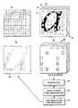
- FIG. 1is a pictorial representation of a two-dimensional field of view from an aircraft carrying a computerized airborne multicamera imaging system (CAMIS) showing four spectral bands of image planes obtained by four progressive scan synchronized CCD cameras;
- CAMIScomputerized airborne multicamera imaging system
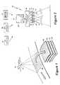
- FIG. 2is a block diagram of the CAMIS employed in the aircraft in FIG. 1 ;
- FIG. 3is a schematic of the pixel factors of a CCD imager
- FIG. 4shows a perspective view of the alignment of four bands of images from four camera directly superimposed one band over one band
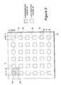
- FIG. 5shows a half-pixel offset alignment of four bands of images from four cameras
- FIG. 6shows the imaging geometry of an interline transfer CCD imager and the original scene restoration
- FIG. 6 ( a )shows a simulation of taking the image of “a” using an IT CCD imager where an array of squares are the photo-sensing elements
- FIG. 6 ( b )shows an actual image of the letter “a” on 5 ⁇ 5 photosites of the IT CCD imager which is digitized and sent to a computer system;
- FIG. 6 ( c )shows the image format commonly displayed by the computer system for the 5 ⁇ 5 photosites image of “a”;
- FIG. 6 ( d )shows a resampling-up operation to redistribute the sensing data in order to restore the original scene and resolution by doubling the pixel numbers in both row and columns dimensions;
- FIG. 7shows a graphic/flow chart for high-resolution, larger-format imaging using four bands of interline transfer CCD cameras that are optically aligned with half-pixel offset and a flow chart for high-resolution image reduction;
- FIG. 8is a flow chart of a resampling-up subroutine using a neighbor average interpolation (NAI) algorithm
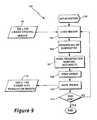
- FIG. 9is a flow chart of a high-resolution multispectral image batch processing program using pixel precision registration after resampling-up algorithm.
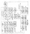
- FIG. 10is a detailed block diagram of the CAMIS computer system showing the sensor head and the data flows from the sensors to the computer system.
- FIG. 1a pictorial representation of an aircraft 26 employing the invention is shown.
- the invention of a computerized airborne multicamera imaging system (CAMIS) 10is shown having spatial resolution enhancement and dynamic range extension integrated for photographic framing-type spectral imaging.
- the CAMIS 10acquires earth surface images 28 from air or space with a two-dimensional field of view and generates imagery from four channels of synchronized video sources.
- the earth surface images 28are transformed into four user selective spectral bands 30 , 32 , 34 , 36 within the 400-1000 nm spectral range.
- FIG. 2a block diagram of the CAMIS 10 is shown comprising a sensor head 11 , an integrated computer system 22 including a differential (GPS) (not shown).
- the sensor head 11comprises four synchronized Sony XC-8500CE 1 ⁇ 2′′ black-and-white progressive scan CCD video cameras 12 , 13 , 14 , 15 with 782 ⁇ 576 effective square pixels each.
- interchangeable narrow band interference filters 18 , 19 , 20 , 21By attaching interchangeable narrow band interference filters 18 , 19 , 20 , 21 to the front of the lens of each of the cameras 12 , 13 , 14 , 15 , four user-selectable spectral bands within the 400-1000 nm spectral range, such as blue, green, red, and near infrared (NIR) at 450, 550, 650, and 800 nm respectively with bandwidth 10nm or 25nm each, can be captured with non-compromised color separation.
- NIRnear infrared
- the Sony XC-8500CE camerawas designed for optimum performance in a motion environment.
- the computer system 22comprises mission planning, system automation, interactive operation, and image post-processing software to produce high quality, spatial resolution enhanced, instantaneous-freeze-frame multispectral images.
- a GPS (Global Positioning System) receiversuch as the Motorola Oncore VP, is used for real-time measurement of geodetic position of the CAMIS 10 platform.
- the Oncore VPreceives signals from 8 GPS satellites ( 40 , 42 ). However, the GPS accuracy could be intentionally degraded by what U.S. Department of Defense with semi-random errors up to 100 meters along with other systematic errors.
- One method for correcting the errorsis to use “monitors” at known locations (Base Stations) to measure the errors, generate corrections, and send them to other remote GPS receivers, which is called a differential GPS (DGPS) correction.
- the Oncore VPis a differential correction capable receiver which accepts the correction signals.
- An OmniSTAR satellite 44is a satellite fed DGPS service, with many widely-spaced Base Stations for wide area coverage. OmniSTAR 44 (along with its receiver) can improve the accuracy of a GPS receiver by as much as 100 times. It is a real-time system that can achieve sub-meter accuracy over most land areas worldwide.
- the Oncore VPis compatible with the Omnistar receiver.
- the CAMIS 10is designed as an easy to deploy and operate multispectral imaging system suitable for use with a wide range of manned and unmanned light aerial vehicles to fly flexible paths with flexible configurable resolutions under diverse weather conditions.
- CAMIScan deliver precision geo-referenced framing-type four-band multispectral imagery from low-altitude, e.g. 600 feet, with a few inch resolution, to mid-altitude, e.g. 10,000 feet, for large local area coverage. All the spatial and spectral information of the CAMIS multispectral imagery are acquired simultaneously and instantly and can be delivered to the end user in a short turn around time with little processing required.
- the CAMIS 10is highly automatic, intelligent, and compatible to many light UAVs for total hands-off airborne data acquisition.
- the computer system 22can load the predefined flight plan and watch for regions of interest using an integrated GPS receiver. After the power is switched on, it can automatically start data acquisition when flying over the predefined flight tracks. It also automatically adjusts the exposure of the cameras 12 - 15 to fit the perceived imaging signals of the scene according to a built-in real-time histogram feature, and records the exposure settings, which are important for radiometric calibration. For automatic operation, it is not necessary to connect a monitor, a keyboard and/or a mouse.
- CAMIS 10records the flight path flown and the area imaged by using GPS and moving map capability, to provide mission documentation and confirmation of mission objective.
- Basic software features integrated into the computer system 22include mission plan, mission automation, computerized exposure control, GPS timing signal triggered captures, and multi-window visualizations of the live image, moving map, histogram and GPS status on Microsoft WindowsNT environment for interactive data acquisition. Additional software features for the system include batch processing for GIS-compatible image geo-reference, quick-dirty automatic mosaicking, and timely data delivery with original GPS tags.
- the CAMIS sensor head 11comprising the four Sony XC-8500CE interline transfer, black-and-white progressive scan, CCD video cameras 12 - 15 with 782 ⁇ 576 square pixels each, provides a total of 1.82 million effective pixels.
- interchangeable narrow band interference filters 18 - 21on the front optics of each of the cameras 12 - 15 , four user-selectable spectral bands 30 - 36 , such as NIR, red, green, and blue, can be captured with non-compromised color separation.
- These four interline transfer (IT) progressive scan, CCD cameras 12 - 15are synchronized and aligned in parallel with sub-pixel spatial offset tolerance over a common field of view.
- each sensing element of an interline transfer CCDis partially masked with aluminum coating for buried vertical shift registers and the light sensing area fills only 25% of an imaging pixel (shown in FIG. 3 )
- sub-pixel spatial offset permitted in the alignmentis useful for providing spatial resolution enhancement.
- these slight sub-pixel variations in camera alignmentmake the 25% fill area (e.g. a ⁇ a in FIG. 3 ) of each camera pixel see a slightly different detail within a ground pixel (e.g. A ⁇ A in FIG.
- a schematicis shown of pixel factors of CCD imagers 12 - 15 .
- all the pixelsmust appear to be square and to cover the continuous image as pixel 69 .
- the actual pixel sensingmay be different.
- a set of geometry parameters associated with CCD imagers 12 - 15are defined as follows:
- Parameters A and Bare the spacing between two adjacent photo-sensing elements such as elements 60 , 61 and 62 , 63 respectively and represent the sampling distances.
- the parameters a and bare the dimensions of a photo-sensing element 60 , 61 , 62 , 63 , or 64 and represent the sampling distances.
- CCD imagersincluding the interline transfer (IT) CCD imager used by CAMIS 10 , a portion of the camera surface 68 is not sensitive to light.
- the fraction of the surface of the photosensitive region 60 to the total pixel 69 sizeis termed the fill factor and is given by the ratio ab/AB.
- the IT CCD imagers 12 - 15 with square pixel geometrytypically have a 25% fill-factor.
- some IT CCD imagersuse microlenticular arrays overlapped on each photosensitive element. These little lenses focus the light that would normally strike the non-photosensitive areas into regions that are sensitive.
- CAMIS 10uses a measurement grade CCD imager, the Sony XC-8500CD 1 ⁇ 2′′, black-and-white, progressive scan, CCD video cameras with 782 ⁇ 576 square effective pixels each, without using the micro-lenses.
- FIG. 4a perspective view of a non-offset alignment is shown for four bands of images from the four cameras 12 - 15 .
- This non-offset CAMIS 10 alignment strategyrequires that the four cameras 12 - 15 are precisely aligned so that all the four bands 71 - 74 of imaging are superimposed one over one without significant sensing element offset as illustrated in FIG. 4 .
- This alignment methodtakes the four-band image with the same number of sensing dots as those of one band image. Therefore, the spatial content obtainable by this imaging mode will not increase.
- this alignment methodis difficult to be implemented exactly as it is designed because of the real-world errors, which include the optical and mechanical parts tolerance permitted in the manufacture process, and the imperfections of the alignment. In the worst case, these misalignment errors can be as big as 0.5A/B steps.
- a half-pixel offset alignment methodis shown for four bands 81 - 84 of images from the four cameras 12 - 15 .
- the IT CCD imager with square pixel geometrytypically has a fill-factor of 25%.
- the sensing area for a pixelis only a quarter of the pixel area.
- a half-pixel ( ⁇ 0.5A, ⁇ 0.5B) offset alignment method for CAMIS 10has been employed to improve the spatial imaging performance as shown in FIG. 5 .
- the half-pixel alignment methodrequires that the four cameras 12 - 15 are aligned so that all the four bands 81 - 84 of imaging have a half pixel or so offset to each other. (in practice ⁇ 0.5, ⁇ 1.5, and ⁇ 2.5A (or B) offset is allowed). With the same imaging area of a single CCD imager, this method increases the sensing dots of the four-camera image by a factor of four compared to the single camera image. Therefore, the spatial content of the imaging is quadrupled. In other words, the CAMIS 10 that comprises four spectral bands 81 - 84 of progressive scan CCD video cameras 12 - 15 with 782 ⁇ 576 square pixels each gives a total of 1.82 million effective sensing dots using this half-pixel offset camera alignment method.
- the CAMIS 10 with four individual 782 ⁇ 576 square pixel CCD imagers 12 - 15is equivalent to a 1564 ⁇ 1152 single chip CCD imager using half-pixel offset alignment cocept.
- the four imagers 12 - 15comprise the four interchangeable independent narrow band interference filters 18 - 21 . Therefore, CAMIS 10 provides much better color separation and more flexible band configuration than that of any single chip CCD imager achievable.
- the present four CCD imagers 12 - 15can achieve a much better data bandwidth (60 frames of 1564 ⁇ 1152 images per second) than that of a 1564 ⁇ 1152 single chip CCD (best achievable at this movement is 12 frames of 1564 ⁇ 1152 images per second) for high speed remote sensing using jet aircraft or other high speed low altitude platforms.
- FIG. 6depicts a computer simulation for imaging a character “a” using an IT CCD imager.
- FIG. 6 ( b )shows an actual image of the letter “a” on 5 ⁇ 5 photosites of the IT CCD imager which is digitized and sent to a computer system.
- the character “a”is imaged as shown with the actual sensing elements (sized at a ⁇ b, which determines the actual smallest sensing dimension) smaller than a pixel that is defined as A ⁇ B.
- the ordinary computer image format used to display the imagedoes not match the actual imaging.
- FIG. 6 ( c )shows the image format commonly displayed by a computer on the 5 ⁇ 5 photosites of “a”. The computer processes and displays the image using 100% filled pixel assumption which apparently reduces the imaging resolution and fidelity for an IT CCD camera.
- FIG. 6 ( d )shows a resampling-up operation which is used to redistribute the sensing dots in order to restore the original scene and resolution. This operation doubles the pixel numbers in both row and column dimensions.
- FIG. 7a combined graphic/flow chart is shown for high resolution, larger-format imaging using four bands 81 - 84 of interline transfer CCD cameras 12 - 15 that are optically aligned with a half pixel (one sensing element) offset to each other and a flow chart for high-resolution image reduction.
- Original imagesare received from the four individual IT CCD cameras 12 - 15 simultaneously.
- Four bands 91 of images as shown in FIG. 7are the data sources 92 .
- the digitized imagesneed to be resampled-up for example, from 782 ⁇ 576 to 1564 ⁇ 1152, (See FIGS. 6 c and 6 d ) to take advantage of the fine, sub-pixels-sized sensing elements or finaer pixel pitel that permits band shifting for better band-to-band registration
- a neighbor average interpolation (NAI) algorithmprovides an integrated step for two fold resampling-up, which resamples the original four-band 768 ⁇ 576 digital images up to 1536 ⁇ 1152 ones in this case.
- the NAI algorithm stepsare as follows:
- each band of the 768 ⁇ 576 sensed dotsare redistributed to a 1536 ⁇ 576 grid, which consists of odd columns filled with existing data of the sensed dots and even columns inserted as blank space;
- the average value of the pixel data at every two adjacent odd columnsis calculated and then copied to the even column between them;
- each band of the interpolated 1536 ⁇ 576 imageis redistributed to a 1536 ⁇ 1152 grid, which consists of odd rows filled with existing pixel data and blank even rows inserted;
- the average value of the pixelsis calculated at every two adjacent odd rows and copies it to the even rows between them.
- a flow chart of the resampling-up subroutine 120is shown using a neighbor average interpolation (NAI) algorithm.
- NAIneighbor average interpolation
- the original digitized imagesneed to be re-sampled two-folds up to take advantage of the fine, sub-pixels-sized sensing elements of the IT CCD imager for the imaging fidelity and recovering the automally higher or finer spatial definition.
- the interpolation operationis needed to fill the blank rows and columns inserted to make the re-sampled image compatible to computer graphic display format.
- this subroutine 120does two simple operations, data redistribution 124 , 128 for up-scaling and data interpolation 126 , 130 to fill the blank dots. These two operations are executed in sequence for horizontal dimension and vertical dimension respectively.
- the NAI algorithmis compatible with the continuous tone natures of the Earth scene and hence can restore the original scene for Earth remote sensing in general and get the spatial resolution enhanced.
- a lens geometric correction or calibration stepcan be added as an optional procedure for each band using a third party subroutine such as is provided in the Matrox Imaging Library Version 6.1.
- the band-to-band pixel registration 94which shifts different,bands in 0.5A, 0.5B steps to make all bands (originally have offsets of ⁇ 0.5A(B), ⁇ 1.5 A(B), ⁇ 2.5A(B), . . . ) superimposed precisely, of the multispectral data superimposition operation is performed to complete the high-resolution precision image restoration 95 .
- the output format of the spatial resolution enhanced imageis 1520(H) ⁇ 1140(V) ⁇ 4(Bytes), which amounts to 7.0 Mbytes.
- the band-to-band pixel registration 94can be done more accurately, with half pixel stepped 0.5A or 0.5B accuracy per dimension referring to the original captures.
- the resampling-up operationrequires the camera to be well aligned with half-pixel offset without significant errors, so that the fold of the resampling-up is fixed as two in either horizontal or vertical dimensions.
- the folds of resampling-upmay need to be increased to bigger than two. Therefore, the band-to-band pixel registration 94 can be adjusted at a level even less than a half-pixel in each dimension. This method is referred to as Precision Registration After Resampling-up (PRAR).
- PRARPrecision Registration After Resampling-up
- FIG. 9a flow chart of a high-resolution multispectral image batch processing program 100 is shown using a pixel precision registration after resampling-up (PRAR) algorithm.
- the batch processing programfirst initializes 102 for memory allocation, image array parameter definitions, and pixel registration parameters retrieved via Windows graphic user interfaces (GUI). Next, it loads the first image file 104 into the memory, and initiates the resampling-up subroutine 106 to resample image-up using NAI algorithm ( FIG. 8 ) for the subroutine.
- GUIWindows graphic user interfaces
- the pixel registrationis performed followed by shift bands in the subpixel pitch shifting with increased precision using smaller quantum steps or finer pitch (1 ⁇ 2 original pixel step for two fold resampling-up) within the resampled-up image format (1536 ⁇ 1152 ⁇ 4 bands).
- the shifting band operationwith the shift distance of 0.5A(B), 1.5A(B), . . . depending on the original camera mounting condition for band-to-band registration will make the image bigger than 1536 ⁇ 1152 and the edge columns and rows with band loses or color missing. Therefore, these edges need to be cropped.
- After cropping edges 108 the processed, spatial resolution enhanced, larger format images 112are saved in a computer graphic file format.
- the program 100checks if there are any unprocessed 768 ⁇ 576 ⁇ 4 band image files left in the computer hard disk for processing. If yes, a new file is fetched to process. The program 100 keeps processing image files in the loop until the complete batch job done.
- the CAMIS sensor head 11comprises the four low noise, high performance black-and-white progressive scan CCD cameras with signal to noise ratio of 60 dB and a variable speed electronic shutter for each camera 12 - 15 .
- the CCD camera 12 - 15can be triggered to capture a full-frame still image with precision GPS timing and its capture integration time (exposure) can be controlled from 1/50th second to 1/10,000th second by external electronic signals.
- These external electronic signalsare supplied by the CAMIS computer system 22 and the effective time of exposure is controlled by computer programs.
- the dynamic range in a digital imaging system like CAMISrelates to both the noise present in the sensor head 11 and the accuracy of the analog to digital (A/D) converters in the computer system 22 .
- the signal to noise ratio of each of the cameras 12 - 15 of 60 dBis equivalent to 10-bits.
- the CAMIS digitizerconsists of four 8-bit A/D converters 172 - 174 . Therefore, the limiting factor or physical boundary of the dynamic range of CAMIS 10 is simply the size of the quantization step of these A/D converters, which limits the system dynamic range as 8-bit (or 256 different discernable levels) per channel per snapshot.
- CAMIS 10controls the exposure time appropriately to acquire a desired signal while rejecting all the rest.
- the choice of exposure factoris generally assisted by the real-time histogram analysis capacity of the system. For example, when imaging over a region of interest, the computer can be programmed to set up an appropriate exposure that permits no more than 1% of the pixels to have an intensity bigger than 8 bits or 255 in digital number. In addition to an exposure strategy that keeps pixel saturation to a minimum, it is also possible to set up an exposure that makes the peak of the pixel histogram sit in the middle range. This exposure strategy is best suited for imaging faint objects that dominate in a region of interest.
- a single capturehas certain limitations when trying to accommodate simultaneously very weak and very strong signals.
- the dynamic range of signal intensity distribution in a single imagecan be much larger than 256 discernable levels, for example, in an image with bright tones and shadows. It often happens that exposures that are optimized for capturing darker regions lose the bright ones, or that capturing brighter areas loses the darker ones, such as in the case of flying over a coastal region with dark water and bright sand using an 8-bit per channel snapshot.
- the exposure set determined by the pre-shooting histogram analysisis right for the beach but underexposes for the water, so the water is all shadow and has no detail.
- CAMIS 10is enhanced with the capacity of acquiring a bracket of computer-controlled exposures, each of which freezes all the four-band spatial and spectral information simultaneously and instantaneously with a designated exposure setting. It permits the user to set two extra exposures using a Windows dialogue box control, which sets two pre-determined quantities for the increment and decrement. For example, the first exposure is set by a pre-shooting computer-assisted histogram analysis, the second and the third snapshots are set with 50% (or other) increment and 50% (or other) decrement exposures for exposure compensations or dynamic range extending. Thus, for every trigger, the CAMIS 10 will automatically bracket the image with three snapshots, one having more exposure, one having less, and one in the middle.
- bracketed snapshotsare buffered in a memory of computer system 22 at a fast rate (80 msec interval) and then transferred to a hard drive 166 of computer system 22 and saved in TIFF format.
- the bracketed exposure seriescompose an integrated data set that contains improved radiometric details for all the bright and dark fields in a scene.
- CAMIS computer system 22including the sensor head 11 comprising four imagers or cameras 12 , 13 , 14 , and 15 which feed multispectral image data to the computer system 22 .
- the computer system 22comprises a sensor interface 151 , which includes 8-bit A/D converters 171 - 174 , for digitizing the multispectral image data from the sensor head 11 .
- the digitized image datais fed to a VGA interface 152 for display on LCD monitor 24 and fed to an on-board processing unit 154 .
- the multispectral bands of imagesare stored in local SDRAMS 156 during various processing operations.
- the resampling-up routine 106 and the band-to-band pixel registration routine 92are stored in hard drive 166 . These routines are processed by a Pentium III CPU 158 with 512 MB SDRAM via a Host PCI (Peripheral Component Interconnect) bus 164 . Data transfers occur via the PCI bus 164 , and a PCI to PCI bridge 162 interfaces the Pentium III CPU 158 to the PCI bus 164 . Also, a PCI to PCI bridge 160 interfaces the video display interface 152 and the on-board processing unit 154 to the PCI bus 164 .
- PCIPeripheral Component Interconnect
- the dedicated airborne imaging computer system 22is designed to interface the cameras 12 - 15 for real-time numerical control and digital imaging.
- the computer system 22may be embodied by an Intel Pentium III 800MHz CPU with 512 Mbyte SDRAM 158 , a Matrox Genesis image processing card with 64 MB SDRAM on board 156 , a differential capable GPS receiver 180 , a 40 GByte hard drive 166 , and fast Ethernet 182 and SCSI interfaces 184 and packaged into a compact computer chassis, which is sized half a standard desktop PC weighing less than 20 pounds and having a power consumption less than 150W running under Windows NT 4.0 or higher.
- the computerpowers and synchronizes the four cameras 12 - 15 and digitizes the four-channel video data stream simultaneously for snapshot imaging.
- the cameras 12 - 15are packaged as a rugged, pocket-sized remote sensor head 11 , which is small enough to be fitted at any convenient location of an aerial platform.
- the Matrox processing card and related software with 64 MB SDRAM 156 , the 8-bit A/D/converters 171 - 174 , and the video interface 155are manufactured by Matrox Electronic Systems, Ltd. of Dorval, Quebec, Canada.
- the CAMIS 10is capable of delivering geo-referenced four-band multispectral imagery from a low-altitude, e.g. 600 feet, with a few inch resolution, to a mid-altitude, e.g. 10,000 feet, for large local area coverage.
- CAMIS multispectral imageryachieves more precise band-to-band pixel registration with sub-pixel accuracy, higher spatial resolution in an output format of 1540(H) ⁇ 1140(V) ⁇ 32 (bits) for four bands.
- CAMIS 10is enhanced with the capacity of bracketing one computed exposure with two additional up/down-stepped ones, each of which freezes all the four-band spatial and spectral information simultaneously and instantaneously. With bracketed multiple exposures, CAMIS effectively extends its dynamic range of the measurement.
Landscapes
- Engineering & Computer Science (AREA)
- Multimedia (AREA)
- Signal Processing (AREA)
- Studio Devices (AREA)
- Image Processing (AREA)
- Color Television Image Signal Generators (AREA)
Abstract
Description
Claims (6)
Priority Applications (1)
| Application Number | Priority Date | Filing Date | Title |
|---|---|---|---|
| US09/838,712US7019777B2 (en) | 2000-04-21 | 2001-04-19 | Multispectral imaging system with spatial resolution enhancement |
Applications Claiming Priority (2)
| Application Number | Priority Date | Filing Date | Title |
|---|---|---|---|
| US19898600P | 2000-04-21 | 2000-04-21 | |
| US09/838,712US7019777B2 (en) | 2000-04-21 | 2001-04-19 | Multispectral imaging system with spatial resolution enhancement |
Publications (2)
| Publication Number | Publication Date |
|---|---|
| US20020012071A1 US20020012071A1 (en) | 2002-01-31 |
| US7019777B2true US7019777B2 (en) | 2006-03-28 |
Family
ID=26894341
Family Applications (1)
| Application Number | Title | Priority Date | Filing Date |
|---|---|---|---|
| US09/838,712Expired - Fee RelatedUS7019777B2 (en) | 2000-04-21 | 2001-04-19 | Multispectral imaging system with spatial resolution enhancement |
Country Status (1)
| Country | Link |
|---|---|
| US (1) | US7019777B2 (en) |
Cited By (39)
| Publication number | Priority date | Publication date | Assignee | Title |
|---|---|---|---|---|
| US20040257441A1 (en)* | 2001-08-29 | 2004-12-23 | Geovantage, Inc. | Digital imaging system for airborne applications |
| US20050162525A1 (en)* | 2004-01-23 | 2005-07-28 | Pentax Corporation | Remote-control device for digital camera |
| US20060077275A1 (en)* | 2004-10-11 | 2006-04-13 | Nucore Technology Inc. | Processor-controlled timing generator for multiple image sensors |
| US20070153099A1 (en)* | 2005-12-22 | 2007-07-05 | Mitsuharu Ohki | Image signal processing apparatus, imaging apparatus, image signal processing method and computer program thereof |
| US20080055450A1 (en)* | 2006-03-03 | 2008-03-06 | Fujifilm Corporation | Multi-plate solid-state imager module and apparatus |
| US7418320B1 (en)* | 2005-01-24 | 2008-08-26 | International Business Machines Corporation | Navigating a UAV having an on-board digital camera to capture desired geographic area |
| US20080309801A1 (en)* | 2002-07-10 | 2008-12-18 | Cuccias Frank J | Infrared camera system and method |
| US20090256909A1 (en)* | 2008-04-11 | 2009-10-15 | Nixon Stuart | Systems and methods of capturing large area images in detail including cascaded cameras and/or calibration features |
| US20090278929A1 (en)* | 2008-05-06 | 2009-11-12 | Flir Systems Inc | Video camera with interchangable optical sensors |
| US20090295924A1 (en)* | 2002-08-28 | 2009-12-03 | M7 Visual Intelligence, L.P. | Retinal concave array compound camera system |
| WO2010025682A1 (en)* | 2008-09-08 | 2010-03-11 | 中国测绘科学研究院 | Combined wide-angle aerial digital camera system with functions of self-calibration and self-stabilization |
| US20100235095A1 (en)* | 2002-09-20 | 2010-09-16 | M7 Visual Intelligence, L.P. | Self-calibrated, remote imaging and data processing system |
| US20110121989A1 (en)* | 2009-11-24 | 2011-05-26 | Symbol Technologies, Inc. | Remote sensing system |
| USRE43239E1 (en)* | 2004-09-07 | 2012-03-13 | Intellectual Ventures Ii Llc | Color interpolation method of image sensor |
| US20120300064A1 (en)* | 2011-04-25 | 2012-11-29 | Skybox Imaging, Inc. | Systems and methods for overhead imaging and video |
| US8497905B2 (en) | 2008-04-11 | 2013-07-30 | nearmap australia pty ltd. | Systems and methods of capturing large area images in detail including cascaded cameras and/or calibration features |
| US20130250105A1 (en)* | 2012-03-22 | 2013-09-26 | Exelis, Inc. | Algorithm for adaptive downsampling to an irregular grid |
| US8860942B1 (en) | 2011-04-29 | 2014-10-14 | The United States Of America As Represented By The Secretary Of The Air Force | Apparatus for multi-spectral imaging of point event detection |
| RU2533438C2 (en)* | 2012-09-04 | 2014-11-20 | Открытое акционерное общество "Швабе - Технологическая лаборатория" | Method of generating spectrozonal video frames and apparatus therefor |
| US8994822B2 (en) | 2002-08-28 | 2015-03-31 | Visual Intelligence Lp | Infrastructure mapping system and method |
| US9041822B2 (en) | 2011-02-11 | 2015-05-26 | Canadian Space Agency | Method and system of increasing spatial resolution of multi-dimensional optical imagery using sensor's intrinsic keystone |
| US20150356373A1 (en)* | 2013-09-11 | 2015-12-10 | Digitalglobe, Inc. | Automated and scalable object and feature extraction from imagery |
| US9241127B2 (en) | 2013-03-14 | 2016-01-19 | Samsung Electronics Co., Ltd. | Wide dynamic range image processing method and image signal processor using the same |
| CN105526916A (en)* | 2014-09-29 | 2016-04-27 | 波音公司 | System and method for dynamic image masking |
| WO2018036285A1 (en)* | 2016-08-22 | 2018-03-01 | 亿航智能设备(广州)有限公司 | Method and apparatus for realizing self-photographing based on aerial vehicle |
| US9946165B2 (en) | 2013-10-02 | 2018-04-17 | Asml Netherlands B.V. | Methods and apparatus for obtaining diagnostic information relating to an industrial process |
| US9945828B1 (en) | 2015-10-23 | 2018-04-17 | Sentek Systems Llc | Airborne multispectral imaging system with integrated navigation sensors and automatic image stitching |
| US10057509B2 (en) | 2014-05-30 | 2018-08-21 | Flir Systems, Inc. | Multiple-sensor imaging system |
| US10230925B2 (en) | 2014-06-13 | 2019-03-12 | Urthecast Corp. | Systems and methods for processing and providing terrestrial and/or space-based earth observation video |
| CN110009688A (en)* | 2019-03-19 | 2019-07-12 | 北京市遥感信息研究所 | A kind of infrared remote sensing image relative radiometric calibration method, system and remote sensing platform |
| US10615513B2 (en) | 2015-06-16 | 2020-04-07 | Urthecast Corp | Efficient planar phased array antenna assembly |
| US10871561B2 (en) | 2015-03-25 | 2020-12-22 | Urthecast Corp. | Apparatus and methods for synthetic aperture radar with digital beamforming |
| US10955546B2 (en) | 2015-11-25 | 2021-03-23 | Urthecast Corp. | Synthetic aperture radar imaging apparatus and methods |
| WO2021067475A1 (en) | 2019-09-30 | 2021-04-08 | Akoya Biosciences, Inc. | Multiplexed imaging with enzyme mediated amplification |
| US11017503B2 (en)* | 2010-12-20 | 2021-05-25 | Microsoft Technology Licensing , LLC | Techniques for atmospheric and solar correction of aerial images |
| USRE49105E1 (en) | 2002-09-20 | 2022-06-14 | Vi Technologies, Llc | Self-calibrated, remote imaging and data processing system |
| US11378682B2 (en) | 2017-05-23 | 2022-07-05 | Spacealpha Insights Corp. | Synthetic aperture radar imaging apparatus and methods for moving targets |
| US11506778B2 (en) | 2017-05-23 | 2022-11-22 | Spacealpha Insights Corp. | Synthetic aperture radar imaging apparatus and methods |
| US11525910B2 (en) | 2017-11-22 | 2022-12-13 | Spacealpha Insights Corp. | Synthetic aperture radar apparatus and methods |
Families Citing this family (89)
| Publication number | Priority date | Publication date | Assignee | Title |
|---|---|---|---|---|
| US8022969B2 (en) | 2001-05-09 | 2011-09-20 | Samsung Electronics Co., Ltd. | Rotatable display with sub-pixel rendering |
| US7283142B2 (en) | 2000-07-28 | 2007-10-16 | Clairvoyante, Inc. | Color display having horizontal sub-pixel arrangements and layouts |
| US6950115B2 (en) | 2001-05-09 | 2005-09-27 | Clairvoyante, Inc. | Color flat panel display sub-pixel arrangements and layouts |
| WO2002011112A2 (en) | 2000-07-28 | 2002-02-07 | Clairvoyante Laboratories, Inc. | Arrangement of color pixels for full color imaging devices with simplified addressing |
| US7274383B1 (en)* | 2000-07-28 | 2007-09-25 | Clairvoyante, Inc | Arrangement of color pixels for full color imaging devices with simplified addressing |
| US6477326B1 (en)* | 2000-08-31 | 2002-11-05 | Recon/Optical, Inc. | Dual band framing reconnaissance camera |
| US7009638B2 (en)* | 2001-05-04 | 2006-03-07 | Vexcel Imaging Gmbh | Self-calibrating, digital, large format camera with single or multiple detector arrays and single or multiple optical systems |
| US7307646B2 (en) | 2001-05-09 | 2007-12-11 | Clairvoyante, Inc | Color display pixel arrangements and addressing means |
| US7184066B2 (en) | 2001-05-09 | 2007-02-27 | Clairvoyante, Inc | Methods and systems for sub-pixel rendering with adaptive filtering |
| US7221381B2 (en) | 2001-05-09 | 2007-05-22 | Clairvoyante, Inc | Methods and systems for sub-pixel rendering with gamma adjustment |
| US7123277B2 (en) | 2001-05-09 | 2006-10-17 | Clairvoyante, Inc. | Conversion of a sub-pixel format data to another sub-pixel data format |
| AU2002353139A1 (en) | 2001-12-14 | 2003-06-30 | Clairvoyante Laboratories, Inc. | Improvements to color flat panel display sub-pixel arrangements and layouts with reduced visibility of a blue luminance well |
| US20040051724A1 (en)* | 2002-09-13 | 2004-03-18 | Elliott Candice Hellen Brown | Four color arrangements of emitters for subpixel rendering |
| US7417648B2 (en) | 2002-01-07 | 2008-08-26 | Samsung Electronics Co. Ltd., | Color flat panel display sub-pixel arrangements and layouts for sub-pixel rendering with split blue sub-pixels |
| US7424133B2 (en)* | 2002-11-08 | 2008-09-09 | Pictometry International Corporation | Method and apparatus for capturing, geolocating and measuring oblique images |
| US7046256B2 (en) | 2003-01-22 | 2006-05-16 | Clairvoyante, Inc | System and methods of subpixel rendering implemented on display panels |
| DE10307744A1 (en)* | 2003-02-24 | 2004-09-02 | Carl Zeiss Jena Gmbh | Electromagnetic radiation intensity determination method in which measurements of radiation originating from particular locations are normalized based on the length of an intensity recording exposure |
| US20040196302A1 (en)* | 2003-03-04 | 2004-10-07 | Im Moon Hwan | Systems and methods for temporal subpixel rendering of image data |
| US6917368B2 (en) | 2003-03-04 | 2005-07-12 | Clairvoyante, Inc. | Sub-pixel rendering system and method for improved display viewing angles |
| US7167186B2 (en) | 2003-03-04 | 2007-01-23 | Clairvoyante, Inc | Systems and methods for motion adaptive filtering |
| US7352374B2 (en)* | 2003-04-07 | 2008-04-01 | Clairvoyante, Inc | Image data set with embedded pre-subpixel rendered image |
| US7230584B2 (en)* | 2003-05-20 | 2007-06-12 | Clairvoyante, Inc | Projector systems with reduced flicker |
| US20040233308A1 (en)* | 2003-05-20 | 2004-11-25 | Elliott Candice Hellen Brown | Image capture device and camera |
| US7268748B2 (en)* | 2003-05-20 | 2007-09-11 | Clairvoyante, Inc | Subpixel rendering for cathode ray tube devices |
| WO2005112566A2 (en) | 2004-05-01 | 2005-12-01 | Neocific, Inc. | Methods and apparatus for multi-carrier communications with variable channel bandwidth |
| US7773799B2 (en)* | 2004-04-02 | 2010-08-10 | The Boeing Company | Method for automatic stereo measurement of a point of interest in a scene |
| US7751651B2 (en)* | 2004-04-02 | 2010-07-06 | The Boeing Company | Processing architecture for automatic image registration |
| US8055100B2 (en)* | 2004-04-02 | 2011-11-08 | The Boeing Company | Method and system for image registration quality confirmation and improvement |
| US20050250821A1 (en)* | 2004-04-16 | 2005-11-10 | Vincent Sewalt | Quaternary ammonium compounds in the treatment of water and as antimicrobial wash |
| WO2005119012A1 (en)* | 2004-06-03 | 2005-12-15 | Goodrich Pump & Engine Control Systems, Inc. | Overspeed limiter for turboshaft engines |
| US20050285947A1 (en)* | 2004-06-21 | 2005-12-29 | Grindstaff Gene A | Real-time stabilization |
| WO2006078310A2 (en)* | 2004-06-25 | 2006-07-27 | Digitalglobe, Inc. | Method and apparatus for determining a location associated with an image |
| US7567731B2 (en)* | 2004-07-15 | 2009-07-28 | Harris Corporation | Method and system for simultaneously registering multi-dimensional topographical points |
| BRPI0514078A (en)* | 2004-08-04 | 2008-05-27 | Intergraph Software Tech Co | method of preparing a composite image with non-uniform resolution |
| US20060126959A1 (en)* | 2004-12-13 | 2006-06-15 | Digitalglobe, Inc. | Method and apparatus for enhancing a digital image |
| US7561731B2 (en)* | 2004-12-27 | 2009-07-14 | Trw Automotive U.S. Llc | Method and apparatus for enhancing the dynamic range of a stereo vision system |
| US20060170956A1 (en) | 2005-01-31 | 2006-08-03 | Jung Edward K | Shared image devices |
| US9093121B2 (en) | 2006-02-28 | 2015-07-28 | The Invention Science Fund I, Llc | Data management of an audio data stream |
| US10003762B2 (en) | 2005-04-26 | 2018-06-19 | Invention Science Fund I, Llc | Shared image devices |
| US9451200B2 (en)* | 2005-06-02 | 2016-09-20 | Invention Science Fund I, Llc | Storage access technique for captured data |
| US7782365B2 (en)* | 2005-06-02 | 2010-08-24 | Searete Llc | Enhanced video/still image correlation |
| US8964054B2 (en)* | 2006-08-18 | 2015-02-24 | The Invention Science Fund I, Llc | Capturing selected image objects |
| US20070109411A1 (en)* | 2005-06-02 | 2007-05-17 | Searete Llc, A Limited Liability Corporation Of The State Of Delaware | Composite image selectivity |
| US9967424B2 (en)* | 2005-06-02 | 2018-05-08 | Invention Science Fund I, Llc | Data storage usage protocol |
| US20070222865A1 (en) | 2006-03-15 | 2007-09-27 | Searete Llc, A Limited Liability Corporation Of The State Of Delaware | Enhanced video/still image correlation |
| US9076208B2 (en)* | 2006-02-28 | 2015-07-07 | The Invention Science Fund I, Llc | Imagery processing |
| US9621749B2 (en)* | 2005-06-02 | 2017-04-11 | Invention Science Fund I, Llc | Capturing selected image objects |
| US20070139529A1 (en)* | 2005-06-02 | 2007-06-21 | Searete Llc, A Limited Liability Corporation Of The State Of Delaware | Dual mode image capture technique |
| US20070008326A1 (en)* | 2005-06-02 | 2007-01-11 | Searete Llc, A Limited Liability Corporation Of The State Of Delaware | Dual mode image capture technique |
| US8681225B2 (en)* | 2005-06-02 | 2014-03-25 | Royce A. Levien | Storage access technique for captured data |
| US9942511B2 (en) | 2005-10-31 | 2018-04-10 | Invention Science Fund I, Llc | Preservation/degradation of video/audio aspects of a data stream |
| US7660430B2 (en)* | 2005-05-23 | 2010-02-09 | Digitalglobe, Inc. | Method and apparatus for determination of water pervious surfaces |
| US20060274153A1 (en)* | 2005-06-02 | 2006-12-07 | Searete Llc, A Limited Liability Corporation Of The State Of Delaware | Third party storage of captured data |
| US7580591B2 (en)* | 2005-07-01 | 2009-08-25 | The Boeing Company | Method for generating a synthetic perspective image |
| US7964835B2 (en) | 2005-08-25 | 2011-06-21 | Protarius Filo Ag, L.L.C. | Digital cameras with direct luminance and chrominance detection |
| US7783406B2 (en) | 2005-09-22 | 2010-08-24 | Reagan Inventions, Llc | System for controlling speed of a vehicle |
| US8189877B2 (en)* | 2005-10-21 | 2012-05-29 | Carnegie Institution Of Washington | Remote sensing analysis of forest disturbances |
| US20070203595A1 (en)* | 2006-02-28 | 2007-08-30 | Searete Llc, A Limited Liability Corporation | Data management of an audio data stream |
| US8581981B2 (en)* | 2006-04-28 | 2013-11-12 | Southwest Research Institute | Optical imaging system for unmanned aerial vehicle |
| WO2008074019A2 (en)* | 2006-12-13 | 2008-06-19 | Georgia Tech Research Corporation | Systems and methods for real time multispectral imaging |
| DE102007009664B3 (en)* | 2007-02-22 | 2008-04-10 | Jena-Optronik Gmbh | Line camera calibrating device for e.g. remote sensing of ground from flight path, has calibration plate provided for repeatedly providing defined radiation intensity, which partially shades image beam path of one of image acquisition units |
| US20090027417A1 (en)* | 2007-07-24 | 2009-01-29 | Horsfall Joseph B | Method and apparatus for registration and overlay of sensor imagery onto synthetic terrain |
| DE102007058943A1 (en)* | 2007-12-07 | 2009-06-10 | Emt Ingenieurgesellschaft Dipl.-Ing. Hartmut Euer Mbh | Multi-spectral video device for air-based surveillance and real time aerial photograph monitoring of uncrewed aircraft, has electronic mosaic/fusion device designed such that fusion device receives image signals of video scanner cameras |
| KR20090120159A (en)* | 2008-05-19 | 2009-11-24 | 삼성전자주식회사 | Image Synthesis Device and Image Synthesis Method |
| JP5445235B2 (en)* | 2010-03-09 | 2014-03-19 | ソニー株式会社 | Image processing apparatus, image processing method, and program |
| EP2559254B1 (en)* | 2010-04-13 | 2019-01-02 | Fraunhofer-Gesellschaft zur Förderung der angewandten Forschung e.V. | Interpolation filter in a hybrid video decoder and encoder |
| JP2012029269A (en)* | 2010-06-21 | 2012-02-09 | Sanyo Electric Co Ltd | Imaging apparatus and projection type image display device |
| US10168153B2 (en) | 2010-12-23 | 2019-01-01 | Trimble Inc. | Enhanced position measurement systems and methods |
| US9879993B2 (en) | 2010-12-23 | 2018-01-30 | Trimble Inc. | Enhanced bundle adjustment techniques |
| US8953012B2 (en)* | 2012-02-13 | 2015-02-10 | Raytheon Company | Multi-plenoptic system with image stacking and method for wide field-of-regard high-resolution imaging |
| US10740608B2 (en)* | 2012-06-13 | 2020-08-11 | San Diego State University Research Foundation | Wide area intermittent video using non-orthorectified feature matching in long period aerial image capture with pixel-based georeferencing |
| US9235763B2 (en)* | 2012-11-26 | 2016-01-12 | Trimble Navigation Limited | Integrated aerial photogrammetry surveys |
| FR3006296B1 (en)* | 2013-05-31 | 2016-11-11 | Airinov | DRONE COMPRISING A MULTISPECTRAL IMAGE DEVICE FOR THE GENERATION OF MAPS REPRESENTING A PLANT STATE OF A CULTURE |
| US9247239B2 (en) | 2013-06-20 | 2016-01-26 | Trimble Navigation Limited | Use of overlap areas to optimize bundle adjustment |
| FR3015740B1 (en)* | 2013-12-20 | 2016-02-05 | Centre Nat Etd Spatiales | METHOD, DEVICE AND SYSTEM FOR PROCESSING CORRECTION OF IMAGES |
| US9460499B2 (en)* | 2014-05-30 | 2016-10-04 | Shenzhen Mindray Bio-Medical Electronics Co., Ltd. | Systems and methods for selective enhancement of a region of interest in an image |
| JP2017034656A (en)* | 2015-08-04 | 2017-02-09 | ソニー・オリンパスメディカルソリューションズ株式会社 | Medical imaging apparatus, medical image acquisition system and endoscope device |
| CN105551053A (en)* | 2015-12-01 | 2016-05-04 | 中国科学院上海技术物理研究所 | Fast geometric precise correction method of mini-planar array satellite-borne TDI CCD camera |
| CN105572689B (en)* | 2016-03-21 | 2017-12-12 | 上海同繁勘测工程科技有限公司 | A kind of narrow-band multispectral camera array imaging device |
| CN107152926B (en)* | 2016-07-18 | 2018-08-24 | 哈尔滨工业大学 | A kind of satellite quickly rotates super large breadth sweeping imaging method |
| CA3048632A1 (en)* | 2016-12-27 | 2018-07-05 | Urugus S.A. | Hyper-spectral imaging when observed object is still |
| WO2018137122A1 (en)* | 2017-01-24 | 2018-08-02 | 深圳企管加企业服务有限公司 | Multispectral imaging system |
| US10586349B2 (en) | 2017-08-24 | 2020-03-10 | Trimble Inc. | Excavator bucket positioning via mobile device |
| CN110392244B (en)* | 2018-04-18 | 2021-03-12 | 长光卫星技术有限公司 | Method for synthesizing color image by three-linear-array camera image |
| CN109856080B (en)* | 2018-12-14 | 2020-08-18 | 华南理工大学 | Near-infrared multispectral imaging multi-index collaborative nondestructive evaluation method for freshness of fish fillet |
| CN110361017B (en)* | 2019-07-19 | 2022-02-11 | 西南科技大学 | A full traversal path planning method for sweeping robot based on grid method |
| US10943360B1 (en) | 2019-10-24 | 2021-03-09 | Trimble Inc. | Photogrammetric machine measure up |
| CN113466142B (en)* | 2021-06-17 | 2023-04-21 | 塔里木大学 | A quantitative detection method of multi-scale fruit scattering polarization spectrum imaging |
| CN114092534B (en)* | 2021-11-19 | 2022-08-30 | 哈尔滨工业大学 | Hyperspectral image and laser radar data registration method and registration system |
Citations (10)
| Publication number | Priority date | Publication date | Assignee | Title |
|---|---|---|---|---|
| US5099317A (en)* | 1988-09-28 | 1992-03-24 | Kabushiki Kaisha Toshiba | Video camera apparatus using a plurality of imaging devices |
| US5289269A (en)* | 1991-12-27 | 1994-02-22 | Nippon Television Network Corporation | Color television camera with details of luminance signal formation |
| US5414465A (en)* | 1993-01-14 | 1995-05-09 | Sony Corporation | Luminance signal generator with interpolation |
| US5541653A (en)* | 1993-07-27 | 1996-07-30 | Sri International | Method and appartus for increasing resolution of digital color images using correlated decoding |
| US5602588A (en)* | 1992-07-22 | 1997-02-11 | Matsushita Electric Industrial Co., Ltd. | Image pickup apparatus having a horizontal line interpolation function |
| US5640206A (en)* | 1994-05-31 | 1997-06-17 | Victor Company Of Japan, Ltd. | Imaging apparatus including offset pixels for generating vertical high frequency component |
| US5790188A (en) | 1995-09-07 | 1998-08-04 | Flight Landata, Inc. | Computer controlled, 3-CCD camera, airborne, variable interference filter imaging spectrometer system |
| US6204881B1 (en)* | 1993-10-10 | 2001-03-20 | Canon Kabushiki Kaisha | Image data processing apparatus which can combine a plurality of images at different exposures into an image with a wider dynamic range |
| US6211906B1 (en) | 1995-09-07 | 2001-04-03 | Flight Landata, Inc. | Computerized component variable interference filter imaging spectrometer system method and apparatus |
| US6526430B1 (en)* | 1999-10-04 | 2003-02-25 | Texas Instruments Incorporated | Reconfigurable SIMD coprocessor architecture for sum of absolute differences and symmetric filtering (scalable MAC engine for image processing) |
- 2001
- 2001-04-19USUS09/838,712patent/US7019777B2/ennot_activeExpired - Fee Related
Patent Citations (10)
| Publication number | Priority date | Publication date | Assignee | Title |
|---|---|---|---|---|
| US5099317A (en)* | 1988-09-28 | 1992-03-24 | Kabushiki Kaisha Toshiba | Video camera apparatus using a plurality of imaging devices |
| US5289269A (en)* | 1991-12-27 | 1994-02-22 | Nippon Television Network Corporation | Color television camera with details of luminance signal formation |
| US5602588A (en)* | 1992-07-22 | 1997-02-11 | Matsushita Electric Industrial Co., Ltd. | Image pickup apparatus having a horizontal line interpolation function |
| US5414465A (en)* | 1993-01-14 | 1995-05-09 | Sony Corporation | Luminance signal generator with interpolation |
| US5541653A (en)* | 1993-07-27 | 1996-07-30 | Sri International | Method and appartus for increasing resolution of digital color images using correlated decoding |
| US6204881B1 (en)* | 1993-10-10 | 2001-03-20 | Canon Kabushiki Kaisha | Image data processing apparatus which can combine a plurality of images at different exposures into an image with a wider dynamic range |
| US5640206A (en)* | 1994-05-31 | 1997-06-17 | Victor Company Of Japan, Ltd. | Imaging apparatus including offset pixels for generating vertical high frequency component |
| US5790188A (en) | 1995-09-07 | 1998-08-04 | Flight Landata, Inc. | Computer controlled, 3-CCD camera, airborne, variable interference filter imaging spectrometer system |
| US6211906B1 (en) | 1995-09-07 | 2001-04-03 | Flight Landata, Inc. | Computerized component variable interference filter imaging spectrometer system method and apparatus |
| US6526430B1 (en)* | 1999-10-04 | 2003-02-25 | Texas Instruments Incorporated | Reconfigurable SIMD coprocessor architecture for sum of absolute differences and symmetric filtering (scalable MAC engine for image processing) |
Non-Patent Citations (4)
| Title |
|---|
| "A Dual-Use Airborne Hyperspectral/Multispectral Imaging System for Remote Sensing" by Xiuhong Sun, Patrick L. Coronado, and Fran Stetina; Presented Oct. 1998; http://www.flidata.com/newpage11.htm.* |
| "A Hyperspectral/Multispectral Imaging System and its Image Georeference" by Xiuhong Sun and James J. Baker; http://www.flidata.com/newpage3.htm.* |
| "Computerized Airborne Multicamera Imaging System (CAMIS) and its Four-Camera Applications*", authors Xiuhong Sun, James Baker and Richard Hordon, Presented at 3rd International Airborne Remote Sensing Conference and Exhibition, Jul. 7-10, 1997, Copenhagen, Denmark, pp. II-799 to II-806. |
| "Computerized Airborne Multicamera Imaging System", authors Xiuhong Sun, James Baker and Richard Hordon, Presented 2nd International Airborne Remote Sensing Conf. and Exhibition, San Francisco, CA, Jun. 24-27, 1996, pp. III-803 to III-812. |
Cited By (67)
| Publication number | Priority date | Publication date | Assignee | Title |
|---|---|---|---|---|
| US20040257441A1 (en)* | 2001-08-29 | 2004-12-23 | Geovantage, Inc. | Digital imaging system for airborne applications |
| US20080309801A1 (en)* | 2002-07-10 | 2008-12-18 | Cuccias Frank J | Infrared camera system and method |
| US7477309B2 (en)* | 2002-07-10 | 2009-01-13 | Lockheed Martin Corporation | Infrared camera system and method |
| US8896695B2 (en) | 2002-08-28 | 2014-11-25 | Visual Intelligence Lp | Retinal concave array compound camera system |
| US20090295924A1 (en)* | 2002-08-28 | 2009-12-03 | M7 Visual Intelligence, L.P. | Retinal concave array compound camera system |
| US8994822B2 (en) | 2002-08-28 | 2015-03-31 | Visual Intelligence Lp | Infrastructure mapping system and method |
| US9389298B2 (en) | 2002-09-20 | 2016-07-12 | Visual Intelligence Lp | Self-calibrated, remote imaging and data processing system |
| US8483960B2 (en) | 2002-09-20 | 2013-07-09 | Visual Intelligence, LP | Self-calibrated, remote imaging and data processing system |
| USRE49105E1 (en) | 2002-09-20 | 2022-06-14 | Vi Technologies, Llc | Self-calibrated, remote imaging and data processing system |
| US9797980B2 (en) | 2002-09-20 | 2017-10-24 | Visual Intelligence Lp | Self-calibrated, remote imaging and data processing system |
| US20100235095A1 (en)* | 2002-09-20 | 2010-09-16 | M7 Visual Intelligence, L.P. | Self-calibrated, remote imaging and data processing system |
| US7528863B2 (en)* | 2004-01-23 | 2009-05-05 | Hoya Corporation | Remote-control device for digital camera |
| US20050162525A1 (en)* | 2004-01-23 | 2005-07-28 | Pentax Corporation | Remote-control device for digital camera |
| USRE43239E1 (en)* | 2004-09-07 | 2012-03-13 | Intellectual Ventures Ii Llc | Color interpolation method of image sensor |
| US7557849B2 (en)* | 2004-10-11 | 2009-07-07 | Mediatek Usa Inc | Processor-controlled timing generator for multiple image sensors |
| US20060077275A1 (en)* | 2004-10-11 | 2006-04-13 | Nucore Technology Inc. | Processor-controlled timing generator for multiple image sensors |
| US20060077276A1 (en)* | 2004-10-11 | 2006-04-13 | Nucore Technology, Inc. | Analog front end timing generator (AFE/TG) having a bit slice output mode |
| US7791658B2 (en)* | 2004-10-11 | 2010-09-07 | Media Tek Singapore Pte Ltd. | Analog front end timing generator (AFE/TG) having a bit slice output mode |
| US20080228335A1 (en)* | 2005-01-24 | 2008-09-18 | William Kress Bodin | Navigating a uav having an on-board digital camera to capture desired geographic area |
| US7546187B2 (en)* | 2005-01-24 | 2009-06-09 | International Business Machines Corporation | Navigating a UAV having an on-board digital camera to capture desired geographic area |
| US7418320B1 (en)* | 2005-01-24 | 2008-08-26 | International Business Machines Corporation | Navigating a UAV having an on-board digital camera to capture desired geographic area |
| US20070153099A1 (en)* | 2005-12-22 | 2007-07-05 | Mitsuharu Ohki | Image signal processing apparatus, imaging apparatus, image signal processing method and computer program thereof |
| US20080055450A1 (en)* | 2006-03-03 | 2008-03-06 | Fujifilm Corporation | Multi-plate solid-state imager module and apparatus |
| US20090256909A1 (en)* | 2008-04-11 | 2009-10-15 | Nixon Stuart | Systems and methods of capturing large area images in detail including cascaded cameras and/or calibration features |
| US8497905B2 (en) | 2008-04-11 | 2013-07-30 | nearmap australia pty ltd. | Systems and methods of capturing large area images in detail including cascaded cameras and/or calibration features |
| US10358234B2 (en) | 2008-04-11 | 2019-07-23 | Nearmap Australia Pty Ltd | Systems and methods of capturing large area images in detail including cascaded cameras and/or calibration features |
| US8675068B2 (en) | 2008-04-11 | 2014-03-18 | Nearmap Australia Pty Ltd | Systems and methods of capturing large area images in detail including cascaded cameras and/or calibration features |
| US10358235B2 (en) | 2008-04-11 | 2019-07-23 | Nearmap Australia Pty Ltd | Method and system for creating a photomap using a dual-resolution camera system |
| US20090278929A1 (en)* | 2008-05-06 | 2009-11-12 | Flir Systems Inc | Video camera with interchangable optical sensors |
| WO2010025682A1 (en)* | 2008-09-08 | 2010-03-11 | 中国测绘科学研究院 | Combined wide-angle aerial digital camera system with functions of self-calibration and self-stabilization |
| US8242932B2 (en)* | 2009-11-24 | 2012-08-14 | Symbol Technologies, Inc. | Remote sensing system |
| US20110121989A1 (en)* | 2009-11-24 | 2011-05-26 | Symbol Technologies, Inc. | Remote sensing system |
| US11017503B2 (en)* | 2010-12-20 | 2021-05-25 | Microsoft Technology Licensing , LLC | Techniques for atmospheric and solar correction of aerial images |
| US9041822B2 (en) | 2011-02-11 | 2015-05-26 | Canadian Space Agency | Method and system of increasing spatial resolution of multi-dimensional optical imagery using sensor's intrinsic keystone |
| US9442012B2 (en) | 2011-04-25 | 2016-09-13 | Skybox Imaging, Inc. | Systems and methods for overhead imaging and video |
| US20120300064A1 (en)* | 2011-04-25 | 2012-11-29 | Skybox Imaging, Inc. | Systems and methods for overhead imaging and video |
| US8487996B2 (en)* | 2011-04-25 | 2013-07-16 | Skybox Imaging, Inc. | Systems and methods for overhead imaging and video |
| US8860942B1 (en) | 2011-04-29 | 2014-10-14 | The United States Of America As Represented By The Secretary Of The Air Force | Apparatus for multi-spectral imaging of point event detection |
| US20130250105A1 (en)* | 2012-03-22 | 2013-09-26 | Exelis, Inc. | Algorithm for adaptive downsampling to an irregular grid |
| US8922654B2 (en)* | 2012-03-22 | 2014-12-30 | Exelis, Inc. | Algorithm for adaptive downsampling to an irregular grid |
| RU2533438C2 (en)* | 2012-09-04 | 2014-11-20 | Открытое акционерное общество "Швабе - Технологическая лаборатория" | Method of generating spectrozonal video frames and apparatus therefor |
| US9241127B2 (en) | 2013-03-14 | 2016-01-19 | Samsung Electronics Co., Ltd. | Wide dynamic range image processing method and image signal processor using the same |
| US9569690B2 (en)* | 2013-09-11 | 2017-02-14 | Digitalglobe, Inc. | Automated and scalable object and feature extraction from imagery |
| US20150356373A1 (en)* | 2013-09-11 | 2015-12-10 | Digitalglobe, Inc. | Automated and scalable object and feature extraction from imagery |
| US9946165B2 (en) | 2013-10-02 | 2018-04-17 | Asml Netherlands B.V. | Methods and apparatus for obtaining diagnostic information relating to an industrial process |
| US10642162B2 (en) | 2013-10-02 | 2020-05-05 | Asml Netherlands B.V. | Methods and apparatus for obtaining diagnostic information relating to an industrial process |
| US10274834B2 (en) | 2013-10-02 | 2019-04-30 | Asml Netherlands B.V. | Methods and apparatus for obtaining diagnostic information relating to an industrial process |
| US11385550B2 (en) | 2013-10-02 | 2022-07-12 | Asml Netherlands B.V. | Methods and apparatus for obtaining diagnostic information relating to an industrial process |
| US11940740B2 (en) | 2013-10-02 | 2024-03-26 | Asml Netherlands B.V. | Methods and apparatus for obtaining diagnostic information relating to an industrial process |
| US12287584B2 (en) | 2013-10-02 | 2025-04-29 | Asml Netherlands B.V. | Methods and apparatus for obtaining diagnostic information relating to an industrial process |
| US10057509B2 (en) | 2014-05-30 | 2018-08-21 | Flir Systems, Inc. | Multiple-sensor imaging system |
| US10230925B2 (en) | 2014-06-13 | 2019-03-12 | Urthecast Corp. | Systems and methods for processing and providing terrestrial and/or space-based earth observation video |
| CN105526916A (en)* | 2014-09-29 | 2016-04-27 | 波音公司 | System and method for dynamic image masking |
| US20170018058A1 (en)* | 2014-09-29 | 2017-01-19 | The Boeing Company | Dynamic image masking system and method |
| US9846921B2 (en)* | 2014-09-29 | 2017-12-19 | The Boeing Company | Dynamic image masking system and method |
| US10871561B2 (en) | 2015-03-25 | 2020-12-22 | Urthecast Corp. | Apparatus and methods for synthetic aperture radar with digital beamforming |
| US10615513B2 (en) | 2015-06-16 | 2020-04-07 | Urthecast Corp | Efficient planar phased array antenna assembly |
| US9945828B1 (en) | 2015-10-23 | 2018-04-17 | Sentek Systems Llc | Airborne multispectral imaging system with integrated navigation sensors and automatic image stitching |
| US11754703B2 (en) | 2015-11-25 | 2023-09-12 | Spacealpha Insights Corp. | Synthetic aperture radar imaging apparatus and methods |
| US10955546B2 (en) | 2015-11-25 | 2021-03-23 | Urthecast Corp. | Synthetic aperture radar imaging apparatus and methods |
| WO2018036285A1 (en)* | 2016-08-22 | 2018-03-01 | 亿航智能设备(广州)有限公司 | Method and apparatus for realizing self-photographing based on aerial vehicle |
| US11506778B2 (en) | 2017-05-23 | 2022-11-22 | Spacealpha Insights Corp. | Synthetic aperture radar imaging apparatus and methods |
| US11378682B2 (en) | 2017-05-23 | 2022-07-05 | Spacealpha Insights Corp. | Synthetic aperture radar imaging apparatus and methods for moving targets |
| US11525910B2 (en) | 2017-11-22 | 2022-12-13 | Spacealpha Insights Corp. | Synthetic aperture radar apparatus and methods |
| CN110009688A (en)* | 2019-03-19 | 2019-07-12 | 北京市遥感信息研究所 | A kind of infrared remote sensing image relative radiometric calibration method, system and remote sensing platform |
| US12281355B2 (en) | 2019-09-30 | 2025-04-22 | Akoya Biosciences, Inc. | Multiplexed imaging with enzyme mediated amplification |
| WO2021067475A1 (en) | 2019-09-30 | 2021-04-08 | Akoya Biosciences, Inc. | Multiplexed imaging with enzyme mediated amplification |
Also Published As
| Publication number | Publication date |
|---|---|
| US20020012071A1 (en) | 2002-01-31 |
Similar Documents
| Publication | Publication Date | Title |
|---|---|---|
| US7019777B2 (en) | Multispectral imaging system with spatial resolution enhancement | |
| US6211906B1 (en) | Computerized component variable interference filter imaging spectrometer system method and apparatus | |
| King | Airborne multispectral digital camera and video sensors: a critical review of system designs and applications | |
| DE69627487T2 (en) | DIRECT DIGITAL PANORAMIC AIR IMAGE SYSTEM AND METHOD | |
| US5790188A (en) | Computer controlled, 3-CCD camera, airborne, variable interference filter imaging spectrometer system | |
| US7149366B1 (en) | High-definition hyperspectral imaging system | |
| Graham et al. | Digital aerial survey: theory and practice | |
| EP1384046B1 (en) | Digital camera for and method of obtaining overlapping images | |
| Yang et al. | A CCD camera‐based hyperspectral imaging system for stationary and airborne applications | |
| King et al. | Development of a multispectral video system and its application in forestry | |
| Neale | Classification and mapping of riparian systems using airborne multispectral videography | |
| Fricker et al. | ADS40-Progress in digital aerial data collection | |
| Leberl et al. | ULTRACAM-D: Understanding some noteworthy capabilities | |
| Wright et al. | Reducing the cost of multi-spectral remote sensing: Combining near-infrared video imagery with colour aerial photography | |
| Madani et al. | DMC practical experience and accuracy assessment | |
| RU44838U1 (en) | AVIATION OPTICAL-ELECTRONIC SYSTEM OF MONITORING AND REGISTRATION | |
| Leberl et al. | Novel concepts for aerial digital cameras | |
| Erives et al. | Automatic subpixel registration for a tunable hyperspectral imaging system | |
| Kubik et al. | Pleiades image quality: from users' needs to products definition | |
| Ratnaparkhi | Satellite Image Pre-Processing For Interactive Image Interpretation | |
| Reulke et al. | Improvement of spatial resolution with staggered arrays as used in the airborne optical sensor ADS40 | |
| Sun et al. | Spatial resolution enhancement and dynamic range extending of a computerized airborne multicamera imaging system | |
| Craig | Comparison of Leica ADS40 and Z/I imaging DMC high-resolution airborne sensors | |
| Dong et al. | ADHHI airborne hyperspectral imager: camera structure and geometric correction | |
| Stellman et al. | Spectral calibration, spatial mapping and flat fielding studies of the dark horse 1 (DH1) march data collection |
Legal Events
| Date | Code | Title | Description |
|---|---|---|---|
| AS | Assignment | Owner name:FLIGHT LANDATA, INC., MASSACHUSETTS Free format text:ASSIGNMENT OF ASSIGNORS INTEREST;ASSIGNOR:SUN, XIUHONG;REEL/FRAME:016565/0699 Effective date:20050706 | |
| AS | Assignment | Owner name:PATTERSON, Z. DAVID, OHIO Free format text:SECURITY AGREEMENT;ASSIGNOR:FLIGHT LANDATA, INC.;REEL/FRAME:019466/0141 Effective date:20070618 | |
| FPAY | Fee payment | Year of fee payment:4 | |
| AS | Assignment | Owner name:FLIGHT LANDATA, INC., MASSACHUSETTS Free format text:RELEASE BY SECURED PARTY;ASSIGNOR:PATTERSON, Z. DAVID;REEL/FRAME:026665/0755 Effective date:20110727 | |
| AS | Assignment | Owner name:BANK OF AMERICA, N.A., AS ADMINISTRATIVE AGENT, IL Free format text:NOTICE OF GRANT OF SECURITY INTEREST IN PATENTS;ASSIGNOR:FLIGHT LANDATA, INC.;REEL/FRAME:027064/0666 Effective date:20110228 | |
| AS | Assignment | Owner name:FLIGHT LANDATA, INC., MASSACHUSETTS Free format text:RELEASE BY SECURED PARTY;ASSIGNOR:BANK OF AMERICA, N.A.;REEL/FRAME:029062/0117 Effective date:20120928 | |
| AS | Assignment | Owner name:ROYAL BANK OF CANADA, AS ADMINISTRATIVE AGENT, CAN Free format text:SECURITY AGREEMENT;ASSIGNOR:FLIGHT LANDATA INC.;REEL/FRAME:029109/0463 Effective date:20121001 | |
| AS | Assignment | Owner name:KEYW CORPORATION, MARYLAND Free format text:ASSIGNMENT OF ASSIGNORS INTEREST;ASSIGNOR:FLIGHT LANDATA, INC.;REEL/FRAME:030383/0125 Effective date:20130508 | |
| REMI | Maintenance fee reminder mailed | ||
| LAPS | Lapse for failure to pay maintenance fees | ||
| STCH | Information on status: patent discontinuation | Free format text:PATENT EXPIRED DUE TO NONPAYMENT OF MAINTENANCE FEES UNDER 37 CFR 1.362 | |
| FP | Lapsed due to failure to pay maintenance fee | Effective date:20140328 | |
| AS | Assignment | Owner name:THE KEYW CORPORATION, MARYLAND Free format text:RELEASE OF SECURITY INTEREST;ASSIGNOR:ROYAL BANK OF CANADA, AS ADMINISTRATIVE AGENT;REEL/FRAME:033363/0158 Effective date:20140721 Owner name:THE KEYW HOLDING CORPORATION, MARYLAND Free format text:RELEASE OF SECURITY INTEREST;ASSIGNOR:ROYAL BANK OF CANADA, AS ADMINISTRATIVE AGENT;REEL/FRAME:033363/0158 Effective date:20140721 Owner name:ROYAL BANK OF CANADA, AS ADMINISTRATIVE AGENT, NEW Free format text:SECURITY INTEREST;ASSIGNOR:THE KEYW CORPORATION;REEL/FRAME:033369/0310 Effective date:20140721 | |
| AS | Assignment | Owner name:ROYAL BANK OF CANADA, AS ADMINISTRATIVE AGENT, ONT Free format text:CORRECTIVE ASSIGNMENT TO CORRECT THE ADDRESS OF RECEIVING PARTY PREVIOUSLY RECORDED AT REEL: 033369 FRAME: 0310. ASSIGNOR(S) HEREBY CONFIRMS THE SECURITY INTEREST;ASSIGNOR:THE KEYW CORPORATION;REEL/FRAME:033407/0301 Effective date:20140721 |